factors affecting the fracture strength and fatigue ... · ii factors affecting the fracture...
TRANSCRIPT
Factors Affecting the Fracture Strength and
Fatigue Resistance of Molar Crowns Produced
Using a Zirconia-based System
by
Mohammed Hani Zahran
A thesis submitted in conformity with the requirements
for the degree of Doctor of Philosophy
Graduate Department of Dentistry
University of Toronto
© Copyright by Mohammed Hani Zahran (2013)
ii
Factors Affecting the Fracture Strength and Fatigue Resistance of Molar
Crowns Produced Using a Zirconia-based System
Mohammed Hani Zahran
Doctor of Philosophy
Graduate Department of Dentistry
University of Toronto
2013
Zirconium-oxide ceramic was introduced as a potential restorative material for
posterior teeth due to its superior mechanical properties. However, zirconia is opaque and
needs to be masked with an esthetic veneer. Short-term clinical studies showed a high
rate of veneer chipping/delamination for zirconia-based posterior crowns. This may be
attributed to either inferior strength of the veneering porcelain or weakness in the
zirconia-veneer bond. The aims of this in-vitro project were to analyze some of the
factors that can influence the performance of zirconia-based molar crowns and to
characterize the zirconia-veneer interface.
The project consisted of four parts. The first part aimed to evaluate the effect of total
thickness, core thickness and veneering technique on fracture mode and strength of
zirconia-porcelain specimens of simple geometry. Results indicated that all three
variables significantly affected mean fracture load, while only two (total thickness and
core thickness) affected fracture mode.
The second part aimed to assess the effect of core design and thickness on fatigue
resistance, fracture strength and fracture mode/extent of zirconia-based molar crowns.
Results indicated that core thickness, but not core design, had a significant effect on
iii
fracture strength. The anatomically-shaped core design reduced the size of the veneering
porcelain fracture.
In the third part, the effect of core design and two different CAD-CAM-produced
veneering materials on fatigue resistance, fracture load and fracture mode of zirconia-
based molar crowns was examined. Results indicated that the veneering material, but not
core design, had a significant effect on fracture load and mode.
The fourth part aimed to characterize the zirconia-porcelain interface using modern
surface analysis techniques (Time of Flight Secondary Ion Mass Spectrometry (ToF-
SIMS) and X-ray Photoelectron Spectroscopy (XPS)). Results indicated chemical
changes of zirconium along the interface.
In conclusion, improving the strength of the veneering layer by using pressed
veneering porcelain can enhance performance of posterior zirconia-based crowns in
comparison to manual build-up technique. Furthermore, fusing a CAD-CAM-produced
veneering layer to the underlying zirconia core is a promising technique that can augment
veneering porcelain strength and enhance zirconia-porcelain bond. Modifying core
design, crown thickness and core thickness can improve performance of zirconia-based
molar crowns.
iv
Dedication
v
Acknowledgement
Praise and gratitude to ALLAH, Almighty, without whose gracious help it would have
been impossible to accomplish this work.
First and foremost, I would like to express my gratitude to my supervisor, Prof. Omar
El-Mowafy, whose expertise, understanding, time and patience, added considerably to
my graduate experience. I appreciate his support, advice, guidance and mentorship
throughout my master and doctorate journey, which lasted more than 8 years.
Special thanks to my co-supervisor, Prof. Asbjorn Jokstad, for his expertise,
understanding, patience, professionalism and mentorship during my clinical training at
the Faculty. His insight and guidance contributed significantly to this project.
Also, I wish to thank my other thesis advisory committee members, Dr. Laura Tam
and Dr. Amin Rizkalla for the time they provided throughout this project. Dr. Tam’s
valuable and thorough comments and suggestions helped significantly in improving the
quality of this finished product. Without Dr. Rizkalla’s expertise in the field of
engineering and his appreciated effort in performing some of the mechanical testing at
his lab, this project would not be possible.
Specials thanks also go to my family for the support they provided through my entire
life, and very special thanks go to my wife, love and best friend, Dania, and my sons,
Abdullah, Ibrahim and Yousuf. Without their love, encouragement, on-going support and
sacrifices throughout this process, I would not have finished my graduate program. A
special welcome goes to the new member of our family, Abdulelah, who was hidding for
the last 9 months and joined us just after defending my dissertation.
In conclusion, I recognize that this research would not have been possible without the
financial support of the King Abdulaziz University, Saudi Arabia. This support is duly
acknowledged.
vi
Table of Contents
Chapter 1: Introduction and Literature Review ...................................................................... 1
1.1. Introduction ...................................................................................................................................................... 2
1.2. Dental Ceramics Classification .................................................................................................................. 3
1.3. Indications for All-Ceramic Restorations ............................................................................................. 4
1.4. Fracture of All-Ceramics Materials and Restorations ..................................................................... 4
1.5. Fatigue Process in Ceramics Materials and Restorations .............................................................. 5
1.5.1. Factors Affecting the Fracture and Fatigue of Ceramic Restorations ....................................... 7
1.5.2. Improving the Strength of Ceramic Material .................................................................................... 12
1.5.3. Laboratory Testing of the Performance of the Ceramic Materials and Restorations ...... 13
1.5.4. Methods for Testing the Effect of Fatigue on Ceramic Materials and Restorations ......... 14
1.5.5. Simulating the Clinical Situation in the Fatigue Testing .............................................................. 18
1.6. Survival Rates of All-Ceramic Crowns .................................................................................................. 19
1.7. Zirconium Oxide Ceramics ........................................................................................................................ 20
Chapter 2: Rationale and Objectives .................................................................................... 27
Chapter 3: Manuscript 1 ....................................................................................................... 29
Effect of total thickness, core thickness and veneering porcelain application technique on
fracture of zirconia/porcelain combinations ............................................................................................ 30
Chapter 4: Manuscript 2 ....................................................................................................... 58
Effect of core thickness and design on fracture strength and fatigue resistance of
zirconia-based crowns ........................................................................................................................................ 59
Chapter 5: Manuscript 3 ....................................................................................................... 96
Effect of core design and veneering material on fracture strength and fatigue resistance
of zirconia molar crowns ................................................................................................................................... 97
Chapter 6: Manuscript 4 ..................................................................................................... 129
Characterization of the interface between zirconia and veneering porcelain .......................... 130
vii
Chapter 7: Summary and Clinical Relevance ..................................................................... 155
Appendices ......................................................................................................................... 159
Reference ............................................................................................................................ 197
viii
List of Tables
(Table 3.1) Composition and some properties of materials used for core and veneering
porcelain. ...................................................................................................................... 44
(Table 3.2) Firing program for materials used in the study. ................................................. 45
(Table 3.3) Experimental groups according to core thickness (mm), total thickness (mm)
and veneering porcelain. ............................................................................................... 46
(Table 3.4) Fracture load (N) data for all groups. ................................................................. 47
(Table 3.5) Factorial ANOVA .............................................................................................. 48
(Table 3.6) The effect of different independent variables on fracture load (N). .................. 49
(Table 3.7) Incidence of different types of fracture mode for all groups. ............................ 50
(Table 3.8) Effect of different independent variables on fracture mode .............................. 51
(Table 4.1) Composition and some properties of materials used for core and veneering
porcelain ....................................................................................................................... 79
(Table 4.2) Firing programs for materials used in the study ................................................ 80
(Table 4.3) Two-way ANOVA ............................................................................................. 81
(Table 4.4) Fracture load (N) data for all groups. ................................................................. 82
(Table 4.5) Effect of different independent variables on fracture mode .............................. 83
(Table 4.6) Effect of different independent variables on fracture extent ............................. 84
(Table 5.1) Composition and some properties of materials used for core and veneering
layer porcelain ............................................................................................................ 115
(Table 5.2) Firing programs for materials used in the study .............................................. 116
(Table 5.3) Fracture load (N) and mode for all groups ....................................................... 117
(Table 5.4) Two-way ANOVA ........................................................................................... 118
(Table 6.1) Firing program for materials used in the study. ............................................... 140
ix
(Table 6.2) The chemical compositions of the different materials used in this study as
provided by the manufacturer. .................................................................................... 141
x
List of Figures
(Figure 3.1) Two of the two-piece split molds used to fabricate the specimens. ................. 52
(Figure 3.2) Porcelain- Zirconia Specimen .......................................................................... 52
(Figure 3.3) Examples of the fractured samples ................................................................... 53
(Figure 4.1) Preparation dimensions of the master die (buccal view) .................................. 85
(Figure 4.2) Crown Fabrication ............................................................................................ 86
(Figure 4.3) Examples of different fracture extent ............................................................... 87
(Figure 4.4) SEM photomontage showing a fractured crown from group 2 (fracture
involved the veneering layer only). .............................................................................. 88
(Figure 4.5) SEM picture for a crown from group 4 showing remnant of the veneering
porcelain attached to the zirconia core. ........................................................................ 89
(Figure 4.6) SEM photomontage showing a fractured crown from group 4 (fracture
involved the veneering and core layers). ...................................................................... 90
(Figure 4.7) Fracture mode observed in metal-ceramic crowns. .......................................... 91
(Figure 5.1) Preparation dimensions of the master die (buccal view) ................................ 120
(Figure 5.2) Crown fabrication ........................................................................................... 121
(Figure 5.3) Fracture modes ............................................................................................... 122
(Figure 5.4) SEM picture for EMAX crown with non-anatomical core showing some
flaws (arrow) between the core material and the fusion ceramic ............................... 123
(Figure 5.5) SEM photomontage showing a fractured EMAX crown with anatomical core
(fracture involved the veneering and core layers). ..................................................... 124
(Figure 6.1) ToF-SIMS images for sample 1 (manually-applied veneering porcelain with
liner). ........................................................................................................................... 142
(Figure 6.2) Tof SIMS image for sample 2 (manually-applied veneering porcelain
without liner) .............................................................................................................. 143
(Figure 6.3) ToF-SIMS images for sample 3 (pressed veneering porcelain with liner). .... 144
xi
(Figure 6.4) ToF-SIMS image for sample 4 (pressed veneering porcelain without liner) . 145
(Figure 6.5) Positive ToF-SIMS spectra for the IPS e.max Ceram powder (right) and
Zirliner powder (left). ................................................................................................. 146
(Figure 6.6) Changes in the relative atomic percentage as recorded by the XPS method
across the interfacial region for sample 1. .................................................................. 147
(Figure 6.7) Changes in the relative atomic percentage as recorded by the XPS method
across the interfacial region for sample 2. .................................................................. 148
(Figure 6.8) Changes in the relative atomic percentage as recorded by the XPS method
across the interfacial region for sample 3. .................................................................. 149
(Figure 6.9) Changes in the relative atomic percentage as recorded by the XPS method
across the interfacial region for sample 4. .................................................................. 150
(Figure 6.10) Tof-SIMS spectra showing a comparison of the Zr and ZrO regions from
pixels close to and far away from the interface in the core area................................. 151
xii
List of Appendices
Appendix 1 ......................................................................................................................... 160
Mechanical Cyclic Fatigue Studies............................................................................................................... 161
Appendix II ......................................................................................................................... 165
Studies about the Clinical Performance of All-ceramic Crowns ..................................................... 166
Appendix III ....................................................................................................................... 179
Bond Strength of Zirconium Oxide to Veneering Porcelain ............................................................. 180
1
Chapter 1: Introduction and Literature Review
2
1.1. Introduction
The increasing demand for esthetics in combination with health and environmental
concerns about some metallic restorations stimulated dentists to explore and consider
metal-free tooth-colored restorations. Advances in the dental ceramic industry have
introduced different types of all-ceramic restorations.
All-ceramic restorations have various advantages over metallic and composite resin
restorations including:
Life-like appearance in terms of color, surface texture and translucency, 1-3
as
a result of a wide range of translucency – opacity combinations achieved with
these systems, and an acceptable well-contoured emergence profile.4
Biocompatibility: The glass-like properties render the all-ceramic restoration
biocompatible and well-tolerated by the surrounding tissues.5, 6
The surfaces of
all-ceramic restorations, if well-polished, glazed and highly smooth, reduce
dental plaque adherence.5, 7
In addition, a supra-gingival or at-the-gingiva all-
ceramic margin will not significantly jeopardize the esthetics and will reduce the
possibility of gingival involvement during tooth preparation, impression taking
and function.4
Wear resistance: Porcelains showed less wear rate compared to type 1 gold
alloys, base-metal alloys, cobalt-chromium alloys and composite resins.8
Color stability: All-ceramic restorations show better color stability in
comparison to composite resin restorations. 9
The original all-ceramic restorations have the following disadvantages:
Susceptibility to fracture.
Inadequate marginal fit and microleakage: However, developments in
ceramic formulation and fabrication techniques combined with improvements in
bonding systems and the utilization of computer technology have introduced
new all-ceramic systems with improved marginal adaptation. The use of resin
cement improved the marginal integrity and reduced the microleakage of all-
ceramic restorations. 10
3
Excessive wear of the opposing teeth: Wear has been observed in the natural
dentition opposing ceramic restorations.1 This observation received considerable
attention in the literature. However, studies in this field are affected by the lack
of universal agreement in relation to the interpretation of laboratory wear tests
and their clinical significance.11
Technique sensitivity: The clinical aspect (preparation, impression and
cementation) as well as the laboratory part for making all-ceramic restorations
need special attention.12
1.2. Dental Ceramics Classification 13
Dental ceramics can be classified according to:
1. Fusion temperature:
High-fusing (1315-1370 C)
Medium-fusing (1090-1290 C)
Low-fusing (870-1065 C)
Ultra-low-fusing (<870 C)
2. Application for:
PFM restorations.
All-ceramic restorations.
Denture teeth.
3. Fabrication Techniques:
Sintered. (e.g., Vitadur Alpha)
Slip-cast. (e.g., In-Ceram)
Heat-pressed. (e.g., IPS Empress and IPS Empress 2)
Machined. (e.g., Vita Mark II and ProCad)
4
4. Crystalline phase: Can be classified according to the nature and amount of
crystalline phase. Different crystalline phases have been used for the fabrication
of ceramics, for example:
Feldspar (KAlSi3O8) (e.g., Vita Mark II)
Leucite (KAlSi2O6) (e.g., IPS Empress)
Mica (KMg2.5Si4O10F2) (e.g., Dicor)
Alumina (Al2O3) (e.g., In-Ceram Alumina)
Spinel (MgAl2O4) (e.g., In-Ceram Spinel)
Lithium disilicate (Li2Si2O5) (e.g., IPS Empress 2)
Yttrium stabilized zirconium oxide (ZrO2) (e.g., YZ Cubes)
1.3. Indications for All-Ceramic Restorations
All-ceramic restorations are indicated in areas where maximum esthetic is required
and the occlusal forces are favorably distributed.1 They are also indicated in individuals
with allergy to dental alloys.
1.4. Fracture of All-Ceramics Materials and Restorations
The strength of a certain material can be predicted based on the strength of the bond
between its atoms. In reality, most of materials fail to exhibit the predicted strength due
to different factors. For example, the ability of the ceramic materials to support the
applied forces is compromised by the presence of defects and flaws combined with their
low fracture toughness.14
Failure begins with microscopic damage that has resulted from
interaction of preexisting defects with applied load.14
The fracture strength of ceramics is
determined by the largest and most favorably-oriented crack in relation to the applied
force. Two types of defects can be found in ceramics: fabrication defects (that arise
during processing or as microstructural features) and surface cracks (due to machining
and grinding processes).15
Due to the variation of crack sizes, the strength of ceramics
exhibits large variability and special statistical methods are required to account for this
variability (e.g Weibull distribution).
5
Clinical failure can occur due to impact forces or subcritical crack growth.16, 17
The
failure of a ceramic restoration due to impact force is very rare and might result from
trauma or sudden biting on hard object. Most ceramic clinical failures result from
subcritical crack growth, as a consequence of repetitive application of low-level loading
below the strength of the material (fatigue), which is enhanced in the aqueous
environment.18, 19
These flaws act as an area of stress concentration at their tips although the overall
stress throughout is relatively low. The stress concentration at these areas is directly
related to the applied stress and the length of the flaw and inversely related to the width
of the flaw. The reaction to the stress concentration differs between ductile and brittle
materials. In ductile materials, the stress at these flaws is reduced due the blunting of
crack tip as a consequence of the plastic deformation. On the other hand, the brittle
materials lack the ability to deform plastically, which render them more susceptible to the
stress concentration.
Beside these minute inherited flaws on the surface or the interior of this material,
other areas of high stress concentration can arise at:20
Areas of large surface or interior defects, such as porosity, inclusions,
grinding roughness and machining damage.
Areas of abrupt change in the shape of the structure (e.g. abrupt change in the
thickness of the material or sharp internal angles).
Interfaces between two materials with a large difference in the modulus of
elasticity or the thermal compatibility.
Areas where the load is applied at a point to the surface.
1.5. Fatigue Process in Ceramics Materials and Restorations
The term fatigue was first proposed by Panalet in 1839, as a response to the increase
in the use of the rapidly moving parts in industrial application. In those times, the fatigue
phenomenon was explained by the crystallization of material after continuous use, which
was thought to increase its brittleness and its susceptibility to fracture.
6
Today, fatigue failure is explained by the development of microscopic cracks in area
of stress concentration. These cracks tend to grow with time under dynamic loading
which weakens the material and might lead to catastrophic failure if the applied load
exceeds the mechanical capacity of the remaining intact portion of the material.
In metal, this phenomenon can be explained by the mobility of point defects and
dislocations. Based on this explanation, it was believed that brittle materials, such as
ceramics, are free of true cyclic fatigue effects due to the presence of strong covalent and
ionic bonds which will essentially limit the possibility of dislocation motion. This belief
was maintained for years as a result of the absence of data about the effect of cyclic
fatigue on brittle materials due to the difficulty of measuring subcritical crack growth on
these materials, in addition to the difficulty to make conclusive results about the effect of
fatigue due to the significant scatter of the stress-life data of these materials.21
Our current understanding of the fatigue process in ceramics is based on the fact that
kinematic irreversible cyclic deformation can arise not only from dislocation slip. Several
other mechanisms have been suggested including: microcracking, martensitic
transformation, creep, interfacial sliding, crazing and shear flow. The microscopic
deformation in brittle material can arise due to one of the following mechanisms: 21
1. Frictional sliding along the faces of microcracks.
2. Wedging of microcracks by debris particles.
3. Inelastic strain generated by dilatation and shear transformation.
4. Viscous flow of glass phases.
5. Creep cavitations.
6. Fracture of the reinforcement phase.
The mechanism of the cyclic crack growth in ceramic can be classified into 2
classes:21
Intrinsic mechanism: in which the crack advancement results from
microscopic deformation at the crack-tip in response to cyclic loading.
7
Extrinsic mechanism: in which the crack advancement resembles the
advancement in the monotonic loading, and the unloading process enhances the
growth due to the decrease in the effect of crack-tip shielding.
In ceramics, a crack can become unstable under static stress alone, in the absence of
cyclic loading, in a phenomenon termed static fatigue, which is related to the chemical
interaction of water with silica at the crack tip. The presence of the water molecule will
cause the breakage of ester bond on the silica and the development of two hydroxide
molecules. This effect is obvious in ceramics with high-silica content. Water is available
for the external surface of the restoration from the saliva while both saliva and dentinal
fluid can reach the internal surface of the restoration through the cement.4
1.5.1. Factors Affecting the Fracture and Fatigue of Ceramic Restorations
In ceramic specimens that are not bonded to a supporting structure, the fracture
originates from flaws or defects on the tensile side directly opposite to the compressively
loaded area when specimens loaded in flexure. In the clinical situation, the monolithic
crown is supported by a material with lower modulus of elasticity and is often bonded to
it.22
This system builds more complex stresses at the ceramic-cement interface directly
below the loading area. These stresses arise from the mismatch in the produced
deformation due to mismatch in the modulus of elasticity between ceramic, cement and
supporting structure. These stresses can be seen in the finite element analyses.23, 24
In
multilayer ceramic systems, different ceramic materials add more complexity to the
interfacial stresses. These interfacial stresses are more sensitive to the ratio of modulus of
elasticity but less sensitive to the thickness ratios of ceramic, cement and supporting
structure.22
Several factors might affect the fracture strength of all ceramic crowns in-vivo:
Factors related to the restoration:
1. Composition of ceramic material: The mechanical properties of the
material are affected by the nature, amount, size and distribution of the
crystalline phase as well as the mechanical properties of the glassy matrix.25,
26
8
2. Processing: Microstructural flaws and defects (e.g. porosity, microcracks
and impurities) can develop in the ceramic restoration as a result of
inaccurate or suboptimal processing. 27
3. Finishing and glazing affect the ceramic texture and roughness.28-32
4. Crown dimensions and geometry: the fracture resistance of an all-
ceramic crown will increase if the crown thickness is increased.33, 34
5. Core/veneer thickness ratio (in multilayer restoration): Increasing the
core/veneer thickness ratio increases the flexure strength and shifts the
crack initiation site from veneer to core.35
White et al.36
reported that
increasing the core/veneer thickness ratio increases the modulus of rupture
of beams that were composed of zirconia core and matchable veneering
porcelain materials. Fleming et al. 37
found similar results, an increase in the
number of fracture fragments, Hertzian cone and delamination were
associated with a decrease in core/veneer thickness ratio.
6. Differences in ceramic mechanical and physical properties (modulus of
elasticity and thermal contraction coefficients) in a multilayer restoration.4
o Differences in the coefficient of thermal expansion (CTE) between
the materials: Mismatch in the CTE can induce residual stresses that
can cause immediate or delayed failure. For the metal ceramic crowns,
the veneering porcelain should always be under slight compression.
These compressive stresses increase the strength of the restoration by
inhibiting the crack propagation by keeping them closed.3 This can be
accomplished by choosing a veneering porcelain material with a CTE
that is slightly lower than that of the metal.38
In an all-ceramic
restoration, this mismatch in the CTE will introduce tensile stresses in
the ceramic core which might have a negative effect on some weak
brittle core materials because the tensile strength of a brittle material is
much lower than its compressive strength.39
Steiner et al. reported that
a mismatch in the CTE value between a ceramic core and veneering
porcelain less than 1 ppm/C does not produce visible cracks in the
multilayer all-ceramic restoration.40
Isgro et al. stated that the linear
9
CTE measured according to the ISO standard for metal-ceramic
systems was not appropriate as a predictor for the thermal
incompatibility for all-ceramic systems because the ceramic materials
showed non-linear expansion.41
Equal CTE for the core and the
veneering porcelain is not enough to predict thermal compatibility.
Other factors should be considered such as the visco-elastic behavior of
porcelain, the effect of multiple firing and the effect of cooling rate.42
Studies have confirmed that leucite-reinforced veneering porcelain
showed a change in the CTE with each heat treatment. This could be
explained by the change in the leucite content after multiple firing43
and
the de-coupling of the leucite crystals from the glass matrix during
cooling and re-coupling to the glass matrix with firing.44
o Differences in modulus of elasticity of the different layers:
Increasing the modulus of elasticity ratio (E veneer / E core) will increase
the critical load needed to cause radial cracks in the core. This will be
beneficial up to a certain limit after which using a too stiff veneering
material will increase the susceptibility of radial cracking in the
veneering layer.45
7. Internal fit of the restoration: To prevent crown fracture, the crown must
be fabricated with the best possible fit.46, 47
Factors related to the supporting structure (natural teeth or other core
materials) of the restoration:
1. Modulus of elasticity: The fracture strength of all-ceramic crowns will
increase if the elastic modulus of the supporting structure is increased.48
2. Preparation characteristics (preparation geometry, dimensions and
geometry):
o Increasing the preparation dimensions will increase the fracture
strength of the crowns. This effect is obvious in comparing the fracture
strength of molars with premolars and anterior crowns.
o Increasing the occlusal thickness of the crown as a result of
decreasing the preparation height will increase the fracture strength of
10
the crown.49
On the other hand, this approach is not conservative and
tends to affect the retention form of the preparation.
o A total occlusal convergence of 10º provides the best combination
between fracture strength and conservation of tooth structure. A
convergence angle of five degrees is associated with the lowest fracture
strength, and a 15 º or 20º convergence angle need greater tooth
reduction.49
o Doyle et al. found an increase in the fracture strength of crowns
prepared with shoulder finish line and sharp axiogingival line angle
compared to a shoulder with round axiogingival line angle and a
chamfer.49
In contrast, Burke et al. reported that preparing a 1mm
shoulder finish line rather than a knife edged margin did not have a
significant effect on the strength of all-ceramic crowns.50
Factors related to the oral environment surrounding the restoration:
1. Oral fluids: An aqueous medium will enhance crack growth and decrease
ceramic restoration strength in a phenomenon called “static fatigue”.19
2. Changes in temperature: Restorations in the oral cavity are subjected to
thermal changes which may cause stress concentration at the restoration
cement interface due to mismatch in the CTE of the ceramic, cement and
supporting structure.
3. Occlusal forces: Clinically, dental restorations are subjected to cyclic
forces. These cyclic forces have both vertical and lateral components,51
range between 60 and 250 N during function and could reach 500 to 800 N
for short periods of time.14
The range of forces in maximum biting is 400-
890 N in the molar region, 222-445 N in the premolar area, 133-334 N on
the cuspids and 89-111 N on incisors.52
In the posterior teeth, these forces
are distributed on an average contact area of 52 and 64 mm2
for females
and males, respectively.51
In an average individual, the number of cycles of
mastication per day ranges between 800 -1400 cycles14
and can reach up to
2700 cycles/day.53
This translates to roughly 290,000 - 106
cycles/year.
This number should be reduced by factor ranging from 5 to 20 because not
11
all the chewing cycles are active (i.e. representing maximum load in the
chewing cycle).53
Factors related to the cementation of the restorations:
1. Adhesion mechanism: An increase in the fracture strength has been
reported with the use of adhesive cements compared with non-adhesive
ones.54, 55
2. Cement thickness: Increasing the cement thickness reduces the fracture
strength of all-ceramic crowns.47
3. Mechanical properties of the cement (mainly modulus of elasticity): As
the elastic modulus of the cement increases, the crown-cement-supporting
structure system becomes stiffer. This decreases stresses in the crown.56
An
exception to this, however, occurs when resin cements (low modulus) are
compared to zinc phosphate cements (high modulus) for the cementation of
all-ceramic crowns.54,55
This conflict can be explained by the beneficial
effect of the adhesive cements on the fracture strength of all-ceramic
crowns.
4. Efficacy of the bond between the cement and porcelain: This is affected
by the treatment of the internal surface of the crown.
5. Efficacy of the bond between the cement and supporting structure.
Rekow et al. 56
used finite element analysis to conduct a factorial analysis of some
variables influencing stresses in all-ceramic crowns. They studied the effect of seven
factors (crown material, crown thickness, cuspal inclination, cement elastic modulus,
cement thickness, supporting tooth core, and location of occlusal loading). Crown
material and thickness accounted for 58.2% and 24.7% of the variability in the principal
stresses in the crown, respectively. Elastic modulus of the cement, supporting tooth core
and loading position accounted for 2.1%, 0.5% and 1 % of the variability in the stresses
respectively. Sensitivity to these factors may not be the same for crowns made with
different materials.
12
1.5.2. Improving the Strength of Ceramic Material
Different methods have been proposed to improve the strength of the ceramic
restoration:57
1. Method of strengthening the material:
Removal of surface flaws or reducing their sizes and numbers by
improving the processing methods, polishing and glazing.
Development of residual compressive stresses: The development of
residual compressive stress on the surface of the material will help in
improving the strength of the material. Strengthening will arise from the
fact that these compressive stresses should be overcome first before the
development of any net tensile stresses. Different methods could be used to
develop residual compressive stresses:
o Ion exchange: The aim of this method is to change the ion in the
surface by larger ions, which should be squeezed on the place
previously occupied by the small ion. This squeezing will lead to the
development of residual compressive stresses on the surface.
o Thermal tempering: This technique creates residual compressive
stresses by rapidly cooling the surface of the material while the material
is hot and softened. This will result in development of residual
compressive stresses on the surface and residual tensile stresses on the
center.
o Thermal compatibility: The use of veneering porcelain on the
surface of the crown with a slightly lower coefficient of thermal
expansion (CTE) compared to the core material will result in
development of residual compressive stresses at the surface of the
veneering porcelain. However, such a mismatch in the CTE might
result in the development of residual tensile stresses at the interface
between the two materials, which might weaken the bond between
them.
13
Interruption of crack propagation: This technique requires the
incorporation of different material inside the ceramic capable of hindering
the cracks. Different methods can be used:
o Dispersion of a tough crystalline material to disrupt the crack
propagation.
o Transforming toughness: This method is obvious for the yttrium-
stabilized zirconium oxide ceramics (Y-TZP). Tetragonal crystals in Y-
TZP are metastable and can be transformed to larger monoclinic
crystals with the application of any stress from cracks or flaws 58
. This
phenomenon is beneficial in hindering crack growth and increasing the
fracture toughness and is therefore called “transformation
toughening”.59
2. Designing structures to minimize the stress concentration and tensile stresses.
1.5.3. Laboratory Testing of the Performance of the Ceramic Materials and Restorations
For years, the focus of most of research involving the ceramic materials was directed
toward evaluating the strength of these materials under static loading by measuring the
strength of either ceramic standard specimens or ceramic restorations.
Many studies reported on strength properties of different ceramic materials utilizing
different tests (three-point bending, four-point bending and biaxial flexure test). It is
obvious that the test type affects the strength data. Even with the same test, the strength is
affected by the test methodology and specimen geometrical characteristics. These
strength data can be used for comparison between materials within the same testing
methodology. However, strength data should not be considered as “absolute” values and
extrapolating in-vitro strength data to the clinical performance must be considered
cautiously.11
A number of studies reported the in-vitro fracture strengths of different ceramic
crowns and fixed partial dentures (FPDs). Data from these studies were not consistent for
the same material because the results were affected by the testing methodology. Kelly22
criticized the load-to-failure tests of crowns and FPD’s and questioned their clinical
relevancy. He stated that data collected from traditional load-to-failure tests are not valid
for the following reasons:
14
1. The damage reported in in-vitro studies start from the occlusal surface
whereas clinical failures of monolithic restorations start from flaws and stresses
at the cementation surface.
2. Extremely high fracture loads (>1500 N) are required in-vitro compared to
the smaller occlusal loads measured in the oral cavity during function.
3. Incorrect stress state: The load applicators, used in most of the in-vitro
studies, tend to produce higher and incorrect stress distribution compared to the
clinical situation.
4. It is common to see multiple piece fractures in traditional load-to-failure tests
compared to single fracture in clinically failed crowns.
5. For in-vitro studies, fracture loads are recorded with a sharp drop in the load.
However, the “pop-in” crack on the cementation surface is not accompanied by
any drop in the load because the loading piston is entirely supported by the
intact crown. One method to record the “pop-in” crack reported in the literature
is the use of acoustic monitoring.60
During the last 2 decades, the trend of the dental material research shifted toward
subjecting the ceramic standard specimens or restoration to cyclic loading to simulate the
clinical situation. Both the effects of thermal and/or mechanical cycling on strength have
been studied for different ceramic materials. Many of these studies reported a decrease in
the strength after thermal and/or mechanical cycling.29, 61-67
1.5.4. Methods for Testing the Effect of Fatigue on Ceramic Materials and Restorations
Several approaches have been used to evaluate the effect of fatigue on the dental
ceramics:
1. Phenomenological lifetime data (fail or not-fail approach)
In this approach, a standard specimen or surrogate structure (e.g. crown)
will be subjected to cyclic fatiguing using different loads until fracture. The
number of cycles (N) to fracture is recorded and plotted against the stresses (S)
to get the S-N curve. For simplicity the S-N curve can be divided into 3
regions:53
15
Low cycle fatigue (ranges between 1 and 10 4
cycles): in this region, the
applied stresses are often higher than the elastic limit (i.e will cause plastic
deformation in the material). Therefore, this type of fatigue has limited
application in testing the ceramic restoration.
Limited endurance fatigue (ranges between 10 4
and 10 7
cycles): the
stresses utilized in this region lie within the elastic regimes of the material.
Unlimited endurance fatigue (above 10 7
cycles).
Theoretically, it is logical to design the ceramic restorations with optimum
mechanical-fatigue resistance. However, clinically restorations may fail due to reason
other than mechanically-based ones (e.g. biological failure), which might limit their
survival. For this reason, in conjunction with the financial difficulty in conducting cyclic
fatigue tests for high numbers of cycles (especially, if combined with low frequency to
resemble the intra-oral loading), it is suggested to conduct the conventional endurance
limit of the material or restoration. This conventional endurance limit can be defined as
the stress amplitude that 50% of the sample will sustain for a predetermined number of
cycles (between 10 6
and 10 8
cycles).53
Similar to strength, fatigue strength is affected by
the distribution of the flaws in the sample. Accordingly, it is normal to have dispersion of
the stress values at a predetermined number of cycles.
It is not uncommon for some of the materials to survive the cyclic loading for a
predetermined number of cycles using a specific predetermined load. Alternatively, the
specimen might be loaded to failure after the cyclic loading and the fracture load or
fracture stress will be recorded. Obviously, this approach will not give enough data about
the fatigue life of the sample other than the fact that the specimen or the structure
survived the fatigue condition without failure, but it might help us in comparing the
effect of the cyclic loading on the strength of the different tested materials. In fact, most
of the studies, which evaluate the effect of fatigue on dental ceramic materials and
restorations, utilized this alternative approach.
Another method of fatigue testing is the “staircase” approach in which the crown or
specimen is subjected to a specific load for a predetermined number of cycles. If the
crown fails, the load is decreased by a certain value (one step) and another sample is
loaded for the same predetermined number of cycles. If it does not fail, the load is raised
16
by the step size and another crown is loaded for the predetermined number of cycles and
so on. This approach will allow us to calculate the fatigue limit and its SD (Standard
Deviation).68
At least 20 samples should be loaded to measure the fatigue limit
appropriately.53
This approach is not conservative and is not useful for the prediction of
lifetime. Also, the applicability of the results is sensitive to the selected number of cycles,
since the fatigue for a low number of cycles will preclude observations at the high
number of cycles. Another disadvantage of this approach is the cross-over behavior, in
which some material will perform better at low stresses level, while others might perform
better at high stresses level.68
2. Crack-growth data:
Two different approaches have been utilized to study the crack growth
behavior in ceramics:
Monitoring the rate of crack advancement in response to cyclic fatigue
using standard ceramic specimens (with or without pre-crack). Eventually, a
plot of the crack growth rate per cycle (da/dN) vs. the difference in the
stress intensity factor (∆K) will be generated. This approach needs a
specific specimen design and a frequent measuring of the crack length at
periodic intervals.
Difference in the stress intensity factor can be calculated using the
following equation ∆K= Kmax-Kmin = Y ∆σ √πa
Where, ∆σ (difference in the stress) = σ max- σ min , a is the crack length and
Y is geometrical factor.
The general shape of this plot has been established by Paris and his
coworkers. Three different regions can be distinguished in this graph:
o Region I: in this region, the fissure propagates in crystallographic
shear mode. The crack growth in this region is mainly mediated by
water, especially in ceramics with appreciable silica content.
o Region II: The effect of moisture is less pronounced in this region
and the direction of the crack growth will be normal to the tensile stress
(plane strain condition) and will be 45 degrees to the stress axis if the
17
stress at the crack tip is significantly influenced by the specimen
geometry.
o Region III: Catastrophic failure occurs in that region by
intergranular cleavage
Measuring the crack growth parameter using the dynamic fatigue test. In
this approach, the strength of the material is determined as function of the
stressing rate. The specimens used in the test may contain either an
indentation-induced flaw of certain size or the inherited flaws only.
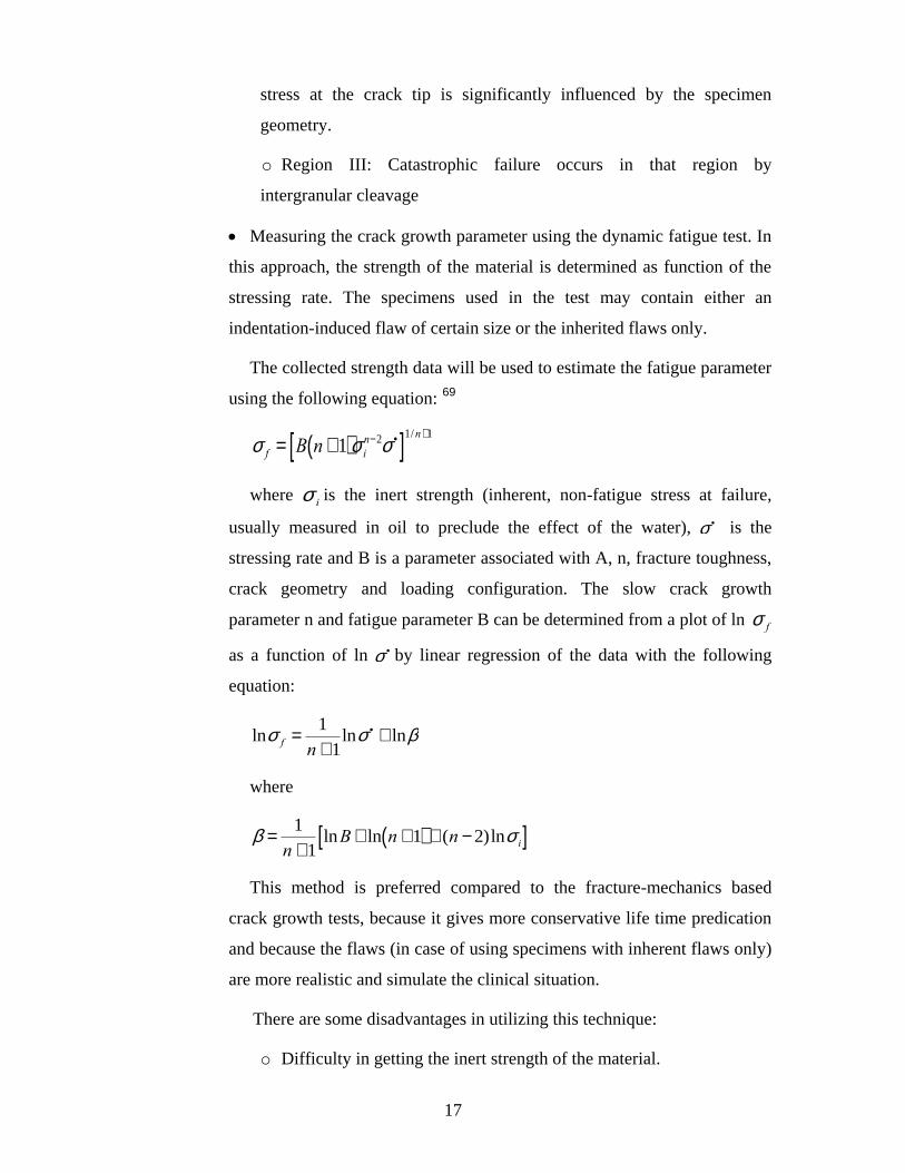
The collected strength data will be used to estimate the fatigue parameter
using the following equation: 69
s f = B n +1( )s i
n-2s ·[ ]1/n+1
where
s iis the inert strength (inherent, non-fatigue stress at failure,
usually measured in oil to preclude the effect of the water),
s · is the
stressing rate and B is a parameter associated with A, n, fracture toughness,
crack geometry and loading configuration. The slow crack growth
parameter n and fatigue parameter B can be determined from a plot of ln
s f
as a function of ln
s · by linear regression of the data with the following
equation:
lns f =1
n +1lns · + lnb
where
b =1
n +1lnB+ ln n +1( ) + (n - 2)lns i[ ]
This method is preferred compared to the fracture-mechanics based
crack growth tests, because it gives more conservative life time predication
and because the flaws (in case of using specimens with inherent flaws only)
are more realistic and simulate the clinical situation.
There are some disadvantages in utilizing this technique:
o Difficulty in getting the inert strength of the material.
18
o Difficulty in choosing the range of the stressing rates due to
inconsistency in the response of different materials to stressing rate (i.e
some materials show a drop in the strength at high stressing rate).
o The fatigue parameters measured using this method do not
correspond with the parameters collected using the repetitive cyclic
loading.
3. Contact fatigue data: This technique is used to study the damage mode after
cyclic loading using a sharp or blunt indenter. The applicability of this technique
for studying the ceramic material has been limited previously due to the
difficulty encountered in monitoring and measuring the different damage modes
on relatively opaque dental ceramics, which required sectioning of different
samples at different stages during the test and examining them. Recently, a new
route was used, in which a transparent material with mechanical properties
matching those of the ceramic, cement and tooth structure were used to observe
the crack initiation and propagation without sectioning the samples.
1.5.5. Simulating the Clinical Situation in the Fatigue Testing
Some of the available mechanical cyclic fatigue tests have been reviewed and
revealed no consistent protocol. The test parameters (material, size and shape of the load
applicator, frequency, range of force, and number of cycles) have been varied in these
tests (Appendix I).
To simulate the clinical situation the following should be controlled:
1. Factors related to the loading environment: The test should be performed in
the water and preferably under thermocycling to resemble the oral environment.
22
2. Factors related to the sample:22
Samples should be fabricated to have realistic flaws that resemble the
clinical situation.
Reliable adhesive cements should be selected, with a narrow range of
elastic modulus.
19
It is difficult to standardize the dimensions and modulus properties of
natural teeth. Therefore, the use of an alternative with a modulus of
elasticity resembling dentin will help standardize the different variables
related to the crown’s supporting structure.
3. Factors related to the applied load:
Magnitude: A controversy can be seen in the literature regarding whether
the load should be selected according to the average biting force for an
average individual or according to the worst-case scenario by applying a
load comparable to the maximum biting force that was measured. Another
factor that could govern the force selection is the location of the tested
restoration because as stated previously, the biting forces increase from the
anterior to the posterior region.
The contact pressure applied should fall within the range of the measured
contact pressure clinically. The contact pressure depends on the contact area
between the load applicator and the sample and to lesser extent, on the
elastic modulus of the load applicator. 22
Force direction: It is preferable to subject the samples to both vertical
and lateral forces. The applicability of this suggestion is determined by the
loading machine capability to perform the cyclic loading in both directions.
Number of cycles: 10 6
and 10 8
cycles seems to be reasonable for testing
the dental ceramic materials. 53
Frequency of the cyclic loading: It is advisable to use a frequency
comparable to the frequency of the chewing cycle (1-2 Hz). This frequency,
if combined with a high number of cycles as suggested above, requires a
long period to perform the test and increases the cost of the test. 53
1.6. Survival Rates of All-Ceramic Crowns
Twenty-two clinical studies were included in a systematic review about clinical
complications in fixed prosthodontics.70
All-ceramic crowns showed the lowest
prevalence of complications (8%). However, most of these studies were of short-term
20
duration. In 18 of them, the study duration ranged between 1-4 years while 4 were for
more than 5 years. The most common complications encountered were crown fracture
(7%), loss of retention (2%), and need for endodontic treatment (1%). The incidence of
crown fracture increased with the length of the study. The relation between the fracture
incidence and location in the arch was discussed in ten articles. The molars showed
higher fracture rate (21%) compared to premolars (7%) and anterior teeth (3%).
Kelly 4 reviewed ten articles about the survival rates of all-ceramic crowns. He found
that four materials (IPS Empress, In-Ceram Alumina and Spinell, and Procera Allceram)
have been extensively studied. He stated that the lowest failure rates were for In-Ceram
Alumina and Procera Allceram. The fracture rates seemed to be higher in the posterior
crowns compared to the anterior.
Studies that have reported the survival and fracture rates of all-ceramic crowns are
summarized in Appendix II.
1.7. Zirconium Oxide Ceramics
Zirconium oxide occurs in three crystalline forms: monoclinic, tetragonal and cubic.
Pure zirconium oxide occurs as monoclinic crystals at room temperature and transforms
into tetragonal at 1170ºC and then to cubic crystal at 2370ºC. During cooling, the crystals
will transform to monoclinic crystals at about 970 ºC. This transformation is
accompanied by a decrease in the flexure strength and volume expansion (3-4%).71
Zirconium oxide cubic or tetragonal crystals can be partially stabilized at room
temperature by adding a stabilizing oxide (e.g., CaO, MgO, CeO2 or Y203). Addition of
yttrium oxide to pure zirconia forms either PSZ (Partially Stabilized Zirconia) or Y-TZP
(Yttrium Tetragonal Zirconia Polycrystals). At room temperature, PSZ consists mainly of
cubic crystals with traces of monoclinic and tetragonal crystals, while Y-TZP consist of
tetragonal crystals. The amount of tetragonal crystals depends on grain size, yttrium
oxide content and the degree of constraints exerted on them by the matrix.71
Tetragonal
crystals in Y-TZP are metastable and can be transformed to larger monoclinic crystals
with the application of any stress from cracks or flaws.58
This phenomenon is beneficial
in hindering crack growth and increasing the fracture toughness and is therefore called
“transformation toughening”.59
21
The aging of Y-TZP at 230 ºC for 400 hours in a water vapor environment caused a
reduction in the flexural strength.72
This reduction in strength was reversed with 1,000 ºC
reheating for 24 hours and attributed to micro-crack formation at the surface as a result of
tetragonal-monoclinic crystal transformation. Ishgi et al. 73
reported an increase in the
flexural strength of polished or sandblasted zirconium oxide ceramic after sintering
compared to control sintered zirconium oxide specimens. Also, they reported a reduction
in the flexural strength of the ground samples after “veneer simulated firing”. This
reduction in the flexural strength after heat treatment could be explained by relaxation of
the residual compressive stresses that developed on the surface of the specimens due to
surface treatment.74
Papanagiotou et al.75
found no significant degradation of the flexural
strength of zirconium oxide samples subjected to polishing and low-temperature
degradation (24 hours or 7 days in boiling water or in humidifier at 250 ºC), while
samples treated with airborne-particle abrasion showed an increase in the flexural
strength. However, low-temperature degradation resulted in loss of yttrium, which could
decrease tetragonal-phase stability and long-term performance of zirconium.
In dentistry, Y-TZP is used to fabricate a substructure for crowns and FPDs. Y-TZP
sintering is accompanied by high volume shrinkage (20 – 25 %).58, 76
Therefore, the
current technology does not allow us to fabricate crowns and FPDs frameworks by direct
sintering on dies. There are two approaches to compensate for this sintering shrinkage in
order to develop prosthetic frameworks using partially-sintered zirconium oxide ceramics.
The first approach is to fabricate an oversized framework which will shrink to the proper
size after sintering. In this approach partially-sintered bar coded blocks are used to mill
the substructure. These bar codes are indicators of each block’s density and are used to
calculate the size needed to compensate for the actual sintering shrinkage. The other
approach is to fabricate the framework on an oversized die. After sintering, this oversized
framework will shrink to the proper size. Both approaches need precise measurement of
the sintering shrinkage utilizing the CAD/CAM technology. Another approach is to grind
the crowns using fully sintered zirconium oxide.77
Because it is fully sintered, the
infrastructures are milled to the exact size. The milling process of fully sintered Y-TZP is
slower, increases the wear of the cutting hardware and can introduce some microcracks
in the core material.58, 78
22
Several Y-TZP systems are available for the fabrication of the infrastructure for
crowns and FPDs. The majority of these infrastructures are fabricated from partially
sintered Y-TZP blanks (e.g., In-Ceram YZ, Vita Zahnfabrik, Bad Sackingen, Germany;
Cercon, Dentsply Ceramco, York, PA; Lava, 3M Espe, St. Paul, MN, Procera AllZirkon,
Noble Biocare, Yorba Linda, CA). Fully sintered Y-TZP can be used to fabricate the
infrastructures in some of the systems (e.g., DC-Zirkon, Smartfit, Austenal, Chicago,
IL).76
One of the disadvantages of Y-TZP is that it is not transparent and can not be stained
to give good esthetic results. Therefore, Y-TZP must be veneered with suitable veneering
porcelain to enhance esthetics.36
The application of the veneering porcelain on top of the ceramic coping could
introduce multiple flaws and interfaces, and complicate the nature of stresses within the
restoration. In a previous study, we reported that the fracture of the crowns made with
zirconium oxide substructure was a combination of chipping within the veneering
porcelain and delamination at the core-veneer interface.79
Interfacial failure was the
basic cause of failure for Y-TZP crowns in other in-vitro studies.80-82
Data collected from
failed clinical crowns showed a similar type of failure for multilayer crowns.83
In general, the fracture of multilayer crowns starts at their weakest part. In cases
where a stronger and stiffer core substructure is veneered with weaker porcelain, the
failure typically occurs in the weak veneering porcelain or at the weak bond between the
core and veneer.84
Several factors can affect the flexural strength of all-ceramic
veneering materials. The effect of these factors has been discussed previously. A weak
core-veneer bond can result from:
1. Structural flaws at the interface that might develop during veneering
porcelain application due to poor wettability.85, 86
2. Tetragonal monoclinic transformation which causes microscopic uplifts on
the surface due to the formation of larger monoclinic crystals.87, 88
This
transformation can be initiated during the multiple firing of veneering porcelain
on the zirconium oxide core.74
3. Firing shrinkage of the veneering porcelain.84
23
4. Interfacial tensile stresses at the core-veneer interface as a result of mismatch
in CTE.85
5. Low interfacial toughness compared to fracture toughness of core material:
The ratio of interfacial toughness to the core’s toughness, as well as the elastic
modulus ratio of the two materials, are determinant factors for the propagation
of cracks along or through the interface.89, 90
Several studies reported the core-veneer bond strengths for different zirconium oxide
systems (Appendix III). The following points were noticed from these studies:
Different methodologies were used in these studies, which hinder the
comparison between the results.
Zirconia/veneer bond strength was compared to metal/veneer bond strength
in 6 studies.91-96
Two studies reported no significant difference between bond of
veneering porcelain to zirconia or metal91, 92
and 3 studies reported higher bond
strength to metal in comparison to zirconia.93-95
On the other hand, only one
study reported a higher bond strength to zirconia in comparison to metal.96
All of the studied systems showed cohesive fractures of the veneers,
interfacial core-veneer fractures or a combination of both. None of the samples
failed cohesively through the zirconia core.
The effect of the veneering porcelain composition on the bond strength did
not receive adequate attention in the literature. One study reported that the
presence of zirconium in the veneering porcelain composition improved the
bond strength to zirconia.97
Another study reported higher zirconia/porcelain
bond strength for leucite containing pressable veneering porcelains compared to
non-leucite containing pressable veneering porcelains. 98
The use of liners affected the bond strength and the fracture mode of the
tested specimens. The effect of liner on the bond strength was material
dependent. 84, 99, 100
The effect of different surface treatments was reported in some of these
studies. The results of these studies were heterogeneous and were material-
dependent for some of them.97, 99-104
The effect of different surface treatment on
24
the crystal transformation was investigated. The highest amount of the
monoclinic phase was found after sandblasting. However, these phase changes
did not influence the core-veneer bonding. 101
Five studies evaluated the bond strength of pressed veneering porcelain to
zirconia. 95,
105-107,
108
Three of these studies reported no significant difference
between the layered and pressed sample,105-107
while the results of two other
studies reported higher bond strength for the pressed samples in comparison to
the layered ones.95, 108
In addition, the use of pressable porcelain on zirconium
oxide cores shifted the failure mode to be primarily cohesive failure in the
veneering layer compared to layered veneering porcelains which showed high
percentage of interfacial failures. This improvement in the bonding strength
could be explained by the improvement in the contact between the core and
veneering porcelain materials due to applied pressure during pressing, by
decreasing the chance of microgap formation as result of deformation and
cooling stresses, and by the reduction of the residual stresses and the tetragonal
to monoclinic crystal transformation at the interface due to the elimination of the
multiple firing of the layered veneering porcelain.84
Currently, little is known about the mechanism of the bonding between
zirconia cores and the veneering porcelain. A recent study reported that zirconia
and alumina as core materials demonstrated adhesive bonding (mechanical) with
silicate porcelain veneers, whereas glass infiltrated alumina and lithium
disilicate glass ceramic have reactive bonding (chemical) towards silicate
veneers. 109
The chemical structure at the core-veneer interface was analyzed
using Energy Dispersive X-ray (EDX), which revealed that some of the veneer
elements diffused into the zirconium oxide layer to a depth of 8 -10 μm.84
It is well known that surface contamination of the zirconia core can affect its
bonding strength to the veneering porcelain. A recent study reported on
contamination of the surface of the zirconia crowns in dental laboratory. High
values of aluminum found on surface were probably caused by diffusion of
aluminum oxide from the base during sintering. This difference between
declared composition and composition found in this investigation could affect
the bonding of zirconia and layered ceramic. 110

25
During the last 3 years, many manufacturers developed colored zirconia
cores. The effect of using these colored cores on the bond strength has been
investigated. The bond strength to colored zirconia was significantly weaker
compared to white zirconia frameworks. Although no marked chemical
differences between the examined zirconia materials could be found, there were
microstructural differences, especially between white and colored zirconia and
for different zirconia frameworks from different manufacturers, which
significantly affected core–veneer bond strength values.99
The effect of mismatch in the coefficients of thermal expansion (CTE)
between the veneering porcelain and core material on the core-veneer bond
strength was investigated. Significant discrepancies in CTE between veneering
porcelains and zirconia significantly affect their bond strength and caused
spontaneous debonding during the porcelain firing. Fischer et al. 111
reported
that the mismatch in the CTE and the glass transition temperature significantly
affected the bond strength of veneering porcelain to zirconia and suggested that
a veneering ceramic for Y-TZP should have a value of ΔαΔT≈1000x10−6
(where
Δα=the difference between the CTE of the zirconia and the veneering porcelain
and ΔT=the difference between the glass transition temperature and the room
temperature) in order to provide highest bond strength of zirconia/veneering
ceramic composites.
The effect of cooling rate after veneering porcelain sintering on the
zirconia/veneer bond strength was evaluated in 2 studies. 112, 113
The first study
reported that the bond strength increased with rapid cooling in comparison to
slow cooling.113
The other study reported a material-dependent effect. The
zirconia/veneer bond strength of veneering porcelain that contains leucite
crystals in their composition was not affected by cooling rate, while samples
veneered with amorphous veneering porcelain fired according to a slow cooling
protocol showed a reduced bonding strength in comparison to samples fired
according to the fast cooling protocol. 112
The effect of multiple firing of the veneering porcelain on the bond strength
was examined by two studies. 103, 114
The results of both studies were
contradictory with one study reported an increase of the bond strength with the
26
increase in the number of firing cycles, 103
and the other study reporting a
decrease in the bond strength with the higher number of firing cycles.114
Different SEM examinations of failed zirconium oxide crowns in a previous in-vitro
study revealed multiple voids within the manually applied veneering porcelain, which
develop as a result of the human factor in building up these crowns79
. As stated
previously, these voids could compromise the ability of the all-ceramic restoration to
support the applied forces. Elimination of the human factor in application of the
veneering porcelain by the use of pressable ceramic on top of zirconium oxide
substructure is expected to improve the homogeneity within the veneering porcelain and
hence enhance its ability to withstand the applied forces.
A thorough literature search revealed nine clinical studies which reported the
survival and fracture rates of all-ceramic crowns made using zirconium oxide cores115-123
and one randomized clinical trial which compared the survival and fracture rate of full
coverage zirconium-oxide crowns to full coverage gold crowns124
(Appendix II). Only
two of these nine studies were randomized clinical trials that compared all-ceramic
zirconium-oxide crowns to crowns made using glass-infiltrated zirconia-reinforced
alumina core115
or metal-ceramic crowns118
. The rest of the studies were case series. The
number of zirconia-based restorations ranged between 15 and 248 crowns and eight
different zirconium-oxide systems were used in these studies. The follow-up periods
ranged between 1 and 5 years. All the studies, except two, reported at least an incidence
of veneering porcelain fracture during the follow-up period. Most of these studies did not
report any details about the coping design and the firing protocol of the veneering
porcelain.
27
Chapter 2: Rationale and Objectives
28
Rationale and Objectives
The previous literature review makes it clear that the veneering porcelain or the
core-veneer interface represents the weakest part of all-ceramic crowns made using
zirconium oxide cores. The aim of this project was to study different factors affecting the
fatigue resistance and fracture strength of all-ceramic molar crowns made using
zirconium oxide cores.
The objectives of this thesis were:
To evaluate the effect of varying the total thickness, core thickness, and
veneering porcelain application techniques (pressing vs. manual build-up) on the
fracture strength and mode of bilayered zirconia-porcelain samples. (Chapter 3)
To evaluate the influence of varying the core thickness and modifying the
core design on the fracture strength and mode of zirconia-based crowns and to
compare these results to those of metal-ceramic crowns. (Chapter 4)
To evaluate the influence of using different veneering techniques and core
designs on the fracture strength and mode of zirconia-based crowns made using
CAD-CAM-produced veneering layers. (Chapter 5)
To study the nature of the bond between the zirconium oxide core and
matching veneering porcelain materials. (Chapter 6)
29
Chapter 3: Manuscript 1
30
Effect of total thickness, core thickness and veneering porcelain application
technique on fracture of zirconia/porcelain combinations
Mohammed H. Zahran, BDS, MSc, PhD-candidate
Department of Prosthodontics, Faculty of Dentistry, University of Toronto, Toronto, ON, Canada
Department of Fixed Prosthodontics, Faculty of Dentistry, King Abdulaziz University, Jeddah,
Saudi Arabia
*Omar El-Mowafy, BDS, PhD, FADM
Professor and Head, Department of Restorative Dentistry, Faculty of Dentistry, University of
Toronto, Toronto, ON, Canada
Asbjorn Jokstad, DDS, PhD
Professor and Head, Department of Prosthodontics, Faculty of Dentistry, University of Toronto,
Toronto, ON, Canada
University of Tromso, Norway
Amin S. Rizkalla, P Eng, PhD
Associate Professor,, Dentistry, Schulich School of Medicine & Dentistry, Western University,
London, ON, Canada
Laura E. Tam, DDS, MSc
Professor, Department of Restorative Dentistry, Faculty of Dentistry, University of Toronto,
Toronto, ON, Canada
*Corresponding author
Omar El-Mowafy, BDS, PhD, FADM
Department of Clinical Sciences
Faculty of Dentistry, University of Toronto
124 Edward Street, Toronto, Ontario M5G 1G6, Canada.
Phone: (416) 979-4934 X 4572
Fax: (416) 979-4936
E-mail: [email protected]
Short Title: Fracture of zirconia/porcelain combinations
This work was previously presented in part at the 89th General Session & Exhibition of the
IADR, San Diego, CA, USA in 2011
31
Abstract
Objective: to determine the effect of varying total thickness, core thickness and veneering
porcelain application technique on the fracture strength of bilayered porcelain-zirconia discs.
Methods: Zirconia square specimens (8 x 8 mm) were prepared in three thicknesses (0.6, 0.8 and
1.0 mm). The zirconia specimens were veneered with pressed (P) or manually-applied (M)
veneering porcelain to produce specimens with 1.5 or 2 mm total thickness. The discs were
cemented to epoxy resin blocks and loaded to failure at the center of the veneering porcelain.
Fracture load and mode were recorded and analyzed using factorial ANOVA and Chi-square test,
respectively. Results: Factorial ANOVA revealed a statistically-significant main effect on mean
fracture loads (P<0.05) for the following variables: total thickness [Mean(SD): 1.5
mm=1,178(273) N and 2 mm=1,464 (331) N], core thickness [(Mean(SD): 0.6 mm=1,196(381)
N, 0.8 mm=1,332(296) N and 1mm=1,436 (280) N] and veneering material application method
[(Mean(SD): P=1,405(310) N and M=1,237 (339) N]. Higher fracture loads were associated with
the greater total thickness, the greater core thickness and the pressed application technique
groups. Chi-square revealed a significant effect on mode of fracture for the total thickness and
core thickness (P<0.05), but not for the veneer application method. An increase in the percentage
of the specimens with both core and veneer fracture was observed for the lesser total thickness
group and the greater core thickness group. Significance: The lowest fracture strengths and
greatest incidence of both core and veneer porcelain fracture mode were associated with the 1.5
mm total porcelain thickness groups. A 2 mm thickness of porcelain is preferable in occlusal
stress areas. Pressed veneering porcelain improved the fracture strength of the bilayered zirconia-
porcelain samples in comparison to the manually-applied ones.
Keywords: Fracture load; fracture mode: zirconium oxide ceramics; veneering porcelain;
thickness; thickness ratio
32
Introduction
The increasing demand for esthetics in combination with health and environmental
concerns of metallic restorations stimulated dental manufacturers and dentists to explore
alternatives such as all-porcelain restorations. However, the clinical performance of all-
ceramic restorations has been short of ideal due, to a great extent, to their inherent
brittleness, which makes them more susceptible to fracture, especially in the posterior
region of the mouth.1,2
In the past decade, dental manufacturers focused their efforts on developing new all-
porcelain products with enhanced mechanical properties to improve their clinical
performance in the posterior region through better resistance to chipping and fracture.
Yttrium-tetragonal zirconia poly-crystals (Y-TZP) is one of these products that received
special attention due to its high flexural strength and fracture toughness.3 The tetragonal
crystals in these zirconium oxide ceramics are meta-stable and can be transformed into
larger monoclinic crystals with the application of stress from cracks or flaws.4 This
phenomenon is beneficial in hindering crack growth and increasing fracture toughness;
hence, it is referred to as “transformation toughening”.5 However, Y-TZP-based
products cannot provide optimal esthetics because they have high opacity and are
difficult to stain. Therefore, Y-TZP is frequently used as a core material and coated with
veneering porcelain to enhance esthetics.6
The improved mechanical properties of zirconia-based restorations were not readily
reflected in their clinical performance with several short-term clinical studies reporting a
high incidence of veneering porcelain chipping.7-13
This high chipping rate, in
comparison to that of metal-ceramic restorations, led manufacturers and clinicians to
seek explanations and search for solutions. Several hypothetical explanations have been
reported, including: occlusal overloading, residual stresses as a result of the mismatch in
the coefficient of thermal expansion (CTE) between core and veneering porcelain, 14, 15
residual “tempering” stresses due to the thermal gradient between the veneering
porcelain and the zirconia core,15
interfacial stresses as a result of crystal transformation
at the interface,16
inadequate framework support,17
inherent strength deficiency of the
veneering porcelain 17, 18
and a weak porcelain-zirconia bond.19, 20
Several potential
solutions were suggested in clinical and in-vitro studies to improve the clinical
performance of zirconia-based restorations. These were mainly directed towards
33
improving the strength of the veneering layer and the veneer-to-core bond. The use of the
pressing method to apply the veneering porcelain was suggested as an alternative to the
manual build-up method to decrease the number and size of the internal flaws within the
veneering layer, thus eliminating the potential for micro-crack formation and
propagation.21
Other suggestions were directed towards enhancing the core design to
provide adequate and even support to the veneering porcelain,22, 23
developing stronger
veneering materials9 and modifying the core to veneer thickness ratio to enhance the
overall strength of the crown.24
The aim of this study was to evaluate the effect of varying overall thickness, zirconia
core thickness and veneering porcelain application techniques on the fracture strength of
bilayered zirconia-porcelain discs. Revealing the effects of these factors will improve our
understanding of the strength and limitations of porcelain crowns made with zirconium
oxide cores and will help us in improving the design of the crowns in order to optimize
their strength. The objectives were to test the following null hypotheses: There is no
significant difference in the fracture strength and fracture mode of zirconia-porcelain
specimens fabricated using two different total porcelain thicknesses (1.5 and 2.0 mm),
three different zirconia core thicknesses (0.6, 0.8 and 1.0 mm) and two different
veneering porcelain application techniques (pressed and manual).
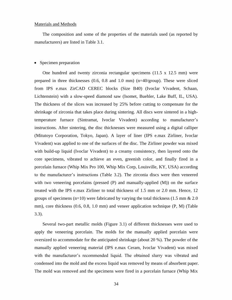
34
Materials and Methods
The composition and some of the properties of the materials used (as reported by
manufacturers) are listed in Table 3.1.
Specimen preparation
One hundred and twenty zirconia rectangular specimens (11.5 x 12.5 mm) were
prepared in three thicknesses (0.6, 0.8 and 1.0 mm) (n=40/group). These were sliced
from IPS e.max ZirCAD CEREC blocks (Size B40) (Ivoclar Vivadent, Schaan,
Lichtenstein) with a slow-speed diamond saw (Isomet, Buehler, Lake Buff, IL, USA).
The thickness of the slices was increased by 25% before cutting to compensate for the
shrinkage of zirconia that takes place during sintering. All discs were sintered in a high-
temperature furnace (Sintramat, Ivoclar Vivadent) according to manufacturer’s
instructions. After sintering, the disc thicknesses were measured using a digital calliper
(Mitutoyo Corporation, Tokyo, Japan). A layer of liner (IPS e.max Zirliner, Ivoclar
Vivadent) was applied to one of the surfaces of the disc. The Zirliner powder was mixed
with build-up liquid (Ivoclar Vivadent) to a creamy consistency, then layered onto the
core specimens, vibrated to achieve an even, greenish color, and finally fired in a
porcelain furnace (Whip Mix Pro 100, Whip Mix Corp, Louisville, KY, USA) according
to the manufacturer’s instructions (Table 3.2). The zirconia discs were then veneered
with two veneering porcelains (pressed (P) and manually-applied (M)) on the surface
treated with the IPS e.max Zirliner to total thickness of 1.5 mm or 2.0 mm. Hence, 12
groups of specimens (n=10) were fabricated by varying the total thickness (1.5 mm & 2.0
mm), core thickness (0.6, 0.8, 1.0 mm) and veneer application technique (P, M) (Table
3.3).
Several two-part metallic molds (Figure 3.1) of different thicknesses were used to
apply the veneering porcelain. The molds for the manually applied porcelain were
oversized to accommodate for the anticipated shrinkage (about 20 %). The powder of the
manually applied veneering material (IPS e.max Ceram, Ivoclar Vivadent) was mixed
with the manufacturer’s recommended liquid. The obtained slurry was vibrated and
condensed into the mold and the excess liquid was removed by means of absorbent paper.
The mold was removed and the specimens were fired in a porcelain furnace (Whip Mix
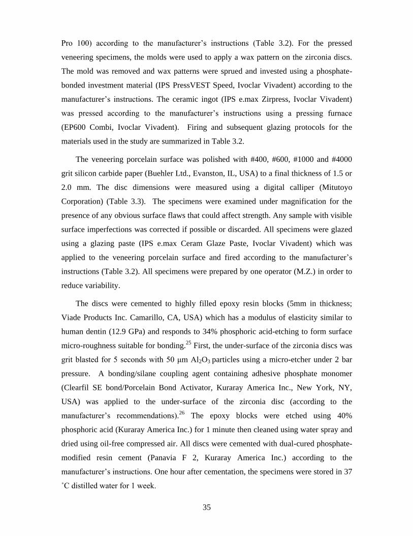
35
Pro 100) according to the manufacturer’s instructions (Table 3.2). For the pressed
veneering specimens, the molds were used to apply a wax pattern on the zirconia discs.
The mold was removed and wax patterns were sprued and invested using a phosphate-
bonded investment material (IPS PressVEST Speed, Ivoclar Vivadent) according to the
manufacturer’s instructions. The ceramic ingot (IPS e.max Zirpress, Ivoclar Vivadent)
was pressed according to the manufacturer’s instructions using a pressing furnace
(EP600 Combi, Ivoclar Vivadent). Firing and subsequent glazing protocols for the
materials used in the study are summarized in Table 3.2.
The veneering porcelain surface was polished with #400, #600, #1000 and #4000
grit silicon carbide paper (Buehler Ltd., Evanston, IL, USA) to a final thickness of 1.5 or
2.0 mm. The disc dimensions were measured using a digital calliper (Mitutoyo
Corporation) (Table 3.3). The specimens were examined under magnification for the
presence of any obvious surface flaws that could affect strength. Any sample with visible
surface imperfections was corrected if possible or discarded. All specimens were glazed
using a glazing paste (IPS e.max Ceram Glaze Paste, Ivoclar Vivadent) which was
applied to the veneering porcelain surface and fired according to the manufacturer’s
instructions (Table 3.2). All specimens were prepared by one operator (M.Z.) in order to
reduce variability.
The discs were cemented to highly filled epoxy resin blocks (5mm in thickness;
Viade Products Inc. Camarillo, CA, USA) which has a modulus of elasticity similar to
human dentin (12.9 GPa) and responds to 34% phosphoric acid-etching to form surface
micro-roughness suitable for bonding.25
First, the under-surface of the zirconia discs was
grit blasted for 5 seconds with 50 μm Al2O3 particles using a micro-etcher under 2 bar
pressure. A bonding/silane coupling agent containing adhesive phosphate monomer
(Clearfil SE bond/Porcelain Bond Activator, Kuraray America Inc., New York, NY,
USA) was applied to the under-surface of the zirconia disc (according to the
manufacturer’s recommendations).26
The epoxy blocks were etched using 40%
phosphoric acid (Kuraray America Inc.) for 1 minute then cleaned using water spray and
dried using oil-free compressed air. All discs were cemented with dual-cured phosphate-
modified resin cement (Panavia F 2, Kuraray America Inc.) according to the
manufacturer’s instructions. One hour after cementation, the specimens were stored in 37
˚C distilled water for 1 week.
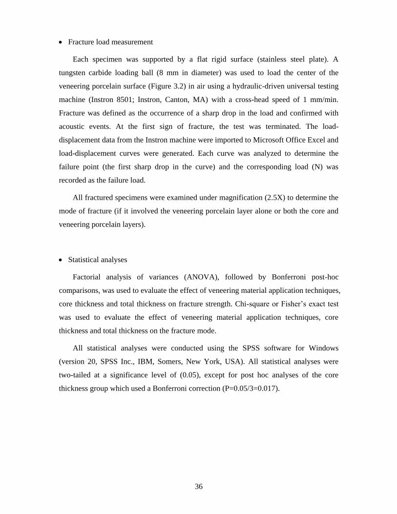
36
Fracture load measurement
Each specimen was supported by a flat rigid surface (stainless steel plate). A
tungsten carbide loading ball (8 mm in diameter) was used to load the center of the
veneering porcelain surface (Figure 3.2) in air using a hydraulic-driven universal testing
machine (Instron 8501; Instron, Canton, MA) with a cross-head speed of 1 mm/min.
Fracture was defined as the occurrence of a sharp drop in the load and confirmed with
acoustic events. At the first sign of fracture, the test was terminated. The load-
displacement data from the Instron machine were imported to Microsoft Office Excel and
load-displacement curves were generated. Each curve was analyzed to determine the
failure point (the first sharp drop in the curve) and the corresponding load (N) was
recorded as the failure load.
All fractured specimens were examined under magnification (2.5X) to determine the
mode of fracture (if it involved the veneering porcelain layer alone or both the core and
veneering porcelain layers).
Statistical analyses
Factorial analysis of variances (ANOVA), followed by Bonferroni post-hoc
comparisons, was used to evaluate the effect of veneering material application techniques,
core thickness and total thickness on fracture strength. Chi-square or Fisher’s exact test
was used to evaluate the effect of veneering material application techniques, core
thickness and total thickness on the fracture mode.
All statistical analyses were conducted using the SPSS software for Windows
(version 20, SPSS Inc., IBM, Somers, New York, USA). All statistical analyses were
two-tailed at a significance level of (0.05), except for post hoc analyses of the core
thickness group which used a Bonferroni correction (P=0.05/3=0.017).
37
Results
Fracture load
The loads at fracture of all groups are reported in Table 3.4. Factorial ANOVA
revealed significant main effects of the veneering porcelain application method, core
thickness and total thickness on the fracture load (P ≤0.001) but not for the interaction
terms (Table 3.5). Table 3.6 shows the effect of the independent variables on load at
fracture.
Fracture mode
Distributions of the different fracture modes among the test groups are shown in
Table 3.7. Approximately 58% of the total number of specimens showed a pattern of
fracture that involved the veneering porcelain layer only. Chi-square test revealed
significant effects on the fracture mode of both the core thickness and the total thickness
(P ≤0.001 and P =0.002, respectively), but not the veneering porcelain application
method (Table 3.8). Decreasing the specimen thickness from 2 to 1.5 mm or increasing
the core thickness from 0.6 mm to 1 mm increased the percentage of both core and
veneer fracture.
Representative images of the fractured specimens can be seen in Figure 3.3.
38
Discussion
Most manufacturers are reporting the flexural strength of zirconium oxide cores and
veneering porcelain separately, despite the fact that cores and veneering porcelains are
not separate in the real clinical situation. In this study, composite specimens of zirconia
cores and veneering porcelains were tested in a manner more representative of the
clinical situation. A simple geometrical form of specimens was followed instead of an
actual crown in order to simplify analysis of the variables and to avoid the complexity of
stresses that develop in anatomical crowns. The recommendations for a clinically-
relevant in-vitro load-to-failure test for all-ceramic restorations described by Kelly were
followed in this study,27
including specimen preparation according to the clinical
standards and with clinically-relevant dimensions, and the use of a die material with
elastic modulus similar to that of dentin to avoid variability associated with natural teeth.
The total thicknesses were selected to reflect the recommended reduction at the
functional and non-functional cusps in molars (2 and 1.5 mm, respectively).
In this study, specimens with pressed veneering porcelain had significantly higher
fracture load than the ones with manually-applied porcelain. A similar finding was
previously reported.28
Although both veneering porcelains have a similar fluorapatite
glass-ceramic composition, the flexure strength of the pressed veneering porcelain is
higher than the manually-applied porcelain according to manufacturers’ reports (Table
3.1). The manually-applied technique has the risk of void formation. A void within the
veneering porcelain could act as a flaw for initiation of fracture within the veneering
porcelain and contribute to lower fracture strength results. Because porcelain fracture
resistance is improved by bonding to an underlying more resilient substrate, a more
intimate contact between the zirconia core and veneering porcelain and fewer interfacial
voids in the pressed technique29
, due to the applied pressure under vacuum, likely
enhanced the ability of the pressed veneering porcelain to withstand the applied forces.
The higher fracture loads for specimens with 2 mm total thickness in comparison to
1.5 mm total thickness might be related to the increase in volume of the specimen. It has
to be emphasized that the increase in the total thickness (d) for samples with similar core
thickness resulted from increasing the thickness of veneering layer (dv), which increases
the critical load for radial crack in the core and cone crack in the veneer layer. This
increase is higher for the radial cracking relative to the cone cracking, which renders the
39
specimen more susceptible to cone cracking of the veneering layer 30
and might explain
the increase in the fracture loads and the tendency towards more fractures involving the
veneering layer only by the 2 mm total thickness group.
Significant effects of the core thickness on the fracture strength and fracture mode
were found in this study. Higher fracture loads and lower percentages of fractures
involving the veneer layer only were observed with increasing the core thickness.
Although there was no significant interaction effect, it appears that the fracture strength
of the 1.5mm total thickness specimens was more affected by a reduced core thickness
(and hence, a reduced core to veneer thickness ratio) than the 2mm total thickness
specimen (Figure 3.4). Other studies have reported an increase in strength with the
increase in the core to veneer thickness ratio.6, 31, 32
White et al. used (4x4x40 mm) beams,
representing fixed dental prosthesis but not dental crowns, and reported that increasing
the core to veneer thickness ratio increased the modulus of rupture of beams that were
composed of zirconia core and matching veneering porcelain materials using 3-point
bending test.6 Fleming et al. used a biaxial flexural test to assess the effect of varying the
aluminous core: porcelain thickness ratio and found similar results.31
An increase in the
number of fracture fragments, Hertzian cone and delamination were associated with a
decrease in core to veneer thickness ratio. Wakabayashi and Anusavice32
used bilayered
alumina-porcelain discs supported with different substrates on a design similar to the one
used in this study. They reported that increasing the core to veneer thickness ratio
increased the flexure strength and shifted the crack initiation site from veneer to core.
However, the core to veneer thickness ratios varied in two of the above studies within a
fixed overall thickness 6, 32
, while in the third study,31
the ratio was varied by changing
the core, veneer and overall thickness. It must be emphasized that comparing the results
of the present study with those of the above studies might be difficult due to variability in
materials, thicknesses, specimen designs and test methods.
There appeared to be an increasing incidence of both core and veneer fractures in the
1.5 mm total thickness specimens when the core thickness increased from 0.6 to 1mm,
and the incidence of those fractures was near 100% when the core thickness was 1 mm.
The change in the fracture mode with the increase in the core thickness for specimens
with 1.5 mm overall thickness can be explained by the shielding effect of the
compressive stresses under the loading ball within the thin veneering layer which acts to
40
protect the veneer from developing cone cracks, resulting in increasing the combined
failures of both veneer and core. This shielding effect faded in specimens with increased
veneer thickness, with subsequent increase in the percentages of failures involving the
veneering porcelain only. In contrast, varying the core thickness did not appear to affect
the fracture mode among specimens with 2 mm total thickness. This supports fracture
load and mode insensitivity to variation in the core to veneer thickness ratio among the
specimens with veneering porcelain thickness > 1 mm and reflects the importance of the
veneering porcelain thickness as an influential factor on the fracture load and mode of the
zirconia-porcelain specimens (Figure 3.4 and Table 3.7). It is clear that the impact of the
fracture within the veneering layer only might not be as serious as the bulk fracture. The
latter will require the replacement of the restoration, while the earlier might be addressed
by re-contouring or chairside repair.
The high chipping rate of the veneering porcelain on zirconia framework triggered
the researchers to study the stress profile in an attempt to correlate the stresses within the
veneering layer with the chipping behavior. Residual stresses within the veneering layer
can be generated as a result of thermal gradients occurring during the cooling of the
veneer during fabrication and the mismatch in thermal expansion properties between the
core and veneering porcelain.33
The thermal gradient within the bilayered system is
determined by the thermal properties of both layers, thickness and cooling rate. Mainjot
et al. in a series of studies evaluated the effect of cooling rate and framework and veneer
thickness on the stress profile within the veneering porcelain using the hole-drilling
method.33-36
In one study, zirconia discs (thickness from 0.5 to 3 mm) were veneered
with 1.5 mm veneering porcelain. Specimens with 1.5 mm zirconia had the most
favorable stress profile with internal compressive stresses near the veneer-core interface,
while all other framework thicknesses exhibited either surface or internal tensile
stresses.35
In another study,36
1 mm thick zirconia discs were veneered using different
thicknesses ranging from 1 to 3 mm. All specimens, except the ones with 1.5 mm veneer,
exhibited compressive stresses at the surface of the veneer that changed to tensile nature
at the 0.5 -1 mm depth and then reverted to compressive near the framework. In contrast,
specimens with 1.5 mm veneer exhibited only interior tensile stresses. These studies
varied the core to veneer thickness ratio by varying the thicknesses of the core or the
veneer without fixing the total thickness, which makes it difficult to separate the effect of
41
the ratio from that of the total thickness and to correlate the results of these studies with
the findings of the present study. Perhaps future work should be directed towards
correlating the residual stresses within the veneering porcelain of zirconia-porcelain
bilayered specimens with fracture strength and mode.
Since all loading in this study was uniaxial and other forces were ignored due to the
machine limitations, the clinical implication of the results of the present study should be
interpreted with caution. Fracture loads were recorded when there was a sharp drop in the
load-displacement curve accompanied by acoustic sound. However, the load at complete
fracture may not necessarily be the load that the material will withstand before crack
initiation. Generally, crack initiation occurs at a lower force compared to the one of
complete fracture. Once a crack is initiated, crack propagation starts leading to complete
fracture. This study did not record the “pop-in” crack (crack initiation) of the specimens
because the crack initiation was not accompanied by any drop in the load since the
loading ball was entirely supported by intact specimen surface. The use of tungsten
carbide loading ball increased the contact pressure in the specimen compared to the
clinical situation as the contact pressure is influenced by the ratio of the elastic modulus
of the porcelain to that of the loading ball, and by the radius of the loading ball.37
Alternative loading methods could have included the use of a ball with a modulus of
elasticity lower than that of tungsten carbide, a tin sheet between the load applicator and
crown as stress breaker or a stainless steel loading piston with its end machined to a
curvature equivalent to 40-50 mm diameter to reproduce clinically-relevant contact
pressure. However, this increase in the loading stresses will not eliminate the comparison
between the different test groups since all specimens were loaded using similar contact
pressure. Fracture load data reported in this study should be considered as relative, not
“absolute”, values and extrapolation of these in-vitro strength data to clinical
performance must be considered cautiously and within the limitations of the study.2
42
Conclusions
The current study highlighted the effects of the total thickness, core thickness and
veneering porcelain application method on the fracture strength and mode of the
bilayered zirconia/porcelain samples. Using pressed veneering porcelain increased the
fracture strength of the zirconia/porcelain samples compared to manually-applied
veneering porcelain, but had no effect on the fracture mode. The variable effect of the
core thickness among two total thicknesses (1.5 and 2 mm) underlined the importance of
the veneering thickness in influencing fracture strength and mode. Fracture load and
mode of specimens with veneering thickness less than 1 mm were affected by varying the
core thickness. This effect disappeared once the veneering porcelain thickness increased
beyond 1 mm.
43
Acknowledgements:
The current study is part of a PhD thesis submitted to the Faculty of Dentistry,
University of Toronto.
This work was supported by grants from the Faculty of Dentistry Research
Committee, University of Toronto; and Education and Research Foundation of
Prosthodontics. Materials donations were received from Ivoclar-Vivadent and Kuraray;
and technical support provided by Shaw Dental Labs (Toronto) to whom the authors are
grateful.
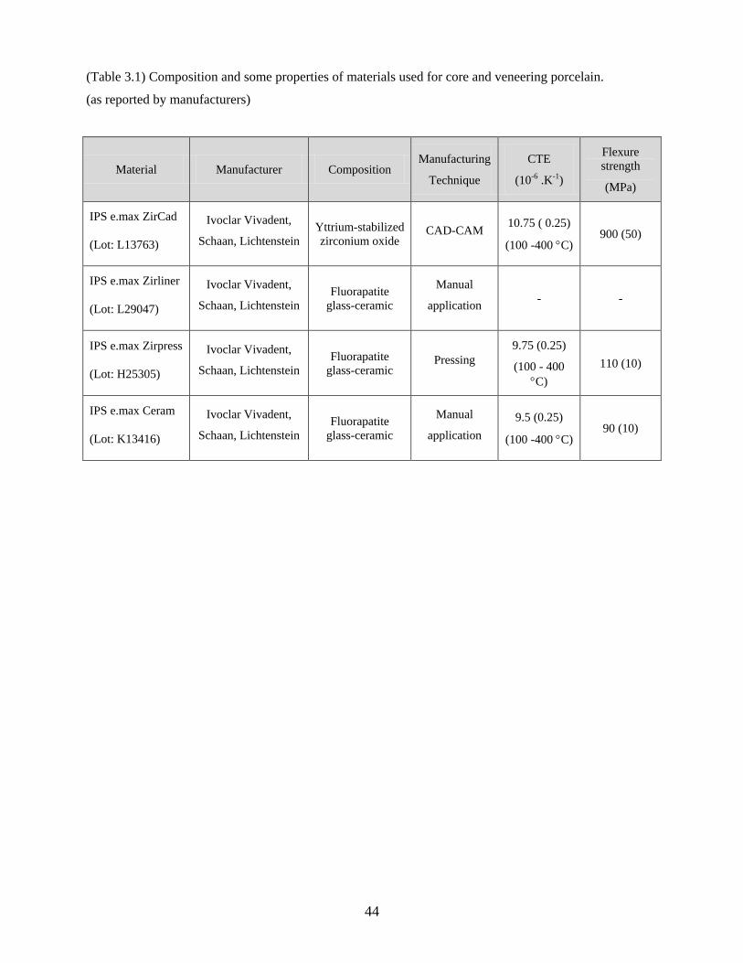
44
(Table 3.1) Composition and some properties of materials used for core and veneering porcelain.
(as reported by manufacturers)
Material Manufacturer Composition Manufacturing
Technique
CTE
(10-6 .K-1)
Flexure
strength
(MPa)
IPS e.max ZirCad
(Lot: L13763)
Ivoclar Vivadent,
Schaan, Lichtenstein
Yttrium-stabilized
zirconium oxide CAD-CAM
10.75 ( 0.25)
(100 -400 C) 900 (50)
IPS e.max Zirliner
(Lot: L29047)
Ivoclar Vivadent,
Schaan, Lichtenstein
Fluorapatite
glass-ceramic
Manual
application - -
IPS e.max Zirpress
(Lot: H25305)
Ivoclar Vivadent,
Schaan, Lichtenstein
Fluorapatite
glass-ceramic Pressing
9.75 (0.25)
(100 - 400
C)
110 (10)
IPS e.max Ceram
(Lot: K13416)
Ivoclar Vivadent,
Schaan, Lichtenstein
Fluorapatite
glass-ceramic
Manual
application
9.5 (0.25)
(100 -400 C) 90 (10)
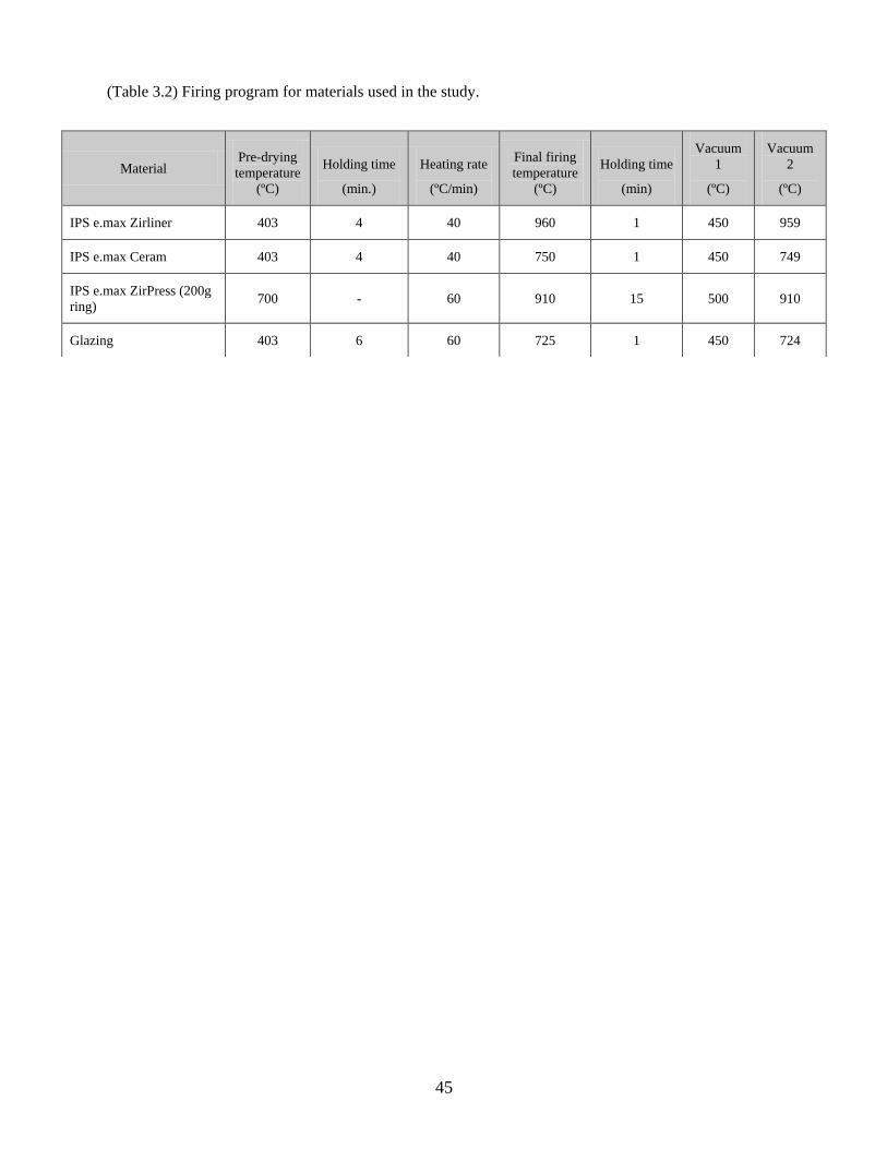
45
(Table 3.2) Firing program for materials used in the study.
Material Pre-drying
temperature
(ºC)
Holding time
(min.)
Heating rate
(ºC/min)
Final firing
temperature
(ºC)
Holding time
(min)
Vacuum
1
(ºC)
Vacuum
2
(ºC)
IPS e.max Zirliner 403 4 40 960 1 450 959
IPS e.max Ceram 403 4 40 750 1 450 749
IPS e.max ZirPress (200g
ring) 700 - 60 910 15 500 910
Glazing 403 6 60 725 1 450 724
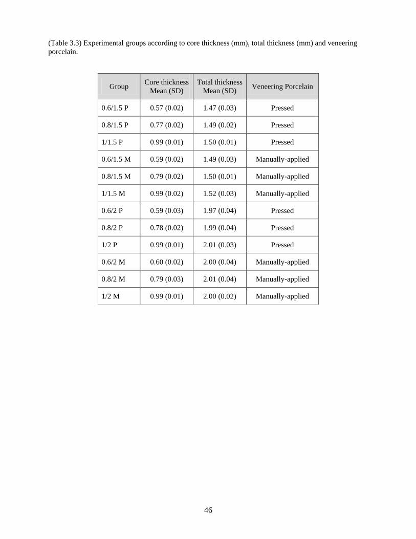
46
(Table 3.3) Experimental groups according to core thickness (mm), total thickness (mm) and veneering
porcelain.
Group
Core thickness
Mean (SD)
Total thickness
Mean (SD) Veneering Porcelain
0.6/1.5 P 0.57 (0.02) 1.47 (0.03) Pressed
0.8/1.5 P 0.77 (0.02) 1.49 (0.02) Pressed
1/1.5 P 0.99 (0.01) 1.50 (0.01) Pressed
0.6/1.5 M 0.59 (0.02) 1.49 (0.03) Manually-applied
0.8/1.5 M 0.79 (0.02) 1.50 (0.01) Manually-applied
1/1.5 M 0.99 (0.02) 1.52 (0.03) Manually-applied
0.6/2 P 0.59 (0.03) 1.97 (0.04) Pressed
0.8/2 P 0.78 (0.02) 1.99 (0.04) Pressed
1/2 P 0.99 (0.01) 2.01 (0.03) Pressed
0.6/2 M 0.60 (0.02) 2.00 (0.04) Manually-applied
0.8/2 M 0.79 (0.03) 2.01 (0.04) Manually-applied
1/2 M 0.99 (0.01) 2.00 (0.02) Manually-applied
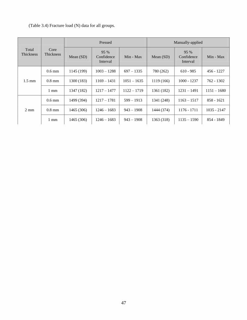
47
(Table 3.4) Fracture load (N) data for all groups.
Total
Thickness
Core
Thickness
Pressed Manually-applied
Mean (SD)
95 %
Confidence
Interval
Min - Max Mean (SD)
95 %
Confidence
Interval
Min - Max
1.5 mm
0.6 mm 1145 (199) 1003 – 1288 697 – 1335 780 (262) 610 - 985 456 - 1227
0.8 mm 1300 (183) 1169 – 1431 1051 – 1635 1119 (166) 1000 - 1237 762 - 1302
1 mm 1347 (182) 1217 – 1477 1122 – 1719 1361 (182) 1231 – 1491 1151 – 1680
2 mm
0.6 mm 1499 (394) 1217 – 1781 599 – 1913 1341 (248) 1163 – 1517 858 - 1621
0.8 mm 1465 (306) 1246 – 1683 943 – 1908 1444 (374) 1176 - 1711 1035 - 2147
1 mm 1465 (306) 1246 – 1683 943 – 1908 1363 (318) 1135 – 1590 854 - 1849
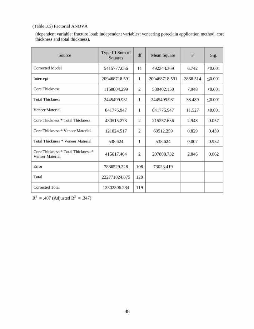
48
(Table 3.5) Factorial ANOVA
(dependent variable: fracture load; independent variables: veneering porcelain application method, core
thickness and total thickness).
R2 = .407 (Adjusted R2 = .347)
Source Type III Sum of
Squares df Mean Square F Sig.
Corrected Model 5415777.056 11 492343.369 6.742 ≤0.001
Intercept 209468718.591 1 209468718.591 2868.514 ≤0.001
Core Thickness 1160804.299 2 580402.150 7.948 ≤0.001
Total Thickness 2445499.931 1 2445499.931 33.489 ≤0.001
Veneer Material 841776.947 1 841776.947 11.527 ≤0.001
Core Thickness * Total Thickness 430515.273 2 215257.636 2.948 0.057
Core Thickness * Veneer Material 121024.517 2 60512.259 0.829 0.439
Total Thickness * Veneer Material 538.624 1 538.624 0.007 0.932
Core Thickness * Total Thickness *
Veneer Material 415617.464 2 207808.732 2.846 0.062
Error 7886529.228 108 73023.419
Total 222771024.875 120
Corrected Total 13302306.284 119
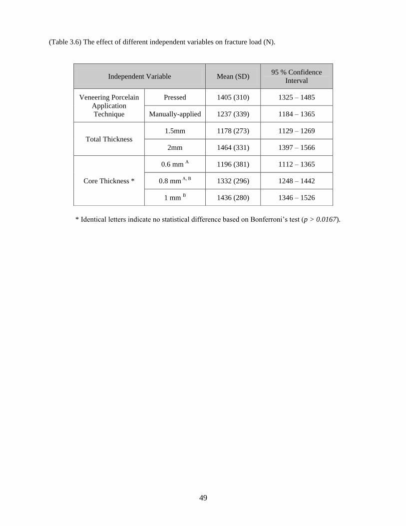
49
(Table 3.6) The effect of different independent variables on fracture load (N).
* Identical letters indicate no statistical difference based on Bonferroni’s test (p > 0.0167).
Independent Variable Mean (SD) 95 % Confidence
Interval
Veneering Porcelain
Application
Technique
Pressed 1405 (310) 1325 – 1485
Manually-applied 1237 (339) 1184 – 1365
Total Thickness
1.5mm 1178 (273) 1129 – 1269
2mm 1464 (331) 1397 – 1566
Core Thickness *
0.6 mm A 1196 (381) 1112 – 1365
0.8 mm A, B 1332 (296) 1248 – 1442
1 mm B 1436 (280) 1346 – 1526
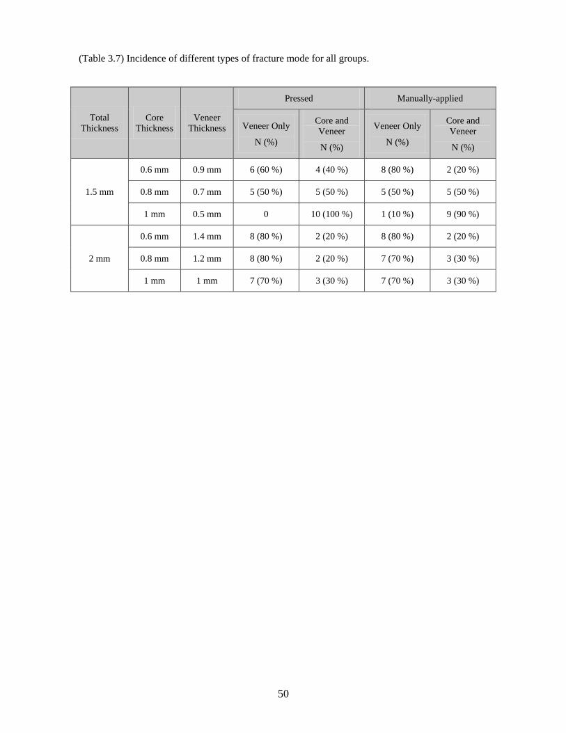
50
(Table 3.7) Incidence of different types of fracture mode for all groups.
Total
Thickness
Core
Thickness
Veneer
Thickness
Pressed Manually-applied
Veneer Only
N (%)
Core and
Veneer
N (%)
Veneer Only
N (%)
Core and
Veneer
N (%)
1.5 mm
0.6 mm 0.9 mm 6 (60 %) 4 (40 %) 8 (80 %) 2 (20 %)
0.8 mm 0.7 mm 5 (50 %) 5 (50 %) 5 (50 %) 5 (50 %)
1 mm 0.5 mm 0 10 (100 %) 1 (10 %) 9 (90 %)
2 mm
0.6 mm 1.4 mm 8 (80 %) 2 (20 %) 8 (80 %) 2 (20 %)
0.8 mm 1.2 mm 8 (80 %) 2 (20 %) 7 (70 %) 3 (30 %)
1 mm 1 mm 7 (70 %) 3 (30 %) 7 (70 %) 3 (30 %)
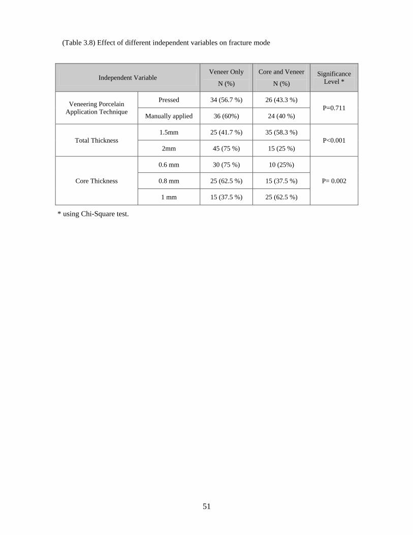
51
(Table 3.8) Effect of different independent variables on fracture mode
Independent Variable Veneer Only
N (%)
Core and Veneer
N (%)
Significance
Level *
Veneering Porcelain
Application Technique
Pressed 34 (56.7 %) 26 (43.3 %)
P=0.711
Manually applied 36 (60%) 24 (40 %)
Total Thickness
1.5mm 25 (41.7 %) 35 (58.3 %)
P<0.001
2mm 45 (75 %) 15 (25 %)
Core Thickness
0.6 mm 30 (75 %) 10 (25%)
P= 0.002 0.8 mm 25 (62.5 %) 15 (37.5 %)
1 mm 15 (37.5 %) 25 (62.5 %)
* using Chi-Square test.
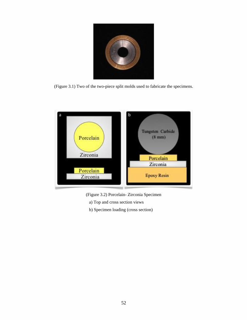
52
(Figure 3.1) Two of the two-piece split molds used to fabricate the specimens.
(Figure 3.2) Porcelain- Zirconia Specimen
a) Top and cross section views
b) Specimen loading (cross section)
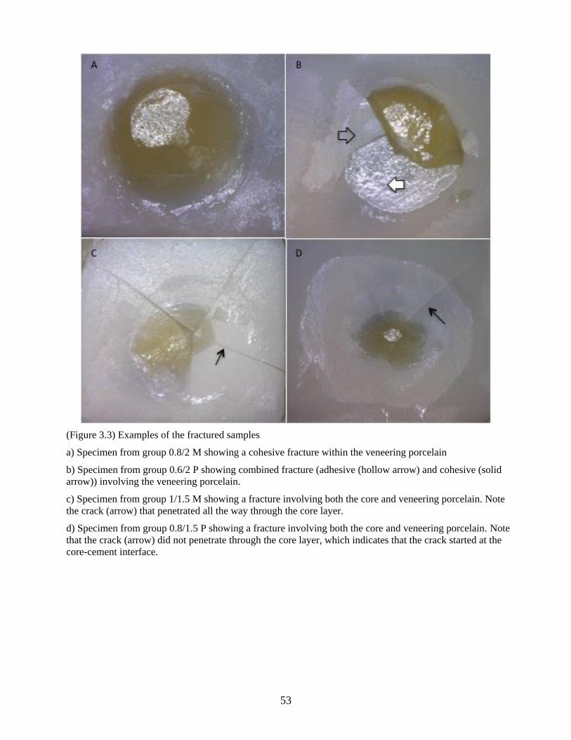
53
(Figure 3.3) Examples of the fractured samples
a) Specimen from group 0.8/2 M showing a cohesive fracture within the veneering porcelain
b) Specimen from group 0.6/2 P showing combined fracture (adhesive (hollow arrow) and cohesive (solid
arrow)) involving the veneering porcelain.
c) Specimen from group 1/1.5 M showing a fracture involving both the core and veneering porcelain. Note
the crack (arrow) that penetrated all the way through the core layer.
d) Specimen from group 0.8/1.5 P showing a fracture involving both the core and veneering porcelain. Note
that the crack (arrow) did not penetrate through the core layer, which indicates that the crack started at the
core-cement interface.
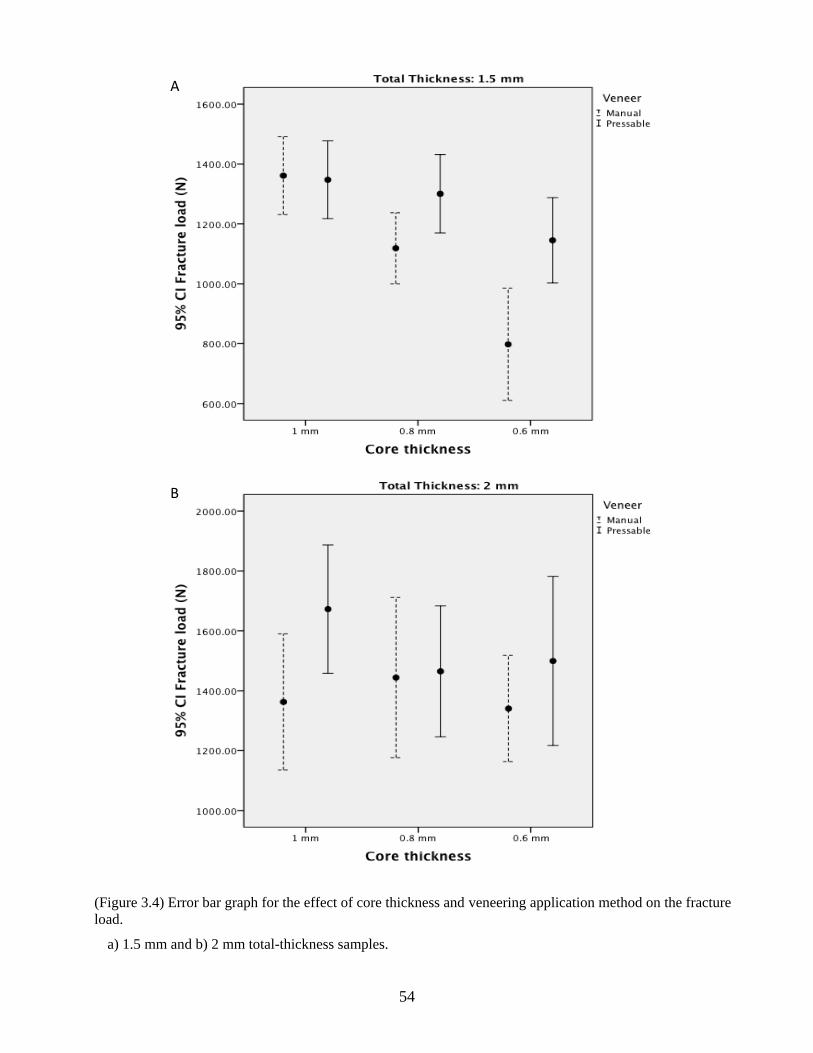
54
(Figure 3.4) Error bar graph for the effect of core thickness and veneering application method on the fracture
load.
a) 1.5 mm and b) 2 mm total-thickness samples.
B
A
55
References
1. Goodacre CJ, Bernal G, Rungcharassaeng K, Kan JY. Clinical complications in
fixed prosthodontics. J Prosthet Dent 2003;90(1):31-41.
2. Kelly JR. Dental ceramics: current thinking and trends. Dent Clin North Am
2004;48(2):viii, 513-viii, 30.
3. Denry I, Kelly JR. State of the art of zirconia for dental applications. Dent Mater
2008;24(3):299-307.
4. Albakry M, Guazzato M, Swain MV. Effect of sandblasting, grinding, polishing
and glazing on the flexural strength of two pressable all-ceramic dental materials.
J Dent 2004;32(2):91-9.
5. Christel P, Meunier A, Heller M, Torre JP, Peille CN. Mechanical properties and
short-term in-vivo evaluation of yttrium-oxide-partially-stabilized zirconia. J
Biomed Mater Res 1989;23(1):45-61.
6. White SN, Miklus VG, McLaren EA, Lang LA, Caputo AA. Flexural strength of
a layered zirconia and porcelain dental all-ceramic system. J Prosthet Dent
2005;94(2):125-31.
7. Raigrodski AJ, Hillstead MB, Meng GK, Chung KH. Survival and complications
of zirconia-based fixed dental prostheses: a systematic review. J Prosthet Dent
2012;107(3):170-7.
8. Cehreli MC, Kokat AM, Akca K. CAD/CAM Zirconia vs. slip-cast glass-
infiltrated Alumina/Zirconia all-ceramic crowns: 2-year results of a randomized
controlled clinical trial. J Appl Oral Sci 2009;17(1):49-55.
9. Heintze SD, Rousson V. Survival of zirconia- and metal-supported fixed dental
prostheses: a systematic review. Int J Prosthodont 2010;23(6):493-502.
10. Ortorp A, Kihl ML, Carlsson GE. A 3-year retrospective and clinical follow-up
study of zirconia single crowns performed in a private practice. J Dent
2009;37(9):731-6.
11. Hosseini M, Worsaae N, Schiodt M, Gotfredsen K. A 1-year randomised
controlled trial comparing zirconia versus metal-ceramic implant supported
single-tooth restorations. Eur J Oral Implantol 2011;4(4):347-61.
12. Rinke S, Schafer S, Roediger M. Complication rate of molar crowns: a practice-
based clinical evaluation. Int J Comput Dent 2011;14(3):203-18.
13. Sagirkaya E, Arikan S, Sadik B, Kara C, Karasoy D, Cehreli M. A randomized,
prospective, open-ended clinical trial of zirconia fixed partial dentures on teeth
and implants: interim results. Int J Prosthodont 2012;25(3):221-31.
14. de Kler M, de Jager N, Meegdes M, van der Zel JM. Influence of thermal
expansion mismatch and fatigue loading on phase changes in porcelain veneered
Y-TZP zirconia discs. J Oral Rehabil 2007;34(11):841-7.
15. Swain MV. Unstable cracking (chipping) of veneering porcelain on all-ceramic
dental crowns and fixed partial dentures. Acta Biomater 2009;5(5):1668-77.
56
16. Tholey MJ, Swain MV, Thiel N. SEM observations of porcelain Y-TZP interface.
Dent Mater 2009;25(7):857-62.
17. Sailer I, Feher A, Filser F, Gauckler LJ, Luthy H, Hammerle CH. Five-year
clinical results of zirconia frameworks for posterior fixed partial dentures. Int J
Prosthodont 2007;20(4):383-8.
18. Raigrodski AJ, Chiche GJ, Potiket N, Hochstedler JL, Mohamed SE, Billiot S, et
al. The efficacy of posterior three-unit zirconium-oxide-based ceramic fixed
partial dental prostheses: a prospective clinical pilot study. J Prosthet Dent
2006;96(4):237-44.
19. Aboushelib MN, de Jager N, Kleverlaan CJ, Feilzer AJ. Microtensile bond
strength of different components of core veneered all-ceramic restorations. Dent
Mater 2005;21(10):984-91.
20. Guess PC, Kulis A, Witkowski S, Wolkewitz M, Zhang Y, Strub JR. Shear bond
strengths between different zirconia cores and veneering ceramics and their
susceptibility to thermocycling. Dent Mater 2008;24(11):1556-67.
21. Aboushelib MN, de Kler M, van der Zel JM, Feilzer AJ. Effect of veneering
method on the fracture and bond strength of bilayered zirconia restorations. Int J
Prosthodont 2008;21(3):237-40.
22. Bonfante EA, da Silva NR, Coelho PG, Bayardo-Gonzalez DE, Thompson VP,
Bonfante G. Effect of framework design on crown failure. Eur J Oral Sci
2009;117(2):194-9.
23. Rosentritt M, Steiger D, Behr M, Handel G, Kolbeck C. Influence of substructure
design and spacer settings on the in vitro performance of molar zirconia crowns. J
Dent 2009;37(12):978-83.
24. Zarone F, Russo S, Sorrentino R. From porcelain-fused-to-metal to zirconia:
clinical and experimental considerations. Dent Mater 2011;27(1):83-96.
25. Neiva G, Yaman P, Dennison JB, Razzoog ME, Lang BR. Resistance to fracture
of three all-ceramic systems. J Esthet Dent 1998;10(2):60-6.
26. Blatz MB. Cementation of zirconium-oxide ceramic restorations. Pract Proced
Aesthet Dent 2004;16(1):14.
27. Kelly JR. Clinically relevant approach to failure testing of all-ceramic
restorations. J Prosthet Dent 1999;81(6):652-61.
28. Lin WS, Ercoli C, Feng C, Morton D. The effect of core material, veneering
porcelain, and fabrication technique on the biaxial flexural strength and weibull
analysis of selected dental ceramics. J Prosthodont 2012;21(5):353-62.
29. Aboushelib MN, Kleverlaan CJ, Feilzer AJ. Microtensile bond strength of
different components of core veneered all-ceramic restorations. Part II: Zirconia
veneering ceramics. Dent Mater 2006;22(9):857-63.
30. Bhowmick S, Melendez-Martinez JJ, Zhang Y, Lawn BR. Design maps for
failure of all-ceramic layer structures in concentrated cyclic loading. Acta Mater
2007;55(7):2479-88.
57
31. Fleming GJ, El-Lakwah SF, Harris JJ, Marquis PM. The effect of core:dentin
thickness ratio on the bi-axial flexure strength and fracture mode and origin of
bilayered dental ceramic composites. Dent Mater 2005;21(2):164-71.
32. Wakabayashi N, Anusavice KJ. Crack initiation modes in bilayered
alumina/porcelain disks as a function of core/veneer thickness ratio and
supporting substrate stiffness. J Dent Res 2000;79(6):1398-404.
33. Mainjot AK, Schajer GS, Vanheusden AJ, Sadoun MJ. Influence of cooling rate
on residual stress profile in veneering ceramic: measurement by hole-drilling.
Dent Mater 2011;27(9):906-14.
34. Mainjot AK, Schajer GS, Vanheusden AJ, Sadoun MJ. Residual stress
measurement in veneering ceramic by hole-drilling. Dent Mater 2011;27(5):439-
44.
35. Mainjot AK, Schajer GS, Vanheusden AJ, Sadoun MJ. Influence of zirconia
framework thickness on residual stress profile in veneering ceramic:
measurement by hole-drilling. Dent Mater 2012;28(4):378-84.
36. Mainjot AK, Schajer GS, Vanheusden AJ, Sadoun MJ. Influence of veneer
thickness on residual stress profile in veneering ceramic: measurement by hole-
drilling. Dent Mater 2012;28(2):160-7.
37. Lawn BR. Fracture of brittle solids. Cambridge solid state science series. 2nd ed.
Cambridge ; New York: Cambridge University Press; 1993. p. 249-306.
58
Chapter 4: Manuscript 2
59
Effect of core thickness and design on fracture strength and fatigue
resistance of zirconia-based crowns
Authors:
Mohammed H. Zahran, BDS, MSc, PhD-candidate
Department of Prosthodontics, Faculty of Dentistry, University of Toronto, Toronto, ON, Canada
Department of Fixed Prosthodontics, Faculty of Dentistry, King Abdulaziz University, Jeddah,
Saudi Arabia
Amin S. Rizkalla, P Eng, PhD
Associate Professor Dentistry, Schulich School of Medicine & Dentistry, The University of
Western Ontario, London, ON, Canada
*Omar El-Mowafy, BDS, PhD, FADM
Professor and Head, Department of Restorative Dentistry, Faculty of Dentistry, University of
Toronto, Toronto, ON, Canada
Asbjorn Jokstad, DDS, PhD
Professor and Head, Department of Prosthodontics, Faculty of Dentistry, University of Toronto,
Toronto, ON, Canada
University of Tromso, Norway
Laura E.Tam, DDS, MSc
Professor, Department of Restorative Dentistry, Faculty of Dentistry, University of Toronto,
Toronto, ON, Canada
*Corresponding author
Omar El-Mowafy, BDS, PhD, FADM
Department of Clinical Sciences
Faculty of Dentistry, University of Toronto
124 Edward Street, Toronto, Ontario M5G 1G6, Canada.
Phone: (416) 979-4934 X 4572
Fax: (416) 979-4936
E-mail: [email protected]
60
Abstract
Purpose: to evaluate the influence of varying the core thickness and modifying the core
design on the fracture strength, mode and extent of zirconia-based crowns and to compare it
to the metal-ceramic crowns. Methods: An ivorine molar was prepared to receive an all-
ceramic crown. Using an epoxy resin, 50 replication dies were made of the prepared tooth.
Forty all-ceramic crowns were made using zirconium-oxide cores (IPS e.max ZirCAD) and
pressed veneering porcelain (IPS e.max Zirpress). All-ceramic crowns were fabricated
according to four different coping designs (n=10/group): 0.6mm even-thickness (group 1),
0.6mm anatomically-shaped (group 2), 1mm even-thickness (group 3), and 1mm
anatomically-shaped (group 4). In addition, ten metal-ceramic crowns were fabricated as
controls. All crowns were cemented to their respective dies using resin cement (PanaviaF
2.0). After water storage, crowns were subjected to cyclic loading in a universal testing
machine (50–600N for 500,000 cycles at 20Hz). After fatigue, crowns were loaded to
fracture at crosshead speed of 0.5 mm/min. Fracture load, mode and extent were recorded.
Data were analyzed using factorial ANOVA and chi-square or Fisher’s exact test at α=0.05.
Results: All the all-ceramic crowns survived the fatigue test, while two metal-ceramic
crowns failed during the fatigue testing. Factorial ANOVA revealed a statistically significant
effect for the core thickness (Mean [SD]: 0.6 mm= 2,543 [716] N and 1mm= 3,061 [816] N),
but not for the core design and the interaction term. Metal-ceramic crowns showed
significantly higher mean fracture load in comparison to group1. All the all-ceramic crowns
except two showed fractures involving the veneering porcelain only. Similarly, all the metal-
ceramic crowns showed fractures involving the veneering layer only with exposure of the
metal copings. Fisher’s exact test revealed no significant effect for the core thickness and
design on the fracture mode. In contrast, core design but not thickness influenced the fracture
extent. Higher percentages of failure involving the axial walls were observed for the even
thickness copings. Conclusions: The core thickness, but not the core design, had a
significant effect on fracture strength of zirconia-based crowns. Anatomically shaped
copings reduced the extent of the veneering porcelain fracture.
Keywords: Fracture strength; fracture mode; zirconium oxide; Zirconia core design;
thickness; crown; ceramics
61
Introduction
The increasing demand for esthetics in combination with health and environmental
concerns of metallic restorations stimulated dental manufacturers and dentists to explore
alternatives such as all-porcelain restorations. However, the clinical performance of all-
ceramic restorations has been short of ideal due, to a great extent, to their inherent
brittleness, which makes them more susceptible to fracture, especially in the posterior
region of the mouth.1,2
In a systematic review on clinical complications in fixed prosthodontics,1 all-ceramic
crowns showed an 8% incidence of complications, with crown fractures being the most
common. Molars showed a higher fracture rate (21%) than premolars and anterior teeth
(7% and 3%, respectively). Kelly reported similar results with higher fracture rates in
posterior crowns compared to anterior crowns.2 This higher fracture rate in the posterior
region can be explained by the higher biting forces in the posterior region (400 to 890 N
in the molar region and 222 to 445 N in the premolar area) in comparison to the anterior
region (133 to 334 N in the cuspid area and 89 to 111 N in the incisor region).3
In the past decade, dental manufacturers have focused their efforts on developing
new all-porcelain products with enhanced mechanical properties to improve their clinical
performance in the posterior region through better resistance to chipping and fracture.
Yttrium-tetragonal zirconia poly-crystals (Y-TZP) is one of these products that has
received special attention due to its high flexural strength and fracture toughness.4 The
tetragonal crystals in these zirconium oxide ceramics are meta-stable and can be
transformed into larger monoclinic crystals with the application of stress from cracks or
flaws.5 This phenomenon is beneficial in hindering crack growth and increasing fracture
toughness; hence, it is referred to as “transformation toughening”.6 However, Y-TZP-
based products cannot provide optimal esthetics because they have high opacity and are
difficult to stain. Therefore, Y-TZP must be used as a core material and clad with
veneering porcelain to enhance esthetics. 7
The improved mechanical properties of zirconia-based restorations were not readily
reflected in their clinical performance with several short-term clinical studies reporting a
high incidence of veneering porcelain chipping with rare framework fractures.8-14
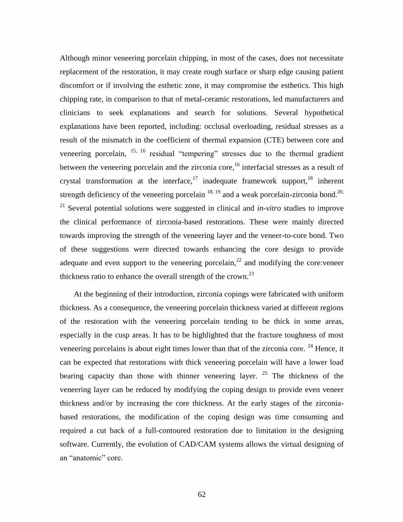
62
Although minor veneering porcelain chipping, in most of the cases, does not necessitate
replacement of the restoration, it may create rough surface or sharp edge causing patient
discomfort or if involving the esthetic zone, it may compromise the esthetics. This high
chipping rate, in comparison to that of metal-ceramic restorations, led manufacturers and
clinicians to seek explanations and search for solutions. Several hypothetical
explanations have been reported, including: occlusal overloading, residual stresses as a
result of the mismatch in the coefficient of thermal expansion (CTE) between core and
veneering porcelain, 15, 16
residual “tempering” stresses due to the thermal gradient
between the veneering porcelain and the zirconia core,16
interfacial stresses as a result of
crystal transformation at the interface,17
inadequate framework support,18
inherent
strength deficiency of the veneering porcelain 18, 19
and a weak porcelain-zirconia bond.20,
21 Several potential solutions were suggested in clinical and in-vitro studies to improve
the clinical performance of zirconia-based restorations. These were mainly directed
towards improving the strength of the veneering layer and the veneer-to-core bond. Two
of these suggestions were directed towards enhancing the core design to provide
adequate and even support to the veneering porcelain,22
and modifying the core:veneer
thickness ratio to enhance the overall strength of the crown.23
At the beginning of their introduction, zirconia copings were fabricated with uniform
thickness. As a consequence, the veneering porcelain thickness varied at different regions
of the restoration with the veneering porcelain tending to be thick in some areas,
especially in the cusp areas. It has to be highlighted that the fracture toughness of most
veneering porcelains is about eight times lower than that of the zirconia core. 24
Hence, it
can be expected that restorations with thick veneering porcelain will have a lower load
bearing capacity than those with thinner veneering layer. 25
The thickness of the
veneering layer can be reduced by modifying the coping design to provide even veneer
thickness and/or by increasing the core thickness. At the early stages of the zirconia-
based restorations, the modification of the coping design was time consuming and
required a cut back of a full-contoured restoration due to limitation in the designing
software. Currently, the evolution of CAD/CAM systems allows the virtual designing of
an “anatomic” core.
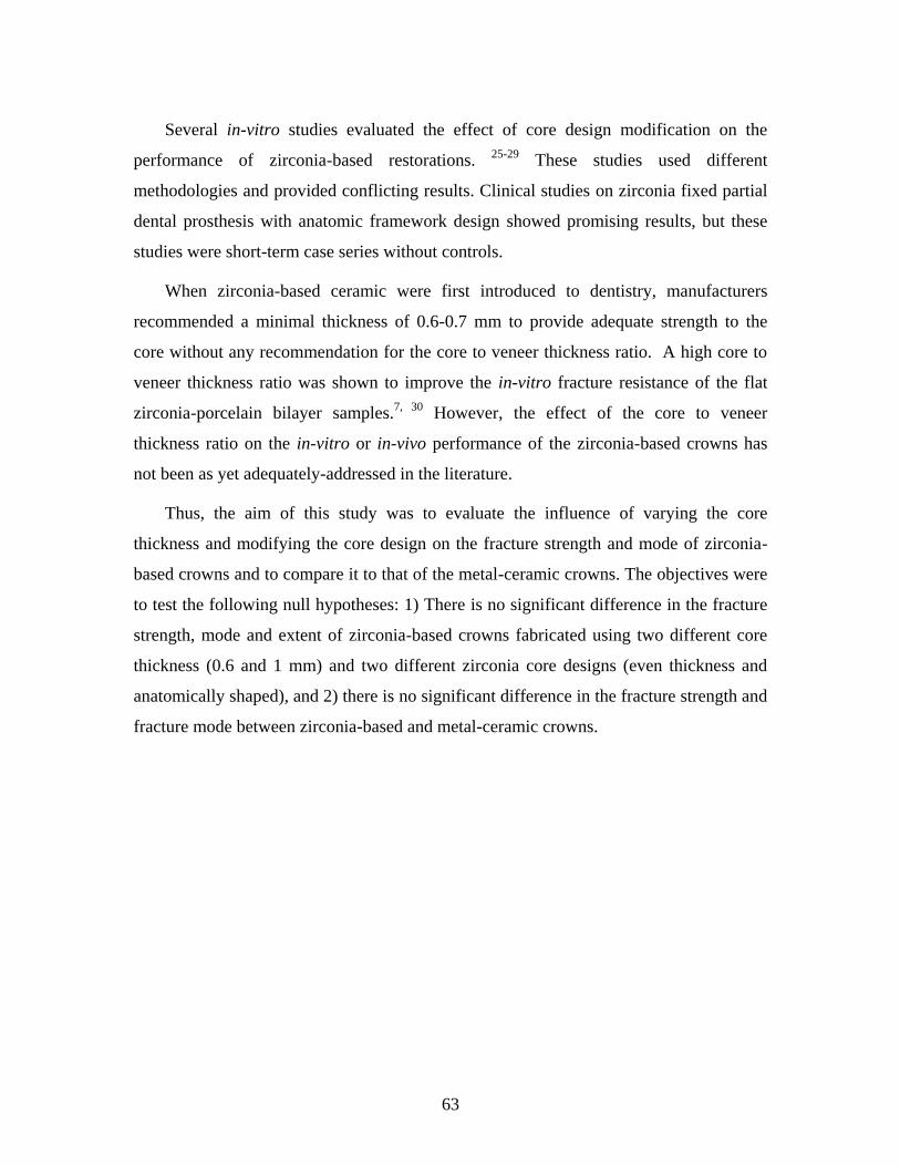
63
Several in-vitro studies evaluated the effect of core design modification on the
performance of zirconia-based restorations. 25-29
These studies used different
methodologies and provided conflicting results. Clinical studies on zirconia fixed partial
dental prosthesis with anatomic framework design showed promising results, but these
studies were short-term case series without controls.
When zirconia-based ceramic were first introduced to dentistry, manufacturers
recommended a minimal thickness of 0.6-0.7 mm to provide adequate strength to the
core without any recommendation for the core to veneer thickness ratio. A high core to
veneer thickness ratio was shown to improve the in-vitro fracture resistance of the flat
zirconia-porcelain bilayer samples.7, 30
However, the effect of the core to veneer
thickness ratio on the in-vitro or in-vivo performance of the zirconia-based crowns has
not been as yet adequately-addressed in the literature.
Thus, the aim of this study was to evaluate the influence of varying the core
thickness and modifying the core design on the fracture strength and mode of zirconia-
based crowns and to compare it to that of the metal-ceramic crowns. The objectives were
to test the following null hypotheses: 1) There is no significant difference in the fracture
strength, mode and extent of zirconia-based crowns fabricated using two different core
thickness (0.6 and 1 mm) and two different zirconia core designs (even thickness and
anatomically shaped), and 2) there is no significant difference in the fracture strength and
fracture mode between zirconia-based and metal-ceramic crowns.
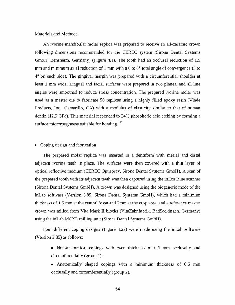
64
Materials and Methods
An ivorine mandibular molar replica was prepared to receive an all-ceramic crown
following dimensions recommended for the CEREC system (Sirona Dental Systems
GmbH, Bensheim, Germany) (Figure 4.1). The tooth had an occlusal reduction of 1.5
mm and minimum axial reduction of 1 mm with a 6 to 8° total angle of convergence (3 to
4° on each side). The gingival margin was prepared with a circumferential shoulder at
least 1 mm wide. Lingual and facial surfaces were prepared in two planes, and all line
angles were smoothed to reduce stress concentration. The prepared ivorine molar was
used as a master die to fabricate 50 replicas using a highly filled epoxy resin (Viade
Products, Inc., Camarillo, CA) with a modulus of elasticity similar to that of human
dentin (12.9 GPa). This material responded to 34% phosphoric acid etching by forming a
surface microroughness suitable for bonding. 31
Coping design and fabrication
The prepared molar replica was inserted in a dentiform with mesial and distal
adjacent ivorine teeth in place. The surfaces were then covered with a thin layer of
optical reflective medium (CEREC Optispray, Sirona Dental Systems GmbH). A scan of
the prepared tooth with its adjacent teeth was then captured using the inEos Blue scanner
(Sirona Dental Systems GmbH). A crown was designed using the biogeneric mode of the
inLab software (Version 3.85, Sirona Dental Systems GmbH), which had a minimum
thickness of 1.5 mm at the central fossa and 2mm at the cusp area, and a reference master
crown was milled from Vita Mark II blocks (VitaZahnfabrik, BadSackingen, Germany)
using the inLab MCXL milling unit (Sirona Dental Systems GmbH).
Four different coping designs (Figure 4.2a) were made using the inLab software
(Version 3.85) as follows:
Non-anatomical copings with even thickness of 0.6 mm occlusally and
circumferentially (group 1).
Anatomically shaped copings with a minimum thickness of 0.6 mm
occlusally and circumferentially (group 2).
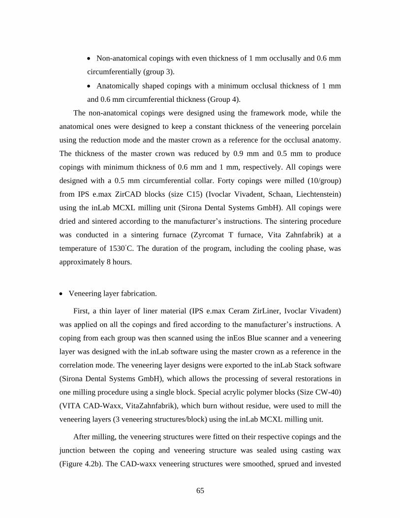
65
Non-anatomical copings with even thickness of 1 mm occlusally and 0.6 mm
circumferentially (group 3).
Anatomically shaped copings with a minimum occlusal thickness of 1 mm
and 0.6 mm circumferential thickness (Group 4).
The non-anatomical copings were designed using the framework mode, while the
anatomical ones were designed to keep a constant thickness of the veneering porcelain
using the reduction mode and the master crown as a reference for the occlusal anatomy.
The thickness of the master crown was reduced by 0.9 mm and 0.5 mm to produce
copings with minimum thickness of 0.6 mm and 1 mm, respectively. All copings were
designed with a 0.5 mm circumferential collar. Forty copings were milled (10/group)
from IPS e.max ZirCAD blocks (size C15) (Ivoclar Vivadent, Schaan, Liechtenstein)
using the inLab MCXL milling unit (Sirona Dental Systems GmbH). All copings were
dried and sintered according to the manufacturer’s instructions. The sintering procedure
was conducted in a sintering furnace (Zyrcomat T furnace, Vita Zahnfabrik) at a
temperature of 1530◦C. The duration of the program, including the cooling phase, was
approximately 8 hours.
Veneering layer fabrication.
First, a thin layer of liner material (IPS e.max Ceram ZirLiner, Ivoclar Vivadent)
was applied on all the copings and fired according to the manufacturer’s instructions. A
coping from each group was then scanned using the inEos Blue scanner and a veneering
layer was designed with the inLab software using the master crown as a reference in the
correlation mode. The veneering layer designs were exported to the inLab Stack software
(Sirona Dental Systems GmbH), which allows the processing of several restorations in
one milling procedure using a single block. Special acrylic polymer blocks (Size CW-40)
(VITA CAD-Waxx, VitaZahnfabrik), which burn without residue, were used to mill the
veneering layers (3 veneering structures/block) using the inLab MCXL milling unit.
After milling, the veneering structures were fitted on their respective copings and the
junction between the coping and veneering structure was sealed using casting wax
(Figure 4.2b). The CAD-waxx veneering structures were smoothed, sprued and invested
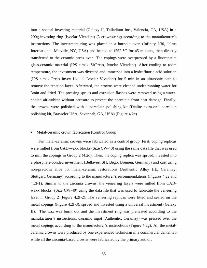
66
into a special investing material (Galaxy II, Talladium Inc., Valencia, CA, USA) in a
200g-investing ring (Ivoclar Vivadent) (3 crowns/ring) according to the manufacturer’s
instructions. The investment ring was placed in a burnout oven (Infinity L30, Jelrus
International, Melville, NY, USA) and heated at 1562 °C for 45 minutes, then directly
transferred to the ceramic press oven. The copings were overpressed by a fluorapatite
glass-ceramic material (IPS e.max ZirPress, Ivoclar Vivadent). After cooling to room
temperature, the investment was divested and immersed into a hydrofluoric acid solution
(IPS e.max Press Invex Liquid, Ivoclar Vivadent) for 5 min in an ultrasonic bath to
remove the reaction layer. Afterward, the crowns were cleaned under running water for
3min and dried. The pressing sprues and extrusion flashes were removed using a water-
cooled air-turbine without pressure to protect the porcelain from heat damage. Finally,
the crowns were polished with a porcelain polishing kit (Dialite extra-oral porcelain
polishing kit, Brasseler USA, Savannah, GA, USA) (Figure 4.2c).
Metal-ceramic crown fabrication (Control Group).
Ten metal-ceramic crowns were fabricated as a control group. First, coping replicas
were milled from CAD-waxx blocks (Size CW-40) using the same data file that was used
to mill the copings in Group 2 (4.2d). Then, the coping replica was sprued, invested into
a phosphate-bonded investment (Bellavest SH, Bego, Bremen, Germany) and cast using
non-precious alloy for metal-ceramic restorations (Authentic Alloy HE; Ceramay,
Stuttgart, Germany) according to the manufacturer’s recommendations (Figures 4.2e and
4.2f-1). Similar to the zirconia crowns, the veneering layers were milled from CAD-
waxx blocks (Size CW-40) using the data file that was used to fabricate the veneering
layer in Group 2 (Figure 4.2f-2). The veneering replicas were fitted and sealed on the
metal copings (Figure 4.2f-3), sprued and invested using a universal investment (Galaxy
II). The wax was burnt out and the investment ring was preheated according to the
manufacturer’s instructions. Ceramic ingot (Authentic, Ceramay) was pressed over the
metal copings according to the manufacturer’s instructions (Figure 4.2g). All the metal-
ceramic crowns were produced by one experienced technician in a commercial dental lab,
while all the zirconia-based crowns were fabricated by the primary author.
67
The details about the materials used in this study and their firing protocol are listed
in Tables 4.1 and 4.2, respectively.
Cementation
Before cementation, the crown thickness at the central fossa was verified to have a
minimum thickness of 1.5 mm using a caliper (Buffalo Dental Manufacturing Co.,
Syosset, NY, USA) and the crown was seated on its respective tooth replica to check its
fit accuracy using a dental explorer (EXD5 explorer, Hu-Friedy, Chicago, IL, USA).
The intaglio surfaces of the all-ceramic crowns were grit blasted for 5 seconds with 50
μm Al2O3 particles using a microetcher under 2 bar pressure at the nozzle. A
bonding/silane coupling agent containing adhesive phosphate monomer (Clearfil SE
bond/Porcelain Bond Activator, Kuraray America Inc., New York, NY, USA) was
applied to the intaglio surfaces of zirconia-based crowns according to the manufacturer’s
recommendations.32
The intaglio surfaces of metal-ceramic crowns were then treated
using an alloy primer (Kuraray America Inc.).
The surfaces of molar replicas were etched using 40% phosphoric acid (Kuraray
America Inc.) for 1 minute. The etched surfaces were cleaned using water spray and
dried using oil-free compressed air.
All crowns were cemented with dual-cured phosphate-modified resin cement
(Panavia F 2, Kuraray America Inc.). ED primer (Kuraray America Inc.) was mixed and
applied evenly to the etched tooth replica surfaces. After 30 seconds, the primer was
dried with compressed air. Panavia F 2 pastes A and B were mixed for 20 seconds and
then applied to the internal surface of the crown. Initially, the crowns were seated on
their respective replicas using finger pressure, the excess cement was removed, and an air
inhibiting gel (Oxyguard, Kuraray America Inc.) was applied to the crown margin for 3
minutes to minimize the formation of the oxygen-inhibited layer at the margin. The
crowns were then placed under static pressure of 2.2 Kg for 5 minutes.33
After removing
the static load, each crown was light cured at the margin (20 seconds for each surface)
using a light curing unit (Optilux 501, Kerr Demetron, Danbury, CT, USA). One hour
after cementation, the crowns were stored in 37˚ C distilled water for 1 week.
68
Mechanical cyclic fatigue and fracture test
All cemented crowns with their respective dies were mounted in resin material (SR
Ivolen, Ivoclar Vivadent) with dimensions suitable for attachment to a loading jig. All
crowns were subjected to mechanical cyclic loading at loads ranging between 50 and 600
N for 500,000 cycles at a frequency of 20 Hz in distilled water at room temperature to
mimic the hydrolytic effect of saliva on the ceramic (static fatigue) using a universal
testing machine (Instron 8501, Instron, Canton, MA, USA). A 5-mm diameter tungsten
carbide ball was used to apply the forces along the long axis of the crown through the
central fossa. The Instron machine was adjusted to stop if the deformation increased
more than 0.15 mm. After cyclic loading, the crowns were examined using magnifying
loupes (X 2.5) for any cracks or fractures. All crowns that passed the cyclic loading
without any evidence of cracks and/or fracture were further subjected to compressive
loading in an Instron machine (Instron 8501) using a cross-head speed of 0.5 mm/min.
Fracture was defined as the occurrence of a sharp drop in the load and confirmed with
acoustic events. At the first sign of fracture, the test was terminated.
The load-displacement data from the Instron machine were imported to a software
program (Microsoft Office Excel, Redmond, WA), and load-displacement curves were
generated. Each curve was carefully analyzed to determine the failure point (the first
sharp drop in the curve) and the corresponding load (N) was recorded as the failure load.
All fractured specimens were examined under magnification (X 2.5) to determine the
mode of fracture (if it involved the veneering porcelain layer alone or both the veneering
porcelain and core layers). In addition, the extent of fracture was classified based on the
extent of the occlusal involvement (involving 50% or less, or more than 50% of the
occlusal surface) and the involvement of any of the axial surfaces (yes or no).
Four zirconia-based crowns were selected (1 from each group) for scanning electron
microscopy (SEM) examination. The crowns were sputter-coated with 7 nm of platinum
in a Polaron E5100 coating unit (Polaron Equipment, Ltd., Bedford, UK) and examined
using SEM (Hitachi S-2500, Hitachi, Mito City, Japan).
69
Statistical Analysis
Two-way analysis of variances (ANOVA) was used to evaluate the effect of core
thickness and core design on fracture strength. One-way ANOVA, followed by Tukey's
test, was used to compare the fracture loads of all groups (including the control). Chi-
square or Fisher’s exact test was used to evaluate the effect of core thickness and design
on the fracture mode and extent.
All statistical analyses were conducted using the SPSS software for Mac (version 20,
SPSS Inc., IBM, Somers, New York, USA). All statistical analyses were two-tailed at a
significance level of (0.05).
70
Results
Fatigue Resistance and Fracture Strength
All zirconia-based crowns passed the cyclic loading without any signs of cracks or
fractures, while two of the metal-ceramic crowns showed signs of cracks or fractures.
Two-way ANOVA revealed significant main effects of the core thickness (P <0.05), but
not for the core design and the interaction term (Table 4.3). The fracture strength of
crowns with 1 mm core thickness (mean [SD]=3061 [816] N) was significantly higher
than the crowns with 0.6 mm core thickness (mean [SD]=2543 [761] N).
One-way ANOVA revealed a statistically significant difference between the groups
(including the metal-ceramic crowns) (P=0.003). Tukey’s post-hoc comparisons
indicated that the fracture strength of both zirconia-based crowns with 1mm anatomical
cores (group 4) and metal-ceramic crowns (control) were statistically higher than the
zirconia-based crowns with 0.6 mm non-anatomical cores (group 1). The fracture
strength data of all groups are summarized in Table 4.4.
Mode and Extent of Fracture
Distributions of the different fracture modes among the groups are shown in Table 4.5.
Except for two, all the zirconia-based crowns (95%) showed a pattern of fracture that
involved the veneering porcelain layer only. Fisher’s exact test revealed no statistically
significant effect of the core thickness and design on the fracture mode of the zirconia-
based crowns (P>0.05). The metal-ceramic crowns revealed similar fracture mode with
all the crowns showing fracture involving the veneering layer only.
Half of the zirconia-based crowns showed fractures involving 50% or less of the
occlusal surface with chi-square test showing no significant difference among the
different core designs and thicknesses. In contrast, about two-thirds of the zirconia-based
crowns showed fracture that involved at least one of the axial surfaces with chi-square or
Fisher’s exact tests showing a statistically significant difference among the different core
designs (P<0.001), but not among the different core thicknesses. Higher percentage of
fractures that involved at least one of the axial surfaces was observed among the
71
zirconia-based crowns with non-anatomical core in comparison to the anatomical ones.
Distribution of the fracture extent data among different independent variables is shown in
Table 4.6. Some examples of the different fractures extent are presented in Figure 4.3.
Half of the metal-ceramic crowns showed fractures that involved more than 50% of
the occlusal surface and only 25% showed axial involvement.
Microscopic examination
The core material showed a homogenous structure compared to the veneering
porcelain where porosities were observed. SEM examination showed that the fracture
originated from the occlusal surface at the loading area and propagated within the
veneering porcelain. At the core-veneer interface, the crack propagated parallel to the
interface (Figure 4.4). It is not clear if the failure at the interface was cohesive within the
veneering porcelain or adhesive at the interface. Some of the SEM pictures revealed
remnants of the veneering porcelain on the core (Figure 4.5). In two of the zirconia-
based crowns, the crack propagated into the core in addition to the veneering porcelain
(Figure 4.6).
Visual examination of the metal-ceramic crowns revealed that all the crowns showed
a combined mode of fracture (cohesively within the veneering porcelain and adhesively
at the metal-ceramic interface (Figure 4.7).
72
Discussion
Despite the limitations of in-vitro studies, they allow the evaluation of individual
factors on the performance of the dental restorations under standardized conditions. In
this study, the recommendations for a clinically-relevant in-vitro load-to-failure test for
all-ceramic restorations described by Kelly were followed,34
including preparing the
teeth according to the clinical guidelines, crown fabrication according to the clinical
standards and with clinically-relevant dimensions, and using a reliable, commonly used
luting cement. The die material used had elastic modulus similar to that of dentin to
avoid variability associated with natural teeth. An aqueous environment was maintained
during cyclic-loading to resemble the effect of water on promoting the crack growth
(static fatigue).2
Clinically, all-ceramic restorations commonly fail through slow crack growth
resulting from fatigue caused by masticatory stresses. The crowns in this study were
fatigued using a range of forces that are clinically-relevant in the molar region. The
crowns were loaded for 500,000 cycles, which represents 10 years of normal function in
the oral cavity,35
or as suggested by Kelly, about half a year of continuous bruxism.34
Our study is unique in terms of examining both the effect of varying core design and
thickness on the in-vitro performance of the zirconia-based crowns. Previous studies
focused on only one of these two factors.25-29, 36
In contrast to the previous studies, no
significant effect of the core design on the fracture strength and fatigue resistance of the
zirconia-based crowns was found in the present study. This dichotomy between the
results of this current study and that of the previous studies can be attributed to different
methodology (including different core designs, materials, core to veneer thickness ratios
and loading protocols). In the present study, the core design was modified occlusally to
provide even support for the veneering layer. Other design modifications were evaluated
in the literature. Recent laboratory work has shown that a modified core design
comprising a high lingual collar connected to high strut at the proximal areas improved
the in-vitro performance of zirconia-based crowns.37-39
Future in-vitro and in-vivo studies
that assess the effect of combining different design modifications on the performance of
the zirconia-based crowns are warranted.
73
In contrast to the core design, core thickness influenced the fracture strength of the
zirconia-based crowns. Results of the present study are in agreement with those of other
studies that favored high core to veneer thickness ratio to improve the fracture strength.7,
30, 36
In the present study, almost all the zirconia-based crowns, except two, showed
fracture mode that involved the veneering layer only without core involvement, which is
expected due to the lower fracture strength and fracture toughness of the veneering
porcelain in comparison to the core. This finding is in harmony with previous clinical
studies, which reported that the cohesive failure within the veneering porcelain is the
chief failure mode for the zirconia-based crowns with the framework fracture seldom
reported.10, 40, 41
In agreement with previous in-vitro studies, core design and thickness
did not affect the fracture mode in this study.25-29, 36
Guazzato et al.42
studied the fracture mode of bilayer porcelain/zirconia samples and
found that fracture initiation occurred through the development of a Hertzian cone crack
at low force. When the force increased, this crack propagated and approached the core
with an acute angle. As the crack reached the core-veneer interface, it was hindered, and
extended laterally parallel to the interface. This lateral extension resulted in delamination
of the veneering porcelain and was followed by crushing of the contact area in 80 % of
the cases. Comparable findings were observed from the fractographic analysis of the
crowns in this study (Figures 4.4 and 4.5) and from examining failed zirconia-based
crowns clinically in a previous report 43
, with the fracture starting at the contact point and
propagating parallel to the interface. As stated previously, visual examination did not
allow the recognition of the fracture nature (cohesive or adhesive) because of the
translucency of the zirliner layer. Some SEM pictures in this current study showed
remnants of veneering material on the core layer. Similar findings were observed in a
previous study.44
The difference of the fracture extent (axially) between the different core designs is in
agreement with previous studies that reported smaller chipping sizes with modified core
designs.26, 44
As stated previously, the crack started at the contact area occlusally and
propagated parallel to the interface. In case of simple even thickness core, the crack is
expected to propagated without any deflection toward the axial surface. In contrast,
74
anatomical cores will deflect the cracks away from the axial surfaces; hence, decreasing
the size and extent of the fracture. It has to be highlighted that such reduced fracture size
translates to a more feasible chairside repair (re-polishing or repair with restoration)
should it occur clinically.
Metal-ceramic crowns were selected as a control in this study because they are
reputed to be the gold standard in dentistry, offering reasonable esthetics45
and long-term
performance.46
The fact that two of the metal-ceramic crowns fractured during fatigue
test might be an indication of their susceptibility to fracture under high occlusal forces.
Goodacre et al.1 reported that porcelain fracture is among the most common
complications for metal-ceramic single crowns at a mean rate of 3% (range between 2.7
and 6%). Despite being a common complication for single crowns, porcelain fracture is
not reported as a significant issue clinically, perhaps because most of the time it is not
noticed by the patient or it is too small in size to cause significant esthetic or functional
concerns.10
In contrast to metal-ceramic restorations, most of the studies that evaluated
the clinical performance of the zirconia-based restoration are short-term and focused
mainly on the fixed partial dental prostheses and not single crowns.10
Although zirconia-
based crowns were introduced as an alternative to metal-ceramic, most of the in-vitro and
in-vivo studies failed to include metal-ceramic as a control. A thorough literature search
identified only two short-term randomized controlled trials (12-18 months) comparing
zirconia-based to metal-ceramic crowns, with comparable performance clinically. 12
13
In the present study, higher mean fracture load was recorded for the metal-ceramic
crowns in comparison to group 1 (0.6 mm even thickness core) but not for the other
groups. This may be attributed to the higher strength of the veneering porcelain used in
the metal-ceramic, the difference in the internal residual stresses within the crowns as a
result of the higher thermal conductivity and lower modulus of elasticity of the metal
alloy in comparison to zirconia and/or improved core-veneer bond. Similar findings were
reported previously using the same zirconia and veneering porcelain but without any
details about the core design.47
Silva et al. 43
reported significantly higher reliability
under mouth-motion cyclic mechanical testing for the metal-ceramic crowns in
comparison to the zirconia-based ones.
75
Similar to the zirconia-based crowns, the metal-ceramic crowns revealed a fracture
mode originating from the occlusal contact area and spreading laterally, with signs of
adhesive fracture and exposure of the metal core, which was easier to identify in
comparison to the zirconia-based crowns due to absence of the opaque layer. Similar
mode of failure was observed previously in-vitro and in-vivo studies. 43, 44
As all loading in the study was vertical and other forces were ignored due to the
loading machine limitations, the clinical implication of the results of the present study
should be interpreted with caution. The use of a higher frequency (20 Hz) in the cyclic
loading test rather than a lower frequency (1 to 2 Hz) as observed in chewing cycles was
unavoidable because of budget limitation. Such high frequency may lead to more heat
generation compared to 1 to 2 Hz, and may not give a time for stress relaxation. Kelly et
al. used 20 Hz frequency for cyclic loading of leucite-reinforced all-ceramic crowns
using a staircase approach between 100 to 600 N, with a 100 N step size for 106 cycles in
water, and was able to measure fracture loads reasonably well for clinical relevance.48
Fracture loads were recorded when there was a sharp drop in the load-displacement
curve accompanied by acoustic sound. However, the load at complete fracture may not
necessarily be the load that the material will withstand before crack initiation. Generally,
crack initiation occurs at a lower force compared to the force required for complete
fracture. Once a crack is initiated, crack propagation starts, leading to complete fracture.
This study did not record the “pop-in” crack (crack initiation) of the specimens because
the crack initiation was not accompanied by any drop in the load, since the loading ball
was entirely supported by the intact specimen surface.
The use of a tungsten carbide loading ball increased the contact pressure in the
specimen compared to the clinical situation as the contact pressure is influenced by the
ratio of the elastic modulus of the porcelain to that of the loading ball, and by the radius
of the loading ball.49
Alternative loading methods could have included the use of a ball
with a modulus of elasticity lower than that of the tungsten carbide one, a tin sheet
between the load applicator and crown as stress breaker, or a stainless steel loading
piston with its end machined to a curvature equivalent to 40-50 mm diameter to
reproduce clinically-relevant contact pressure. However, this increase in the loading
stresses will not affect the comparison between the different test groups since all
76
specimens were loaded using similar contact pressure. Fracture load data reported in this
study should be considered as relative, not absolute values, and extrapolation of these in-
vitro strength data to clinical performance must be considered cautiously and within the
limitations of the study.2
77
Conclusions
This study highlighted the importance of core thickness and design as factors that
can influence the in-vitro performance of the zirconia-based crowns. Both null
hypotheses were partially rejected. The fracture strength and fracture extent were
significantly affected by core thickness and core design, respectively. In addition, metal-
ceramic crowns showed significantly higher mean fracture load in comparison to
zirconia-based crowns with 0.6 mm even-thickness copings. Long term clinical trials are
needed to confirm the findings of this study.
78
Acknowledgements:
This study is part of a PhD thesis submitted to the Faculty of Dentistry, University of
Toronto.
This work was supported by grants from the Faculty of Dentistry Research
Committee, University of Toronto; and Education and Research Foundation of
Prosthodontics. Materials donations were received from Ivoclar-Vivadent and Kuraray;
and technical support provided by Shaw Dental Labs (Toronto) to whom the authors are
grateful.
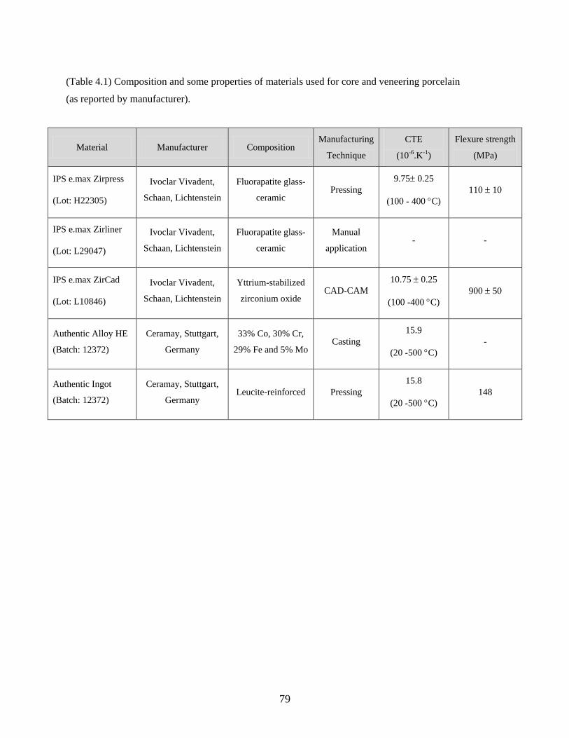
79
(Table 4.1) Composition and some properties of materials used for core and veneering porcelain
(as reported by manufacturer).
Material Manufacturer Composition Manufacturing
Technique
CTE
(10-6.K-1)
Flexure strength
(MPa)
IPS e.max Zirpress
(Lot: H22305)
Ivoclar Vivadent,
Schaan, Lichtenstein
Fluorapatite glass-
ceramic Pressing
9.75 0.25
(100 - 400 C)
110 10
IPS e.max Zirliner
(Lot: L29047)
Ivoclar Vivadent,
Schaan, Lichtenstein
Fluorapatite glass-
ceramic
Manual
application - -
IPS e.max ZirCad
(Lot: L10846)
Ivoclar Vivadent,
Schaan, Lichtenstein
Yttrium-stabilized
zirconium oxide CAD-CAM
10.75 0.25
(100 -400 C)
900 50
Authentic Alloy HE
(Batch: 12372)
Ceramay, Stuttgart,
Germany
33% Co, 30% Cr,
29% Fe and 5% Mo Casting
15.9
(20 -500 C)
-
Authentic Ingot
(Batch: 12372)
Ceramay, Stuttgart,
Germany Leucite-reinforced Pressing
15.8
(20 -500 C)
148
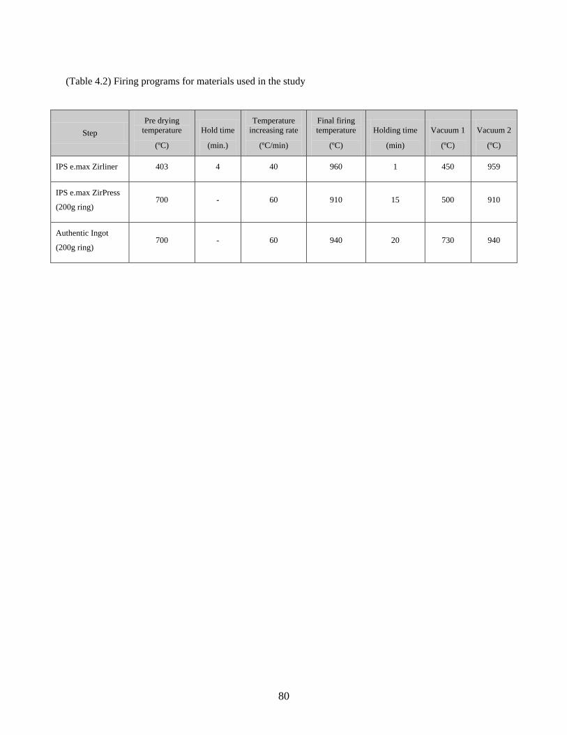
80
(Table 4.2) Firing programs for materials used in the study
Step
Pre drying
temperature
(ºC)
Hold time
(min.)
Temperature
increasing rate
(ºC/min)
Final firing
temperature
(ºC)
Holding time
(min)
Vacuum 1
(ºC)
Vacuum 2
(ºC)
IPS e.max Zirliner 403 4 40 960 1 450 959
IPS e.max ZirPress
(200g ring) 700 - 60 910 15 500 910
Authentic Ingot
(200g ring) 700 - 60 940 20 730 940
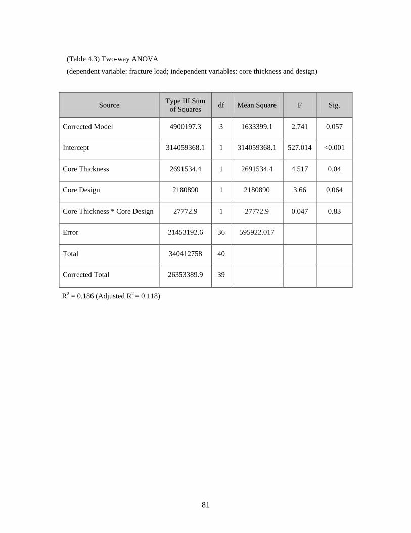
81
(Table 4.3) Two-way ANOVA
(dependent variable: fracture load; independent variables: core thickness and design)
Source Type III Sum
of Squares df Mean Square F Sig.
Corrected Model 4900197.3 3 1633399.1 2.741 0.057
Intercept 314059368.1 1 314059368.1 527.014 <0.001
Core Thickness 2691534.4 1 2691534.4 4.517 0.04
Core Design 2180890 1 2180890 3.66 0.064
Core Thickness * Core Design 27772.9 1 27772.9 0.047 0.83
Error 21453192.6 36 595922.017
Total 340412758 40
Corrected Total 26353389.9 39
R2 = 0.186 (Adjusted R2 = 0.118)
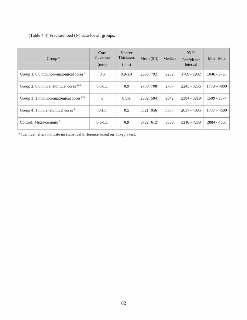
82
(Table 4.4) Fracture load (N) data for all groups.
Group *
Core
Thickness
(mm)
Veneer
Thickness
(mm)
Mean (SD) Median
95 %
Confidence
Interval
Min - Max
Group 1: 0.6 mm non-anatomical cores a 0.6 0.9-1.4 2336 (792) 2232 1769 - 2902 1046 - 3783
Group 2: 0.6 mm anatomical cores a, b 0.6-1.1 0.9 2750 (708) 2767 2243 - 3256 1770 – 4000
Group 3: 1 mm non-anatomical cores a, b 1 0.5-1 2802 (584) 2842 2384 - 3219 1599 - 3574
Group 4: 1 mm anatomical cores b 1-1.5 0.5 3321 (956) 3507 2637 - 4005 1757 – 4500
Control: Metal-ceramic b 0.6-1.1 0.9 3722 (612) 3859 3210 - 4233 2884 - 4500
* Identical letters indicate no statistical difference based on Tukey’s test.
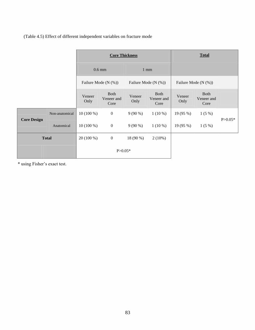
83
(Table 4.5) Effect of different independent variables on fracture mode
Core Thickness Total
0.6 mm 1 mm
Failure Mode (N (%)) Failure Mode (N (%)) Failure Mode (N (%))
Veneer
Only
Both
Veneer and
Core
Veneer
Only
Both
Veneer and
Core
Veneer
Only
Both
Veneer and
Core
Core Design
Non-anatomical 10 (100 %) 0 9 (90 %) 1 (10 %) 19 (95 %) 1 (5 %)
P>0.05*
Anatomical 10 (100 %) 0 9 (90 %) 1 (10 %) 19 (95 %) 1 (5 %)
Total 20 (100 %) 0 18 (90 %) 2 (10%)
P>0.05*
* using Fisher’s exact test.

84
(Table 4.6) Effect of different independent variables on fracture extent
Core
Thickness Core Design
Occlusal involvement
Significance
Level
Axial Fracture
Significance
Level 50% or
less
More than
50% No Yes
0.6 mm
Non-anatomical 3 (30 %) 7 (70 %)
P>0.05*
1 (10 %) 9 (90 %)
P=0.02*
Anatomical 7 (70 %) 3 (30 %) 7 (70 %) 3 (30 %)
1 mm
Non-anatomical 5 (50 %) 5 (50 %)
P>0.05*
0 10 (100 %)
P=0.003**
Anatomical 5 (50 %) 5 (50 %) 7 (70 %) 3 (30 %)
* using chi-square test
** using Fisher’s exact test
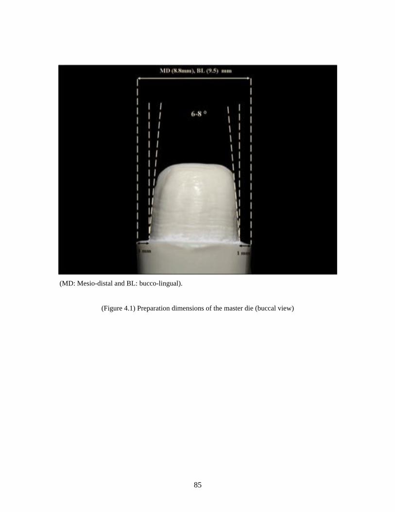
85
(MD: Mesio-distal and BL: bucco-lingual).
(Figure 4.1) Preparation dimensions of the master die (buccal view)
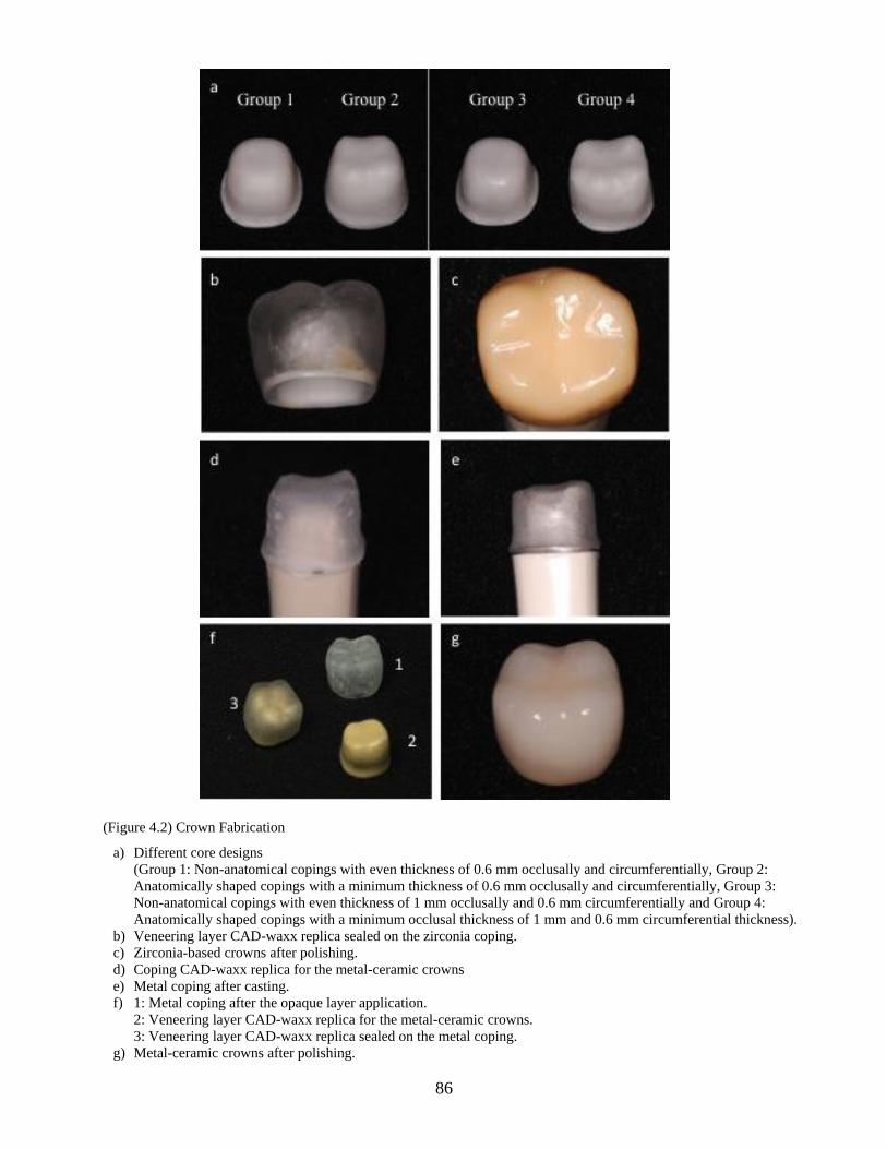
86
(Figure 4.2) Crown Fabrication
a) Different core designs
(Group 1: Non-anatomical copings with even thickness of 0.6 mm occlusally and circumferentially, Group 2:
Anatomically shaped copings with a minimum thickness of 0.6 mm occlusally and circumferentially, Group 3:
Non-anatomical copings with even thickness of 1 mm occlusally and 0.6 mm circumferentially and Group 4:
Anatomically shaped copings with a minimum occlusal thickness of 1 mm and 0.6 mm circumferential thickness).
b) Veneering layer CAD-waxx replica sealed on the zirconia coping.
c) Zirconia-based crowns after polishing.
d) Coping CAD-waxx replica for the metal-ceramic crowns
e) Metal coping after casting.
f) 1: Metal coping after the opaque layer application.
2: Veneering layer CAD-waxx replica for the metal-ceramic crowns.
3: Veneering layer CAD-waxx replica sealed on the metal coping.
g) Metal-ceramic crowns after polishing.
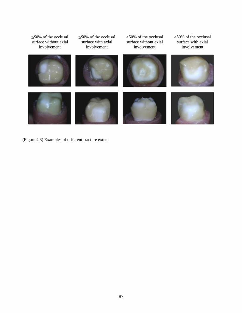
87
(Figure 4.3) Examples of different fracture extent
≤50% of the occlusal
surface without axial
involvement
≤50% of the occlusal
surface with axial
involvement
>50% of the occlusal
surface without axial
involvement
>50% of the occlusal
surface with axial
involvement
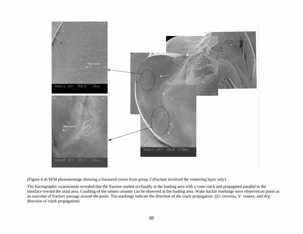
88
(Figure 4.4) SEM photomontage showing a fractured crown from group 2 (fracture involved the veneering layer only).
The fractographic examination revealed that the fracture started occlusally at the loading area with a cone crack and propagated parallel to the
interface toward the axial area. Crushing of the veneer ceramic can be observed at the loading area. Wake hackle markings were observed on pores as
an outcome of fracture passage around the pores. The markings indicate the direction of the crack propagation. (Zr: zirconia, V: veneer, and dcp:
direction of crack propagation)
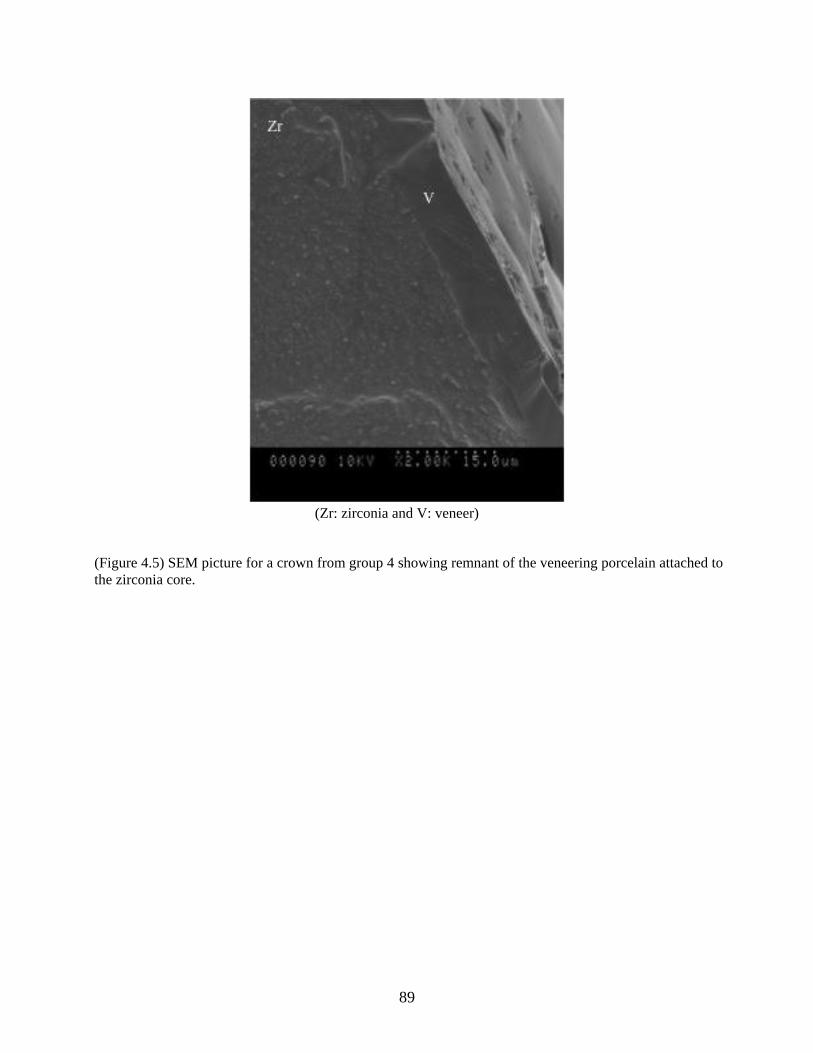
89
(Zr: zirconia and V: veneer)
(Figure 4.5) SEM picture for a crown from group 4 showing remnant of the veneering porcelain attached to
the zirconia core.
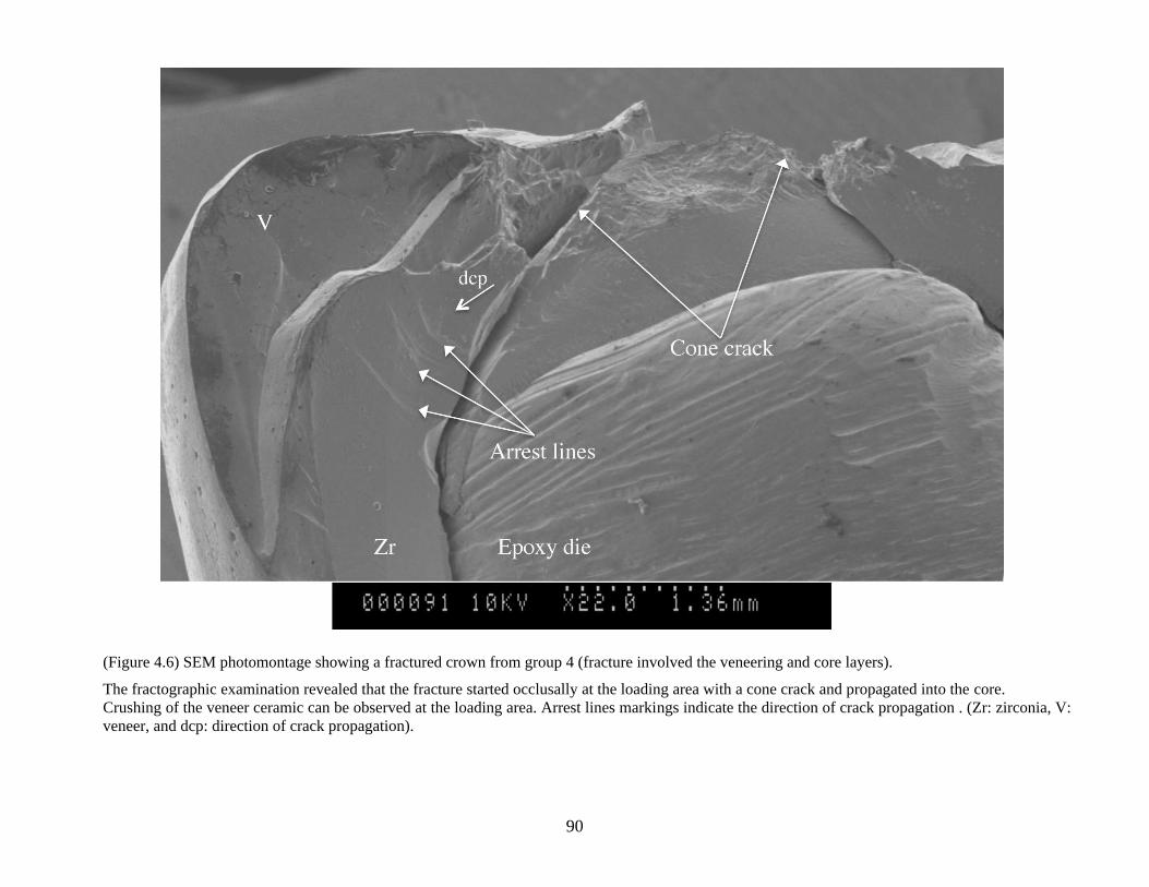
90
(Figure 4.6) SEM photomontage showing a fractured crown from group 4 (fracture involved the veneering and core layers).
The fractographic examination revealed that the fracture started occlusally at the loading area with a cone crack and propagated into the core.
Crushing of the veneer ceramic can be observed at the loading area. Arrest lines markings indicate the direction of crack propagation . (Zr: zirconia, V:
veneer, and dcp: direction of crack propagation).
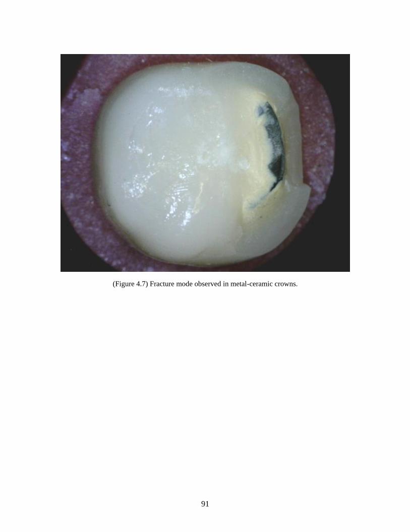
91
(Figure 4.7) Fracture mode observed in metal-ceramic crowns.
92
References
1. Goodacre CJ, Bernal G, Rungcharassaeng K, Kan JY. Clinical complications in
fixed prosthodontics. J Prosthet Dent 2003;90(1):31-41.
2. Kelly JR. Dental ceramics: current thinking and trends. Dent Clin North Am
2004;48(2):viii, 513-viii, 30.
3. Anusavice KJ, Phillips RW. Phillips' science of dental materials. 10th
ed.
Philadelphia: Saunders; 1996. p. 615.
4. Denry I, Kelly JR. State of the art of zirconia for dental applications. Dent Mater
2008;24(3):299-307.
5. Albakry M, Guazzato M, Swain MV. Effect of sandblasting, grinding, polishing
and glazing on the flexural strength of two pressable all-ceramic dental materials.
J Dent 2004;32(2):91-9.
6. Christel P, Meunier A, Heller M, Torre JP, Peille CN. Mechanical properties and
short-term in-vivo evaluation of yttrium-oxide-partially-stabilized zirconia. J
Biomed Mater Res 1989;23(1):45-61.
7. White SN, Miklus VG, McLaren EA, Lang LA, Caputo AA. Flexural strength of
a layered zirconia and porcelain dental all-ceramic system. J Prosthet Dent
2005;94(2):125-31.
8. Raigrodski AJ, Hillstead MB, Meng GK, Chung KH. Survival and complications
of zirconia-based fixed dental prostheses: a systematic review. J Prosthet Dent
2012;107(3):170-7.
9. Cehreli MC, Kokat AM, Akca K. CAD/CAM Zirconia vs. slip-cast glass-
infiltrated Alumina/Zirconia all-ceramic crowns: 2-year results of a randomized
controlled clinical trial. J Appl Oral Sci 2009;17(1):49-55.
10. Heintze SD, Rousson V. Survival of zirconia- and metal-supported fixed dental
prostheses: a systematic review. Int J Prosthodont 2010;23(6):493-502.
11. Ortorp A, Kihl ML, Carlsson GE. A 3-year retrospective and clinical follow-up
study of zirconia single crowns performed in a private practice. J Dent
2009;37(9):731-6.
12. Hosseini M, Worsaae N, Schiodt M, Gotfredsen K. A 1-year randomised
controlled trial comparing zirconia versus metal-ceramic implant supported
single-tooth restorations. Eur J Oral Implantol 2011;4(4):347-61.
13. Rinke S, Schafer S, Roediger M. Complication rate of molar crowns: a practice-
based clinical evaluation. Int J Comput Dent 2011;14(3):203-18.
14. Sagirkaya E, Arikan S, Sadik B, Kara C, Karasoy D, Cehreli M. A randomized,
prospective, open-ended clinical trial of zirconia fixed partial dentures on teeth
and implants: interim results. Int J Prosthodont 2012;25(3):221-31.
93
15. de Kler M, de Jager N, Meegdes M, van der Zel JM. Influence of thermal
expansion mismatch and fatigue loading on phase changes in porcelain veneered
Y-TZP zirconia discs. J Oral Rehabil 2007;34(11):841-7.
16. Swain MV. Unstable cracking (chipping) of veneering porcelain on all-ceramic
dental crowns and fixed partial dentures. Acta Biomater 2009;5(5):1668-77.
17. Tholey MJ, Swain MV, Thiel N. SEM observations of porcelain Y-TZP interface.
Dent Mater 2009;25(7):857-62.
18. Sailer I, Feher A, Filser F, Gauckler LJ, Luthy H, Hammerle CH. Five-year
clinical results of zirconia frameworks for posterior fixed partial dentures. Int J
Prosthodont 2007;20(4):383-8.
19. Raigrodski AJ, Chiche GJ, Potiket N, Hochstedler JL, Mohamed SE, Billiot S, et
al. The efficacy of posterior three-unit zirconium-oxide-based ceramic fixed
partial dental prostheses: a prospective clinical pilot study. J Prosthet Dent
2006;96(4):237-44.
20. Aboushelib MN, de Jager N, Kleverlaan CJ, Feilzer AJ. Microtensile bond
strength of different components of core veneered all-ceramic restorations. Dent
Mater 2005;21(10):984-91.
21. Guess PC, Kulis A, Witkowski S, Wolkewitz M, Zhang Y, Strub JR. Shear bond
strengths between different zirconia cores and veneering ceramics and their
susceptibility to thermocycling. Dent Mater 2008;24(11):1556-67.
22. Marchack BW, Futatsuki Y, Marchack CB, White SN. Customization of milled
zirconia copings for all-ceramic crowns: a clinical report. J Prosthet Dent
2008;99(3):169-73.
23. Zarone F, Russo S, Sorrentino R. From porcelain-fused-to-metal to zirconia:
clinical and experimental considerations. Dent Mater 2011;27(1):83-96.
24. Wang H, Pallav P, Isgro G, Feilzer AJ. Fracture toughness comparison of three
test methods with four dental porcelains. Dent Mater 2007;23(7):905-10.
25. Sundh A, Sjogren G. A comparison of fracture strength of yttrium-oxide-
partially-stabilized zirconia ceramic crowns with varying core thickness, shapes
and veneer ceramics. J.Oral Rehabil. 2004;31(7):682-88.
26. Guess PC, Bonfante EA, Silva NR, Coelho PG, Thompson VP. Effect of core
design and veneering technique on damage and reliability of Y-TZP-supported
crowns. Dent Mater 2013;29(3):307-16.
27. Kokubo Y, Tsumita M, Kano T, Fukushima S. The influence of zirconia coping
designs on the fracture load of all-ceramic molar crowns. Dent Mater J
2011;30(3):281-5.
28. Larsson C, El Madhoun S, Wennerberg A, Vult von Steyern P. Fracture strength
of yttria-stabilized tetragonal zirconia polycrystals crowns with different design:
an in vitro study. Clin Oral Implants Res 2012;23(7):820-6.
94
29. Rosentritt M, Steiger D, Behr M, Handel G, Kolbeck C. Influence of substructure
design and spacer settings on the in vitro performance of molar zirconia crowns. J
Dent 2009;37(12):978-83.
30. Wakabayashi N, Anusavice KJ. Crack initiation modes in bilayered
alumina/porcelain disks as a function of core/veneer thickness ratio and
supporting substrate stiffness. J Dent Res 2000;79(6):1398-404.
31. Neiva G, Yaman P, Dennison JB, Razzoog ME, Lang BR. Resistance to fracture
of three all-ceramic systems. J Esthet Dent 1998;10(2):60-6.
32. Blatz MB. Cementation of zirconium-oxide ceramic restorations. Pract Proced
Aesthet Dent 2004;16(1):14.
33. Pallis K, Griggs JA, Woody RD, Guillen GE, Miller AW. Fracture resistance of
three all-ceramic restorative systems for posterior applications. J Prosthet Dent
2004;91(6):561-9.
34. Kelly JR. Clinically relevant approach to failure testing of all-ceramic
restorations. J Prosthet Dent 1999;81(6):652-61.
35. Wiskott HW, Nicholls JI, Belser UC. Stress fatigue: basic principles and
prosthodontic implications. Int J Prosthodont 1995;8(2):105-16.
36. Alhasanyah A, Vaidyanathan TK, Flinton RJ. Effect of Core Thickness
Differences on Post-Fatigue Indentation Fracture Resistance of Veneered
Zirconia Crowns. J Prosthodont 2013.
37. Bonfante EA, da Silva NR, Coelho PG, Bayardo-Gonzalez DE, Thompson VP,
Bonfante G. Effect of framework design on crown failure. Eur J Oral Sci
2009;117(2):194-9.
38. Bonfante EA, Rafferty B, Zavanelli RA, Silva NR, Rekow ED, Thompson VP, et
al. Thermal/mechanical simulation and laboratory fatigue testing of an alternative
yttria tetragonal zirconia polycrystal core-veneer all-ceramic layered crown
design. Eur J Oral Sci 2010;118(2):202-9.
39. Silva NR, Bonfante EA, Rafferty BT, Zavanelli RA, Rekow ED, Thompson VP,
et al. Modified Y-TZP core design improves all-ceramic crown reliability. J Dent
Res 2011;90(1):104-8.
40. Al-Amleh B, Lyons K, Swain M. Clinical trials in zirconia: a systematic review. J
Oral Rehabil 2010;37(8):641-52.
41. Guess PC, Schultheis S, Bonfante EA, Coelho PG, Ferencz JL, Silva NR. All-
ceramic systems: laboratory and clinical performance. Dent Clin North Am
2011;55(2):333-52, ix.
42. Guazzato M, Proos K, Quach L, Swain MV. Strength, reliability and mode of
fracture of bilayered porcelain/zirconia (Y-TZP) dental ceramics. Biomaterials
2004;25(20):5045-52.
43. Silva NR, Bonfante EA, Zavanelli RA, Thompson VP, Ferencz JL, Coelho PG.
Reliability of metalloceramic and zirconia-based ceramic crowns. J Dent Res
2010;89(10):1051-6.
95
44. Lorenzoni FC, Martins LM, Silva NR, Coelho PG, Guess PC, Bonfante EA, et al.
Fatigue life and failure modes of crowns systems with a modified framework
design. J Dent 2010;38(8):626-34.
45. Donovan TE. Porcelain-fused-to-metal (PFM) alternatives. J Esthet Restor Dent
2009;21(1):4-6.
46. Napankangas R, Raustia A. Twenty-year follow-up of metal-ceramic single
crowns: a retrospective study. Int J Prosthodont 2008;21(4):307-11.
47. Augstin-Panadero R, Fons-Font A, Roman-Rodriguez JL, Granell-Ruiz M, del
Rio-Highsmith J, Sola-Ruiz MF. Zirconia versus metal: a preliminary
comparative analysis of ceramic veneer behavior. Int J Prosthodont
2012;25(3):294-300.
48. Kelly JR, Hunter BD, Brenyo MR, Peterson IM. Simulating clinical failure
during in vitro testing of all-ceramic crowns. J Dent Res 1998;77:778.
49. Lawn BR. Fracture of brittle solids. Cambridge solid state science series. 2nd ed.
Cambridge ; New York: Cambridge University Press; 1993. p. 249-306.
96
Chapter 5: Manuscript 3
97
Effect of core design and veneering material on fracture strength and fatigue
resistance of zirconia molar crowns
Authors:
Mohammed H. Zahran, BDS, MSc, PhD-candidate
Department of Prosthodontics, Faculty of Dentistry, University of Toronto, Toronto, ON, Canada
Department of Fixed Prosthodontics, Faculty of Dentistry, King Abdulaziz University, Jeddah,
Saudi Arabia
*Omar El-Mowafy, BDS, PhD, FADM
Professor and Head, Department of Restorative Dentistry, Faculty of Dentistry, University of
Toronto, Toronto, ON, Canada
Asbjorn Jokstad, DDS, PhD
Professor and Head, Department of Prosthodontics, Faculty of Dentistry, University of Toronto,
Toronto, ON, Canada
Laura E.Tam, DDS, MSc
Professor, Department of Restorative Dentistry, Faculty of Dentistry, University of Toronto,
Toronto, ON, Canada
Amin S. Rizkalla, P Eng, PhD
Associate Professor and Head, Department of Biomaterials Science, Schulich School of Medicine
& Dentistry, The University of Western Ontario, London, ON, Canada
*Corresponding author
Omar El-Mowafy, BDS, PhD, FADM
Department of Clinical Sciences
Faculty of Dentistry, University of Toronto
124 Edward Street, Toronto, Ontario M5G 1G6, Canada.
Phone: (416) 979-4934 X 4572
Fax: (416) 979-4936
E-mail: [email protected]
This work was previously presented in part at the 91st General Session & Exhibition of the IADR,
Seattle, WA, USA in 2013
98
Abstract
Statement of Problem: Chipping of zirconia-based crowns is a common problem.
Purpose: To determine the effect of core design and veneering material on fatigue
resistance and fracture strength of zirconia-based crowns veneered with CAD/CAM
manufactured ceramic. Material and Methods: Forty zirconia cores were fabricated
using uniform thickness or anatomically shaped designs. Cores were veneered using
CAD/CAM manufactured lithium disilicate (IPS e.max CAD) (EMAX) or feldspathic
(Vita Mark II) (VMII) ceramic veneers. Four groups were created by combining different
veneering materials and core designs (n=10). The veneers were connected to the copings
using resin cement or fusion glass-ceramic for the VMII and EMAX crowns, respectively.
All crowns were cemented onto their respective epoxy dies using a resin cement and then
subjected to compressive-mechanical fatigue in a universal testing machine. Specimens
that survived the fatigue test were loaded to fracture at crosshead speed of 1mm/min and
fracture load and mode were recorded. Data were statistically-analyzed using two-way
Analysis of Variance (ANOVA) , and chi-square and Fisher’s exact tests at α=0.05.
Results: All crowns survived the fatigue test without developing cracks or fractures.
Two-way ANOVA revealed a statistically significant effect of the veneering material
(P<0.001) on the fracture load, but not for the core design or the interaction term. The
VMII-veneered crowns showed a lower mean fracture load in comparison to the EMAX -
veneered ones. All VMII-veneered crowns showed fractures involving the veneer only,
while 70% of the EMAX crowns had fractures involving both the core and veneer.
Conclusion: The veneering material, but not the core design, had a significant effect on
fracture load and mode of zirconia-based crowns.
Keywords: Fracture strength; fracture mode: zirconium oxide ceramics; core design;
CAD/CAM
99
Introduction
The increasing demand for esthetics in combination with health and environmental
concerns of metallic restorations stimulated dental manufacturers and dentists to explore
alternatives to metal-ceramic crowns such as all-porcelain ones. However, the clinical
performance of all-ceramic restorations stood short of the ideal due to their inherent
brittleness, which makes them more susceptible to fracture, especially in the posterior
region of the mouth.1,2
In a systematic review on clinical complications in fixed prosthodontics,1 all-ceramic
crowns showed an 8% incidence of complications, with crown fractures being the most
common. Molars showed a higher fracture rate (21%) than premolars and anterior teeth
(7% and 3%, respectively). Kelly reported similar results with higher fracture rates in
posterior crowns compared to anterior crowns.2 This higher fracture rate in the posterior
region can be explained by the higher biting forces in the posterior region (400 to 890 N
in the molar region and 222 to 445 N in the premolar area) in comparison to the anterior
region (133 to 334 N in the cuspid area and 89 to 111 N in the incisor region).3
In the past decade, dental manufacturers have focused their efforts on developing
new all-porcelain products with enhanced mechanical properties to improve their clinical
performance in the posterior region through enhanced resistance to chipping and fracture.
Yttrium-tetragonal zirconia poly-crystals (Y-TZP) is one of these products that has
received special attention due to its high flexural strength and fracture toughness.4 The
tetragonal crystals in these zirconium oxide ceramics are meta-stable and can be
transformed into larger monoclinic crystals with the application of stress from cracks or
flaws.5 This phenomenon is beneficial in hindering crack growth and increasing fracture
toughness; hence, it is referred to as “transformation toughening”.6 However, Y-TZP-
based products cannot provide optimal esthetics because they possess high opacity and
are difficult to stain. Therefore, Y-TZP must be used as a core material and clad with
veneering porcelain to enhance esthetics. 7
At the early stages in the history of zirconia-based crowns, veneering porcelain was
layered manually on the core material and sintered similar to metal-ceramic crowns. The
improved mechanical properties of Y-TZP -based restorations were not readily reflected
100
in their clinical performance with several short-term clinical studies reporting a high
incidence of veneering porcelain chipping with rare framework fractures.8-14
Although
minor veneering porcelain chipping, in most of the cases, does not necessitate
replacement of the restoration, it may create a rough surface or sharp edge causing
patient discomfort or if involving the esthetic zone, it may compromise the esthetics.
This high chipping rate, in comparison to that of metal-ceramic restorations may be
caused by: occlusal overloading, residual stresses as a result of the mismatch in the
coefficient of thermal expansion (CTE) between core and veneering porcelain, 15, 16
residual “tempering” stresses due to the thermal gradient between the veneering
porcelain and the zirconia core,16
interfacial stresses as a result of crystal transformation
at the interface,17
inadequate framework support,18
inherent strength deficiency of the
veneering porcelain 18, 19
and a weak porcelain-zirconia bond.20, 21
Several potential
solutions were suggested in clinical and in-vitro studies to improve the clinical
performance of zirconia-based restorations. These were mainly directed towards
improving the strength of the veneering layer and the veneer-to-core bond. Two of these
suggestions were directed towards enhancing the core design to provide adequate and
even support to the veneering porcelain,22
and improving the strength of the veneering
layer. 23, 24
In general, the ability of ceramic material to withstand occlusal forces is
compromised by the presence of two types of inherent flaws25
: fabrication defects
(internal voids, porosities or microstructural features which arise during processing) and
surface cracks (defects on the surface as a result of machining and grinding process).26
Failure begins with microscopic damage that results from the interaction of preexisting
defects with applied loads.25
Failure can also occur because of impact forces or
subcritical crack growth,27, 28
which is enhanced in an aqueous environment.29
Thus, it is
expected that reducing the flaws and voids within the veneering material may result in
better mechanical properties.
In comparison to the manual layering, heat pressed veneering materials with thermal
properties compatible with the zirconium oxide cores improved the strength and the
interfacial bond between the veneering porcelain and zirconia.23
This improvement was
reflected in the clinical performance of zirconia-based restorations with short-term
101
clinical studies showing significantly less veneer chipping for pressed veneering
porcelain than for manually applied veneering porcelain.10
Unfortunately, the
improvement in the performance of the veneering layer is limited by the flexural strength
of the veneering layer, which is generally less than 125 MPa.30, 31
A potential alternative route is to fabricate the veneering and core layers
independently by means of CAD/CAM technology using industrially fabricated ceramic
blocks and then join them using fusion ceramic or adhesive cement.32, 33
This approach
simplifies the fabrication process, saves time by eliminating time-consuming hand-
layering, drying, and fusing processes, and allows the use of high strength ceramic that is
free from processing flaws as a veneering layer, which is expected to improve the
strength of the zirconia-based restorations. IPS e.max CAD-on (Ivoclar Vivadent,
Schaan, Liechtenstein) and Vita Rapid Layer (VitaZahnfabrik, BadSackingen, Germany)
use lithium disilicate (IPS e.max CAD, Ivoclar Vivadent) and feldspathic (Vita Mark II,
VitaZahnfabrik) blocks, respectively, to produce the veneering layer for all-ceramic
zirconia-based restorations using CEREC system (Sirona Dental Systems GmbH,
Bensheim, Germany). In both techniques, the core and the veneering layers are designed
and fabricated using the CAD-CAM technology and connected using a resin cement (for
the rapid layering technique) and a fusion glass-ceramic (for the CAD-on technique).
Several in-vitro studies evaluated the effect of core design modification as a factor
that might influence the performance of zirconia-based restorations. 34-38
These studies
used different methodologies and provided conflicting results. Clinical studies on
zirconia fixed partial dentures with anatomic framework design showed promising results,
but these studies were short-term case series without controls.39, 40
Thus, the aim of this study was to evaluate the influence of different core designs
and veneering materials on the fatigue resistance, fracture strength and fracture mode of
CAD-CAM zirconia-based crowns. The objective was to test the following null
hypothesis: There is no significant difference in fatigue resistance, fracture strength and
fracture mode of zirconia-based crowns fabricated using two different zirconia core
designs (uniform thickness and anatomically shaped) and two veneering materials (IPS
e.max CAD and Vita Mark II).
102
Material and Methods
Preparation
An ivorine mandibular molar replica was prepared to receive an all-ceramic crown
following dimensions recommended for the CEREC system (Sirona Dental Systems
GmbH, Bensheim, Germany) (Figure 5.1). The tooth had an occlusal reduction of 1.5
mm and minimum axial reduction of 1 mm with a 6 to 8° total angle of convergence (3 to
4° on each side). The gingival margin was prepared with a circumferential shoulder at
least 1 mm wide. Lingual and facial surfaces were prepared in two planes, and all line
angles were smoothed to reduce stress concentration. The prepared ivorine molar was
used as a master die to fabricate 40 replicas using a highly filled epoxy resin (Viade
Products, Inc., Camarillo, CA) with a modulus of elasticity similar to that of human
dentin (12.9 GPa). This material responded to 34% phosphoric acid etching by forming
surface microroughness suitable for bonding. 41
Coping design and fabrication
The prepared molar replica was inserted in a dentiform with mesial and distal
adjacent ivorine teeth in place. The surfaces were then covered with a thin layer of
optical reflective medium (CEREC Optispray, Sirona Dental Systems GmbH). A scan of
the prepared tooth with its adjacent teeth was then captured using the inEos Blue scanner
(Sirona Dental Systems GmbH). A reference master crown, which had a minimum
thickness of 1.5 mm at the central fossa and 2mm at the cusp area, was designed and
milled using the biogeneric mode of the inLab software (Version 3.85, Sirona Dental
Systems GmbH), and Vita Mark II blocks (VitaZahnfabrik, BadSackingen, Germany)
using the inLab MCXL milling unit (Sirona Dental Systems GmbH).
Two different coping designs (Figures 5.2a, 5.2b and 5.2c) were used with the inLab
software (Version 3.85) as follows:
Non-anatomical copings with a uniform thickness of 0.6 mm occlusally and
circumferentially (group 1).
103
Anatomically-shaped copings with a minimum thickness of 0.6 mm
occlusally and circumferential (group 2).
The non-anatomical copings were designed using the multilayer mode. In this mode,
a fully anatomical crown was designed first using the master crown as a reference for the
occlusal anatomy. Then, the inLab software automatically split the design file into two
separate files for the core and veneer layers. The software produced a non-anatomical
copings design with a predefined thickness of 0.6 mm and did not allow any modification
of the design. Due to this limitation, a different designing mode (reduction mode) was
used to design the anatomical copings using the master crown as a reference for the
occlusal anatomy. The thickness of the master crown was reduced by 0.9 mm to produce
anatomical copings with minimum thickness of 0.6 mm. All copings were designed with
a 0.5 mm circumferential collar and milled from Y-TZP (IPS e.max ZirCAD blocks, size
C15, Ivoclar Vivadent) using the inLab MCXL milling unit (Sirona Dental Systems
GmbH). All copings were dried and sintered according to the manufacturer’s instructions.
The sintering procedure was conducted in a sintering furnace (Programat S1, Ivoclar
Vivadent) at a temperature of 1530◦C. The duration of the program, including the cooling
phase, was approximately 90 minutes.
Veneering layer fabrication.
The copings were veneered using CAD/CAM manufactured lithium disilicate (IPS
e.max CAD) (EMAX) or feldspathic (Vita Mark II) (VMII) ceramic veneers. The
multilayer mode was used to design the veneering layer for the non-anatomical copings
with a minimal of 0.9 mm at the central fossa. Different designing mode was used to
design the veneering layer for the anatomical copings. First, one of the anatomical
copings was inserted on the prepared molar replica. Then, the surfaces of the copings
were covered with a thin layer of optical reflective medium (CEREC Optispray) and
scanned using the inEos Blue scanner. The inLab software was used to design the
veneering layer with a uniform thickness of 0.9 mm using the master crown as reference
for the occlusal anatomy. The veneering layers were milled using EMAX and the VMII
blocks in the inLab MCXL milling unit. After milling, the copings from each design
104
were randomly assigned to two veneering materials (n=10) and each veneering layer was
fitted on its respective coping.
Crown fabrication.
All the crowns in this study were fabricated by the primary author to eliminate
variability.
The VMII veneering layers were glazed using Vita Glaze-LT (Vita Zahnfabrik)
according to the manufacturer’s instructions using a porcelain furnace (Vita vacumat
4000 premium T, Vita Zahnfabrik) (5.2d). The intaglio surfaces were treated with 5%
hydrofluoric acid-etching gel (Ivoclar Vivadent) for 20 seconds. The etched internal
surfaces were rinsed with water spray, followed by ultrasonic cleaning in distilled water
for 60 seconds. A bonding/silane coupling agent containing adhesive phosphate
monomer (Clearfil SE bond/porcelain bond activator, Kuraray America, Inc.) was then
applied to the intaglio surfaces of the VM II veneers. The external surfaces of the
zirconia copings were grit-blasted for 5 seconds with 50 μm Al2O3 particles using a
microetcher under 2.5 bar pressure.
The VM II veneering layers were cemented onto their respective copings with dual-
polymerized phosphate-modified resin cement (Panavia F 2.0, Kuraray America, Inc.)
according to manufacturer’s instructions. The veneers were seated on their respective
copings using finger pressure, the excess cement was removed, an air-sealing gel
(Oxyguard, Kuraray America, Inc.) was applied to the junction between the coping and
the veneering layer for 3 minutes, and then each crown was light-polymerized (Optilux
501, Kerr Demetron, Danbury, CT) for 20 seconds on each surface.
The EMAX veneers (Figure 5.2e) were fused to their respective copings using a
fusion glass-ceramic material (IPS e.max CAD Crystall/Connect, Ivoclar Vivadent),
which was applied to the intaglio veneer surfaces and dispersed using a vibration device
(Ivomix, Ivoclar Vivadent). The copings were seated on the veneering layer using finger
pressure and the Ivomix device, which turns the fusion glass-ceramic mass into a
flowable material, and the excess fusion material was removed. The crowns were cleaned
with a brush and glaze was applied (IPS e.max CAD Crystall./glaze, Ivoclar Vivadent)
105
(Figure 5.2f). The fusion and crystallization firing as well as the glaze firing were
completed according to the manufacturer’s recommendations in a porcelain furnace
(Programat P500, Ivocalr Vivadent).
Details about the materials used in this study and their firing protocols are listed in
Tables 5.1 and 5.2, respectively.
Crown cementation
Before cementation, the crown thickness at the central fossa was verified to be 1.5
mm using a caliper (Buffalo Dental Manufacturing Co., Syosset, NY, USA) and the
crown was seated on its respective tooth replica to check its fit accuracy using a dental
explorer (EXD5 explorer, Hu-Friedy, Chicago, IL, USA).
The intaglio surfaces of the crowns were grit blasted for 5 seconds with 50 μm Al2O3
particles using a microetcher under 2 bar pressure at the nozzle. A bonding/silane
coupling agent containing adhesive phosphate monomer (Clearfil SE bond/Porcelain
Bond Activator, Kuraray America Inc., New York, NY, USA) was applied to the intaglio
surfaces of zirconia-based crowns according to the manufacturer’s recommendations.42
The surfaces of molar replicas were etched using 40% phosphoric acid (Kuraray
America Inc.) for 1 minute. The etched surfaces were cleaned using water spray and
dried using oil-free compressed air.
All crowns were cemented with dual-cured phosphate-modified resin cement
(Panavia F 2.0, Kuraray America Inc.) according to the manufacturer’s instructions. ED
primer (Kuraray America Inc.) was mixed and applied evenly to the etched tooth replica
surfaces. After 30 seconds, the primer was dried with compressed air. Panavia F 2.0
pastes A and B were mixed for 20 seconds and then applied to the internal surface of the
crown. Initially, the crowns were seated on their respective replicas using finger pressure,
the excess cement was removed, and the air inhibiting gel (Oxyguard, Kuraray America
Inc.) was applied to the crown margin for 3 minutes. The crowns were then placed under
static pressure of 2.2 Kg for 5 minutes.43
After removing the static load, each crown was
light cured at the margin (20 seconds for each surface) using a light curing unit (Optilux
106
501, Kerr Demetron, Danbury, CT, USA). One hour after cementation, the crowns were
stored in 37˚ C distilled water for 1 week.
Mechanical cyclic fatigue and fracture test
All cemented crowns with their respective dies were mounted in resin material (SR
Ivolen, Ivoclar Vivadent) with dimensions suitable for attachment to a loading jig.
Crowns were subjected to compressive cyclic loading with a load cycle of 50 and 600 N
for 500,000 cycles at a frequency of 20 Hz in distilled water at room temperature (Instron
8872, Instron, Canton, MA, USA). This was followed in order to mimic the hydrolytic
effect of saliva on the ceramic (static fatigue). A 5-mm diameter tungsten carbide ball
was used to apply the forces uniaxially through the central fossa. The Instron machine
was adjusted to stop if the deformation increased more than 0.15 mm. After cyclic
loading, the crowns were examined using magnifying loupes (X 2.5) for any cracks or
fractures. All crowns that passed the cyclic loading test without any evidence of cracks
and/or fracture were uniaxially-loaded in a universal testing machine (Instron 3345,
Instron) using a cross-head speed of 0.5 mm/min to fracture. Fracture was defined as the
occurrence of a sharp drop in the load and confirmed with acoustic events. At the first
sign of fracture, the test was terminated and the corresponding load (N) was recorded as
the failure load.
All fractured specimens were examined using magnifying loupes (X 2.5) to
determine the mode of fracture (if it involved the veneering porcelain layer alone or both
the veneering porcelain and core layers).
Two of the CAD crowns, representing different fracture modes, were selected for
scanning electron microscopy (SEM) examination. The crowns were sputter-coated with
7 nm of platinum in a Polaron E5100 coating unit (Polaron Equipment, Ltd., Bedford,
UK) and examined using SEM (Hitachi S-2500, Hitachi, Mito City, Japan).
107
Statistical Analyses
Two-way analysis of variances (ANOVA) was used to evaluate the effect of core
design and veneering layer material on fracture load, while Chi-square or Fisher’s exact
test was used to evaluate the effect of veneering material and core design on the fracture
mode.
All statistical analyses were conducted using the SPSS software for Mac (version 20,
SPSS Inc., IBM, Somers, New York, USA). All statistical analyses were two-tailed at a
significance level of (0.05).

108
Results
Fracture Mode
Distributions of the different fracture modes among the groups are shown in Table
5.3. All the VMII crowns showed a pattern of fracture that involved the veneering
porcelain layer only (Figure 5.3a), while only 30% of the EMAX crowns showed similar
fracture mode (Figure 5.3b) with the majority of the EMAX crowns showing a fracture
mode that involved both the veneer and core layers (Figure 5.3c). Chi-square test
revealed no statistically significant effect of the core design, but a significant effect of the
veneering material on the fracture mode.
Fatigue Resistance and Fracture Load
All crowns passed the cyclic loading test without any signs of cracks or fractures.
Two-way ANOVA revealed a significant main effect of the veneering layer (P <0.001),
but not for the core design or the interaction term (Table 5.4). Mean fracture strengths of
the EMAX crowns (mean [SD]=3545 [1116] N, 95% CI: 3022 - 4067) were significantly
higher than those of the VMII crowns (mean [SD]=2016 [434] N, 95% CI: 1813 - 2219).
The fracture strength data of all groups are summarized in Table 5.3.
Because EMAX crowns showed different fracture modes, the fracture strength data
were examined according the fracture mode (Table 5.5). The mean fracture load for the
crowns that showed fractures involving the veneering layer only was lower than the
crowns that showed fractures involving both the core and veneer layers, however, data
were overlapping between both fracture modes.
Microscopic examination
In this study, both veneering materials showed more homogenous structures with
less flaws and porosity in comparison to the manually-applied and pressed veneering
porcelain as observed in previous studies.44, 45
SEM examination showed some flaws at
the interface between the fusion ceramic and the core material (Figure 5.4). Visual and
SEM examinations showed that the fracture originated from the occlusal surface at the
109
loading area and propagated within the veneering porcelain for both veneer layer
materials (Figure 5.5). SEM photos revealed no obvious signs of crack penetration
through the interface toward the zirconia, which may indicate that the core fracture that
was observed in the majority of the EMAX crowns was due to radial cracks starting at
the cement-core interface.
110
Discussion
Despite the limitations of in-vitro studies, they allow the evaluation of individual
factors on the performance of the dental restorations under standardized conditions. In
this study, the recommendations for a clinically-relevant in-vitro load-to-failure test for
all-ceramic restorations described by Kelly were followed,46
including preparing the
teeth according to the clinical guidelines, crown fabrication according to the clinical
standards and with clinically-relevant dimensions, and using a reliable, commonly used
luting cement. The die material used had elastic modulus similar to that of dentin to
avoid variability associated with natural teeth. An aqueous environment was maintained
during cyclic-loading to resemble the effect of water on promoting the crack growth
(static fatigue).2
Clinically, all-ceramic restorations commonly fail through slow crack growth
resulting from fatigue caused by masticatory stresses. The crowns in this study were
fatigued using a range of forces that are clinically-relevant in the molar region. The
crowns were loaded for 500,000 cycles, which represents 10 years of normal function in
the oral cavity,47
or as suggested by Kelly, about half a year of continuous bruxism.46
In contrast to the previous studies, no significant effect of the core design on the
fracture load of the zirconia-based crowns was found in the present study. 34-38, 48
This
dichotomy between the results of the current study and those of the previous studies can
be attributed to different methodology (including different core designs, materials, core
to veneer thickness ratios and loading protocols). Our group observed similar finding in a
previous study (unpublished data) using similar methodology (including similar core
design, crown dimensions and loading protocol), but pressed veneering porcelain.
Crowns made using the EMAX veneer material showed higher mean fracture load in
comparison to VMII. This result was expected due to the improved mechanical
properties of the lithium disilicate in comparison to feldspathic ceramic (Table 5.1). The
different methods for joining the VMII and EMAX veneers to the cores may also have
contributed to the different fracture strength results for these groups.
In the present study, different fracture modes were observed between the different
veneering layer materials and a trend of a greater incidence of both veneer and core
111
fracture mode occurring with higher fracture loads was observed. While all the VMII
crowns showed fractures that involved the veneering layer only without core
involvement, about 70% of the EMAX crowns showed fractures involving both core and
veneer layers. The involvement of both layers in the EMAX crowns reflects a
competition between the cone crack within the veneer layer and radial crack from the
undersurface of the core layer. The increase in the strength and fracture toughness of the
EMAX veneer material over the VMII material resulted in an increase of the critical load
for the cone cracking relative to the radial cracking, which rendered the crowns more
susceptible to radial cracking of the core layer 49
. One of the advantages of adhesive
joining of the veneer and core layers is the elimination of residual thermal stresses within
the veneering layer that can be generated as a result of thermal gradients occurring during
the cooling of the veneer during fabrication, and the mismatch in thermal expansion
properties between the core and veneering porcelain.50
This advantage might have been
masked in this study as a result of the differences in the mechanical properties of the used
veneering ceramics. Future in-vitro studies that evaluate the effect of joining lithium
disilicate to zirconia core using adhesive cement or fusion ceramic on the fracture
strength and mode are warranted.
The use of adhesive cement to bond the veneer and core layers may act as a weak
interface that is subject to chemical degradation. It was shown that the adhesive cement
provides an internal barrier to crack propagation from one layer to the next, leading to
fracture modes including delamination at the interface and radial cracking at the bottom
of the flexing veneer layer.32
In the present study, cone cracks were observed within all
the VMII layers (rapid layering technique) (Figure 5.3a). It is not clear whether the
failure of the crown resulted from these cone cracks or other radial cracks at the
undersurface of the veneering layer. Hermann et al.51
evaluated the effect of cyclic
loading on the failure mode of glass-zirconia bilayered specimens and reported that cone
crack was the cause of failure in most of the cases. In contrast, Lee et al. 32
reported that
radial cracking is the cause of failure for the most of the glass-zirconia bilayered
specimens subjected to load to failure test.
Since loading in the study was vertical and other forces that are generated during
mastication were not replicated due to the loading machine limitations, the clinical
112
implication of the results of the present study should be interpreted with caution. The use
of a higher frequency (20 Hz) in the cyclic loading test rather than a lower frequency (1
to 2 Hz) as observed in chewing cycles was unavoidable because of budget limitations.
Such high frequency may lead to more heat generation compared to 1 to 2 Hz, and may
not allow sufficient time for stress relaxation. Kelly et al. used 20 Hz frequency for
cyclic loading of leucite-reinforced all-ceramic crowns using a staircase approach
between 100 to 600 N, with a 100 N step size for 106 cycles in water, and was able to
measure fracture loads reasonably well for clinical relevance.52
Fracture loads were recorded when there was a sharp drop in the load-displacement
curve accompanied by acoustic sound. However, the load at complete fracture may not
necessarily be the load that the material will withstand before crack initiation. Generally,
crack initiation occurs at a lower force compared to the force required for complete
fracture. Once a crack is initiated, crack propagation starts, leading to complete fracture.
This study did not record the “pop-in” crack (crack initiation) of the specimens because
the crack initiation was not accompanied by any drop in the load, since the loading ball
was entirely supported by the intact specimen surface.
The use of a tungsten carbide loading ball increased the contact pressure in the
specimen compared to the clinical situation as the contact pressure is influenced by the
ratio of the elastic modulus of the porcelain to that of the loading ball, and by the radius
of the loading ball.53
Alternative loading methods could have included the use of a ball
with a modulus of elasticity lower than that of the tungsten carbide one, a tin sheet
between the load applicator and crown as stress breaker, or a stainless steel loading
piston with its end machined to a curvature equivalent to 40-50 mm diameter to
reproduce clinically-relevant contact pressure. However, the increase in the loading
stresses of the tungsten ball would not have significantly affect the comparison between
the different test groups since all specimens were loaded using similar contact pressure.
Fracture load data reported in this study should be considered as relative, not absolute
values, and extrapolation of these in-vitro strength data to clinical performance must be
considered cautiously and within the limitations of the study.2
113
Conclusions
The veneering material, but not the core design, had a significant effect on fracture
load and mode of zirconia-based crowns. Lithium disilicate CAD-CAM-produced
veneers for zirconia copings seem to be a promising option for improving the in-vitro
performance of the crowns in comparison to feldspathic CAD-CAM-produced veneers.
114
Acknowledgements:
This study is part of a PhD thesis submitted to the Faculty of Dentistry, University of
Toronto.
The work was supported by grants from the Faculty of Dentistry Research
Committee, University of Toronto. Materials and equipment donations were received
from Ivoclar-Vivadent, Patterson Dental Canada and Kuraray; and technical support
provided by Select Dental Lab (Woodbridge, ON, Canada) to whom the authors are
grateful.
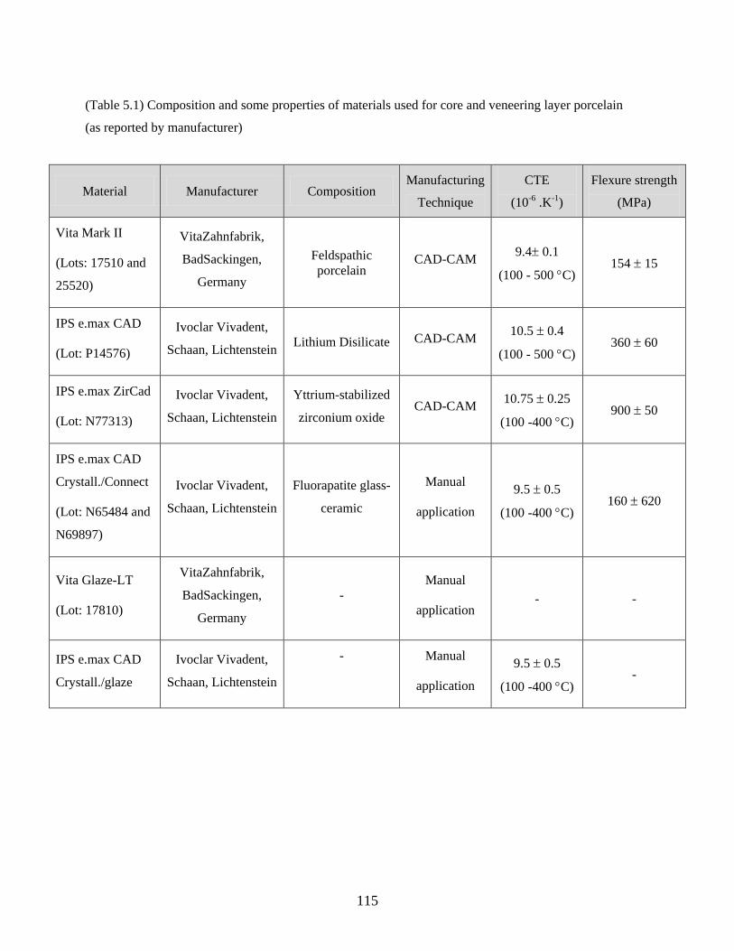
115
(Table 5.1) Composition and some properties of materials used for core and veneering layer porcelain
(as reported by manufacturer)
Material Manufacturer Composition Manufacturing
Technique
CTE
(10-6 .K-1)
Flexure strength
(MPa)
Vita Mark II
(Lots: 17510 and
25520)
VitaZahnfabrik,
BadSackingen,
Germany
Feldspathic
porcelain CAD-CAM
9.4 0.1
(100 - 500 C) 154 15
IPS e.max CAD
(Lot: P14576)
Ivoclar Vivadent,
Schaan, Lichtenstein Lithium Disilicate CAD-CAM
10.5 0.4
(100 - 500 C) 360 60
IPS e.max ZirCad
(Lot: N77313)
Ivoclar Vivadent,
Schaan, Lichtenstein
Yttrium-stabilized
zirconium oxide CAD-CAM
10.75 0.25
(100 -400 C) 900 50
IPS e.max CAD
Crystall./Connect
(Lot: N65484 and
N69897)
Ivoclar Vivadent,
Schaan, Lichtenstein
Fluorapatite glass-
ceramic
Manual
application
9.5 0.5
(100 -400 C) 160 620
Vita Glaze-LT
(Lot: 17810)
VitaZahnfabrik,
BadSackingen,
Germany
-
Manual
application - -
IPS e.max CAD
Crystall./glaze
Ivoclar Vivadent,
Schaan, Lichtenstein
-
Manual
application
9.5 0.5
(100 -400 C) -
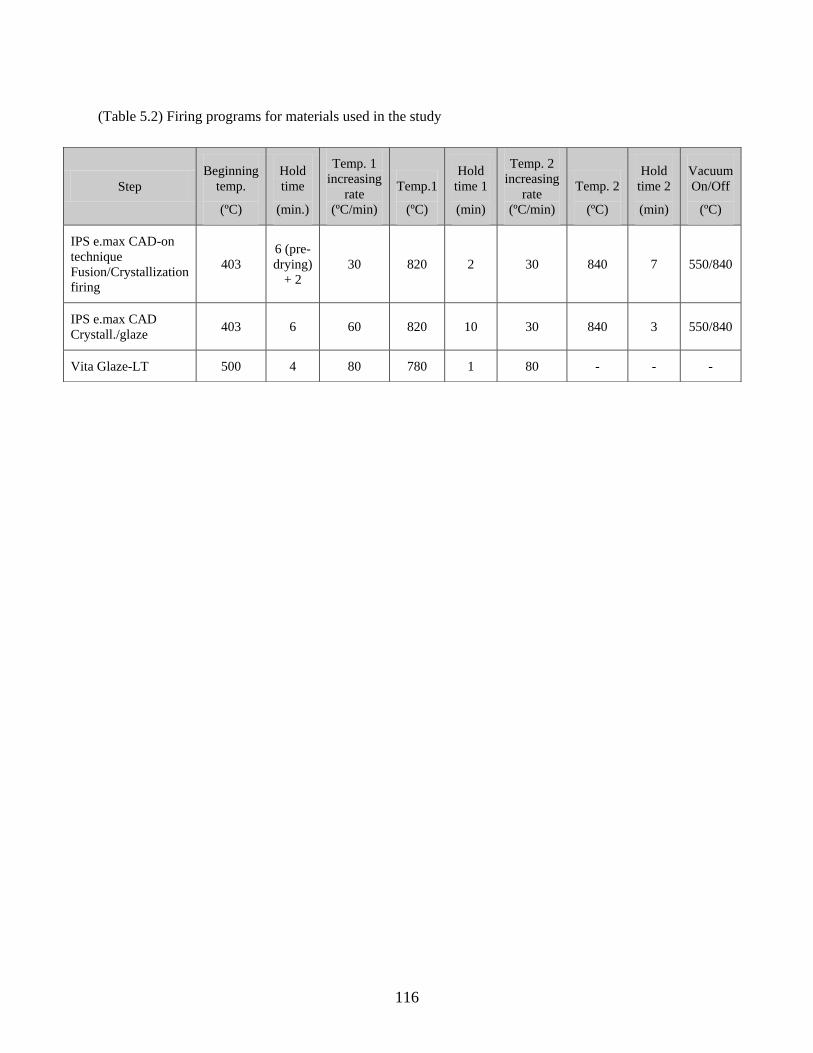
116
(Table 5.2) Firing programs for materials used in the study
Step
Beginning
temp.
(ºC)
Hold
time
(min.)
Temp. 1
increasing
rate
(ºC/min)
Temp.1
(ºC)
Hold
time 1
(min)
Temp. 2
increasing
rate
(ºC/min)
Temp. 2
(ºC)
Hold
time 2
(min)
Vacuum
On/Off
(ºC)
IPS e.max CAD-on
technique
Fusion/Crystallization
firing
403
6 (pre-
drying)
+ 2
30 820 2 30 840 7 550/840
IPS e.max CAD
Crystall./glaze 403 6 60 820 10 30 840 3 550/840
Vita Glaze-LT 500 4 80 780 1 80 - - -
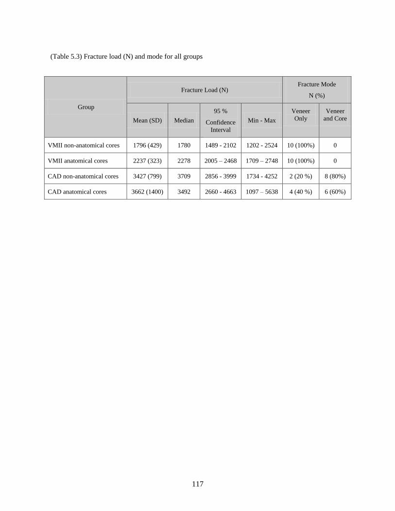
117
(Table 5.3) Fracture load (N) and mode for all groups
Group
Fracture Load (N) Fracture Mode
N (%)
Mean (SD) Median
95 %
Confidence
Interval
Min - Max
Veneer
Only
Veneer
and Core
VMII non-anatomical cores 1796 (429) 1780 1489 - 2102 1202 - 2524 10 (100%) 0
VMII anatomical cores 2237 (323) 2278 2005 – 2468 1709 – 2748 10 (100%) 0
CAD non-anatomical cores 3427 (799) 3709 2856 - 3999 1734 - 4252 2 (20 %) 8 (80%)
CAD anatomical cores 3662 (1400) 3492 2660 - 4663 1097 – 5638 4 (40 %) 6 (60%)
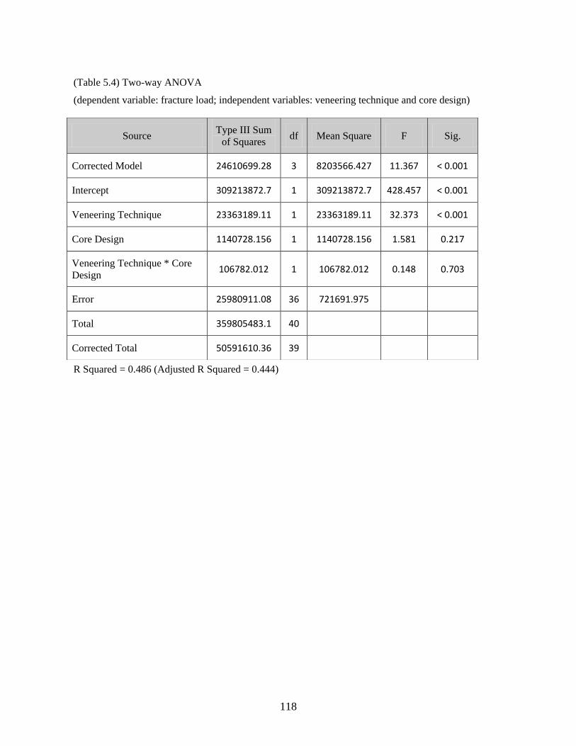
118
(Table 5.4) Two-way ANOVA
(dependent variable: fracture load; independent variables: veneering technique and core design)
R Squared = 0.486 (Adjusted R Squared = 0.444)
Source Type III Sum
of Squares df Mean Square F Sig.
Corrected Model 24610699.28 3 8203566.427 11.367 < 0.001
Intercept 309213872.7 1 309213872.7 428.457 < 0.001
Veneering Technique 23363189.11 1 23363189.11 32.373 < 0.001
Core Design 1140728.156 1 1140728.156 1.581 0.217
Veneering Technique * Core
Design 106782.012 1 106782.012 0.148 0.703
Error 25980911.08 36 721691.975
Total 359805483.1 40
Corrected Total 50591610.36 39
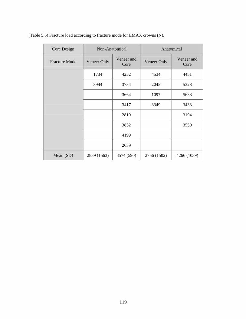
119
(Table 5.5) Fracture load according to fracture mode for EMAX crowns (N).
Core Design Non-Anatomical Anatomical
Fracture Mode Veneer Only Veneer and
Core Veneer Only
Veneer and
Core
1734 4252 4534 4451
3944 3754 2045 5328
3664 1097 5638
3417 3349 3433
2819 3194
3852 3550
4199
2639
Mean (SD) 2839 (1563) 3574 (590) 2756 (1502) 4266 (1039)
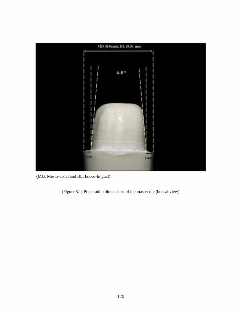
120
(MD: Mesio-distal and BL: bucco-lingual).
(Figure 5.1) Preparation dimensions of the master die (buccal view)
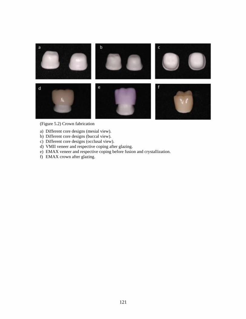
121
(Figure 5.2) Crown fabrication
a) Different core designs (mesial view).
b) Different core designs (buccal view).
c) Different core designs (occlusal view).
d) VMII veneer and respective coping after glazing.
e) EMAX veneer and respective coping before fusion and crystallization.
f) EMAX crown after glazing.
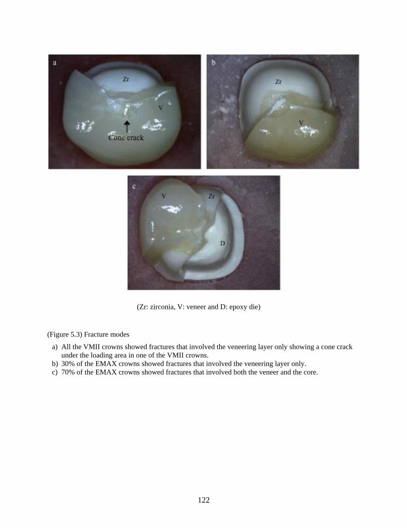
122
(Zr: zirconia, V: veneer and D: epoxy die)
(Figure 5.3) Fracture modes
a) All the VMII crowns showed fractures that involved the veneering layer only showing a cone crack
under the loading area in one of the VMII crowns.
b) 30% of the EMAX crowns showed fractures that involved the veneering layer only.
c) 70% of the EMAX crowns showed fractures that involved both the veneer and the core.
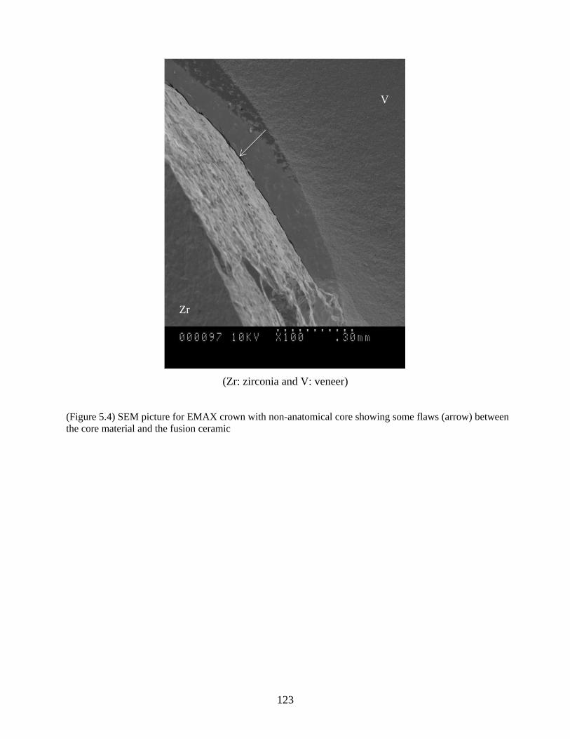
123
(Zr: zirconia and V: veneer)
(Figure 5.4) SEM picture for EMAX crown with non-anatomical core showing some flaws (arrow) between
the core material and the fusion ceramic
V
Zr
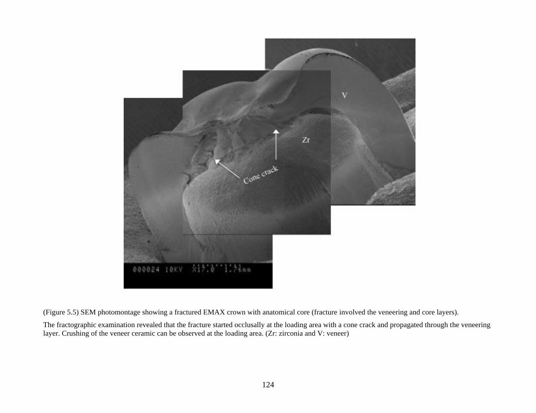
124
(Figure 5.5) SEM photomontage showing a fractured EMAX crown with anatomical core (fracture involved the veneering and core layers).
The fractographic examination revealed that the fracture started occlusally at the loading area with a cone crack and propagated through the veneering
layer. Crushing of the veneer ceramic can be observed at the loading area. (Zr: zirconia and V: veneer)
125
References
1. Goodacre CJ, Bernal G, Rungcharassaeng K, Kan JY. Clinical complications in
fixed prosthodontics. J Prosthet Dent 2003;90(1):31-41.
2. Kelly JR. Dental ceramics: current thinking and trends. Dent Clin North Am
2004;48(2):viii, 513-viii, 30.
3. Anusavice KJ, Phillips RW. Phillips' science of dental materials. 1996;10th:66.
4. Denry I, Kelly JR. State of the art of zirconia for dental applications. Dent Mater
2008;24(3):299-307.
5. Albakry M, Guazzato M, Swain MV. Effect of sandblasting, grinding, polishing
and glazing on the flexural strength of two pressable all-ceramic dental materials.
J Dent 2004;32(2):91-9.
6. Christel P, Meunier A, Heller M, Torre JP, Peille CN. Mechanical properties and
short-term in-vivo evaluation of yttrium-oxide-partially-stabilized zirconia. J
Biomed Mater Res 1989;23(1):45-61.
7. White SN, Miklus VG, McLaren EA, Lang LA, Caputo AA. Flexural strength of
a layered zirconia and porcelain dental all-ceramic system. J Prosthet Dent
2005;94(2):125-31.
8. Raigrodski AJ, Hillstead MB, Meng GK, Chung KH. Survival and complications
of zirconia-based fixed dental prostheses: a systematic review. J Prosthet Dent
2012;107(3):170-7.
9. Cehreli MC, Kokat AM, Akca K. CAD/CAM Zirconia vs. slip-cast glass-
infiltrated Alumina/Zirconia all-ceramic crowns: 2-year results of a randomized
controlled clinical trial. J Appl Oral Sci 2009;17(1):49-55.
10. Heintze SD, Rousson V. Survival of zirconia- and metal-supported fixed dental
prostheses: a systematic review. Int J Prosthodont 2010;23(6):493-502.
11. Ortorp A, Kihl ML, Carlsson GE. A 3-year retrospective and clinical follow-up
study of zirconia single crowns performed in a private practice. J Dent
2009;37(9):731-6.
12. Hosseini M, Worsaae N, Schiodt M, Gotfredsen K. A 1-year randomised
controlled trial comparing zirconia versus metal-ceramic implant supported
single-tooth restorations. Eur J Oral Implantol 2011;4(4):347-61.
13. Rinke S, Schafer S, Roediger M. Complication rate of molar crowns: a practice-
based clinical evaluation. Int J Comput Dent 2011;14(3):203-18.
14. Sagirkaya E, Arikan S, Sadik B, Kara C, Karasoy D, Cehreli M. A randomized,
prospective, open-ended clinical trial of zirconia fixed partial dentures on teeth
and implants: interim results. Int J Prosthodont 2012;25(3):221-31.
15. de Kler M, de Jager N, Meegdes M, van der Zel JM. Influence of thermal
expansion mismatch and fatigue loading on phase changes in porcelain veneered
Y-TZP zirconia discs. J Oral Rehabil 2007;34(11):841-7.
126
16. Swain MV. Unstable cracking (chipping) of veneering porcelain on all-ceramic
dental crowns and fixed partial dentures. Acta Biomater 2009;5(5):1668-77.
17. Tholey MJ, Swain MV, Thiel N. SEM observations of porcelain Y-TZP interface.
Dent Mater 2009;25(7):857-62.
18. Sailer I, Feher A, Filser F, Gauckler LJ, Luthy H, Hammerle CH. Five-year
clinical results of zirconia frameworks for posterior fixed partial dentures. Int J
Prosthodont 2007;20(4):383-8.
19. Raigrodski AJ, Chiche GJ, Potiket N, Hochstedler JL, Mohamed SE, Billiot S, et
al. The efficacy of posterior three-unit zirconium-oxide-based ceramic fixed
partial dental prostheses: a prospective clinical pilot study. J Prosthet Dent
2006;96(4):237-44.
20. Aboushelib MN, de Jager N, Kleverlaan CJ, Feilzer AJ. Microtensile bond
strength of different components of core veneered all-ceramic restorations. Dent
Mater 2005;21(10):984-91.
21. Guess PC, Kulis A, Witkowski S, Wolkewitz M, Zhang Y, Strub JR. Shear bond
strengths between different zirconia cores and veneering ceramics and their
susceptibility to thermocycling. Dent Mater 2008;24(11):1556-67.
22. Marchack BW, Futatsuki Y, Marchack CB, White SN. Customization of milled
zirconia copings for all-ceramic crowns: a clinical report. J Prosthet Dent
2008;99(3):169-73.
23. Aboushelib MN, de Kler M, van der Zel JM, Feilzer AJ. Effect of veneering
method on the fracture and bond strength of bilayered zirconia restorations. Int J
Prosthodont 2008;21(3):237-40.
24. Beuer F, Schweiger J, Eichberger M, Kappert HF, Gernet W, Edelhoff D. High-
strength CAD/CAM-fabricated veneering material sintered to zirconia copings--a
new fabrication mode for all-ceramic restorations. Dent Mater 2009;25(1):121-8.
25. Drummond JL, Eliades G. Ceramic behavior under different environmental and
loading conditions. Dental materials in vivo : aging and related phenomena:
Chicago ; London : Quintessence Pub. Co.; 2003. p. 35-45.
26. Rosenstiel SF, Land MF, Fujimoto J. Contemporary fixed prosthodontics. St.
Louis: Mosby; 2001. p. 643-72.
27. Evans AG. Slow crack growth in brittle materials under dynamic loading
conditions. International Journal of Fracture 1974;10(2):251-59.
28. Evans AG, Johnson H. Fracture stress and its dependence on slow crack growth.
Journal of Materials Science 1975;10(2):214-22.
29. Wiederho SM. Moisture assisted crack growth in ceramics. International Journal
of Fracture Mechanics 1968;4(2):171-77.
30. Choi JE, Waddell JN, Torr B, Swain MV. Pressed ceramics onto zirconia. Part 1:
Comparison of crystalline phases present, adhesion to a zirconia system and
flexural strength. Dent Mater 2011;27(12):1204-12.
127
31. Stawarczyk B, Ozcan M, Roos M, Trottmann A, Sailer I, Hammerle CH. Load-
bearing capacity and failure types of anterior zirconia crowns veneered with
overpressing and layering techniques. Dent Mater 2011;27(10):1045-53.
32. Lee JJ, Wang Y, Lloyd IK, Lawn BR. Joining veneers to ceramic cores and
dentition with adhesive interlayers. J Dent Res 2007;86(8):745-8.
33. Saied MA, Lloyd IK, Haller WK, Lawn BR. Joining dental ceramic layers with
glass. Dent Mater 2011;27(10):1011-6.
34. Guess PC, Bonfante EA, Silva NR, Coelho PG, Thompson VP. Effect of core
design and veneering technique on damage and reliability of Y-TZP-supported
crowns. Dent Mater 2013;29(3):307-16.
35. Kokubo Y, Tsumita M, Kano T, Fukushima S. The influence of zirconia coping
designs on the fracture load of all-ceramic molar crowns. Dent Mater J
2011;30(3):281-5.
36. Larsson C, El Madhoun S, Wennerberg A, Vult von Steyern P. Fracture strength
of yttria-stabilized tetragonal zirconia polycrystals crowns with different design:
an in vitro study. Clin Oral Implants Res 2012;23(7):820-6.
37. Rosentritt M, Steiger D, Behr M, Handel G, Kolbeck C. Influence of substructure
design and spacer settings on the in vitro performance of molar zirconia crowns. J
Dent 2009;37(12):978-83.
38. Sundh A, Sjogren G. A comparison of fracture strength of yttrium-oxide-
partially-stabilized zirconia ceramic crowns with varying core thickness, shapes
and veneer ceramics. J.Oral Rehabil. 2004;31(7):682-88.
39. Molin MK, Karlsson SL. Five-year clinical prospective evaluation of zirconia-
based Denzir 3-unit FPDs. Int J Prosthodont 2008;21(3):223-7.
40. Tinschert J, Schulze KA, Natt G, Latzke P, Heussen N, Spiekermann H. Clinical
behavior of zirconia-based fixed partial dentures made of DC-Zirkon: 3-year
results. Int J Prosthodont 2008;21(3):217-22.
41. Neiva G, Yaman P, Dennison JB, Razzoog ME, Lang BR. Resistance to fracture
of three all-ceramic systems. J Esthet Dent 1998;10(2):60-6.
42. Blatz MB. Cementation of zirconium-oxide ceramic restorations. Pract Proced
Aesthet Dent 2004;16(1):14.
43. Pallis K, Griggs JA, Woody RD, Guillen GE, Miller AW. Fracture resistance of
three all-ceramic restorative systems for posterior applications. J Prosthet Dent
2004;91(6):561-9.
44. Choi JE, Waddell JN, Swain MV. Pressed ceramics onto zirconia. Part 2:
indentation fracture and influence of cooling rate on residual stresses. Dent Mater
2011;27(11):1111-8.
45. Zahran M, El-Mowafy O, Tam L, Watson PA, Finer Y. Fracture Strength and
Fatigue Resistance of All-Ceramic Molar Crowns Manufactured with CAD/CAM
Technology. J Prosthodont 2008.
128
46. Kelly JR. Clinically relevant approach to failure testing of all-ceramic
restorations. J Prosthet Dent 1999;81(6):652-61.
47. Wiskott HW, Nicholls JI, Belser UC. Stress fatigue: basic principles and
prosthodontic implications. Int J Prosthodont. 1995;8(2):105-16.
48. Alhasanyah A, Vaidyanathan TK, Flinton RJ. Effect of Core Thickness
Differences on Post-Fatigue Indentation Fracture Resistance of Veneered
Zirconia Crowns. J Prosthodont 2013.
49. Bhowmick S, Melendez-Martinez JJ, Zhang Y, Lawn BR. Design maps for
failure of all-ceramic layer structures in concentrated cyclic loading. Acta Mater
2007;55(7):2479-88.
50. Mainjot AK, Schajer GS, Vanheusden AJ, Sadoun MJ. Influence of cooling rate
on residual stress profile in veneering ceramic: measurement by hole-drilling.
Dent Mater 2011;27(9):906-14.
51. Hermann I, Bhowmick S, Lawn BR. Role of core support material in veneer
failure of brittle layer structures. J Biomed Mater Res B Appl Biomater
2007;82(1):115-21.
52. Kelly JR, Hunter BD, Brenyo MR, Peterson IM. Simulating clinical failure
during in vitro testing of all-ceramic crowns. J Dent Res 1998;77:778.
53. Lawn BR. Fracture of brittle solids. Cambridge solid state science series. 2nd ed.
Cambridge ; New York: Cambridge University Press; 1993. p. 249-306.
129
Chapter 6: Manuscript 4
130
Characterization of the interface between zirconia and veneering porcelain
Authors:
Mohammed H. Zahran, BDS, MSc, PhD-candidate
Department of Prosthodontics, Faculty of Dentistry, University of Toronto, Toronto, ON, Canada
Department of Fixed Prosthodontics, Faculty of Dentistry, King Abdulaziz University, Jeddah,
Saudi Arabia
*Omar El-Mowafy, BDS, PhD, FADM
Professor and Head, Department of Restorative Dentistry, Faculty of Dentistry, University of Toronto,
Toronto, ON, Canada
Asbjorn Jokstad, DDS, PhD
Professor and Head, Department of Prosthodontics, Faculty of Dentistry, University of Toronto,
Toronto, ON, Canada
University of Tromso, Norway
Laura E.Tam, DDS, MSc
Professor, Department of Restorative Dentistry, Faculty of Dentistry, University of Toronto, Toronto,
ON, Canada
Amin S. Rizkalla, P Eng, PhD
Associate Professor and Head, Department of Biomaterials Science, Schulich School of Medicine &
Dentistry, The University of Western Ontario, London, ON, Canada
*Corresponding author
Omar El-Mowafy, BDS, PhD, FADM
Department of Clinical Sciences
Faculty of Dentistry, University of Toronto
124 Edward Street, Toronto, Ontario M5G 1G6, Canada.
Phone: (416) 979-4934 X 4572
Fax: (416) 979-4936
E-mail: [email protected]
This work was previously presented in part at the 39th General Session & Exhibition of the AADR,
Washington, DC, USA in 2010
131
Abstract
Objective: To evaluate the interface between the zirconium oxide core and veneering
porcelain using Time of Flight Secondary Ion Mass Spectrometry (ToF-SIMS) and X-ray
Photoelectron Spectroscopy (XPS). Methods: Four zirconium oxide slices (IPS e.max
ZirCad) were sintered to make rectangular specimens (1mm in thickness). A liner
material (IPS e.max Zirliner) was applied to two of the zirconia squares followed by
pressed (IPS e.max ZirPress) or manually applied (IPS e.max Ceram, Ivoclar Vivadent)
veneering porcelain. The other two squares were veneered as above but without the liner
material. The specimens were cross-sectioned using diamond discs on Leica TXP,
targeted sectioning and polishing unit (Leica Microsystems Inc). Before the surface
analysis, the samples were pre-cleaned with a 1 keV Ar+ ion beam. The chemical
composition changes along the interfacial areas of all the specimens (N=4) were
examined using Time of Flight Secondary Ion Mass Spectrometry (ToF-SIMS)
complemented by X-ray Photoelectron Spectroscopy (XPS). Results: Oxygen was the
main element present on both the veneer and core area. Sodium, silicon and aluminum
were the dominant elements in the veneering porcelain, while zirconium was the
dominant element in the zirconia core. XPS analyses revealed total disappearance of the
aluminum and sodium at the core region. A significant decrease (but not total
disappearance) in the relative atomic percentage of zirconium in the veneering porcelain
region was detected compared to the core region. ToF-SIMS data revealed variations in
zirconium chemistry in the interfacial region. Conclusions: The result of this study is
indicative of chemical changes of the zirconium along the interface regardless of the
veneering porcelain application technique or the usage of the liner. Further investigations
are needed to confirm and explain these changes.
132
Introduction
Several short-term clinical studies reported a high incidence of veneering porcelain
chipping.1-7
This high chipping rate, in comparison to that of metal-ceramic restorations,
led manufacturers and clinicians to seek explanations. Several hypothetical explanations
have been reported, including: occlusal overloading, residual stresses as a result of the
mismatch in the coefficient of thermal expansion (CTE) between core and veneering
porcelain, 8, 9
residual “tempering” stresses due to the thermal gradient between the
veneering porcelain and the zirconia core,9 interfacial stresses as a result of crystal
transformation at the interface,10
inadequate framework support,11
inherent strength
deficiency of the veneering porcelain 11, 12
and a weak porcelain-zirconia bond.13, 14
Several studies have focused on measuring the zirconia-veneering porcelain bond
strength and comparing it to that of the metal-veneering porcelain.14-19
Other studies
focused on the effect of different factors on the zirconia-veneer bonding strength,
including: core-veneer CTE mismatch, use of the liner,20-22
surface treatment of the
core,21-27
veneering porcelain cooling rate28, 29
and veneering porcelain application
method and composition. 18, 25, 30-34
Unfortunately, little attention was directed to the
mechanism of the bonding between zirconia core and the veneering porcelain. It is not
clear whether the bond between the two materials is mechanical or a combination of both
chemical and mechanical. A recent study reported that zirconia and alumina as core
materials demonstrated mechanical bonding with silicate porcelain veneers, whereas
glass infiltrated alumina and lithium disilicate glass ceramic have reactive chemical
bonding towards silicate veneers. 35
The chemical structure at the core-veneer interface
was analyzed using Energy Dispersive X-ray (EDX), which revealed that some of the
veneer elements diffused into the zirconium oxide layer to a depth of 8 -10 μm.20
The objective of this study was to evaluate the nature of the bond between the
zirconium oxide core and matching veneering porcelain using the Time of Flight
Secondary Ion Mass Spectrometry (ToF-SIMS) and X-ray Photoelectron Spectroscopy
(XPS).
133
Materials and Methods:
Specimen preparation
Four zirconia rectangular specimens (11.5 x 12.5 x 1 mm) were prepared. These were
sliced from IPS e.max ZirCAD CEREC blocks (Size B40) (Ivoclar Vivadent, Schaan,
Lichtenstein) with a slow-speed diamond saw (Isomet, Buehler, Lake Buff, IL, USA).
The thickness of the slices was increased by 25% before cutting to compensate for the
shrinkage of zirconia that takes place during sintering. All slices were sintered in a high-
temperature furnace (Sintramat, Ivoclar Vivadent) according to manufacturer’s
instructions at a temperature of 1530◦C. The duration of the program, including the
cooling phase, was approximately 8 hours.
After sintering, a layer of ceramic bond (IPS e.max Zirliner, Ivoclar Vivadent)
was applied to one of the surfaces of two of the zirconia specimens, while the other two
samples were left without liner application. The Zirliner powder was mixed with build-
up liquid (Ivoclar Vivadent) to a creamy consistency, then layered onto the core
specimens, vibrated to achieve an even, greenish color, and finally fired in a porcelain
furnace (Whip Mix Pro 100, Whip Mix Corp, Louisville, KY, USA) according to the
manufacturer’s instructions (Table 6.1).
The zirconia specimens were then veneered with one of two veneering porcelains,
manually-applied or pressed, to produce four samples as follows: zirconia/manually-
applied veneer with liner (sample 1), zirconia/ manually-applied veneer without liner
(sample 2), zirconia/pressed veneer with liner (sample 3) and zirconia/pressed veneer
without liner (sample 4). The powder of the manually applied veneering material (IPS
e.max Ceram, Ivoclar Vivadent) was mixed with the manufacturer’s recommended liquid.
The obtained slurry was vibrated and condensed into the mold and the excess liquid was
removed by means of absorbent paper. The mold was removed and the specimens were
fired in a porcelain furnace (Whip Mix Pro 100) according to the manufacturer’s
instructions (Table 6.1). For the pressed veneer specimens, a wax pattern was applied on
the zirconia discs. The wax patterns were sprued and invested using a phosphate-bonded
investment material (IPS PressVEST Speed, Ivoclar Vivadent). The ceramic ingot (IPS
e.max Zirpress, Ivoclar Vivadent) was pressed according to the manufacturer’s
134
instructions using a pressing furnace (EP600 Combi, Ivoclar Vivadent) (Table 6.1). The
samples were sectioned perpendicular to the interface using a diamond saw (Leica TXP,
Leica Microsystems GmbH, Vienna, Austria).
ToF-SIMS analysis
Each sample was analyzed using ToF-SIMS IV, (IONTOF GMBH., Munster,
Germany). The area chosen for analysis was initial 191 x 191 μm2
straddling the
interfacial area for sample 1 and 500 x 500 μm2
for the other samples. First, The
analysis area was cleaned using a high current (90 nA, 3 keV) Ar+ ion beam for several
minutes until the main surface signal stabilized, indicating that the surface
contaminants had been reduced to steady state levels. A Bi+ ions (1.0 pA, 25 keV)
beam was used to generate the spectra in both high spatial and high spectral resolution
modes.36
Charge neutralization was achieved by using low-energy electron flooding.
Both positive and negative spectra were acquired and analyzed using
IonSpec/IonImage software (IONTOF GMBH). The collected spectra were used to
produce different ToF-SIMS pictures for the distribution of different ions in the
analysis area.
Samples of the liner and manually-applied veneering porcelain powders were also
separately analyzed to get their baseline spectra. Baseline spectra for the pressed
veneering porcelain and zirconia core material were not collected due to technical
difficulties.
• XPS analysis
As for the ToF-SIMS, the analysis area was sputter-cleaned with a 3keV Ar+ ion
beam. All XPS measurements were obtained with a Thermo Scientific K-Alpha X-ray
Photoelectron Spectrometer (East Grinstead, UK), with monochromated Al K-alpha X-
rays. Data were acquired across the interface using 30 μm spot size. Charge
compensation was performed using a low-energy flood. Vacuum pressure was 10-7
mbar,
with the vast majority of residual pressure from Argon associated with operation of the
135
charge compensation source. The spectra that were used for determining elemental
compositions were acquired in high pass energy snapshot mode. XPS data was analyzed
with Avantage software (East Grinstead, UK). Surface elemental compositions were
calculated from background-subtracted peak areas derived from transmission function
corrected regional spectra. Sensitivity factors (Scofield), which were provided by the
manufacturer, were used to calculate the relative atomic percentages.
136
Results and Discussion:
The chemical compositions of the different materials used in this study as provided
by the manufacturer are summarized in Table 6.2.
ToF-SIMS images for the 4 samples are presented in Figures 6.1 to 6.4 (brighter
areas indicate greater signals than the darker ones). The layers of the sample (core,
veneer and liner (if applied) can be clearly differentiated in these images. In agreement
with the chemical composition provided by the manufacturer, sodium, silicon and
aluminum were the dominant elements appearing in the liner and veneer layers, while
zirconium was the dominant element in the zirconia core. An interesting finding is the
appearance of zirconium across the interface although that the ToF-SIMS baseline
spectra of the liner and veneering porcelain did not show any presence of zirconium
(Figure 6.5). It is difficult to make a conclusion about the source of the zirconium across
the interface and in the veneering layer. Plausible explanations are the diffusion of the
zirconium from the core or a contamination from the diamond saw during sectioning.
The presence of the zirconium along the interface was confirmed and quantified using
the XPS technique. XPS data showed a significant decrease (but not total disappearance)
in the relative atomic percentage of zirconium at the interface region. In contrast,
elements like silicon, which is one of the main constituents of the veneering material,
disappeared completely at the interface region. XPS data for the changes in the relative
atomic percentage across the interface for all the 4 samples can be seen in Figures 6.6 to
6.9.
Furthermore, ToF SIMS data revealed a change in the zirconium chemistry away
from and near to the interface (Figure 6.10). The fragmentation patterns of the Zr (around
90 mass/units) and ZrxOy (around 105 mass/units) peaks are inherently related to the
chemistry of the system. Taking spectra from pixels in the region near the interfacial
boundary and comparing them to spectra taken away from this boundary reflected
differences in the chemistry of zirconium. This difference in the relative intensities of the
Zr/ZrH and ZrO/ZrOH signals is reflective of a real change in the zirconia chemistry.
As stated in the introduction, the chemical changes at the core-veneer interface was
analyzed in a previous study using Energy Dispersive X-ray (EDX), which revealed that
137
some of the veneer elements diffused into the zirconium oxide layer to a depth of 8 -10
μm.20
Although It is very difficult to confirm this observation in the current study due to
the difficulty of locating an exact point representing the interface, it has to be emphasized
that elements in the veneering and liner layers disappeared at different distances across
the interfacial region. XPS data showed that element like the sodium and aluminum
disappeared first followed by silicon.
While looking at the interface in cross-section is one of the approaches to study the
zirconia-veneer interface, this approach is limited depth-wise by the spatial resolution of
the ToF-SIMS (about 70 nm) and the XPS (about 10 μm). An alternative approach will
be to prepare samples with very thin veneering porcelain (about 10 nm) and look at the
interface through the veneering layer. Unfortunately, preparing such a sample is not
practical. Another approach would be to look at both sides of the fractured samples that
were fractured adhesively through the interface. This approach may eliminate the
possibility of contaminating the surfaces during sectioning and provide some insights
about the interface.
138
Conclusions:
ToF-SIMS and XPS examinations showed the qualitative and quantitative chemical
changes at the interfacial region. An important finding is the presence of zirconium atom
across the interfacial region, although that the chemical composition of both the
veneering and liner powders did not reveal any percentage of the zirconium atoms in
their composition. These changes might be indicative of chemical bonding between the
core and the veneer.
139
Acknowledgements:
This study is part of a PhD thesis submitted to the Faculty of Dentistry, University of
Toronto.
The work was supported by grants from the Faculty of Dentistry Research Committee,
University of Toronto. Special thanks go to Mr. Peter Brodersen from Surface Interface Ontario
for his effort in performing the interfacial analysis.
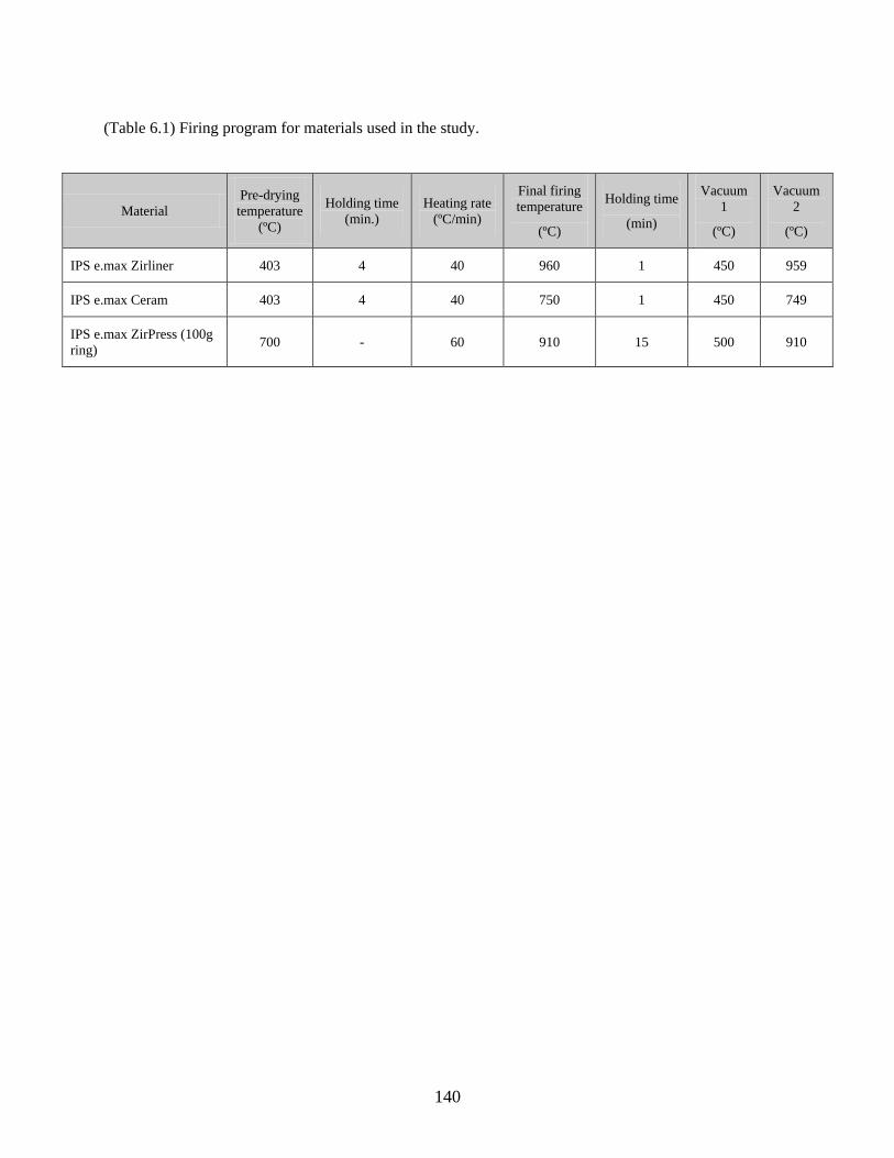
140
(Table 6.1) Firing program for materials used in the study.
Material
Pre-drying
temperature
(ºC)
Holding time
(min.)
Heating rate
(ºC/min)
Final firing
temperature
(ºC)
Holding time
(min)
Vacuum
1
(ºC)
Vacuum
2
(ºC)
IPS e.max Zirliner 403 4 40 960 1 450 959
IPS e.max Ceram 403 4 40 750 1 450 749
IPS e.max ZirPress (100g
ring) 700 - 60 910 15 500 910
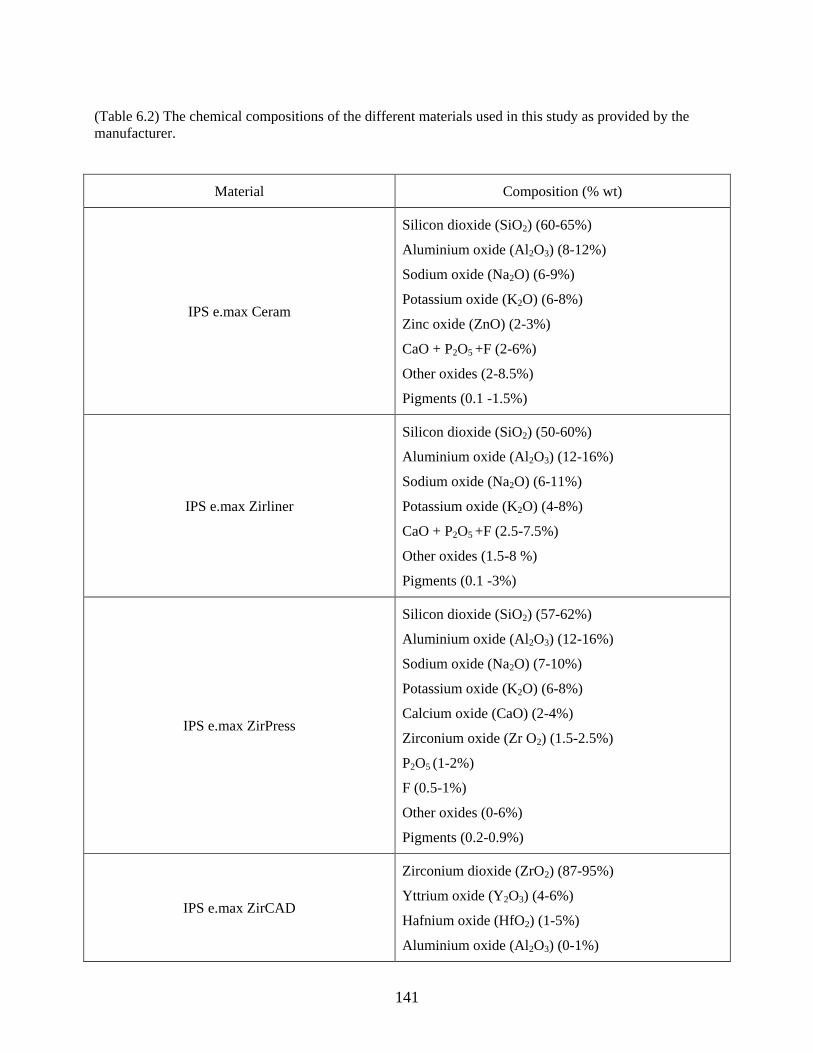
141
(Table 6.2) The chemical compositions of the different materials used in this study as provided by the
manufacturer.
Material Composition (% wt)
IPS e.max Ceram
Silicon dioxide (SiO2) (60-65%)
Aluminium oxide (Al2O3) (8-12%)
Sodium oxide (Na2O) (6-9%)
Potassium oxide (K2O) (6-8%)
Zinc oxide (ZnO) (2-3%)
CaO + P2O5 +F (2-6%)
Other oxides (2-8.5%)
Pigments (0.1 -1.5%)
IPS e.max Zirliner
Silicon dioxide (SiO2) (50-60%)
Aluminium oxide (Al2O3) (12-16%)
Sodium oxide (Na2O) (6-11%)
Potassium oxide (K2O) (4-8%)
CaO + P2O5 +F (2.5-7.5%)
Other oxides (1.5-8 %)
Pigments (0.1 -3%)
IPS e.max ZirPress
Silicon dioxide (SiO2) (57-62%)
Aluminium oxide (Al2O3) (12-16%)
Sodium oxide (Na2O) (7-10%)
Potassium oxide (K2O) (6-8%)
Calcium oxide (CaO) (2-4%)
Zirconium oxide (Zr O2) (1.5-2.5%)
P2O5 (1-2%)
F (0.5-1%)
Other oxides (0-6%)
Pigments (0.2-0.9%)
IPS e.max ZirCAD
Zirconium dioxide (ZrO2) (87-95%)
Yttrium oxide (Y2O3) (4-6%)
Hafnium oxide (HfO2) (1-5%)
Aluminium oxide (Al2O3) (0-1%)
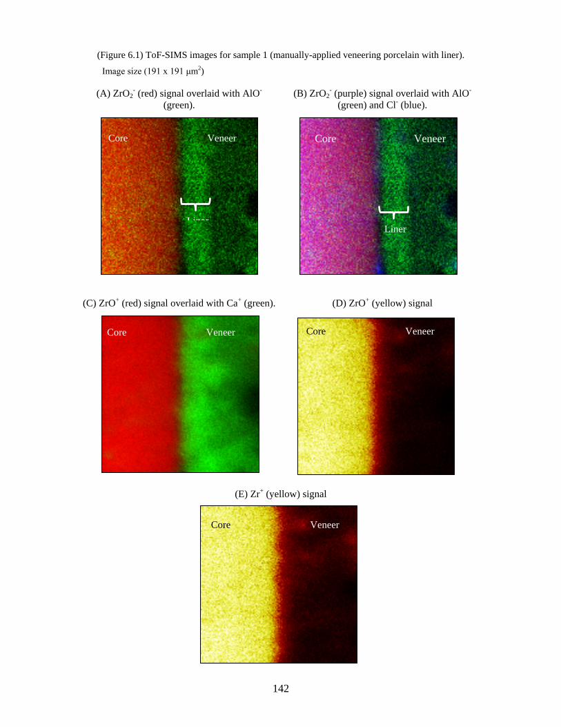
142
(Figure 6.1) ToF-SIMS images for sample 1 (manually-applied veneering porcelain with liner).
Image size (191 x 191 μm2)
(A) ZrO2- (red) signal overlaid with AlO-
(green).
(B) ZrO2- (purple) signal overlaid with AlO-
(green) and Cl- (blue).
(C) ZrO+ (red) signal overlaid with Ca+ (green). (D) ZrO+ (yellow) signal
(E) Zr+ (yellow) signal
Liner
Core Veneer
Liner
Core Veneer
Core Veneer
Core Veneer
Core Veneer
143
(Figure 6.2) Tof SIMS image for sample 2 (manually-applied veneering porcelain without liner)
Image size (500 x 500 μm2)
Zr- (green) signal overlaid with Li- (red).
Core Veneer
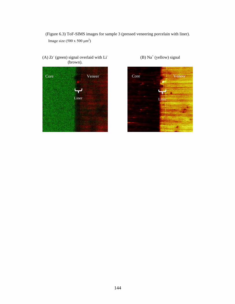
144
(Figure 6.3) ToF-SIMS images for sample 3 (pressed veneering porcelain with liner).
Image size (500 x 500 μm2)
(A) Zr- (green) signal overlaid with Li-
(brown).
(B) Na+ (yellow) signal
Core Veneer
Liner Liner
Core Veneer
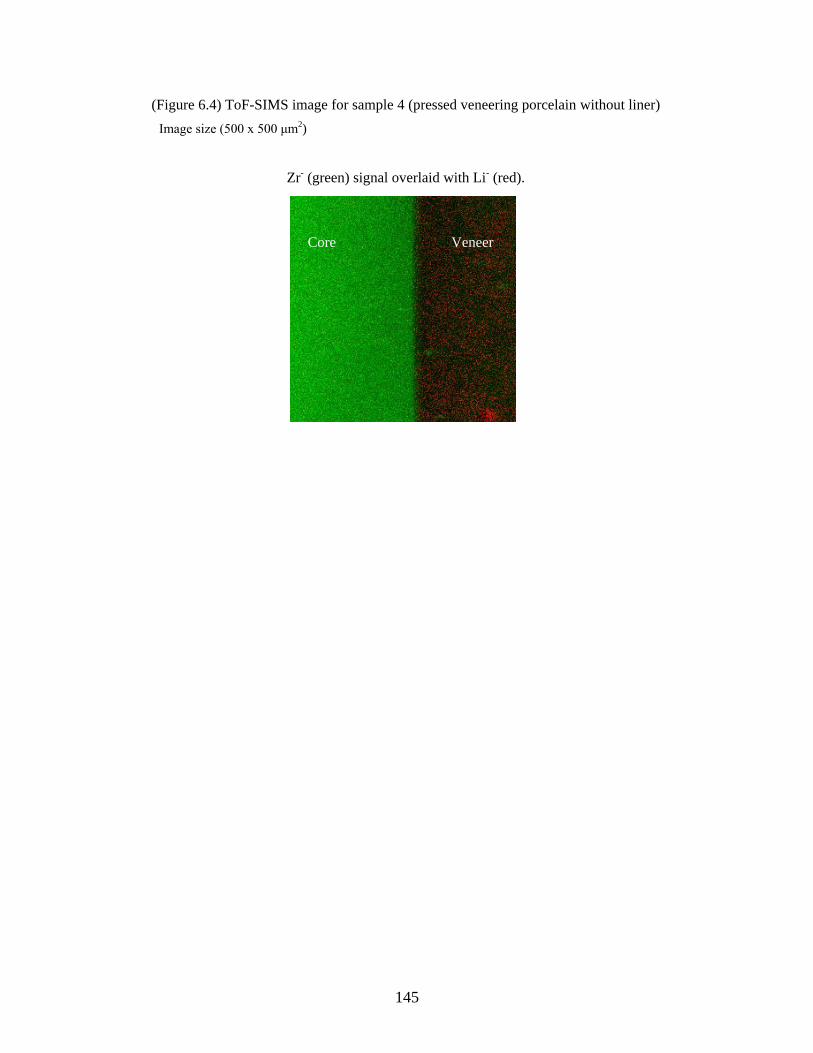
145
(Figure 6.4) ToF-SIMS image for sample 4 (pressed veneering porcelain without liner)
Image size (500 x 500 μm2)
Zr- (green) signal overlaid with Li- (red).
Core Veneer
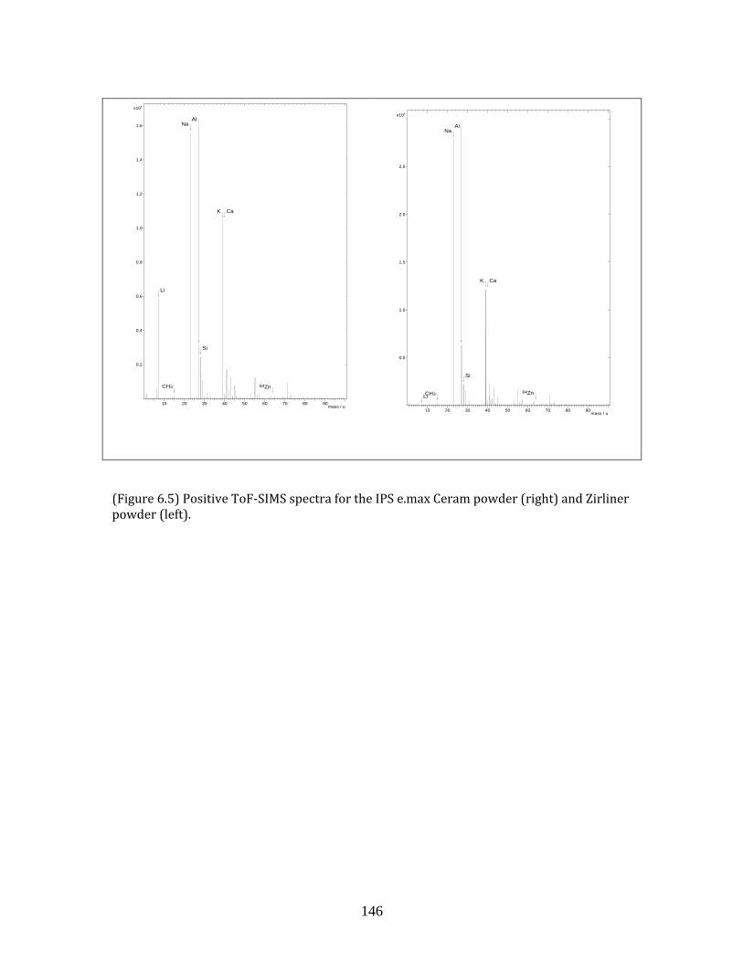
146
(Figure 6.5) Positive ToF-SIMS spectra for the IPS e.max Ceram powder (right) and Zirliner powder (left).
LiCH3
NaAl
Si
K Ca
64Zn
mass / u10 20 30 40 50 60 70 80 90
5x10
0.5
1.0
1.5
2.0
2.5
Inte
nsity
Li
CH3
NaAl
Si
K Ca
64Zn
mass / u10 20 30 40 50 60 70 80 90
5x10
0.2
0.4
0.6
0.8
1.0
1.2
1.4
1.6
Inte
nsity
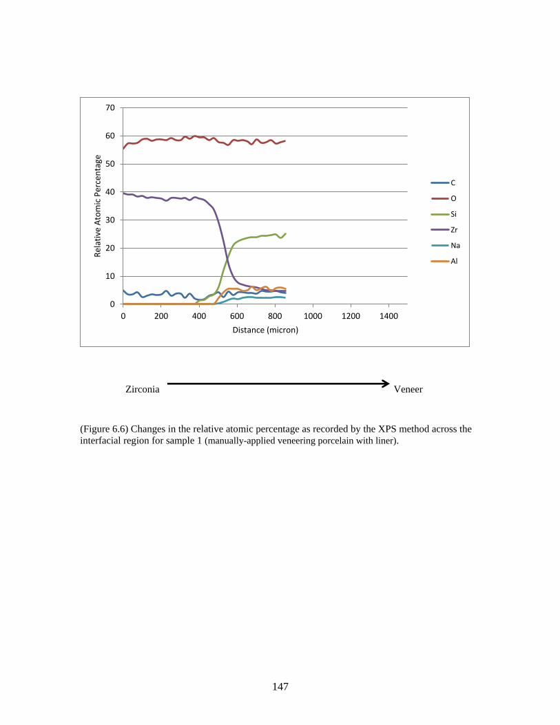
147
Zirconia Veneer
(Figure 6.6) Changes in the relative atomic percentage as recorded by the XPS method across the
interfacial region for sample 1 (manually-applied veneering porcelain with liner).
0
10
20
30
40
50
60
70
0 200 400 600 800 1000 1200 1400
Rel
ativ
e A
tom
ic P
erce
nta
ge
Distance (micron)
C
O
Si
Zr
Na
Al
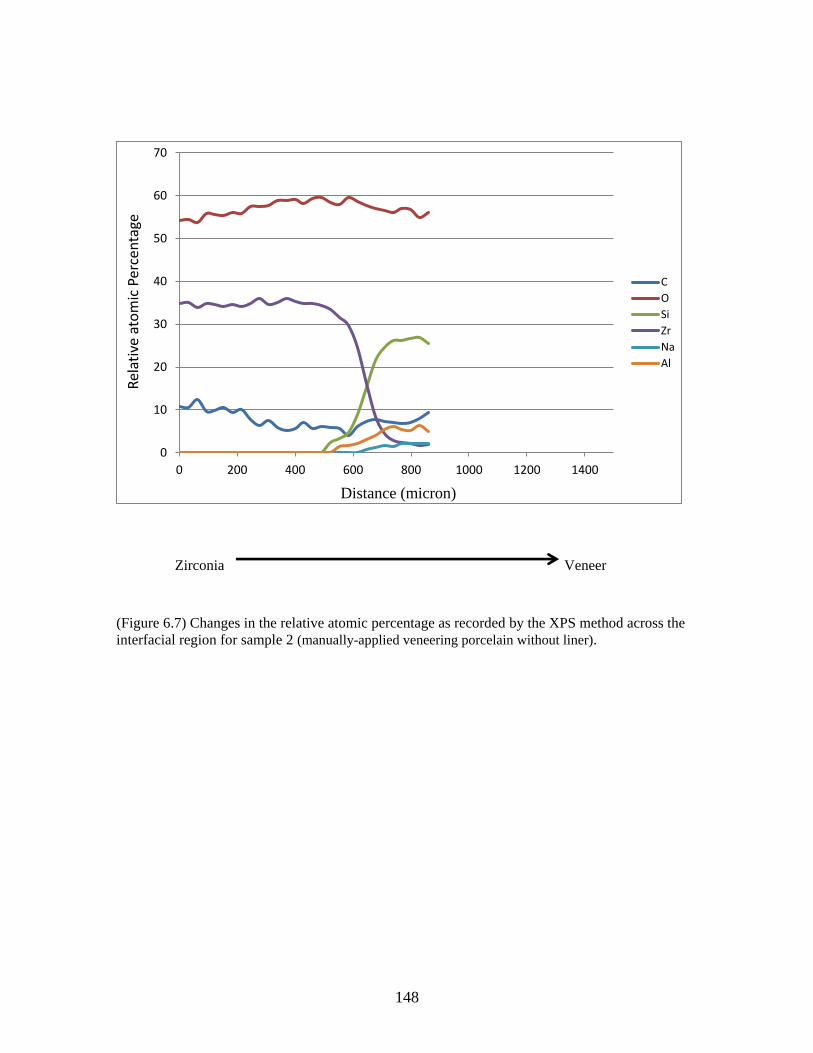
148
Zirconia Veneer
(Figure 6.7) Changes in the relative atomic percentage as recorded by the XPS method across the
interfacial region for sample 2 (manually-applied veneering porcelain without liner).
0
10
20
30
40
50
60
70
0 200 400 600 800 1000 1200 1400
Rel
ativ
e at
om
ic P
erce
nta
ge
Distance (micron)
C
O
Si
Zr
Na
Al
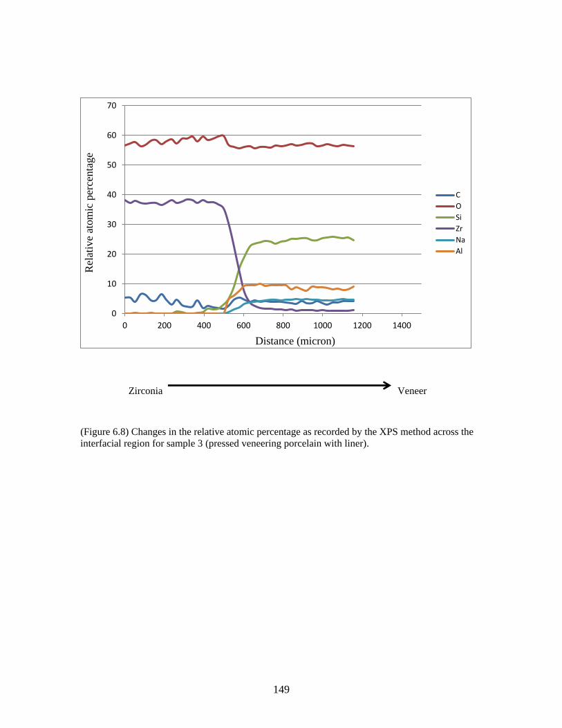
149
Zirconia Veneer
(Figure 6.8) Changes in the relative atomic percentage as recorded by the XPS method across the
interfacial region for sample 3 (pressed veneering porcelain with liner).
0
10
20
30
40
50
60
70
0 200 400 600 800 1000 1200 1400
Rel
ativ
e at
om
ic p
erce
nta
ge
Distance (micron)
C
O
Si
Zr
Na
Al
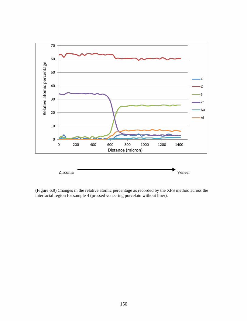
150
Zirconia Veneer
(Figure 6.9) Changes in the relative atomic percentage as recorded by the XPS method across the
interfacial region for sample 4 (pressed veneering porcelain without liner).
0
10
20
30
40
50
60
70
0 200 400 600 800 1000 1200 1400
Rel
ativ
e at
om
ic p
erce
nta
ge
Distance (micron)
C
O
Si
Zr
Na
Al
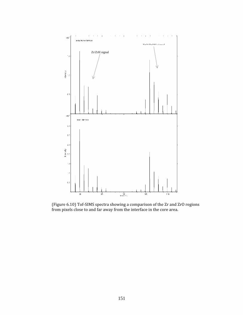
151
(Figure 6.10) Tof-SIMS spectra showing a comparison of the Zr and ZrO regions from pixels close to and far away from the interface in the core area.
Zr/ZrH signal
ZrO/ZrOH signal
152
References
1. Raigrodski AJ, Hillstead MB, Meng GK, Chung KH. Survival and complications of zirconia-based fixed dental prostheses: a systematic review. J Prosthet Dent 2012;107(3):170-7.
2. Cehreli MC, Kokat AM, Akca K. CAD/CAM Zirconia vs. slip-cast glass-infiltrated Alumina/Zirconia all-ceramic crowns: 2-year results of a randomized controlled clinical trial. J Appl Oral Sci 2009;17(1):49-55.
3. Heintze SD, Rousson V. Survival of zirconia- and metal-supported fixed dental prostheses: a systematic review. Int J Prosthodont 2010;23(6):493-502.
4. Ortorp A, Kihl ML, Carlsson GE. A 3-year retrospective and clinical follow-up study of zirconia single crowns performed in a private practice. J Dent 2009;37(9):731-6.
5. Hosseini M, Worsaae N, Schiodt M, Gotfredsen K. A 1-year randomised controlled trial comparing zirconia versus metal-ceramic implant supported single-tooth restorations. Eur J Oral Implantol 2011;4(4):347-61.
6. Rinke S, Schafer S, Roediger M. Complication rate of molar crowns: a practice-based clinical evaluation. Int J Comput Dent 2011;14(3):203-18.
7. Sagirkaya E, Arikan S, Sadik B, Kara C, Karasoy D, Cehreli M. A randomized, prospective, open-ended clinical trial of zirconia fixed partial dentures on teeth and implants: interim results. Int J Prosthodont 2012;25(3):221-31.
8. de Kler M, de Jager N, Meegdes M, van der Zel JM. Influence of thermal expansion mismatch and fatigue loading on phase changes in porcelain veneered Y-TZP zirconia discs. J Oral Rehabil 2007;34(11):841-7.
9. Swain MV. Unstable cracking (chipping) of veneering porcelain on all-ceramic dental crowns and fixed partial dentures. Acta Biomater 2009;5(5):1668-77.
10. Tholey MJ, Swain MV, Thiel N. SEM observations of porcelain Y-TZP interface. Dent Mater 2009;25(7):857-62.
11. Sailer I, Feher A, Filser F, Gauckler LJ, Luthy H, Hammerle CH. Five-year clinical results of zirconia frameworks for posterior fixed partial dentures. Int J Prosthodont 2007;20(4):383-8.
12. Raigrodski AJ, Chiche GJ, Potiket N, Hochstedler JL, Mohamed SE, Billiot S, et al. The efficacy of posterior three-unit zirconium-oxide-based ceramic fixed partial dental prostheses: a prospective clinical pilot study. J Prosthet Dent 2006;96(4):237-44.
13. Aboushelib MN, de Jager N, Kleverlaan CJ, Feilzer AJ. Microtensile bond strength of different components of core veneered all-ceramic restorations. Dent Mater 2005;21(10):984-91.
153
14. Guess PC, Kulis A, Witkowski S, Wolkewitz M, Zhang Y, Strub JR. Shear bond strengths between different zirconia cores and veneering ceramics and their susceptibility to thermocycling. Dent Mater 2008;24(11):1556-67.
15. Al-Dohan HM, Yaman P, Dennison JB, Razzoog ME, Lang BR. Shear strength of core-veneer interface in bi-layered ceramics. J Prosthet Dent 2004;91(4):349-55.
16. Saito A, Komine F, Blatz MB, Matsumura H. A comparison of bond strength of layered veneering porcelains to zirconia and metal. J Prosthet Dent 2010;104(4):247-57.
17. Choi B-K, Han J-S, Yang J-H, Lee J-B, Kim S-H. Shear bond strength of veneering porcelain to zirconia and metal cores. The Journal of Advanced Prosthodontics 2009;1(3):129.
18. Lopez-Molla MV, Martinez-Gonzalez MA, Manes-Ferrer JF, Amigo-Borras V, Bouazza-Juanes K. Bond strength evaluation of the veneering-ceramics bonds. Medicina Oral Patología Oral y Cirugia Bucal 2010:e919-e23.
19. Blatz MB, Bergler M, Ozer F, Holst S, Phark JH, Chiche GJ. Bond strength of different veneering ceramics to zirconia and their susceptibility to thermocycling. Am J Dent 2010;23(4):213-6.
20. Aboushelib MN, Kleverlaan CJ, Feilzer AJ. Microtensile bond strength of different components of core veneered all-ceramic restorations. Part II: Zirconia veneering ceramics. Dent Mater 2006;22(9):857-63.
21. Aboushelib MN, Kleverlaan CJ, Feilzer AJ. Effect of zirconia type on its bond strength with different veneer ceramics. J Prosthodont 2008;17(5):401-8.
22. Mosharraf R, Rismanchian M, Savabi O, Ashtiani AH. Influence of surface modification techniques on shear bond strength between different zirconia cores and veneering ceramics. The Journal of Advanced Prosthodontics 2011;3(4):221.
23. Evil D, Ozden N, Celik E. Surface Roughness Effect on the Bonding of Y-Tzp Ceramics. J Dent Res 2008;87 (Spec Iss B): Abstract 2307.
24. Hill TJ, Tysowsky G. Effect of Sandblasting on Bond Strength of Three Zirconia Porcelains, . J Dent Res 2007;86 (Spec Iss A): Abstract 2448.
25. Kunii J, Kuriyama S, Hotta Y, Goldammer C, Tamaki Y, Fujishima A, et al. Effect of Porcelain Composition and Surface Treatments to Zirconia Bonding. J Dent Res 2009;88, (Spec Iss A): Abstract 1865.
26. Queiroz JR, Benetti P, Massi M, Junior LN, Della Bona A. Effect of multiple firing and silica deposition on the zirconia-porcelain interfacial bond strength. Dent Mater 2012;28(7):763-8.
27. Teng J, Wang H, Liao Y, Liang X. Evaluation of a conditioning method to improve core-veneer bond strength of zirconia restorations. J Prosthet Dent 2012;107(6):380-7.
154
28. Komine F, Saito A, Kobayashi K, Koizuka M, Koizumi H, Matsumura H. Effect of cooling rate on shear bond strength of veneering porcelain to a zirconia ceramic material. J Oral Sci 2010;52(4):647-52.
29. Göstemeyer G, Jendras M, Dittmer MP, Bach F-W, Stiesch M, Kohorst P. Influence of cooling rate on zirconia/veneer interfacial adhesion. Acta Biomaterialia 2010;6(12):4532-38.
30. Aboushelib MN, Kleverlaan CJ, Feilzer AJ. Microtensile bond strength of different components of core veneered all-ceramic restorations. Part 3: double veneer technique. J Prosthodont 2008;17(1):9-13.
31. Gelman A, Belgler M, Saleh N, Atlas AM, Blatz MB. Comparative Bond strength of a Pressed Veneering Ceramic to Zirconia. J Dent Res 2009;88 (Spec Iss A): Abstract 1869.
32. Ishibe M, Raigrodski AJ, Flinn BD, Chung KH, Spiekerman C, Winter RR. Shear bond strengths of pressed and layered veneering ceramics to high-noble alloy and zirconia cores. J Prosthet Dent 2011;106(1):29-37.
33. Aboushelib MN, de Kler M, van der Zel JM, Feilzer AJ. Effect of veneering method on the fracture and bond strength of bilayered zirconia restorations. Int J Prosthodont 2008;21(3):237-40.
34. Choi JE, Waddell JN, Torr B, Swain MV. Pressed ceramics onto zirconia. Part 1: Comparison of crystalline phases present, adhesion to a zirconia system and flexural strength. Dent Mater 2011;27(12):1204-12.
35. Y. Liu, Z. Shen, H. Feng. Chemical Mismatch of Bilayered All-ceramic Dental Composites. J Dent Res 2009;88, (Spec Iss A): Abstract 1862.
36. Sodhi RNS. Time-of-flight secondary ion mass spectrometry (TOF-SIMS): versatility in chemical and imaging surface analysis. Analyst 2004;129(6):483-7.
155
Chapter 7: Summary, Clinical Relevance and
Limitations
156
This thesis aimed to analyze the relatively high chipping rate of the veneering
porcelain of zirconia-based molar crowns; and to study some of the factors that may
affect it in-vitro. This type of crown failure may arise due to weakness of the veneering
porcelain or a weak bond between the core and veneer. The main focus of this thesis was
directed to evaluate some of the approaches that can improve the strength of the
veneering layer as follows:
1. Approaches addressing the inherent strength deficiency of the veneering
porcelain.
Two approaches aiming to improve the strength of the veneering porcelain
layer were evaluated. One involved the use of pressed vs. manually-applied
veneering porcelain which was mechanically-tested using simple-geometry
zirconia-porcelain specimens (Chapter 3). The results of this part favored the
pressing technique over the manual-application with a significant effect on the
fracture load, but not on the fracture mode.
In the other approach, CAD-CAM technology was used to produce veneering
porcelain with the aim to reduce/eliminate the flaws and porosities inherent to
the manually-applied and pressed veneering porcelains (Chapter 5). In addition,
this technique enabled the use of stronger porcelain (e.g. lithium disilicate) as a
veneering layer. The results of this part were promising with significantly higher
mean fracture strength for crowns veneered with CAD-CAM-fabricated lithium
disilicate veneers in comparison to ones veneered with traditional feldspathic
porcelain. While fracture modes of the lithium disilicate veneer group were
essentially catastrophic and involved both core and veneer, they occurred at
significantly higher fracture loads.
2. Approaches focusing on improving design of the crown.
In this project, the focus was directed to several design parameters: total
thickness, core thickness and core design. The effect of total thickness of the
zirconia-porcelain combination was assessed using flat bilayer specimens
(Chapter 3). Increasing the total thickness of the combination from 1.5 to 2 mm
resulted in a significant increase in the compressive fracture load of the bilayer
157
specimens. Clinically, a 2-mm thick crown would be ideally limited to heavily-
restored teeth or for dental implant applications. However, it should be avoided
when dealing with young patients with large pulp horns where a thinner crown
would be more appropriate.
The effect of the core thickness was evaluated using flat bilayer specimens
(Chapter 3) as well as zirconia-based anatomically-shaped crowns (Chapter 4).
Increasing the core thickness resulted in an increase of the fracture load of the
bilayer specimens as well as the molar crowns. Based on this finding, increasing
core thickness is recommended to increase overall strength of molar crowns.
However, long-term clinical trials are needed to substantiate this finding. In
addition, the effect of increasing the core thickness relative to the veneering
porcelain on the esthetics of the crowns should be considered.
The effect of the core design (anatomical vs. even thickness) on the
performance of the zirconia-based crowns was studied for both pressed and
CAD-CAM-produced veneering materials (Chapters 4 and 5, respectively). Both
studies revealed no significant effect of the core design on the fracture load.
However, the anatomical core design reduced the extent of veneering porcelain
fracture for the pressed type. This reduction in the size of the fracture can have a
significant clinical implication. Smaller fractures might translate into more
feasible chairside repairs as compared to the larger and more involving ones.
Clinical trials are needed to evaluate the effect of core design on clinical
performance of the zirconia-based crowns in comparison to the standard even
thickness design.
In addition to the studies above, one further study was directed to analyze the nature
of the zirconia-veneer bond (Chapter 6). Results of this study indicated that some
chemical bonding existed between zirconia and the veneering porcelain. Further
investigations are needed to verify such chemical bonding using other analytical
techniques of fractured specimens.
158
Finally, It has to be emphasized that the results of this project must interpreted with
caution as follows:
The results should be limited to the zirconia system used in this project.
Extrapolating the results to other systems might be difficult due to the possible
differences in the composition, microstructure, and mechanical and physical
properties of the components of different systems.
Although molar crowns were tested in this study, the results might be
generalized to the premolar area due to the similarity in the loading conditions.
Generalizing the results to the anterior region of the mouth might be challenging
due to the differences in the loading conditions.
Caution should be exerted in generalizing the results to implant-supported
crowns due to differences in the modulus of elasticity of the supporting
abutment material (titanium, precious metal alloys or zirconia).
159
Appendices
160
Appendix 1
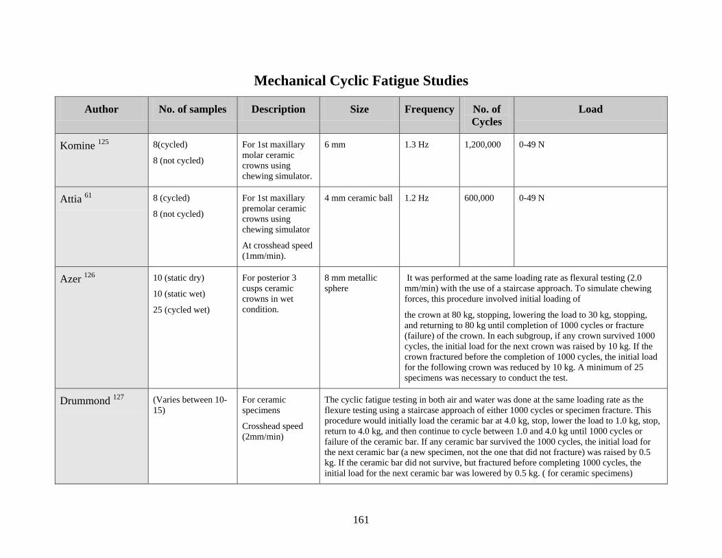
161
Mechanical Cyclic Fatigue Studies
Author No. of samples Description Size Frequency No. of
Cycles
Load
Komine 125
8(cycled)
8 (not cycled)
For 1st maxillary
molar ceramic
crowns using
chewing simulator.
6 mm 1.3 Hz 1,200,000 0-49 N
Attia 61
8 (cycled)
8 (not cycled)
For 1st maxillary
premolar ceramic
crowns using
chewing simulator
At crosshead speed
(1mm/min).
4 mm ceramic ball 1.2 Hz 600,000 0-49 N
Azer 126
10 (static dry)
10 (static wet)
25 (cycled wet)
For posterior 3
cusps ceramic
crowns in wet
condition.
8 mm metallic
sphere
It was performed at the same loading rate as flexural testing (2.0
mm/min) with the use of a staircase approach. To simulate chewing
forces, this procedure involved initial loading of
the crown at 80 kg, stopping, lowering the load to 30 kg, stopping,
and returning to 80 kg until completion of 1000 cycles or fracture
(failure) of the crown. In each subgroup, if any crown survived 1000
cycles, the initial load for the next crown was raised by 10 kg. If the
crown fractured before the completion of 1000 cycles, the initial load
for the following crown was reduced by 10 kg. A minimum of 25
specimens was necessary to conduct the test.
Drummond 127
(Varies between 10-
15)
For ceramic
specimens
Crosshead speed
(2mm/min)
The cyclic fatigue testing in both air and water was done at the same loading rate as the
flexure testing using a staircase approach of either 1000 cycles or specimen fracture. This
procedure would initially load the ceramic bar at 4.0 kg, stop, lower the load to 1.0 kg, stop,
return to 4.0 kg, and then continue to cycle between 1.0 and 4.0 kg until 1000 cycles or
failure of the ceramic bar. If any ceramic bar survived the 1000 cycles, the initial load for
the next ceramic bar (a new specimen, not the one that did not fracture) was raised by 0.5
kg. If the ceramic bar did not survive, but fractured before completing 1000 cycles, the
initial load for the next ceramic bar was lowered by 0.5 kg. ( for ceramic specimens)
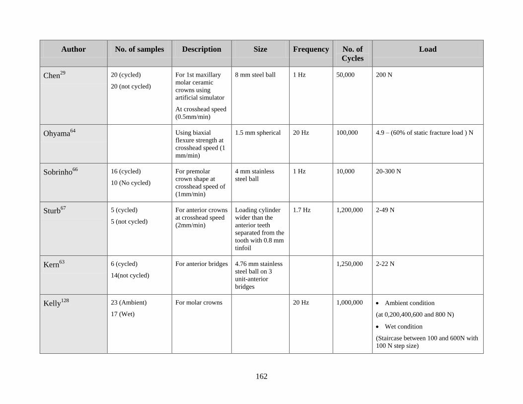
162
Author No. of samples Description Size Frequency No. of
Cycles
Load
Chen29
20 (cycled)
20 (not cycled)
For 1st maxillary
molar ceramic
crowns using
artificial simulator
At crosshead speed
(0.5mm/min)
8 mm steel ball 1 Hz 50,000 200 N
Ohyama64
Using biaxial
flexure strength at
crosshead speed (1
mm/min)
1.5 mm spherical 20 Hz 100,000 4.9 – (60% of static fracture load ) N
Sobrinho66
16 (cycled)
10 (No cycled)
For premolar
crown shape at
crosshead speed of
(1mm/min)
4 mm stainless
steel ball
1 Hz 10,000 20-300 N
Sturb67
5 (cycled)
5 (not cycled)
For anterior crowns
at crosshead speed
(2mm/min)
Loading cylinder
wider than the
anterior teeth
separated from the
tooth with 0.8 mm
tinfoil
1.7 Hz 1,200,000 2-49 N
Kern63
6 (cycled)
14(not cycled)
For anterior bridges 4.76 mm stainless
steel ball on 3
unit-anterior
bridges
1,250,000 2-22 N
Kelly128
23 (Ambient)
17 (Wet)
For molar crowns 20 Hz 1,000,000 Ambient condition
(at 0,200,400,600 and 800 N)
Wet condition
(Staircase between 100 and 600N with
100 N step size)
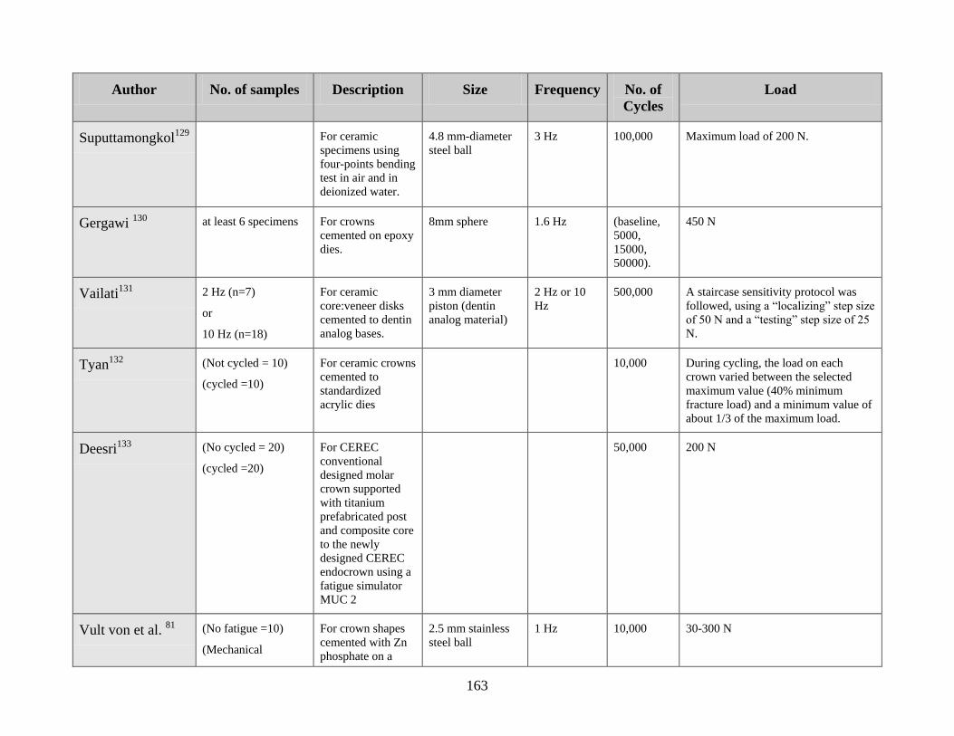
163
Author No. of samples Description Size Frequency No. of
Cycles
Load
Suputtamongkol129
For ceramic
specimens using
four-points bending
test in air and in
deionized water.
4.8 mm-diameter
steel ball
3 Hz 100,000 Maximum load of 200 N.
Gergawi 130
at least 6 specimens For crowns
cemented on epoxy
dies.
8mm sphere 1.6 Hz (baseline,
5000,
15000,
50000).
450 N
Vailati131
2 Hz (n=7)
or
10 Hz (n=18)
For ceramic
core:veneer disks
cemented to dentin
analog bases.
3 mm diameter
piston (dentin
analog material)
2 Hz or 10
Hz
500,000 A staircase sensitivity protocol was
followed, using a “localizing” step size
of 50 N and a “testing” step size of 25
N.
Tyan132
(Not cycled = 10)
(cycled =10)
For ceramic crowns
cemented to
standardized
acrylic dies
10,000 During cycling, the load on each
crown varied between the selected
maximum value (40% minimum
fracture load) and a minimum value of
about 1/3 of the maximum load.
Deesri133
(No cycled = 20)
(cycled =20)
For CEREC
conventional
designed molar
crown supported
with titanium
prefabricated post
and composite core
to the newly
designed CEREC
endocrown using a
fatigue simulator
MUC 2
50,000 200 N
Vult von et al. 81
(No fatigue =10)
(Mechanical
For crown shapes
cemented with Zn
phosphate on a
2.5 mm stainless
steel ball
1 Hz 10,000 30-300 N
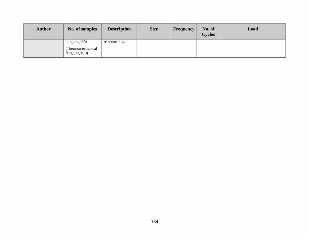
164
Author No. of samples Description Size Frequency No. of
Cycles
Load
fatiguing=10)
(Thermomechanical
fatiguing =10)
resinous dies.

165
Appendix II
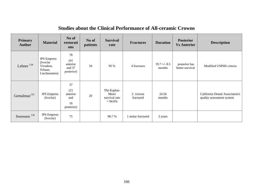
166
Studies about the Clinical Performance of All-ceramic Crowns
Primary
Author Material
No of
restorati
ons
No of
patients
Survival
rate Fractures Duration
Posterior
Vs Anterior Description
Lehner 134
IPS Empress
(Ivoclar
Vivadent,
Schaan,
Liechtenstein)
78
(41
anterior
and 37
posterior)
34 95 % 4 fractures 19.7 +/- 8.5
months
posterior has
better survival Modified USPHS criteria
Gemalmaz135
IPS Empress
(Ivoclar)
37
(21
anterior
and
16
posterior)
20
The Kaplan-
Meier
survival rate
= 94.6%
2 crowns
fractured
24.56
months
California Dental Association's
quality assessment system
Sorensen 136
IPS Empress
(Ivoclar) 75 98.7 % 1 molar fractured 3 years
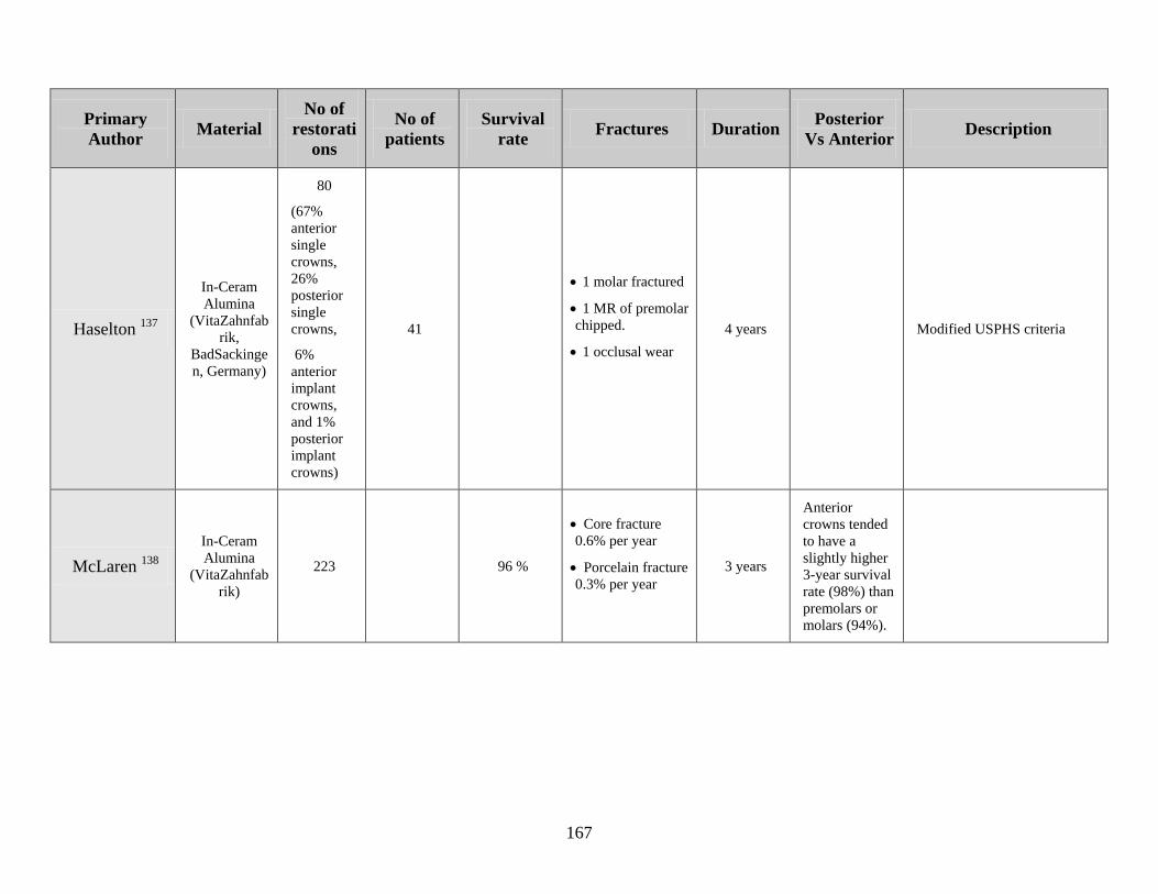
167
Primary
Author Material
No of
restorati
ons
No of
patients
Survival
rate Fractures Duration
Posterior
Vs Anterior Description
Haselton 137
In-Ceram
Alumina
(VitaZahnfab
rik,
BadSackinge
n, Germany)
80
(67%
anterior
single
crowns,
26%
posterior
single
crowns,
6%
anterior
implant
crowns,
and 1%
posterior
implant
crowns)
41
1 molar fractured
1 MR of premolar
chipped.
1 occlusal wear
4 years Modified USPHS criteria
McLaren 138
In-Ceram
Alumina
(VitaZahnfab
rik)
223 96 %
Core fracture
0.6% per year
Porcelain fracture
0.3% per year
3 years
Anterior
crowns tended
to have a
slightly higher
3-year survival
rate (98%) than
premolars or
molars (94%).
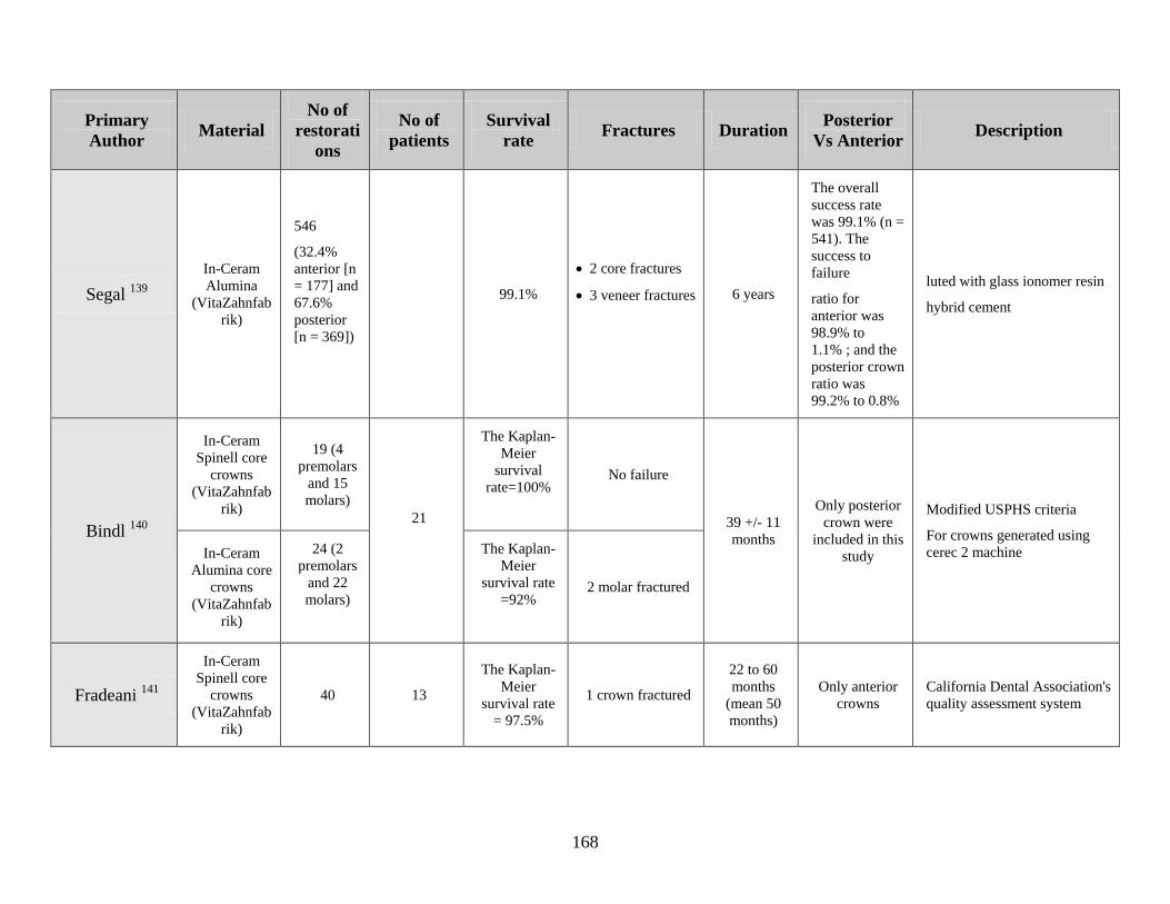
168
Primary
Author Material
No of
restorati
ons
No of
patients
Survival
rate Fractures Duration
Posterior
Vs Anterior Description
Segal 139
In-Ceram
Alumina
(VitaZahnfab
rik)
546
(32.4%
anterior [n
= 177] and
67.6%
posterior
[n = 369])
99.1%
2 core fractures
3 veneer fractures
6 years
The overall
success rate
was 99.1% (n =
541). The
success to
failure
ratio for
anterior was
98.9% to
1.1% ; and the
posterior crown
ratio was
99.2% to 0.8%
luted with glass ionomer resin
hybrid cement
Bindl 140
In-Ceram
Spinell core
crowns
(VitaZahnfab
rik)
19 (4
premolars
and 15
molars)
21
The Kaplan-
Meier
survival
rate=100%
No failure
39 +/- 11
months
Only posterior
crown were
included in this
study
Modified USPHS criteria
For crowns generated using
cerec 2 machine In-Ceram
Alumina core
crowns
(VitaZahnfab
rik)
24 (2
premolars
and 22
molars)
The Kaplan-
Meier
survival rate
=92%
2 molar fractured
Fradeani 141
In-Ceram
Spinell core
crowns
(VitaZahnfab
rik)
40 13
The Kaplan-
Meier
survival rate
= 97.5%
1 crown fractured
22 to 60
months
(mean 50
months)
Only anterior
crowns
California Dental Association's
quality assessment system
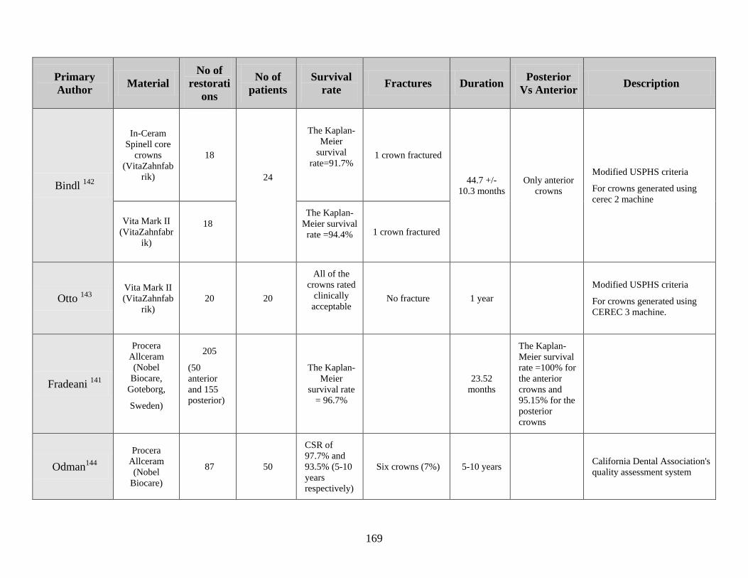
169
Primary
Author Material
No of
restorati
ons
No of
patients
Survival
rate Fractures Duration
Posterior
Vs Anterior Description
Bindl 142
In-Ceram
Spinell core
crowns
(VitaZahnfab
rik)
18
24
The Kaplan-
Meier
survival
rate=91.7%
1 crown fractured
44.7 +/-
10.3 months
Only anterior
crowns
Modified USPHS criteria
For crowns generated using
cerec 2 machine
Vita Mark II
(VitaZahnfabr
ik)
18
The Kaplan-
Meier survival
rate =94.4%
1 crown fractured
Otto 143
Vita Mark II
(VitaZahnfab
rik)
20 20
All of the
crowns rated
clinically
acceptable
No fracture 1 year
Modified USPHS criteria
For crowns generated using
CEREC 3 machine.
Fradeani 141
Procera
Allceram
(Nobel
Biocare,
Goteborg,
Sweden)
205
(50
anterior
and 155
posterior)
The Kaplan-
Meier
survival rate
= 96.7%
23.52
months
The Kaplan-
Meier survival
rate =100% for
the anterior
crowns and
95.15% for the
posterior
crowns
Odman144
Procera
Allceram
(Nobel
Biocare)
87 50
CSR of
97.7% and
93.5% (5-10
years
respectively)
Six crowns (7%) 5-10 years California Dental Association's
quality assessment system
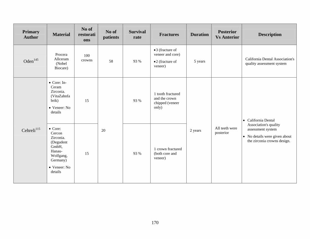
170
Primary
Author Material
No of
restorati
ons
No of
patients
Survival
rate Fractures Duration
Posterior
Vs Anterior Description
Oden145
Procera
Allceram
(Nobel
Biocare)
100
crowns
58 93 %
3 (fracture of
veneer and core)
2 (fracture of
veneer)
5 years California Dental Association's
quality assessment system
Cehreli115
Core: In-
Ceram
Zirconia.
(VitaZahnfa
brik)
Veneer: No
details
15
20
93 %
1 tooth fractured
and the crown
chipped (veneer
only)
2 years All teeth were
posterior
California Dental
Association's quality
assessment system
No details were given about
the zirconia crowns design.
Core:
Cercon
Zirconia.
(Degudent
GmbH,
Hanau-
Wolfgang,
Germany)
Veneer: No
details
15 93 %
1 crown fractured
(both core and
veneer)
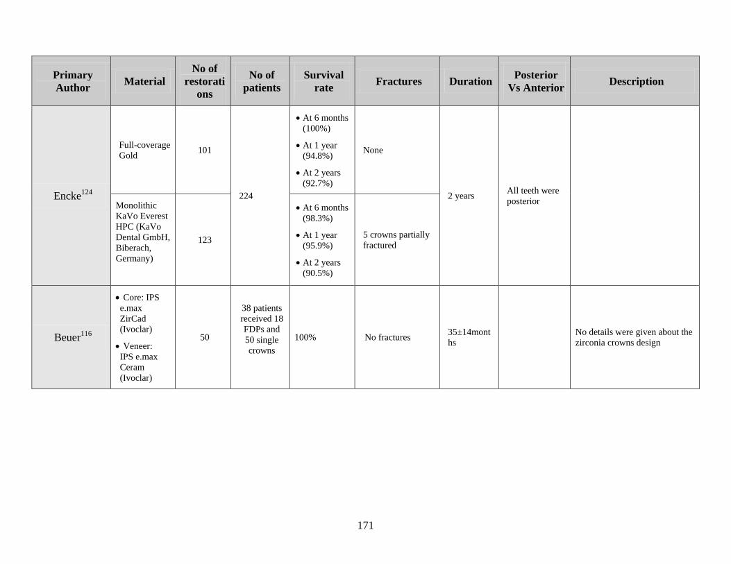
171
Primary
Author Material
No of
restorati
ons
No of
patients
Survival
rate Fractures Duration
Posterior
Vs Anterior Description
Encke124
Full-coverage
Gold 101
224
At 6 months
(100%)
At 1 year
(94.8%)
At 2 years
(92.7%)
None
2 years All teeth were
posterior
Monolithic
KaVo Everest
HPC (KaVo
Dental GmbH,
Biberach,
Germany)
123
At 6 months
(98.3%)
At 1 year
(95.9%)
At 2 years
(90.5%)
5 crowns partially
fractured
Beuer116
Core: IPS
e.max
ZirCad
(Ivoclar)
Veneer:
IPS e.max
Ceram
(Ivoclar)
50
38 patients
received 18
FDPs and
50 single
crowns
100% No fractures 35±14mont
hs
No details were given about the
zirconia crowns design
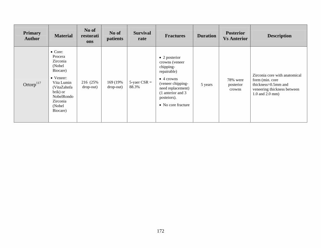
172
Primary
Author Material
No of
restorati
ons
No of
patients
Survival
rate Fractures Duration
Posterior
Vs Anterior Description
Ortorp117
Core:
Procera
Zirconia
(Nobel
Biocare)
Veneer:
Vita Lumin
(VitaZahnfa
brik) or
NobelRondo
Zirconia
(Nobel
Biocare)
216 (25%
drop-out)
169 (19%
drop-out)
5-yaer CSR =
88.3%
2 posterior
crowns (veneer
chipping-
repairable)
4 crowns
(veneer chipping-
need replacement)
(1 anterior and 3
posteiors).
No core fracture
5 years
78% were
posterior
crowns
Zirconia core with anatomical
form (min. core
thickness=0.5mm and
veneering thickness between
1.0 and 2.0 mm)
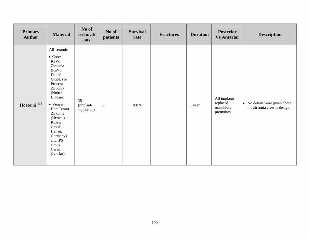
173
Primary
Author Material
No of
restorati
ons
No of
patients
Survival
rate Fractures Duration
Posterior
Vs Anterior Description
Hosseini 118
All-ceramic
Core:
KaVo
Zirconia
(KaVo
Dental
GmbH) or
Procera
Zirconia
(Nobel
Biocare)
Veneer:
HeraCeram
Zirkonia
(Heraeus
Kulzer
GmbH,
Hanau,
Germany)
and IPS
e.max
Ceram
(Ivoclar)
38
(implant-
supported)
36 100 % 1 year
All implants
replaced
mandibular
premolars
No details were given about
the zirconia crowns design.
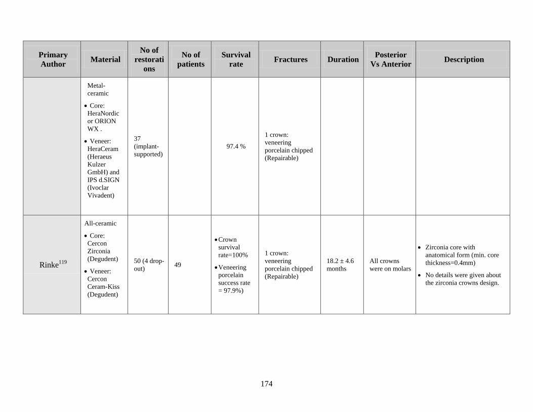
174
Primary
Author Material
No of
restorati
ons
No of
patients
Survival
rate Fractures Duration
Posterior
Vs Anterior Description
Metal-
ceramic
Core:
HeraNordic
or ORION
WX .
Veneer:
HeraCeram
(Heraeus
Kulzer
GmbH) and
IPS d.SIGN
(Ivoclar
Vivadent)
37
(implant-
supported)
97.4 %
1 crown:
veneering
porcelain chipped
(Repairable)
Rinke119
All-ceramic
Core:
Cercon
Zirconia
(Degudent)
Veneer:
Cercon
Ceram-Kiss
(Degudent)
50 (4 drop-
out) 49
Crown
survival
rate=100%
Veneering
porcelain
success rate
= 97.9%)
1 crown:
veneering
porcelain chipped
(Repairable)
18.2 ± 4.6
months
All crowns
were on molars
Zirconia core with
anatomical form (min. core
thickness=0.4mm)
No details were given about
the zirconia crowns design.
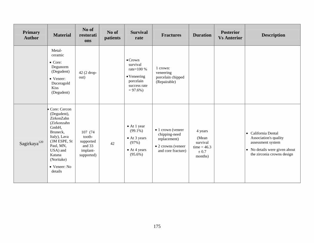
175
Primary
Author Material
No of
restorati
ons
No of
patients
Survival
rate Fractures Duration
Posterior
Vs Anterior Description
Metal-
ceramic
Core:
Degunorm
(Degudent)
Veneer:
Duceragold
Kiss
(Degudent)
42 (2 drop-
out)
Crown
survival
rate=100 %
Veneering
porcelain
success rate
= 97.6%)
1 crown:
veneering
porcelain chipped
(Repairable)
Sagirkaya120
Core: Cercon
(Degudent),
ZirkonZahn
(Zirkonzahn
GmbH,
Bruneck,
Italy), Lava
(3M ESPE, St
Paul, MN,
USA) and
Katana
(Noritake)
Veneer: No
details
107 (74
tooth-
supported
and 33
implant-
supported)
42
At 1 year
(99.1%)
At 3 years
(97%)
At 4 years
(95.6%)
1 crown (veneer
chipping-need
replacement)
2 crowns (veneer
and core fracture)
4 years
(Mean
survival
time = 46.3
± 0.7
months)
California Dental
Association's quality
assessment system
No details were given about
the zirconia crowns design
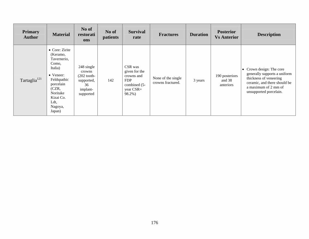
176
Primary
Author Material
No of
restorati
ons
No of
patients
Survival
rate Fractures Duration
Posterior
Vs Anterior Description
Tartaglia121
Core: Zirite
(Keramo,
Tavernerio,
Como,
Italia)
Veneer:
Feldspathic
porcelain
(CZR,
Noritake
Kizai Co.
Ldt,
Nagoya,
Japan)
248 single
crowns
(202 tooth-
supported,
36
implant-
supported
142
CSR was
given for the
crowns and
FDP
combined (5-
year CSR=
98.2%)
None of the single
crowns fractured. 3 years
190 posteriors
and 38
anteriors
Crown design: The core
generally supports a uniform
thickness of veneering
ceramic, and there should be
a maximum of 2 mm of
unsupported porcelain.
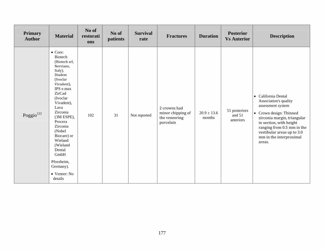
177
Primary
Author Material
No of
restorati
ons
No of
patients
Survival
rate Fractures Duration
Posterior
Vs Anterior Description
Poggio122
Core:
Biotech
(Biotech srl, Nerviano, Italy), Diadem (Ivoclar
Vivadent),
IPS e.max
ZirCad
(Ivoclar
Vivadent),
Lava
Zirconia
(3M ESPE),
Procera
Zirconia
(Nobel
Biocare) or
Wieland
(Wieland
Dental
GmbH
Pforzheim,
Germany).
Veneer: No
details
102 31 Not reported
2 crowns had minor chipping of the veneering porcelain
20.9 ± 13.6
months
51 posteriors
and 51
anteriors
California Dental
Association's quality
assessment system
Crown design: Thinned zirconia margin, triangular in section, with height ranging from 0.5 mm in the vestibular areas up to 3.0
mm in the interproximal areas.
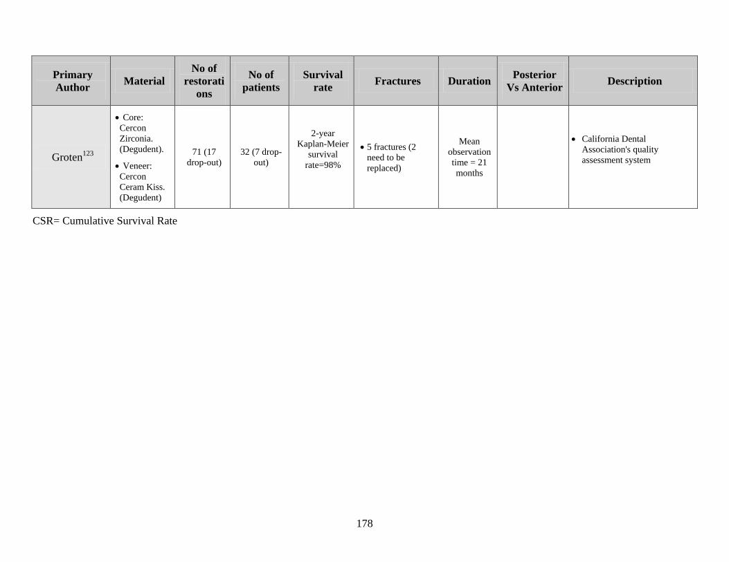
178
Primary
Author Material
No of
restorati
ons
No of
patients
Survival
rate Fractures Duration
Posterior
Vs Anterior Description
Groten123
Core:
Cercon
Zirconia.
(Degudent).
Veneer:
Cercon
Ceram Kiss.
(Degudent)
71 (17
drop-out)
32 (7 drop-
out)
2-year
Kaplan-Meier
survival
rate=98%
5 fractures (2
need to be
replaced)
Mean
observation
time = 21
months
California Dental
Association's quality
assessment system
CSR= Cumulative Survival Rate

179
Appendix III
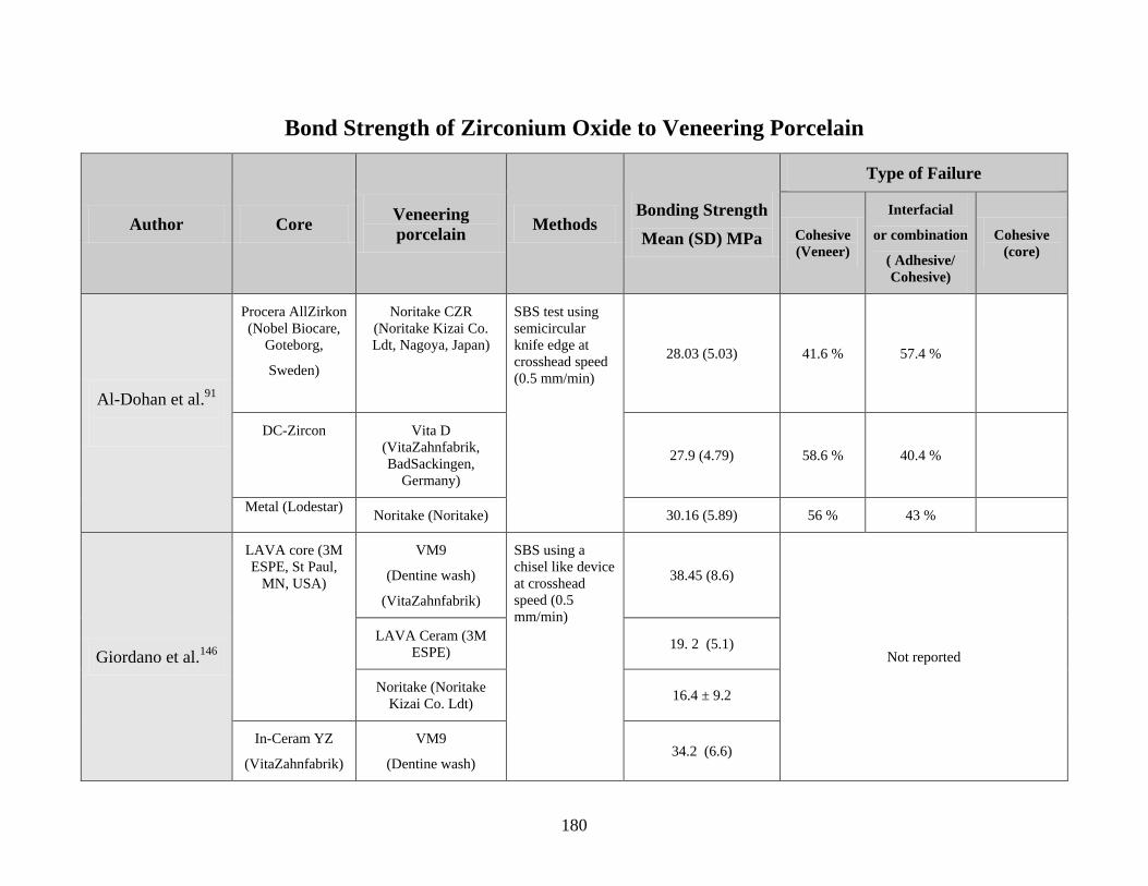
180
Bond Strength of Zirconium Oxide to Veneering Porcelain
Author Core Veneering
porcelain Methods
Bonding Strength
Mean (SD) MPa
Type of Failure
Cohesive
(Veneer)
Interfacial
or combination
( Adhesive/
Cohesive)
Cohesive
(core)
Al-Dohan et al.91
Procera AllZirkon
(Nobel Biocare,
Goteborg,
Sweden)
Noritake CZR
(Noritake Kizai Co.
Ldt, Nagoya, Japan)
SBS test using
semicircular
knife edge at
crosshead speed
(0.5 mm/min)
28.03 (5.03) 41.6 % 57.4 %
DC-Zircon Vita D
(VitaZahnfabrik,
BadSackingen,
Germany)
27.9 (4.79) 58.6 % 40.4 %
Metal (Lodestar) Noritake (Noritake) 30.16 (5.89) 56 % 43 %
Giordano et al.146
LAVA core (3M
ESPE, St Paul,
MN, USA)
VM9
(Dentine wash)
(VitaZahnfabrik)
SBS using a
chisel like device
at crosshead
speed (0.5
mm/min)
38.45 (8.6)
Not reported
LAVA Ceram (3M
ESPE) 19. 2 (5.1)
Noritake (Noritake
Kizai Co. Ldt) 16.4 ± 9.2
In-Ceram YZ
(VitaZahnfabrik)
VM9
(Dentine wash) 34.2 (6.6)
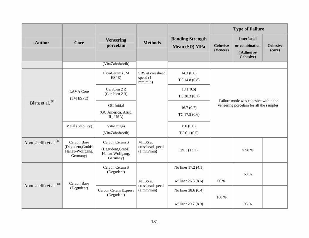
181
Author Core Veneering
porcelain Methods
Bonding Strength
Mean (SD) MPa
Type of Failure
Cohesive
(Veneer)
Interfacial
or combination
( Adhesive/
Cohesive)
Cohesive
(core)
(VitaZahnfabrik)
Blatz et al. 96
LAVA Core
(3M ESPE)
LavaCeram (3M
ESPE)
SBS at crosshead
speed (1
mm/min)
14.3 (0.6)
TC 14.8 (0.8)
Failure mode was cohesive within the
veneering porcelain for all the samples.
Cerabien ZR
(Cerabien ZR)
18.1(0.6)
TC 20.3 (0.7)
GC Initial
(GC America, Alsip,
IL, USA)
16.7 (0.7)
TC 17.5 (0.6)
Metal (Stability) VitaOmega
(VitaZahnfabrik)
8.0 (0.6)
TC 6.1 (0.5)
Aboushelib et al. 85
Cercon Base
(Degudent,GmbH,
Hanau-Wolfgang,
Germany)
Cercon Ceram S
(Degudent,GmbH,
Hanau-Wolfgang,
Germany)
MTBS at
crosshead speed
(1 mm/min) 29.1 (13.7) > 90 %
Aboushelib et al. 84
Cercon Base
(Degudent)
Cercon Ceram S
(Degudent)
MTBS at
crosshead speed
(1 mm/min)
No liner 17.2 (4.1)
w/ liner 26.3 (8.6)
60 %
60 %
Cercon Ceram Express
(Degudent)
No liner 38.6 (6.4)
w/ liner 29.7 (8.9)
100 %
95 %
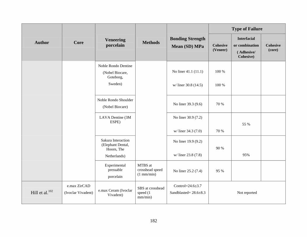
182
Author Core Veneering
porcelain Methods
Bonding Strength
Mean (SD) MPa
Type of Failure
Cohesive
(Veneer)
Interfacial
or combination
( Adhesive/
Cohesive)
Cohesive
(core)
Noble Rondo Dentine
(Nobel Biocare,
Goteborg,
Sweden)
No liner 41.1 (11.1)
w/ liner 30.8 (14.5)
100 %
100 %
Noble Rondo Shoulder
(Nobel Biocare) No liner 39.3 (9.6) 70 %
LAVA Dentine (3M
ESPE)
No liner 30.9 (7.2)
w/ liner 34.3 (7.0)
70 %
55 %
Sakura Interaction
(Elephant Dental,
Hoorn, The
Netherlands)
No liner 19.9 (9.2)
w/ liner 23.8 (7.8)
90 %
95%
Experimental
pressable
porcelain
MTBS at
crosshead speed
(1 mm/min) No liner 25.2 (7.4) 95 %
Hill et al.102
e.max ZirCAD
(Ivoclar Vivadent)
e.max Ceram (Ivoclar
Vivadent)
SBS at crosshead
speed (1
mm/min)
Control=24.6±3.7
Sandblasted= 28.6±8.3
Not reported
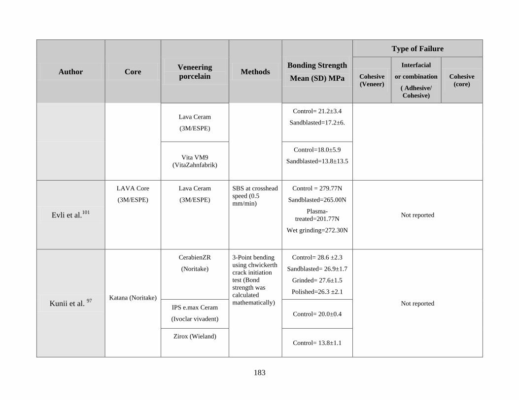
183
Author Core Veneering
porcelain Methods
Bonding Strength
Mean (SD) MPa
Type of Failure
Cohesive
(Veneer)
Interfacial
or combination
( Adhesive/
Cohesive)
Cohesive
(core)
Lava Ceram
(3M/ESPE)
Control= 21.2±3.4
Sandblasted=17.2±6.
Vita VM9
(VitaZahnfabrik)
Control=18.0±5.9
Sandblasted=13.8±13.5
Evli et al.101
LAVA Core
(3M/ESPE)
Lava Ceram
(3M/ESPE)
SBS at crosshead
speed (0.5
mm/min)
Control = 279.77N
Sandblasted=265.00N
Plasma-
treated=201.77N
Wet grinding=272.30N
Not reported
Kunii et al. 97
Katana (Noritake)
CerabienZR
(Noritake)
3-Point bending
using chwickerth
crack initiation
test (Bond
strength was
calculated
mathematically)
Control= 28.6 ±2.3
Sandblasted= 26.9±1.7
Grinded= 27.6±1.5
Polished=26.3 ±2.1
Not reported IPS e.max Ceram
(Ivoclar vivadent) Control= 20.0±0.4
Zirox (Wieland) Control= 13.8±1.1
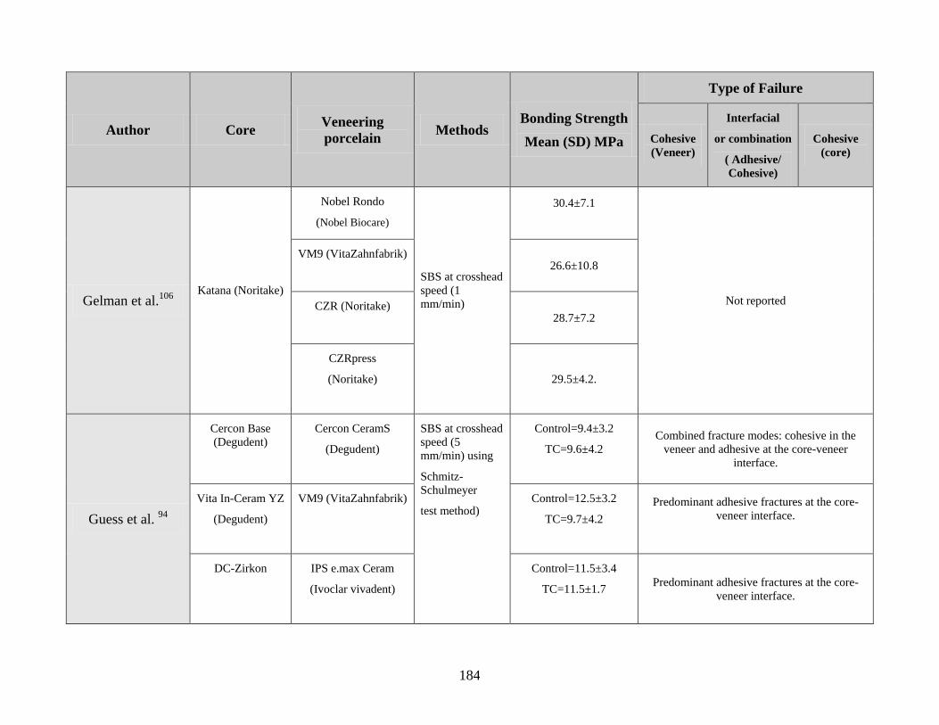
184
Author Core Veneering
porcelain Methods
Bonding Strength
Mean (SD) MPa
Type of Failure
Cohesive
(Veneer)
Interfacial
or combination
( Adhesive/
Cohesive)
Cohesive
(core)
Gelman et al.106
Katana (Noritake)
Nobel Rondo
(Nobel Biocare)
SBS at crosshead
speed (1
mm/min)
30.4±7.1
Not reported
VM9 (VitaZahnfabrik)
26.6±10.8
CZR (Noritake) 28.7±7.2
CZRpress
(Noritake)
29.5±4.2.
Guess et al. 94
Cercon Base
(Degudent)
Cercon CeramS
(Degudent)
SBS at crosshead
speed (5
mm/min) using
Schmitz-
Schulmeyer
test method)
Control=9.4±3.2
TC=9.6±4.2
Combined fracture modes: cohesive in the
veneer and adhesive at the core-veneer
interface.
Vita In-Ceram YZ
(Degudent)
VM9 (VitaZahnfabrik)
Control=12.5±3.2
TC=9.7±4.2
Predominant adhesive fractures at the core-
veneer interface.
DC-Zirkon
IPS e.max Ceram
(Ivoclar vivadent)
Control=11.5±3.4
TC=11.5±1.7
Predominant adhesive fractures at the core-
veneer interface.
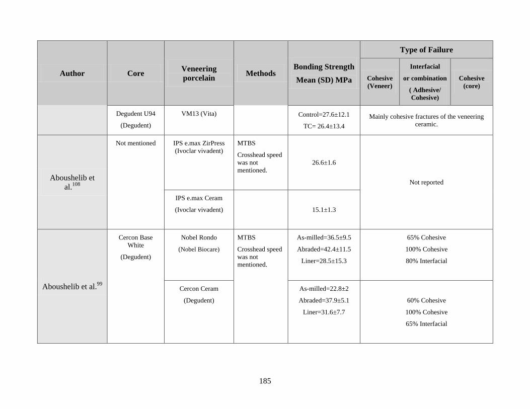
185
Author Core Veneering
porcelain Methods
Bonding Strength
Mean (SD) MPa
Type of Failure
Cohesive
(Veneer)
Interfacial
or combination
( Adhesive/
Cohesive)
Cohesive
(core)
Degudent U94
(Degudent)
VM13 (Vita)
Control=27.6±12.1
TC= 26.4±13.4
Mainly cohesive fractures of the veneering
ceramic.
Aboushelib et
al.108
Not mentioned IPS e.max ZirPress
(Ivoclar vivadent)
MTBS
Crosshead speed
was not
mentioned.
26.6±1.6
Not reported
IPS e.max Ceram
(Ivoclar vivadent)
15.1±1.3
Aboushelib et al.99
Cercon Base
White
(Degudent)
Nobel Rondo
(Nobel Biocare)
MTBS
Crosshead speed
was not
mentioned.
As-milled=36.5±9.5
Abraded=42.4±11.5
Liner=28.5±15.3
65% Cohesive
100% Cohesive
80% Interfacial
Cercon Ceram
(Degudent)
As-milled=22.8±2
Abraded=37.9±5.1
Liner=31.6±7.7
60% Cohesive
100% Cohesive
65% Interfacial
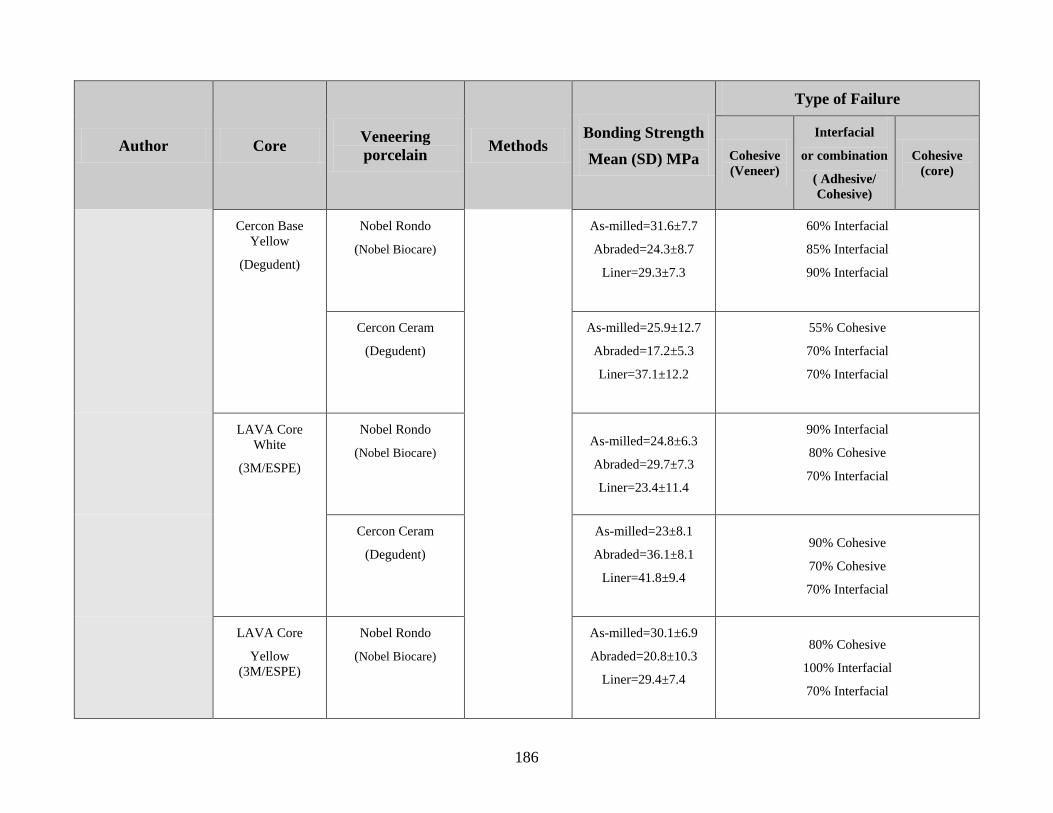
186
Author Core Veneering
porcelain Methods
Bonding Strength
Mean (SD) MPa
Type of Failure
Cohesive
(Veneer)
Interfacial
or combination
( Adhesive/
Cohesive)
Cohesive
(core)
Cercon Base
Yellow
(Degudent)
Nobel Rondo
(Nobel Biocare)
As-milled=31.6±7.7
Abraded=24.3±8.7
Liner=29.3±7.3
60% Interfacial
85% Interfacial
90% Interfacial
Cercon Ceram
(Degudent)
As-milled=25.9±12.7
Abraded=17.2±5.3
Liner=37.1±12.2
55% Cohesive
70% Interfacial
70% Interfacial
LAVA Core
White
(3M/ESPE)
Nobel Rondo
(Nobel Biocare) As-milled=24.8±6.3
Abraded=29.7±7.3
Liner=23.4±11.4
90% Interfacial
80% Cohesive
70% Interfacial
Cercon Ceram
(Degudent)
As-milled=23±8.1
Abraded=36.1±8.1
Liner=41.8±9.4
90% Cohesive
70% Cohesive
70% Interfacial
LAVA Core
Yellow
(3M/ESPE)
Nobel Rondo
(Nobel Biocare)
As-milled=30.1±6.9
Abraded=20.8±10.3
Liner=29.4±7.4
80% Cohesive
100% Interfacial
70% Interfacial
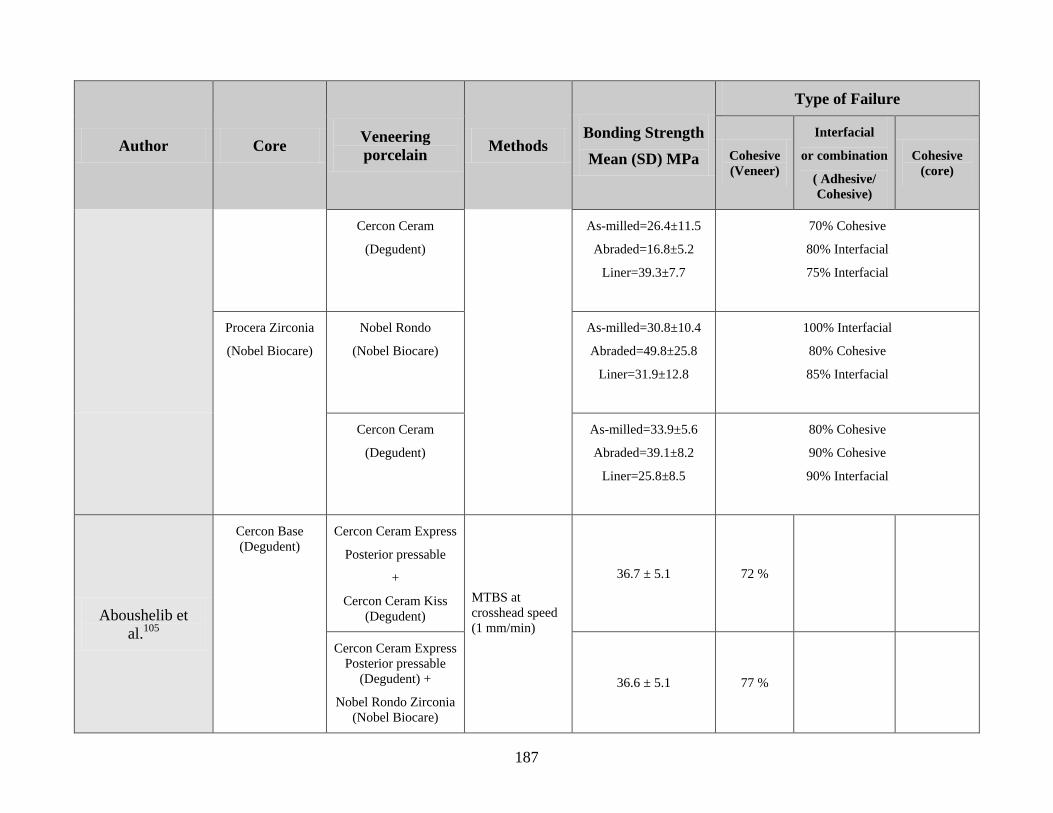
187
Author Core Veneering
porcelain Methods
Bonding Strength
Mean (SD) MPa
Type of Failure
Cohesive
(Veneer)
Interfacial
or combination
( Adhesive/
Cohesive)
Cohesive
(core)
Cercon Ceram
(Degudent)
As-milled=26.4±11.5
Abraded=16.8±5.2
Liner=39.3±7.7
70% Cohesive
80% Interfacial
75% Interfacial
Procera Zirconia
(Nobel Biocare)
Nobel Rondo
(Nobel Biocare)
As-milled=30.8±10.4
Abraded=49.8±25.8
Liner=31.9±12.8
100% Interfacial
80% Cohesive
85% Interfacial
Cercon Ceram
(Degudent)
As-milled=33.9±5.6
Abraded=39.1±8.2
Liner=25.8±8.5
80% Cohesive
90% Cohesive
90% Interfacial
Aboushelib et
al.105
Cercon Base
(Degudent)
Cercon Ceram Express
Posterior pressable
+
Cercon Ceram Kiss
(Degudent)
MTBS at
crosshead speed
(1 mm/min)
36.7 ± 5.1 72 %
Cercon Ceram Express
Posterior pressable
(Degudent) +
Nobel Rondo Zirconia
(Nobel Biocare)
36.6 ± 5.1 77 %
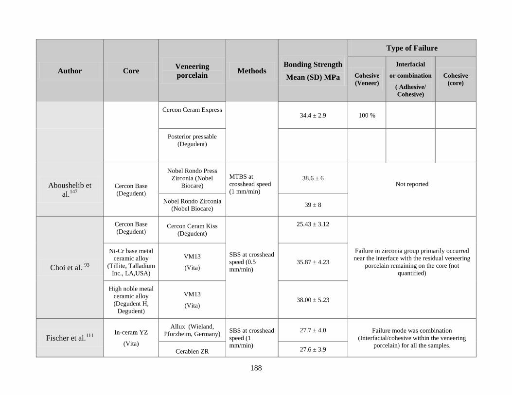
188
Author Core Veneering
porcelain Methods
Bonding Strength
Mean (SD) MPa
Type of Failure
Cohesive
(Veneer)
Interfacial
or combination
( Adhesive/
Cohesive)
Cohesive
(core)
Cercon Ceram Express
34.4 ± 2.9 100 %
Posterior pressable
(Degudent)
Aboushelib et
al.147
Cercon Base
(Degudent)
Nobel Rondo Press
Zirconia (Nobel
Biocare)
MTBS at
crosshead speed
(1 mm/min)
38.6 ± 6 Not reported
Nobel Rondo Zirconia
(Nobel Biocare) 39 ± 8
Choi et al. 93
Cercon Base
(Degudent) Cercon Ceram Kiss
(Degudent)
SBS at crosshead
speed (0.5
mm/min)
25.43 ± 3.12
Failure in zirconia group primarily occurred
near the interface with the residual veneering
porcelain remaining on the core (not
quantified)
Ni-Cr base metal
ceramic alloy
(Tillite, Talladium
Inc., LA,USA)
VM13
(Vita) 35.87 ± 4.23
High noble metal
ceramic alloy
(Degudent H,
Degudent)
VM13
(Vita) 38.00 ± 5.23
Fischer et al.111
In-ceram YZ
(Vita)
Allux (Wieland,
Pforzheim, Germany) SBS at crosshead
speed (1
mm/min)
27.7 ± 4.0 Failure mode was combination
(Interfacial/cohesive within the veneering
porcelain) for all the samples. Cerabien ZR 27.6 ± 3.9
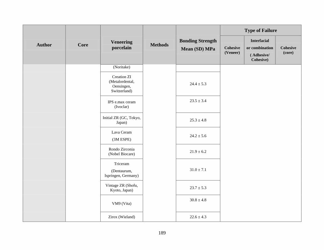
189
Author Core Veneering
porcelain Methods
Bonding Strength
Mean (SD) MPa
Type of Failure
Cohesive
(Veneer)
Interfacial
or combination
( Adhesive/
Cohesive)
Cohesive
(core)
(Noritake)
Creation ZI
(Metalordental,
Oensingen,
Switzerland)
24.4 ± 5.3
IPS e.max ceram
(Ivoclar)
23.5 ± 3.4
Initial ZR (GC, Tokyo,
Japan) 25.3 ± 4.8
Lava Ceram
(3M ESPE) 24.2 ± 5.6
Rondo Zirconia
(Nobel Biocare) 21.9 ± 6.2
Triceram
(Dentaurum,
Ispringen, Germany)
31.0 ± 7.1
Vintage ZR (Shofu,
Kyoto, Japan) 23.7 ± 5.3
VM9 (Vita) 30.8 ± 4.8
Zirox (Wieland) 22.6 ± 4.3
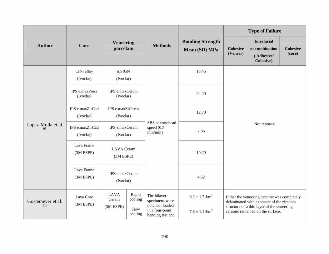
190
Author Core Veneering
porcelain Methods
Bonding Strength
Mean (SD) MPa
Type of Failure
Cohesive
(Veneer)
Interfacial
or combination
( Adhesive/
Cohesive)
Cohesive
(core)
Lopez-Molla et al. 95
CrNi alloy
(Ivoclar)
d.SIGN
(Ivoclar)
SBS at crosshead
speed (0.5
mm/min)
13.45
Not reported
IPS e.maxPress
(Ivoclar)
IPS e.maxCeram
(Ivoclar) 24.20
IPS e.maxZirCad
(Ivoclar)
IPS e.maxZirPress
(Ivoclar) 12.70
IPS e.maxZirCad
(Ivoclar)
IPS e.maxCeram
(Ivoclar) 7.86
Lava Frame
(3M ESPE)
LAVA Ceram
(3M ESPE) 10.20
Lava Frame
(3M ESPE)
IPS e.maxCeram
(Ivoclar) 4.62
Gostemeyer et al. 113
Lava Core
(3M ESPE)
LAVA
Ceram
(3M ESPE)
Rapid
cooling The bilayer
specimens were
notched; loaded
in a four-point
bending test and
8.2 ± 1.7 J/m2 Either the veneering ceramic was completely
delaminated with exposure of the zirconia
structure or a thin layer of the veneering
ceramic remained on the surface. Slow
cooling 7.5 ± 1.1 J/m2
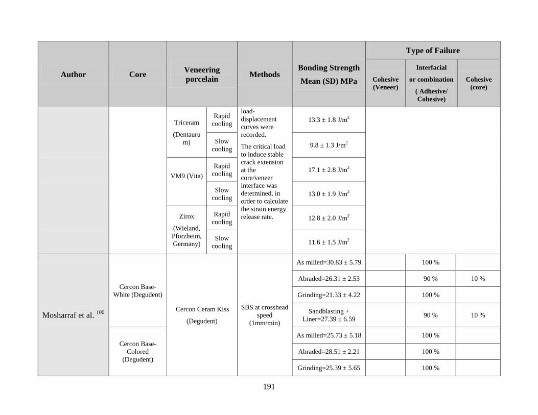
191
Author Core Veneering
porcelain Methods
Bonding Strength
Mean (SD) MPa
Type of Failure
Cohesive
(Veneer)
Interfacial
or combination
( Adhesive/
Cohesive)
Cohesive
(core)
Triceram
(Dentauru
m)
Rapid
cooling
load-
displacement
curves were
recorded.
The critical load
to induce stable
crack extension
at the
core/veneer
interface was
determined, in
order to calculate
the strain energy
release rate.
13.3 ± 1.8 J/m2
Slow
cooling 9.8 ± 1.3 J/m2
VM9 (Vita)
Rapid
cooling 17.1 ± 2.8 J/m2
Slow
cooling 13.0 ± 1.9 J/m2
Zirox
(Wieland,
Pforzheim,
Germany)
Rapid
cooling 12.8 ± 2.0 J/m2
Slow
cooling 11.6 ± 1.5 J/m2
Mosharraf et al. 100
Cercon Base-
White (Degudent)
Cercon Ceram Kiss
(Degudent)
SBS at crosshead
speed
(1mm/min)
As milled=30.83 ± 5.79 100 %
Abraded=26.31 ± 2.53 90 % 10 %
Grinding=21.33 ± 4.22 100 %
Sandblasting +
Liner=27.39 ± 6.59 90 % 10 %
Cercon Base-
Colored
(Degudent)
As milled=25.73 ± 5.18 100 %
Abraded=28.51 ± 2.21 100 %
Grinding=25.39 ± 5.65 100 %
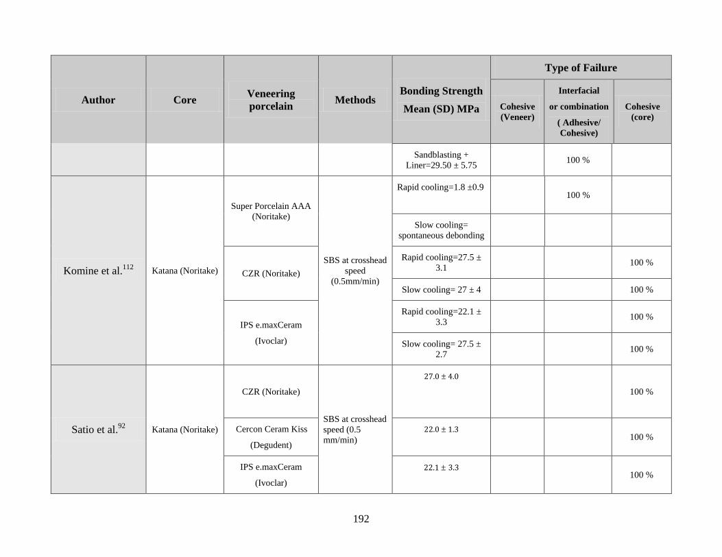
192
Author Core Veneering
porcelain Methods
Bonding Strength
Mean (SD) MPa
Type of Failure
Cohesive
(Veneer)
Interfacial
or combination
( Adhesive/
Cohesive)
Cohesive
(core)
Sandblasting +
Liner=29.50 ± 5.75 100 %
Komine et al.112
Katana (Noritake)
Super Porcelain AAA
(Noritake)
SBS at crosshead
speed
(0.5mm/min)
Rapid cooling=1.8 ±0.9
100 %
Slow cooling=
spontaneous debonding
CZR (Noritake)
Rapid cooling=27.5 ±
3.1 100 %
Slow cooling= 27 ± 4 100 %
IPS e.maxCeram
(Ivoclar)
Rapid cooling=22.1 ±
3.3 100 %
Slow cooling= 27.5 ±
2.7 100 %
Satio et al.92
Katana (Noritake)
CZR (Noritake)
SBS at crosshead
speed (0.5
mm/min)
27.0 ± 4.0
100 %
Cercon Ceram Kiss
(Degudent)
22.0 ± 1.3
100 %
IPS e.maxCeram
(Ivoclar)
22.1 ± 3.3
100 %
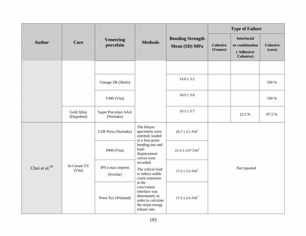
193
Author Core Veneering
porcelain Methods
Bonding Strength
Mean (SD) MPa
Type of Failure
Cohesive
(Veneer)
Interfacial
or combination
( Adhesive/
Cohesive)
Cohesive
(core)
Vintage ZR (Shofu) 24.8 ± 3.2
100 %
VM9 (Vita) 30.9 ± 3.8
100 %
Gold Alloy
(Degudent)
Super Porcelain AAA
(Noritake)
25.2 ± 5.7
12.5 % 87.5 %
Choi et al.98
In-Ceram YZ
(Vita)
CZR Press (Noritake)
The bilayer
specimens were
notched; loaded
in a four-point
bending test and
load-
displacement
curves were
recorded.
The critical load
to induce stable
crack extension
at the
core/veneer
interface was
determined, in
order to calculate
the strain energy
release rate.
26.7 ± 2.1 J/m2
Not reported
PM9 (Vita) 21.3 ± 2.07 J/m2
IPS e.max zirpress
(Ivoclar) 17.3 ± 3.2 J/m2
Press Xzr (Wieland) 17.2 ± 2.6 J/m2
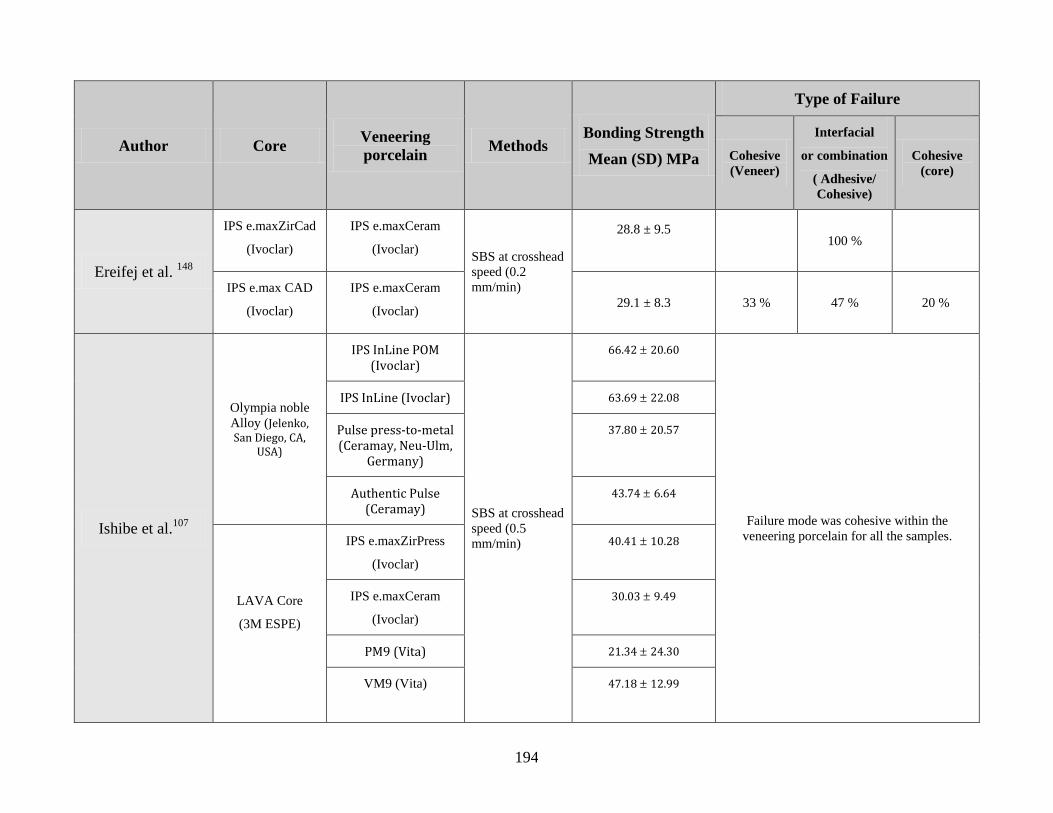
194
Author Core Veneering
porcelain Methods
Bonding Strength
Mean (SD) MPa
Type of Failure
Cohesive
(Veneer)
Interfacial
or combination
( Adhesive/
Cohesive)
Cohesive
(core)
Ereifej et al. 148
IPS e.maxZirCad
(Ivoclar)
IPS e.maxCeram
(Ivoclar) SBS at crosshead
speed (0.2
mm/min)
28.8 ± 9.5
100 %
IPS e.max CAD
(Ivoclar)
IPS e.maxCeram
(Ivoclar) 29.1 ± 8.3 33 % 47 % 20 %
Ishibe et al.107
Olympia noble
Alloy (Jelenko, San Diego, CA,
USA)
IPS InLine POM (Ivoclar)
SBS at crosshead
speed (0.5
mm/min)
66.42 ± 20.60
Failure mode was cohesive within the
veneering porcelain for all the samples.
IPS InLine (Ivoclar) 63.69 ± 22.08
Pulse press-to-metal (Ceramay, Neu-Ulm,
Germany)
37.80 ± 20.57
Authentic Pulse (Ceramay)
43.74 ± 6.64
LAVA Core
(3M ESPE)
IPS e.maxZirPress
(Ivoclar)
40.41 ± 10.28
IPS e.maxCeram
(Ivoclar)
30.03 ± 9.49
PM9 (Vita) 21.34 ± 24.30
VM9 (Vita)
47.18 ± 12.99
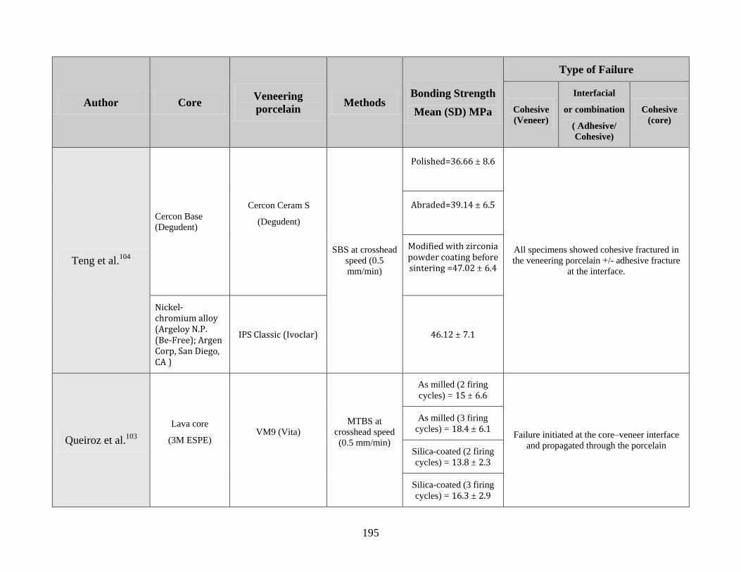
195
Author Core Veneering
porcelain Methods
Bonding Strength
Mean (SD) MPa
Type of Failure
Cohesive
(Veneer)
Interfacial
or combination
( Adhesive/
Cohesive)
Cohesive
(core)
Teng et al.104
Cercon Base
(Degudent)
Cercon Ceram S
(Degudent)
SBS at crosshead
speed (0.5
mm/min)
Polished=36.66 ± 8.6
All specimens showed cohesive fractured in
the veneering porcelain +/- adhesive fracture
at the interface.
Abraded=39.14 ± 6.5
Modified with zirconia powder coating before sintering =47.02 ± 6.4
Nickel-chromium alloy (Argeloy N.P. (Be-Free); Argen Corp, San Diego, CA )
IPS Classic (Ivoclar) 46.12 ± 7.1
Queiroz et al.103
Lava core
(3M ESPE)
VM9 (Vita)
MTBS at
crosshead speed
(0.5 mm/min)
As milled (2 firing
cycles) = 15 ± 6.6
Failure initiated at the core–veneer interface
and propagated through the porcelain
As milled (3 firing
cycles) = 18.4 ± 6.1
Silica-coated (2 firing
cycles) = 13.8 ± 2.3
Silica-coated (3 firing
cycles) = 16.3 ± 2.9
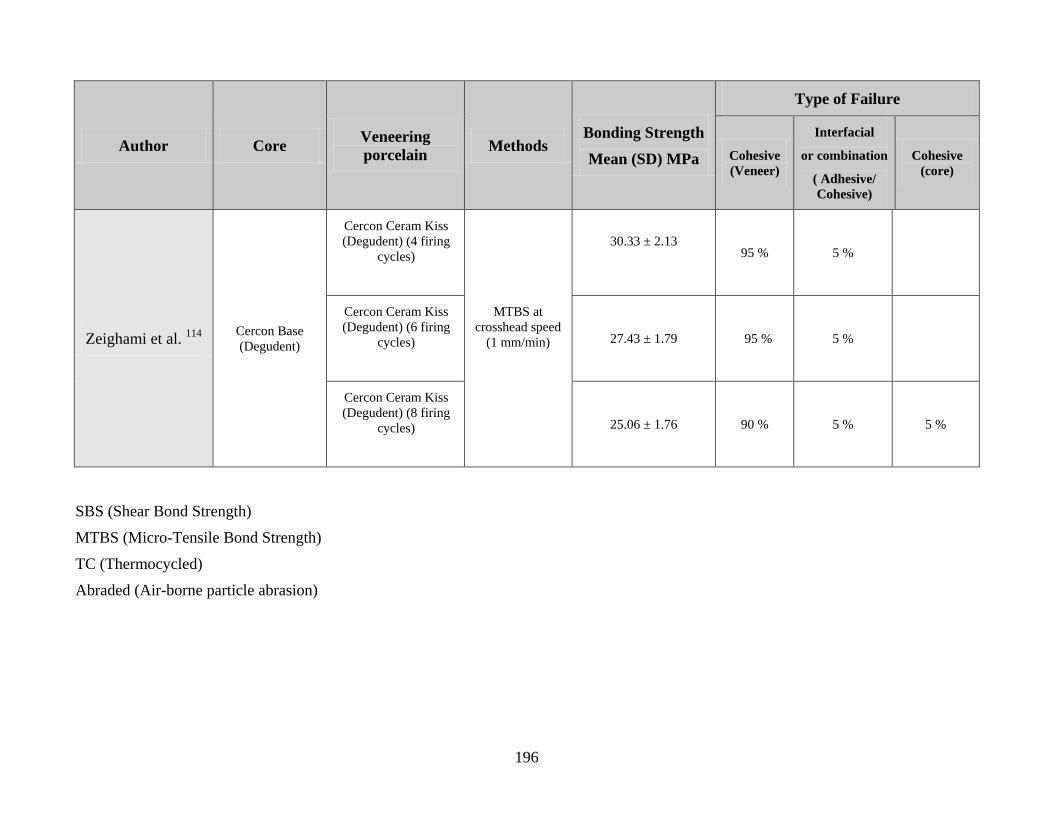
196
Author Core Veneering
porcelain Methods
Bonding Strength
Mean (SD) MPa
Type of Failure
Cohesive
(Veneer)
Interfacial
or combination
( Adhesive/
Cohesive)
Cohesive
(core)
Zeighami et al. 114
Cercon Base
(Degudent)
Cercon Ceram Kiss
(Degudent) (4 firing
cycles)
MTBS at
crosshead speed
(1 mm/min)
30.33 ± 2.13
95 % 5 %
Cercon Ceram Kiss
(Degudent) (6 firing
cycles)
27.43 ± 1.79 95 % 5 %
Cercon Ceram Kiss
(Degudent) (8 firing
cycles)
25.06 ± 1.76 90 % 5 % 5 %
SBS (Shear Bond Strength)
MTBS (Micro-Tensile Bond Strength)
TC (Thermocycled)
Abraded (Air-borne particle abrasion)
197
Reference
198
1. Rosenstiel SF, Land MF, Fujimoto J. Contemporary fixed prosthodontics. 3rd
ed.
St. Louis: Mosby; 2001. p. 262-71.
2. Shillingburg HT. Fundamentals of fixed prosthodontics. 3rd
ed. Chicago:
Quintessence Pub. Co; 1997. p. 433-54.
3. O'Brien WJ. Dental materials and their selection. 3rd
ed. Chicago: Quintessence
Pub. Co; 2002.
4. Kelly JR. Dental ceramics: current thinking and trends. Dent Clin North Am
2004;48(2):viii, 513-viii, 30.
5. Anusavice KJ, Phillips RW. Phillips' science of dental materials. 11th
ed. St.
Louis, Saunders; 2003.
6. Sjogren G, Sletten G, Dahl JE. Cytotoxicity of dental alloys, metals, and ceramics
assessed by millipore filter, agar overlay, and MTT tests. J prosthet Dent
2000;84(2):229-36.
7. Kawai K, Urano M. Adherence of plaque components to different restorative
materials. Oper Dent 2001;26(4):396-400.
8. Yip KH, Smales RJ, Kaidonis JA. Differential wear of teeth and restorative
materials: clinical implications. Int J Prosthodont 2004;17(3):350-6.
9. Siervo S, Pampalone A, Siervo P, Siervo R. Where is the gap? Machinable
ceramic systems and conventional laboratory restorations at a glance.
Quintessence Int 1994;25(11):773-9.
10. Rosentritt M, Behr M, Lang R, Handel G. Influence of cement type on the
marginal adaptation of all-ceramic MOD inlays. Dent Mater 2004;20(5):463-69.
11. Kelly JR, Nishimura I, Campbell SD. Ceramics in dentistry: historical roots and
current perspectives. J prosthet Dent 1996;75(1):18-32.
12. Blatz MB. Long-term clinical success of all-ceramic posterior restorations.
Quintessence Int 2002;33(6):415-26.
13. Craig RG, Powers JM. Restorative dental materials. St. Louis: Mosby; 2002.
14. Drummond JL, Eliades G. Ceramic behavior under different environmental and
loading conditions. Dental materials in vivo : aging and related phenomena:
Chicago ; London : Quintessence Pub. Co.; 2003. p. 35-45.
15. Rosenstiel SF, Land MF, Fujimoto J. Contemporary fixed prosthodontics. 3rd
ed.
St. Louis: Mosby; 2001. p. 643-72.
16. Evans AG. Slow crack growth in brittle materials under dynamic loading
conditions. International Journal of Fracture 1974;10(2):251-9.
17. Evans AG, Johnson H. Fracture stress and its dependence on slow crack growth.
Journal of Materials Science 1975;10(2):214-22.
18. Bradt RC, Hasselman DPH, Lange FF. Fracture mechanics of ceramics: New
York ; London : Plenum Press; 1974. p. 613-46.
199
19. Wiederho SM. Moisture assisted crack growth in ceramics. International Journal
of Fracture Mechanics 1968;4(2):171-77.
20. Anusavice KJ, Phillips RW. Phillips' science of dental materials. 10th
ed.
Philadelphia: Saunders; 1996. p. 72.
21. Fatigue of Brittle Solids. In: Suresh S, editor. Fatigue of materials. Cambridge ;
New York: Cambridge University Press; 1991. p. xvii, 586 p.
22. Kelly JR. Clinically relevant approach to failure testing of all-ceramic
restorations. J prosthet Dent 1999;81(6):652-61.
23. Anusavice KJ, Hojjatie B. Tensile stress in glass-ceramic crowns: effect of flaws
and cement voids. Int J Prosthodont 1992;5(4):351-8.
24. Morris DF, Kelly JR. Failure loads of bonded ceramics influenced by hydrostatic
compressive stresses. J Dent Res 1995;74:220.
25. Kon M, Kawano F, Asaoka K, Matsumoto N. Effect of leucite crystals on the
strength of glassy porcelain. Dent Mater J 1994;13(2):138-47.
26. Morena R, Lockwood PE, Fairhurst CW. Fracture toughness of commercial
dental porcelains. Dent Mater 1986;2(2):58-62.
27. Denry IL. Recent advances in ceramics for dentistry. Crit Rev Oral Biol Med.
1996;7(2):134-43.
28. Albakry M, Guazzato M, Swain MV. Effect of sandblasting, grinding, polishing
and glazing on the flexural strength of two pressable all-ceramic dental materials.
J Dent 2004; 32(2):91-9.
29. Chen HY, Hickel R, Setcos JC, Kunzelmann KH. Effects of surface finish and
fatigue testing on the fracture strength of CAD-CAM and pressed-ceramic crowns.
J prosthet Dent 1999;82(4):468-75.
30. Giordano RA, Pelletier L, Campbell S, Pober R. Flexural strength of an infused
ceramic, glass ceramic, and feldspathic porcelain.J prosthet Dent 1995;73(5):411-
8.
31. Guazzato M, Albakry M, Quach L, Swain MV. Influence of grinding,
sandblasting, polishing and heat treatment on the flexural strength of a glass-
infiltrated alumina-reinforced dental ceramic. Biomaterials 2004;25(11):2153-60.
32. Kumin P, Luthy H, Mormann WH. The strength of ceramic and polymer after
CAD/CIM treatment and in a bond with dentin. Schweiz Monatsschr Zahnmed.
1993;103(10):1261-8.
33. Broderson SP. Complete-crown and partial-coverage tooth preparation designs
for bonded cast ceramic restorations. Quintessence Int 1994;25(8):535-9.
34. Hojjatie B, Anusavice KJ. Three-dimensional finite element analysis of glass-
ceramic dental crowns. J Biomech 1990;23(11):1157-66.
35. Wakabayashi N, Anusavice KJ. Crack initiation modes in bilayered
alumina/porcelain disks as a function of core/veneer thickness ratio and
supporting substrate stiffness. J Dent Res 2000;79(6):1398-404.
200
36. White SN, Miklus VG, McLaren EA, Lang LA, Caputo AA. Flexural strength of
a layered zirconia and porcelain dental all-ceramic system.J prosthet Dent
2005;94(2):125-31.
37. Fleming GJ, El-Lakwah SF, Harris JJ, Marquis PM. The effect of core:dentin
thickness ratio on the bi-axial flexure strength and fracture mode and origin of
bilayered dental ceramic composites. Dent Mater 2005;21(2):164-71.
38. Anusavice KJ, Phillips RW. Phillips' science of dental materials. 10th
ed.
Philadelphia: Saunders; 1996. p. 615.
39. Isgro G, Pallav P, van der Zel JM, Feilzer AJ. The influence of the veneering
porcelain and different surface treatments on the biaxial flexural strength of a
heat-pressed ceramic.J prosthet Dent 2003;90(5):465-73.
40. Steiner PJ, Kelly JR, Giuseppetti AA. Compatibility of ceramic-ceramic systems
for fixed prosthodontics. Int J Prosthodont 1997;10(4):375-80.
41. Isgro G, Kleverlaan CJ, Wang H, Feilzer AJ. Thermal dimensional behavior of
dental ceramics. Biomaterials 2004;25(12):2447-53.
42. Isgro G, Kleverlaan CJ, Wang H, Feilzer AJ. The influence of multiple firing on
thermal contraction of ceramic materials used for the fabrication of layered all-
ceramic dental restorations. Dent Mater 2005;21(6):557-64.
43. Mackert JR, Evans AL. Quantitative X-Ray-Diffraction Determination of Leucite
Thermal-Instability in Dental Porcelain. Journal of the American Ceramic Society
1991;74(2):450-3.
44. Mackert JR. Effects of thermally induced changes on porcelain-metal
compatibility. Perspectives in dental ceramics: Quintessence Publishing, Chicago;
1985. p. 52-64.
45. Deng Y, Miranda P, Pajares A, Guiberteau F, Lawn BR. Fracture of
ceramic/ceramic/polymer trilayers for biomechanical applications. J Biomed
Mater Res A 2003;67(3):828-33.
46. Brukl CE, Philp GK. The fit of molded all-ceramic, twin foil, and conventional
ceramic crowns. J prosthet Dent 1987;58(4):408-13.
47. Tuntiprawon M, Wilson PR. The effect of cement thickness on the fracture
strength of all-ceramic crowns. Aust.Dent.J. 1995;40(1):17-21.
48. Scherrer SS, de Rijk WG. The fracture resistance of all-ceramic crowns on
supporting structures with different elastic moduli. Int J Prosthodont
1993;6(5):462-67.
49. Doyle MG, Goodacre CJ, Munoz CA, Andres CJ. The effect of tooth preparation
design on the breaking strength of Dicor crowns: 3. Int J Prosthodont
1990;3(4):327-40.
50. Burke FJ. Fracture resistance of teeth restored with dentin-bonded crowns: the
effect of increased tooth preparation. Quintessence Int 1996;27(2):115-21.
51. Julien KC, Buschang PH, Throckmorton GS, Dechow PC. Normal masticatory
performance in young adults and children. Arch Oral Biol 1996;41(1):69-75.
201
52. Anusavice KJ, Phillips RW. Phillips' science of dental materials. 10th
ed.
Philadelphia: Saunders; 1996. p. 66.
53. Wiskott HW, Nicholls JI, Belser UC. Stress fatigue: basic principles and
prosthodontic implications. Int J Prosthodont 1995;8(2):105-16.
54. McCormick JT, Rowland W, Shillingburg HT, Jr., Duncanson MG, Jr. Effect of
luting media on the compressive strengths of two types of all-ceramic crown.
Quintessence Int 1993;24(6):405-8.
55. Sobrinho LC, Cattell MJ, Knowles JC. Fracture strength of all-ceramic crowns. J
Mater Sci Mater Med 1998;9(10):555-9.
56. Rekow ED, Harsono M, Janal M, Thompson VP, Zhang G. Factorial analysis of
variables influencing stress in all-ceramic crowns. Dent Mater 2006;22(2):125-32.
57. Anusavice KJ, Phillips RW. Phillips' science of dental materials. 10th
ed.
Philadelphia: Saunders; 1996. p. 590-95.
58. Guazzato M, Albakry M, Ringer SP, Swain MV. Strength, fracture toughness and
microstructure of a selection of all-ceramic materials. Part II. Zirconia-based
dental ceramics. Dent Mater 2004;20(5):449-56.
59. Christel P, Meunier A, Heller M, Torre JP, Peille CN. Mechanical properties and
short-term in-vivo evaluation of yttrium-oxide-partially-stabilized zirconia. J
Biomed Mater Res 1989;23(1):45-61.
60. Ellert DO, Kelly JR. All-Ceramic crown failure as a function of occlusal contact
location. J Dent Res 1997;76:392.
61. Attia A, Kern M. Influence of cyclic loading and luting agents on the fracture
load of two all-ceramic crown systems. J prosthet Dent 2004;92(6):551-6.
62. Kappert HF, Knode H, Schultheiss R. Strength of the In-Ceram system under
mechanical loads and thermocycling in artificial saliva. Dtsch Zahnarztl Z
1991;46(2):129-31.
63. Kern M, Douglas WH, Fechtig T, Strub JR, DeLong R. Fracture strength of all-
porcelain, resin-bonded bridges after testing in an artificial oral environment. J
Dent 1993;21(2):117-21.
64. Ohyama T, Yoshinari M, Oda Y. Effects of cyclic loading on the strength of all-
ceramic materials. Int J Prosthodont 1999;12(1):28-37.
65. Sobrinho LC, Cattell MJ, Glover RH, Knowles JC. Investigation of the dry and
wet fatigue properties of three all-ceramic crown systems. Int J Prosthodont
1998;11(3):255-62.
66. Sobrinho LC, Glover RH, Knowles JC, Cattell MJ. Comparison of the wet and
dry fatigue properties of all ceramic crowns. J.Mater.Sci.Mater.Med.
1998;9(9):517-21.
67. Strub JR, Beschnidt SM. Fracture strength of 5 different all-ceramic crown
systems. Int J Prosthodont 1998;11(6):602-09.
68. Draughn RA. Compressive fatigue limits of composite restorative materials. J
Dent Res 1979;58(3):1093-96.
202
69. Ritter J. Fracture Mechanics of Ceramics. NY: Plenum Publishing Co.; 1978.
70. Goodacre CJ, Bernal G, Rungcharassaeng K, Kan JY. Clinical complications in
fixed prosthodontics. J prosthet Dent 2003;90(1):31-41.
71. Piconi C, Maccauro G. Zirconia as a ceramic biomaterial. Biomaterials
1999;20(1):1-25.
72. Matsumoto RLK. Strength recovery in degraded yttria-doped tetragonal zirconia
polycrystals. J Am Ceram Soc 1985;86:C213.
73. Ishgi AA, Giordano R, Pober R. The effect of different surface treatments on
zirconia-ceramics' flexural strength. J Dent Res 2006; 85 (Spec Iss A): Abstract #
1870.
74. Sundh A, Molin M, Sjogren G. Fracture resistance of yttrium oxide partially-
stabilized zirconia all-ceramic bridges after veneering and mechanical fatigue
testing. Dent Mater 2005;21(5):476-82.
75. Papanagiotou HP, Morgano SM, Giordano RA, Pober R. In vitro evaluation of
low-temperature aging effects and finishing procedures on the flexural strength
and structural stability of Y-TZP dental ceramics. J Prosthet Dent
2006;96(3):154-64.
76. Raigrodski AJ. All-ceramic full-coverage restorations: concepts and guidelines
for material selection. Pract Proced Aesthet Dent 2005;17(4):249-56.
77. Sadan A, Blatz MB, Lang B. Clinical considerations for densely sintered alumina
and zirconia restorations: Part 1. Int J Periodontics Restorative Dent
2005;25(3):213-9.
78. Raigrodski AJ. Contemporary all-ceramic fixed partial dentures: a review. Dent
Clin North Am 2004;48(2):viii, 531-viii, 44.
79. Zahran M, El-Mowafy O, Tam L, Watson PA, Finer Y. Fracture Strength and
Fatigue Resistance of All-Ceramic Molar Crowns Manufactured with CAD/CAM
Technology. J Prosthodont 2008;17(5):370-7.
80. Sundh A, Sjogren G. A comparison of fracture strength of yttrium-oxide-
partially-stabilized zirconia ceramic crowns with varying core thickness, shapes
and veneer ceramics. J Oral Rehabil 2004;31(7):682-8.
81. Vult von SP. Fracture strength of two oxide ceramic crown materials after cyclic
preloading and thermocycling. Swed.Dent.J.Suppl 2005(173):1-21.
82. Wood KC, Berzins DW, Luo Q, Thompson GA, Toth JM, Nagy WW. Resistance
to fracture of two all-ceramic crown materials following endodontic access. J
Prosthet Dent 2006;95(1):33-41.
83. Thompson JY, Anusavice KJ, Naman A, Morris HF. Fracture surface
characterization of clinically failed all-ceramic crowns. J Dent Res
1994;73(12):1824-32.
84. Aboushelib MN, Kleverlaan CJ, Feilzer AJ. Microtensile bond strength of
different components of core veneered all-ceramic restorations. Part II: Zirconia
veneering ceramics. Dent Mater 2006;22(9):857-63.
203
85. Aboushelib MN, de Jager N, Kleverlaan CJ, Feilzer AJ. Microtensile bond
strength of different components of core veneered all-ceramic restorations. Dent
Mater 2005;21(10):984-91.
86. Kelly JR, Tesk JA, Sorensen JA. Failure of all-ceramic fixed partial dentures in
vitro and in vivo: analysis and modeling. J Dent Res 1995;74(6):1253-8.
87. Ardlin BI. Transformation-toughened zirconia for dental inlays, crowns and
bridges: chemical stability and effect of low-temperature aging on flexural
strength and surface structure. Dent Mater 2002;18(8):590-5.
88. Chevalier J, Deville S, Munch E, Jullian R, Lair F. Critical effect of cubic phase
on aging in 3mol% yttria-stabilized zirconia ceramics for hip replacement
prosthesis. Biomaterials 2004;25(24):5539-45.
89. Guazzato M, Proos K, Quach L, Swain MV. Strength, reliability and mode of
fracture of bilayered porcelain/zirconia (Y-TZP) dental ceramics. Biomaterials
2004;25(20):5045-52.
90. Thompson GA. Influence of relative layer height and testing method on the
failure mode and origin in a bilayered dental ceramic composite. Dent Mater
2000;16(4):235-43.
91. Al-Dohan HM, Yaman P, Dennison JB, Razzoog ME, Lang BR. Shear strength
of core-veneer interface in bi-layered ceramics. J prosthet Dent 2004;91(4):349-
55.
92. Saito A, Komine F, Blatz MB, Matsumura H. A comparison of bond strength of
layered veneering porcelains to zirconia and metal. J prosthet Dent
2010;104(4):247-57.
93. Choi B-K, Han J-S, Yang J-H, Lee J-B, Kim S-H. Shear bond strength of
veneering porcelain to zirconia and metal cores. The Journal of Advanced
Prosthodontics 2009;1(3):129.
94. Guess PC, Kulis A, Witkowski S, Wolkewitz M, Zhang Y, Strub JR. Shear bond
strengths between different zirconia cores and veneering ceramics and their
susceptibility to thermocycling. Dent Mater 2008;24(11):1556-67.
95. Lopez-Molla MV, Martinez-Gonzalez MA, Manes-Ferrer JF, Amigo-Borras V,
Bouazza-Juanes K. Bond strength evaluation of the veneering-ceramics bonds.
Medicina Oral Patología Oral y Cirugia Bucal 2010:e919-e23.
96. Blatz MB, Bergler M, Ozer F, Holst S, Phark JH, Chiche GJ. Bond strength of
different veneering ceramics to zirconia and their susceptibility to thermocycling.
Am J Dent 2010;23(4):213-6.
97. Kunii J, Kuriyama S, Hotta Y, Goldammer C, Tamaki Y, Fujishima A, et al.
Effect of Porcelain Composition and Surface Treatments to Zirconia Bonding. J
Dent Res 2009;88, (Spec Iss A): Abstract 1865.
98. Choi JE, Waddell JN, Torr B, Swain MV. Pressed ceramics onto zirconia. Part 1:
Comparison of crystalline phases present, adhesion to a zirconia system and
flexural strength. Dent Mater 2011;27(12):1204-12.
204
99. Aboushelib MN, Kleverlaan CJ, Feilzer AJ. Effect of zirconia type on its bond
strength with different veneer ceramics. J Prosthodont 2008;17(5):401-8.
100. Mosharraf R, Rismanchian M, Savabi O, Ashtiani AH. Influence of surface
modification techniques on shear bond strength between different zirconia cores
and veneering ceramics. The Journal of Advanced Prosthodontics 2011;3(4):221.
101. Evil D, Ozden N, Celik E. Surface Roughness Effect on the Bonding of Y-Tzp
Ceramics. J Dent Res 2008;87 (Spec Iss B): Abstract 2307.
102. Hill TJ, Tysowsky G. Effect of Sandblasting on Bond Strength of Three Zirconia
Porcelains, . J Dent Res 2007;86 (Spec Iss A): Abstract 2448.
103. Queiroz JR, Benetti P, Massi M, Junior LN, Della Bona A. Effect of multiple
firing and silica deposition on the zirconia-porcelain interfacial bond strength.
Dent Mater 2012;28(7):763-8.
104. Teng J, Wang H, Liao Y, Liang X. Evaluation of a conditioning method to
improve core-veneer bond strength of zirconia restorations. J Prosthet Dent
2012;107(6):380-7.
105. Aboushelib MN, Kleverlaan CJ, Feilzer AJ. Microtensile bond strength of
different components of core veneered all-ceramic restorations. Part 3: double
veneer technique. J Prosthodont 2008;17(1):9-13.
106. Gelman A, Belgler M, Saleh N, Atlas AM, Blatz MB. Comparative Bond
strength of a Pressed Veneering Ceramic to Zirconia. J Dent Res 2009;88 (Spec
Iss A): Abstract 1869.
107. Ishibe M, Raigrodski AJ, Flinn BD, Chung KH, Spiekerman C, Winter RR. Shear
bond strengths of pressed and layered veneering ceramics to high-noble alloy and
zirconia cores. J Prosthet Dent 2011;106(1):29-37.
108. Aboushelib MN, de Kler M, van der Zel JM, Feilzer AJ. Effect of veneering
method on the fracture and bond strength of bilayered zirconia restorations. Int J
Prosthodont 2008;21(3):237-40.
109. Y. Liu, Z. Shen, H. Feng. Chemical Mismatch of Bilayered All-ceramic Dental
Composites. J Dent Res 2009;88, (Spec Iss A): Abstract 1862.
110. M. Jakovac Akovac, J. Živiko-Babic, S. Musić, A. Carek. Contamination of
Zirconia Surface during Production in Dental Laboratory. J Dent Res 2009;88,
(Spec Iss A): Abstract 538.
111. Fischer J, Stawarzcyk B, Trottmann A, Hammerle CH. Impact of thermal misfit
on shear strength of veneering ceramic/zirconia composites. Dent Mater
2009;25(4):419-23.
112. Komine F, Saito A, Kobayashi K, Koizuka M, Koizumi H, Matsumura H. Effect
of cooling rate on shear bond strength of veneering porcelain to a zirconia
ceramic material. J Oral Sci 2010;52(4):647-52.
113. Göstemeyer G, Jendras M, Dittmer MP, Bach F-W, Stiesch M, Kohorst P.
Influence of cooling rate on zirconia/veneer interfacial adhesion. Acta
Biomaterialia 2010;6(12):4532-8.
205
114. Zeighami S, Mahgoli H, Farid F, Azari A. The Effect of Multiple Firings on
Microtensile Bond Strength of Core-Veneer Zirconia-Based All-Ceramic
Restorations. J Prosthodont 2013;22(1):49-53.
115. Cehreli MC, Kokat AM, Akca K. CAD/CAM Zirconia vs. slip-cast glass-
infiltrated Alumina/Zirconia all-ceramic crowns: 2-year results of a randomized
controlled clinical trial. J Appl Oral Sci 2009;17(1):49-55.
116. Beuer F, Edelhoff D, Gernet W, Sorensen JA. Three-year clinical prospective
evaluation of zirconia-based posterior fixed dental prostheses (FDPs). Clin Oral
Investig 2009;13(4):445-51.
117. Ortorp A, Kihl ML, Carlsson GE. A 3-year retrospective and clinical follow-up
study of zirconia single crowns performed in a private practice. J Dent
2009;37(9):731-6.
118. Hosseini M, Worsaae N, Schiodt M, Gotfredsen K. A 1-year randomised
controlled trial comparing zirconia versus metal-ceramic implant supported
single-tooth restorations. Eur J Oral Implantol 2011;4(4):347-61.
119. Rinke S, Schafer S, Roediger M. Complication rate of molar crowns: a practice-
based clinical evaluation. Int J Comput Dent 2011;14(3):203-18.
120. Sagirkaya E, Arikan S, Sadik B, Kara C, Karasoy D, Cehreli M. A randomized,
prospective, open-ended clinical trial of zirconia fixed partial dentures on teeth
and implants: interim results. Int J Prosthodont 2012;25(3):221-31.
121. Tartaglia GM, Sidoti E, Sforza C. A 3-year follow-up study of all-ceramic single
and multiple crowns performed in a private practice: a prospective case series.
Clinics (Sao Paulo) 2011;66(12):2063-70.
122. Poggio CE, Dosoli R, Ercoli C. A retrospective analysis of 102 zirconia single
crowns with knife-edge margins. J Prosthet Dent 2012;107(5):316-21.
123. Groten M, Huttig F. The performance of zirconium dioxide crowns: a clinical
follow-up. Int J Prosthodont 2010;23(5):429-31.
124. Encke BS, Heydecke G, Wolkewitz M, Strub JR. Results of a prospective
randomized controlled trial of posterior ZrSiO(4)-ceramic crowns. J Oral Rehabil
2009;36(3):226-35.
125. Komine F, Tomic M, Gerds T, Strub JR. Influence of different adhesive resin
cements on the fracture strength of aluminum oxide ceramic posterior crowns. J
Prosthet Dent 2004;92(4):359-64.
126. Azer SS, Drummond JL, Campbell SD, El Moneim ZA. Influence of core buildup
material on the fatigue strength of an all-ceramic crown. J Prosthet Dent
2001;86(6):624-31.
127. Drummond JL, King TJ, Bapna MS, Koperski RD. Mechanical property
evaluation of pressable restorative ceramics. Dent Mater 2000;16(3):226-33.
128. Kelly JR, Hunter BD, Brenyo MR, Peterson IM. Simulating clinical failure
during in vitro testing of all-ceramic crowns. J Dent Res 1998;77:778.
206
129. Suputtamongkol K, Anusavice KJ, Mecholsky JJ. Cyclic fatigue behavior of
baria-silicate glass-ceramics. J Dent Res 2002; 82 (Spec Iss A): Abstract #
1946(2005/04/17/).
130. Gergawi K, Giordano R, Pober R. Cyclic fatigue of CAD-CAM milled full
thickness and layered crowns. 2004; 83 (Spec Iss A): Abstract # 1367.
131. Vailati F, Kelly JR. Fatigue testing of cemented, bilayered, ceramic disks. J Dent
Res 2004; 83 (Spec Iss A): Abstract # 1366.
132. Tyan B, Pober R, Giordano R. Fatigue of CAD/CAM milled crowns. J Dent Res
2002; 82 (Spec Iss A): Abstract # 3963.
133. Deesri W, Kunzelmann KH, Ilie N, Hickel R. Fracture strength and weibull
evaluation of the Cerec endocrowns and post-and-core-supported conventional
Cerec crowns. J Dent Res 2003; 85 (Spec Iss B): Abstract # 0872.
134. Lehner C, Studer S, Brodbeck U, Scharer P. Short-term results of IPS-Empress
full-porcelain crowns. J Prosthodont 1997;6(1):20-30.
135. Gemalmaz D, Ergin S. Clinical evaluation of all-ceramic crowns. J Prosthet Dent
2002;87(2):189-96.
136. Sorensen JA, Choi C, Fanuscu MI, Mito WT. IPS Empress crown system: three-
year clinical trial results. J Calif Dent Assoc 1998;26(2):130-6.
137. Haselton DR, az-Arnold AM, Hillis SL. Clinical assessment of high-strength all-
ceramic crowns. J Prosthet Dent 2000;83(4):396-401.
138. McLaren EA, White SN. Survival of In-Ceram crowns in a private practice: a
prospective clinical trial. J prosthet Dent 2000;83(2):216-22.
139. Segal BS. Retrospective assessment of 546 all-ceramic anterior and posterior
crowns in a general practice. J Prosthet Dent 2001;85(6):544-50.
140. Bindl A, Mormann WH. An up to 5-year clinical evaluation of posterior in-ceram
CAD/CAM core crowns. Int J Prosthodont 2002;15(5):451-56.
141. Fradeani M, D'Amelio M, Redemagni M, Corrado M. Five-year follow-up with
Procera all-ceramic crowns. Quintessence Int 2005;36(2):105-13.
142. Bindl A, Mormann WH. Survival rate of mono-ceramic and ceramic-core
CAD/CAM-generated anterior crowns over 2-5 years. Eur J Oral Sci
2004;112(2):197-204.
143. Otto T. Computer-aided direct all-ceramic crowns: preliminary 1-year results of a
prospective clinical study. Int J Periodontics Restorative Dent 2004;24(5):446-55.
144. Odman P, Andersson B. Procera AllCeram crowns followed for 5 to 10.5 years: a
prospective clinical study. Int J Prosthodont 2001;14(6):504-9.
145. Oden A, Andersson M, Krystek-Ondracek I, Magnusson D. Five-year clinical
evaluation of Procera AllCeram crowns. J Prosthet Dent 1998;80(4):450-6.
146. Giordano R, Abrosa C, Ober R, Eucas R. Bond Strength of porcelain to Zirconia.
J Dent Res 2005; 84 (Spec Iss A): Abstract # 0544.
207
147. Aboushelib MN, de Kler M, van der Zel JM, Feilzer AJ. Microtensile Bond
Strength and Impact Energy of Fracture of CAD-Veneered Zirconia Restorations.
J Prosthodont 2009;18(3):211-6.
148. Ereifej N, Rodrigues FP, Silikas N, Watts DC. Experimental and FE shear-
bonding strength at core/veneer interfaces in bilayered ceramics. Dent Mater
2011;27(6):590-7.