faculty of electrical engineering - welcome to universiti...
TRANSCRIPT
Faculty of Electrical Engineering
IMPLEMENTATION OF DIRECT TORQUE CONTROL OF
BRUSHLESS DC MOTOR UTILIZING DIGITAL SIGNAL
PROCESSOR
Ahmad Faiz Bin Noor Azam
Master of Electrical Engineering
(Industrial Power)
2015

IMPLEMENTATION OF DIRECT TORQUE CONTROL OF BRUSHLESS DC MOTOR UTILIZING DIGITAL SIGNAL PROCESSOR
AHMAD FAIZ BIN NOOR AZAM
A dissertation submitted in fulfilment of the requirements for the degree of Master of Electrical Engineering
(Industrial Power)
Faculty of Electrical Engineering
UNIVERSITI TEKNIKAL MALAYSIA MELAKA
2015

DECLARATION
I declare that this thesis entitle “Implementation of Direct Torque Control (DTC) of
Brushless DC Motor Utilizing Digital Signal Processor” is the result of my own research
except as cited in the references. The thesis has not been accepted for any degree and is not
concurrently submitted in candidature of any other degree.
Signature : …………………………………
Name : …………………………………
Date : …………………………………

APPROVAL
I hereby declare that I have read this thesis and in my opinion this thesis is sufficient in
terms of scope and quality for the award of Master of Electrical Engineering (Industrial
Power) .
Signature : …………………………………
Supervisor Name : …………………………………
Date : …………………………………

DEDICATION
To my beloved mother, father, wife, daughter, son and other family members.

i
ABSTRACT
This thesis presents the implementation of Direct Torque Control (DTC) of Brushless DC (BLDC) motor drive using a dSPACE DSP DS1104. BLDC motor is well-known and has been widely used in the industrial area due to its high speed and power density capabilities. Electronic commutation is by far more favourable compared to the conventional method, which uses brushes and commutators, that wear and tear by time. However, a precise controller is required in order to control the switches prior to commutation process. Over the past years, DTC method for induction motor drives received lots of attention from researchers, and motor drive industries. Its simple control structure uses a pair of hysteresis controller, torque and flux estimator, switching table and a three phase voltage source inverter. In DTC, torque and flux are controlled independently to satisfy the demands using optimum voltage vectors. The conventional Field Oriented Control (FOC) drive controls the torque and flux from the current components which being produced, and more machine parameters and current regulated Pulse Width Modulation are required. DTC of BLDC combines a simple control method and a demanding motor to complete a better drives system. DTC method is known to have a simple structure without having complex calculations thus offers a fast response and a good dynamic performance. The drawbacks of the conventional DTC are having high-torque ripple and variable switching frequency. A mathematical modeling which is created using MATLAB simulation on the motor drive for BLDC Motor is presented along with a complete model of the DTC system for BLDC motor with trapezoidal back EMF waveform using SIMULINK block. The model is described briefly to give a better understanding on the whole system. FPGA is used to perform blanking time generation which the main priority in performing this task is to avoid short circuit within the legs of VSI and a blanking time about 2µs is implemented for each leg. The usage of dSPACE is fully utilized which is used to minimize the system sampling time up to 50µs. Finally, the simulation and experimental results are shown to validate the performance of DTC of BLDC motor.

ii
ABSTRAK
Tesis ini membentangkan pelaksanaan Kawalan Terus Daya Kilas (DTC) bersama Brushless DC (BLDC) motor memacu menggunakan DSpace DSP DS1104. BLDC motor terkenal dan telah digunakan secara meluas di kawasan perindustrian berikutan keupayaan memacu pada kelajuan tinggi dan mempunyai ketumpatan kuasa yang tinggi. Pergantian elektronik adalah jauh lebih ekonomik dan menjimatkan jika dibandingkan dengan kaedah konvensional yang menggunakan ‘brush’ dan komutator yang akan memerlukan penggantian dan servis yang kerap. Bagaimanapun, satu sistem pengawal yang tepat diperlukan untuk mengawal suis sebelum proses pergantian. Selama bertahun-tahun yang lalu, kaedah kawalan Terus Daya Kilas (DTC ) untuk pemacu motor aruhan menerima banyak perhatian dari penyelidik dan industri pemacu motor. Difahamkan struktur kawalan system itu menggunakan sepasang pengawal histerisis, tork dan penganggar fluks, jadual pensuisan dan 3 fasa penyongsang sumber voltan . Di dalam sistem DTC, daya kilas dan fluks dikendalikan secara bebas untuk memenuhi tuntutan menggunakan vektor voltan yang optimum. Cara konvensional iaitu menggunakan ‘Field Oriented Control (FOC) memacu dan mengawal daya kilas dan fluks dari komponen arus yang dihasilkan dan bergantung pada parameter mesin dan arus Pulse Width Modulation yang teratur diperlukan. DTC BLDC menggabungkan kaedah kawalan yang mudah dan motor yang menjadi pemintaan ramai untuk membuat satu sistem pemacu yang lebih baik. Kaedah DTC diketahui mempunyai struktur yang mudah tanpa perhitungan yang kompleks dengan demikian menawarkan tindak balas yang cepat dan prestasi dinamik yang baik. Kelemahan dari DTC konvensional mengalami riak tork yang tinggi dan frekuensi pensuisan berubah-ubah. Sebuah model matematik dibuat menggunakan simulasi MATLAB pada pemacu motor untuk BLDC motor dibentangkan bersama-sama dengan model yang lengkap untuk sistem DTC menggunakan BLDC motor dengan bentuk gelombang trapezoid EMF menggunakan SIMULINK blok. Model ini diterangkan secara menyeluruh untuk memberi pemahaman yang lebih baik pada seluruh sistem. FPGA digunakan untuk melaksanakan generasi masa blanking di mana keutamaan utama dalam melaksanakan tugas ini adalah untuk mengelakkan litar pintas pada kaki VSI dan masa untuk blanking yang digunakan ialah 2μs untuk dilakasanakan pada setiap rangkaian VSI. Penggunaan DSpace digunakan sepenuhnya dimana ianya digunakan untuk mengurangkan masa sistem pensampelan sehingga 50μs . Akhir sekali, simulasi dan keputusan eksperimen ditunjukkan untuk mengesahkan prestasi DTC daripada BLDC motor .

iii
ACKNOWLEGMENTS
I take this opportunity to express my profound gratitude and deep regards to my supervisor
Dr. Auzani bin Jidin for his exemplary guidance, monitoring and constant encouragement
throughout the course of this thesis. The help and guidance given by him time to time shall
carry me a long way in the journey of life on which I am about to embark.
I also take this opportunity to express a deep sense of gratitude to all co members of Power
Electronics and Drive Group for sharing valuable information, interest and guidance,
which helped me in completing this task through various stages.
I am obliged to staff members of University Teknikal Malaysia Melaka (UTEM) for the
valuable information provided by them in their respective fields. I am grateful for their
cooperation during the period of my master project. I also would like to give my
appreciation to UTEM and CRIM for appointing me as a graduate research assistant
(GRA) which helps me in terms of financial which raise my motivation in completing this
master.
Lastly, I thank almighty, my parents, my wife, daughter and son, brother and sisters and
friends for their constant encouragement without which this thesis would not be possible.

iv
TABLE OF CONTENTS
PAGE DECLARATION APPROVAL DEDICATION ABSTRACT i ABSTRAK ii ACKNOWLEDGEMENTS iii TABLE OF CONTENTS iv LIST OF TABLES vi LIST OF FIGURES vii LIST OF APPENDICES x LIST OF SYMBOLS AND ABBREVIATIONS xi LIST OF PUBLICATIONS xiv CHAPTER 1. INTRODUCTION 1 1.0 Research Background 1 1.1 Significance of Research 2 1.2 Overview of Modern BLDC Motor Drives 3 1.3 Overview of Basic DTC 5 1.4 Research Objectives 7 1.5 Methodology of Research 8 1.6 Thesis Outline 12 2. LITERATURE REVIEW OF DIRECT TORQUE CONTROL 13 2.0 Introduction 13 2.1 DTC of Induction Machine 21 2.1.1 Three Phase Voltage Source Inverter Space Vectors 21 2.1.2 Direct Flux Control 23 2.1.3 Direct Torque Control 26 2.2 DTC of BLDC Motor 34 2.3 Conclusion 38 3. METHOD OF RESEARCH: SIMULATION AND HARDWARE 39 IMPLEMENTATION 3.0 Introduction 39 3.1 Principle of DTC of BLDC 39 3.1.1 Motor 41 3.1.2 Mathematical Modeling for BLDC Motor 45 3.1.3 Inverter (Voltage Vector) 55 3.1.4 DTC Controller 59 3.2 Design of DTC Drives Simulation Model 64 3.2.1 Modeling of BLDC Motor 64 3.2.2 VSI 67 3.2.3 Controller 69

v
3.3 Hardware Implementation 73 3.3.1 Introduction 73 3.3.2 DS1104 R&D Controller Board (DSPACE) 77 3.3.3 Control Desk Configuration 79 3.3.4 Altera Field Programmable Gate Array – Cyclone III DEO 81 Board 3.3.5 Gate Drivers and Three Phase Voltage Source Inverter 83 3.3.6 BLDC Motor 86 3.4 Conclusion 88 4. RESULTS AND DISCUSSION 89 4.0 Introduction 89 4.1 Evaluation of DTC Performance 90 4.2 Conclusion 96 5. CONCLUSION AND FUTURE WORK 97 5.0 Conclusion 97 5.1 Future Work 98 REFERENCES 99 APPENDICES 107
vi
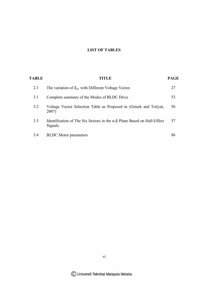
LIST OF TABLES
TABLE
2.1
3.1
3.2
3.3
3.4
TITLE
The variation of with Different Voltage Vector. Complete summary of the Modes of BLDC Drive Voltage Vector Selection Table as Proposed in (Ozturk and Toliyat, 2007) Identification of The Six Sectors in the α-β Plane Based on Hall-Effect Signals. BLDC Motor parameters
PAGE
27
53
56
57
86

vii
LIST OF FIGURES
FIGURE
1.1
1.2
1.3
1.4
2.1
2.2
2.3
2.4
2.5
2.6
2.7
2.8
2.9
2.10
3.1
TITLE
Control structure of basic DTC hysteresis based induction machine. Schematic diagram of Voltage Source Inverter (VSI). Voltage space vectors of a three phase inverter with the combination of switching states. Flowchart of the research. Schematic diagram of VSI. Voltage space vector. Six equally divided sectors of the stator flux plane.
Block diagram of the stator flux hysteresis comparator. Typical waveforms of the stator flux, the flux error and the flux error status for the two level hysteresis flux comparator. Two possible active voltage vector for each sector to control the stator flux within its hysteresis band. The variation of with application of (a) active voltage vector (b) zero or radial voltage vector, (c) reverse voltage vector. Three level torque hysteresis comparator. Typical waveforms of the torque, the torque error and the torque error status for three level hysteresis comparator. Four quadrants operation. Control Structure of hysteresis based DTC of BLDC Motor.
PAGE
5 6 7 9
22
23
24
25
25
26
28
29
31
33
40

viii
3.2
3.3
3.4
3.5
3.6
3.7
3.8
3.9
3.10
3.11
3.12
3.13
3.14
3.15
3.16
3.17
3.18
3.19
3.20
3.21
3.22
BLDC motor cross section and phase energizing sequence. Three phase DC to AC inverter. Three phase BLDC machine equivalent circuit and mechanical model. Ideal torque or back-emf voltage factor and current waveform for each phase (The output of Hall Effect sensors according to the rotor position are also given in the figure). BLDC mathematical model in laplace form. Schematic of a three phase BLDC motor connected to an inverter. Definition of voltage vector. Complete simulation of BLDC motor model. VSI in simulation. Torque hysteresis controller. DTC of BLDC motor drive block diagram. Torque and sector estimation block. Block diagram of the experimental setup. MATLAB simulation for the Experimental Setup. Laboratory experiment setup. DS1104 R&D controller board. Control desk configurations. Altera FPGA – Cyclone III DEO board. Block diagram of voltage vectors selection table and blanking time generation. Block diagram of blanking time generation for a single leg (i.e phase a). Gate driver schematic diagram.
43
44
45
49
50
51
55
65
67
68
70
71
73
74
75
77
79
80
81
81
83

ix
3.23
4.1
4.2
4.3
4.4
4.5
4.6
Schematic of the IGBT module with the capacitor snubbers. Simulation results of electromagnetic torque, d-axis voltage, q-axis voltage and sector ( constant torque of 0.7 N.m). Experimental results of electromagnetic torque, d-axis voltage, q-axis voltage and sector (constant torque of 0.7 N.m). Simulation results of electromagnetic torque, phase A current, phase B current and phase C current (for step of change of reference torque from -0.3 N.m to -1.2 N.m) Experimental results of electromagnetic torque, phase A current, phase B current and phase C current (for step of change of reference torque from -0.3 N.m to -1.2 N.m) Simulation results of electromagnetic torque, phase A current, phase B current and phase C current (for step of change of reference torque from 0.3 N.m to 1.2 N.m) Experimental results of electromagnetic torque, phase A current, phase B current and phase C current (for step of change of reference torque from 0.3 N.m to 1.2 N.m)
84
89
90
91
92
93
94

x
LIST OF APPENDICES
APPENDIX
A
B
C
TITLE
Machine Equations Details of MATLAB Simulation VHDL Code
PAGE
102
107
117

xi
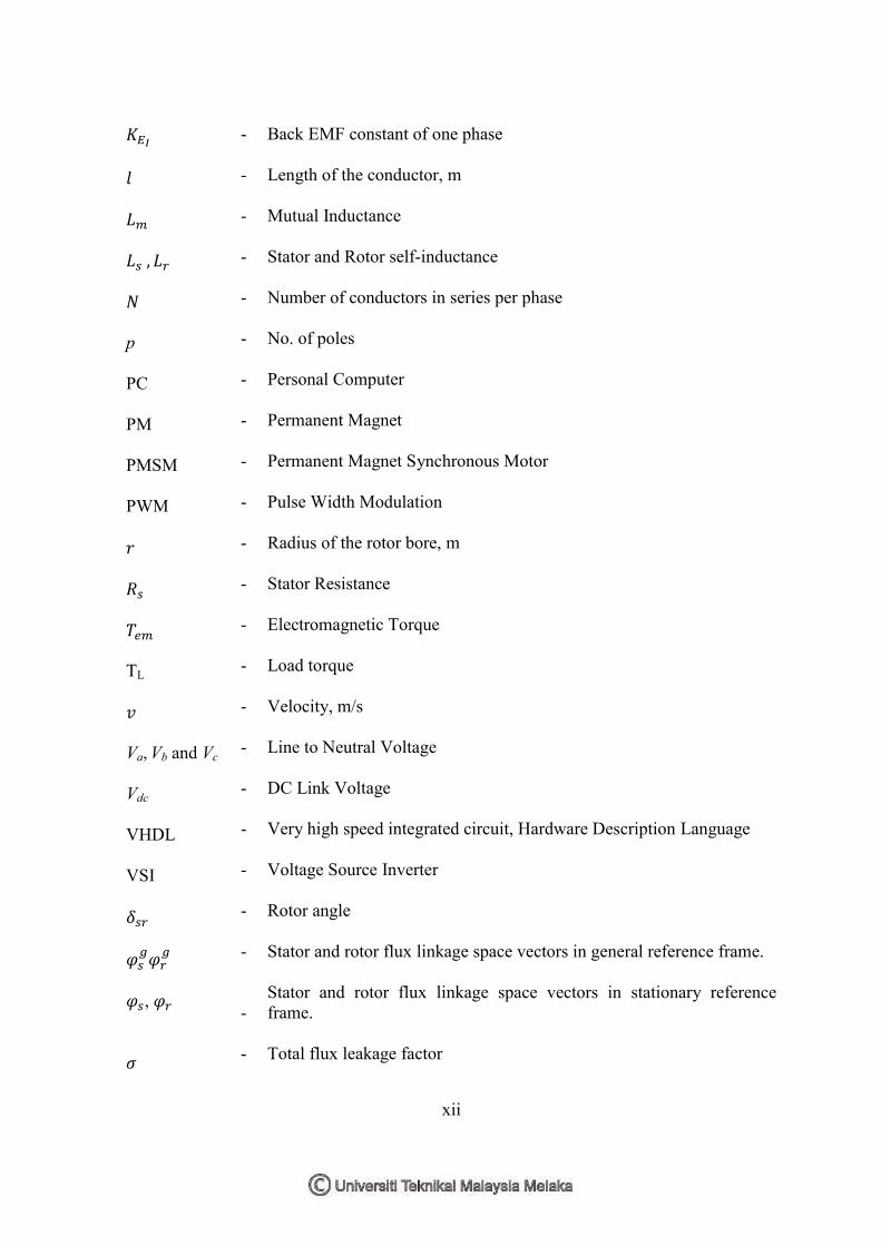
LIST OF SYMBOLS AND ABBREVIATIONS
ADC B BLDC CPLD DAC DSC DSP
DTC , EMF FOC FPGA ids & iqs IE IM J ,
- - - - - - - - - - - - - - - - - -
Analogue to Digital Converter Viscous friction Flux density of the field in which the conductors are placed Brushless DC Motor Complex Programmable Logic Device Digital to Analogue Converter Direct Self Control Digital Signal Processor Direct Torque Control Motor back EMF in stationary reference frame Electromotive Force Field Oriented Control Field Programmable Gate Array d and q components of the stator current in stationary reference frame Incremental Encoder Induction Machine Moment of Inertia Stationary reference frame back EMF constant according to electrical rotor position
xii
p PC PM PMSM PWM TL Va, Vb and Vc
Vdc VHDL VSI
,
- - - - - - - - - - - - - - - - - - - - - - -
Back EMF constant of one phase Length of the conductor, m Mutual Inductance Stator and Rotor self-inductance Number of conductors in series per phase No. of poles Personal Computer Permanent Magnet Permanent Magnet Synchronous Motor Pulse Width Modulation Radius of the rotor bore, m Stator Resistance Electromagnetic Torque Load torque Velocity, m/s Line to Neutral Voltage DC Link Voltage Very high speed integrated circuit, Hardware Description Language Voltage Source Inverter Rotor angle Stator and rotor flux linkage space vectors in general reference frame. Stator and rotor flux linkage space vectors in stationary reference frame. Total flux leakage factor

xiii
- - - - -
Electrical rotor angle Mechanical rotor angle Rotor speed Electrical rotor speed Rotor angular velocity, rad/s
xiv
LIST OF PUBLICATIONS
NO.
1 2 3
TITLE AHMAD FAIZ BIN NOOR AZAM , M. B. M., AUZANI BIN JIDIN , NORHAZILINA BINTI BAHARI, , HATTA BIN JOPRI, ABDUL RAHIM BIN ABDULLAH 2012. Torque Hysteresis Controller for Brusless DC Motor Drives. Power and Energy Conversion Symposium (PECS 2012). AZAM, A. F. N., JIDIN, A., NGATIMAN, N. A., JOPRI, M. H., MANAP, M., HERLINO, A. L. & ALIAS, N. F. 2013 Current control of BLDC drives for EV application. Power Engineering and Optimization Conference (PEOCO), 2013 IEEE 7th International, 3-4 June 2013. 411-416. NOOR AZAM, A. F., JIDIN, A., SAID, M. A., JOPRI, H. & MANAP, M. 2013. High performance torque control of BLDC motor. Electrical Machines and Systems (ICEMS), 2013 International Conference on, 26-29 Oct. 2013. 1093-1098.

1
CHAPTER 1
INTRODUCTION
1.0 Research Background
Conventional dc motors are highly efficient and their characteristic makes it
reliable for use in many applications. However, the only drawback is that it uses
commutator and brushes that require frequent maintenance and cannot be performed at
dirty and explosive environment and at very high speed operating conditions.
Maintenance-free motor can be developed by replacing the functions of commutator and
brushes by solid-state switches, and these types of motors are now known as Brushless DC
(BLDC) motors. BLDC motors are, in fact, a type of permanent magnet synchronous
motors (PMSM). It is driven by dc voltage, and the current commutations are done by
solid-state switches.
BLDC motor has advantages of longer lifespan, faster torque response and
capability of high speeds drive in comparison with DC motor (Jeon et al., 2000). BLDC
motor implements the basic operating principles of DC motor operation but with a
difference by placing the permanent magnet in the rotor and coils in the stator. The coil
windings are electrically separate from each other, which allow it to be turn on and off in a
sequence that creates a rotating magnetic field. The rotor position needs to be determined

2
so that excitation of the stator field always leads the permanent magnet field to produce
torque. The commutation instants are determined by the rotor position, and the position of
the rotor is detected either by position sensors or by sensorless techniques. The signals
from Hall Effect sensors that usually used in BLDC motor need to be decoded to determine
the shaft position and appropriate excitation of stator windings.
The three phase power electronic converter is necessary to operate the BLDC
machine. The converter converts DC to AC via six solid-state semiconductor switches.
MOSFET and IGBT are the most common types of switches being used. In lower power
application, MOSFET are preferred over IGBT. The power electronic inverter must be
capable of applying positive, negative and zero voltage across the motor phase terminals.
Each drive phase consists of one motor terminal driven high, one motor terminal driven
low, and one motor terminal floating.
1.1 Significance of Research
This research is based on the popularity of BLDC motor drives as mentioned
above, i.e. high-torque density, high-speed operations, free-maintenance, etc. The BLDC
motor drives require precise and robust control of torque, as well as current limiter to avoid
inrush current due to sudden large torque demand especially during acceleration modes.
Traditionally, the method of hysteresis torque/current controller was used to meet the
above requirements. However, this conventional method operates the inverter at three
phase conduction mode, in which produces high switching frequency as well as switching
losses. In addition, the three phase conduction mode in this method may degrade the
inverter switching reliability. The significance of the research is to minimize the problems,

3
i.e. switching frequency/losses by applying DTC method with two-phase conduction mode
as proposed in (Ozturk and Toliyat, 2007) for a BLDC motor. The DTC operation of two-
phase conduction mode is verified via simulation and experimental results.
1.2 Overview of Modern BLDC Motor Drives
Vector control and DTC drives are the two types of instantaneous electronic torque
controlled AC drives used for high-performance applications. The first vector control
which is called Field Oriented Control (FOC) was introduced more than 25 years ago in
Germany by Hasse, Blaschke (Blaschke, 1972). FOC transforms the motor equations into
a coordinate system that rotates in synchronism with the rotor flux vector. There is a linear
relationship between the control variables and the torque when operating under constant
rotor flux amplitude. FOC drives achieved a high degree of maturity and established in
worldwide markets.
DTC was introduced in Japan by Takahashi and Nagochi (Takahashi and Noguchi,
1986) and also in Germany by Depenbrock (Depenbrock, 1988). DTC is a method that
uses a bang-bang / hysteresis control instead of a decoupling control which symbolizes the
characteristic of a vector control. The hysteresis control technique works well with the on-
off operation of the switches (i.e MOSFET and IGBT). DTC controls the electromagnetic
torque and flux linkage directly and independently using six or eight voltage space vectors
as defined in the lookup table. Lookup table is constructed to choose appropriate switching
states of the inverter which the selection is based on the output of the hysteresis controller
and the sector of the stator flux vector in the circular trajectory.

4
DTC technique was first introduced in the late 1980’s to drive the induction
machine; however, the method has been absorbed to the other types of AC drives to
improve the existing results. Now researchers are focusing on combining the DTC
techniques with PMSM / BLDC machines, as reported in (Ozturk et al., 2010, Ozturk and
Toliyat, 2007, Ozturk and Toliyat, 2011, Rahman et al., 2004, Yong et al., 2005, Yong et
al., 2007, French and Acarnley, 1996, Lixin et al., 2003, Seog-Joo and Seung-Ki, 1995,
Sung Jun et al., 2000, Zhong et al., 1997, Zhu et al., 2005). DTC scheme for induction
machines still has a few drawbacks, which are the high torque and stator flux linkage
ripples, switching frequency that varies with load torque, rotor speed and the bandwidth of
the hysteresis controllers. Researchers have been working to reduce the torque and flux
ripple and fix the switching frequency of the DTC system as reported in (Buja et al.,
1997b, Buja et al., 1997a, Casadei et al., 1995, Jidin et al., 2011a, Jidin et al., 2011b, Jidin
et al., 2012, Takahashi and Noguchi, 1997). A modified DTC scheme with fixed switching
frequency and low torque and flux ripple was introduced in (Jidin et al., 2010).
For DTC of BLDC, the back EMF integration for the stator flux linkage calculation
requires the knowledge of stator flux position during start up. In order to find its position in
the circular trajectory it needs to be sensed by position sensor, but it is not desired due to
its cost and bulky characteristics; therefore, some initial position sensing methods are
required for DTC of BLDC applications. (Noguchi et al., 1998) proposed a method for
detecting the initial rotor position estimation at the standstill for PM motors. A better
solution was introduced for the rotor position estimation by applying high-frequency
voltage to the motor; this method is adopted in the DTC of BLDC motor for initial position
estimation in (Rahman et al., 2004).

5
1.3 Overview of Basic DTC
A simple control structure of basic DTC was introduced by Takahashi. The
structure consist a pair of hysteresis controllers, switching table / lookup table for voltage
vectors selection, a three phase voltage source inverter (VSI) and lastly flux and torque
estimators as shown in Figure 1.1. In DTC, torque and flux are controlled by satisfying
their demands simultaneously using appropriate voltage vector selection. Then the voltage
vector is used either to increase or decrease the torque and stator flux based on the criteria
of torque error status, flux error status and flux orientation.
Figure 1.1 Control structure of basic DTC hysteresis based induction machine.
The motor operating condition which includes the rotor speed, stator and rotor
fluxes and DC link voltage influence the torque and flux slope criteria hence affecting the
switching pattern of the hysteresis comparators. Furthermore, the switching frequency of
the VSI also gets affected by the operating conditions. A three phase VSI consists of six
switching devices (i.e IGBT, MOSFET, GTO, etc.) which transform the DC link voltage to
the AC voltage source. From Figure 1.2, it can be seen that the VSI is connected to a wye
Switching table or look up
table
+
IM
Sector
-
+
- Command flux, Ψ*
Estimate torque, Te Estimate flux,Ψs
Voltage source
inverter (VSI)
Stator flux and electromagnetic torque esimator (i.e. only using the voltage model)
ia,ib,ic
va,vb,vc
Sa, Sb, Sc Command Torque, Te*