faculty of engineering - near east university docsdocs.neu.edu.tr/library/4812709967.pdf · use...
TRANSCRIPT
Faculty of Engineering
Department of Electrical and Electronics Engineering
ELECTRICAL INSTALLATION AND ILLUMINATION DRAWING PROJECT
STUDENT: YAZEN AL SAHA WNEH
NUMBER: 20010901
COURSE: EE400
TEACHER: ASSIST.PROF.DR DOGAN HAKTANIR
Nicosia - 2006

ACKNOWLEDGMENTS
First and Foremost I would like to thank almighty ALLAH for giving me the strength and
sincereness during this Project.
My special Thanks to my Supervisor Ass.Prof Dr.DOGAN HAKTANJR,for his valuable
advice and outmost support in completing this Project.
Second, I would like to thank my family especially my father Fouzat AL Sahawneh and also
my uncle Ramzi AL Sahawneh for giving me the chance to complete my academic study and a
big thanks for the one who stay near me and support me during the preparation of this project
Nebile kimiziler
I

ABSTRACT
As whole world is trying to save energy for future or for coming rainy days, so
world is going toward finding out the to protect the electrical installation we have and
use alternative resources the practical part about layout the faculty of engineering, hold
three floors each of them has three distribution boxes expect the ground floor has four of
distributions. There are many different technologies used in circuit breakers and they do
not always fall into distinct categories. The following types are common used in our
plan domestic, commercial and light industrial applications for low voltage (less than
1 OOOV) use. MCB - Miniature Circuit Breaker - rated current not more than 1 OOA. Trip
characteristics normally not adjustable. Thermal or thermal-magnetic operation.
Breakers illustrated above are in this category. MCCB - Moulded Case Circuit Breaker -
rated current up to 1 OOOA. Thermal or thermal-magnetic operation. Trip current may be
adjustable.
When choosing a cable one of the most important factors is the temperature attained by
its insulation; if the temperature is allowed to exceed the upper design value, premature
failure is likely. In addition, corrosion of the sheaths or enclosures may result. For
example, P.V.C. becomes hard and brittle at low temperatures, and if a cable insulated
with it is installed at temperatures below 5°C it may well become damaged.
The earthing conductor is commonly called the earthing lead. It joins the installation
earthing terminal to the earth electrode or to the earth terminal provided by the
Electricity Supply Company, but great care must be taken when doing so to ensure that
there will be no problems with corrosion or with electrolytic action where they come
into contact with other metals.
Later on advantages and disadvantages are discussed briefly in this project.

TABLE OF CONTENTS ABTRACT ITABLE OF CONTENTS IILIST OF FIGURES IIILIST OF TABLES VI INTRODUCTION 1 CHAPTER ONE: CABLES, CONDUITS AND TRUNKING 3 1.1 - Cable insulation materials 4 1.2 - Cables 6
1.2.1 Cables for overhead lines 6 1.2.2 Flexible low voltage cables and cords 6 1.2.3 Corrosion 9
1.3 Cable choice 10 1.3.1 - Cables types 10 1.3.2 - Methods of cables installation 12 1.3.3 - Cable volt drop 13
1.4 - Cable supports, joints and terminations 15 1.4.1 - Cable supports and protection 15 1.4.2 - Cables joints and termination 16
1.5 - Conductor and cable identification 17 1.5.1 - Conduits 17 1.5.2 - Colours for flexible cables and cords 18 1.5.3 - Identification of fixed wiring conductors 18
CHAPTER TWO: INSTALLATION CONTROL AND 20 PROTECTION 2.1 - Introduction 20 2.2 - Switching 20
2.2.1 - Switch positions 20 2.2.2 - Emergency switching 22
2.3 - Isolation 26 2.3.1 - Isolator definition 26 2.3.2 - Semiconductor isolators 27 2.3.3 - Isolator identification 28
2.4 - High temperature protection 28 2.4.1 - Introduction 28 2.4.2 - Fire protection 29 2.4.3 - Protection from burns 31
2.5 - Overload currents 32 2.5.1 - Introduction 32 2.5.2 - Overload 33 2.5.3 - Fuses 35 2.5.4 - Circuit breakers 38
I

38 2.5.5 - Types of circuit breaker 2.5.6 - Protecting conductors - 42 2.5. 7 - Advantages of Circuit Breakers 47
48 2.5.8 - Fuses compared with circuit breakers
2.6 - Short circuit and overload protection 48 2.6.1 - Combined protection 48 2.6.2 - Current limited by supplied characteristic 49 2.6.3 - Protection omitted 49 2.6.4 - Protection of conductors in parallel 49 2.6.5 - Absence of protection 50 2.6.6 - Discrimination 51
CHAPTER THREE: BASIC REQUIREMENTS OF CIRCUITS 54 3.1 - Basic requirements of circuits 54
3.1.1 - Basic requirements of circuits 54 3.2 - Maximum demand and diversity 57
3.2.1 - Maximum demand 57 3.2.2 - Diversity 58
3.3 - BS1363 socket outlet circuits 60 3.3.1 - The fused plug 60 3.3.2 - The ring final circuit 63 3.3.3 - The radial circuit 64
3.4 - Industrial socket outlet circuits 66 3.4.1 - Introduction 66 3.4.2 - BS 196 socket outlet circuits 66 3.4.3 - BS EN 60309-1 (BS 4343) socket outlet circuits 68
3.5 - Circuit segregating 69 3.5.1 - Segregating circuits 69 3.5.2 - Electromagnetic compatibility 70 3.5.3 - lift or hoist shaft circuits 71
CHAPTER FOUR: THE EARTHING PRINCIPLE 73 4.1 - The earthing principle 73
4.1.1 - What is earthing? 73 4.1.2 - The advantages of earthing 74 4.1.3 - The disadvantages of earthing 75
4.2 - Earth fault loop impedance 76 4.2.1 - The importance of loop impedance 76 4.2.2 - Earth-fault loop impedance values 77 4.2.3 - Protective conductors impedance 82
4.3 - protective conductors 83 4.3.1-Earthing conductors 83 4.3.2 - Bonding conductors 84 4.3.3 - Unearthed metalwork 88
4.4 - earth electrodes 88
II

4.4.1 - Why we must have earth electrodes? 88 4.4.2 - Earth electrode types 88
4.5 - Earthed concentric wiring 90 4.5.1 - What is earth concentric wiring? 90 4.5.2 - Requirements for earthed concentric wiring 90
4.6 - Combined functional and protective earthing 91 CHAPTER FIVE: ELECTRICAL INSTALLATION SERIES 92 5.1 - Introduction 92
5.2 - Inverse Square Law 92 5.3 - Cosine Law 92
5.4 - Other Factors in Illumination 92
5.5 - Calculation 93
5.6 - Calculation the voltage drop 96 CONCLUSION 103 REFERENCES 105
III

LIST OF FIGURES Figure 1.1 - shows some of the many tyoes of flexible cords which are available Figure 1.la - Braided circular 7 Figure 1.lb- Unkinkable 7 Figure 1.lc - Circular sheathed 7 Figure 1.ld - Flat twin sheathed 8 Figure 1.le - Braided circular insulated with glass fibre 8 Figure 1.lf - Single core p.v.c. - insulated non-sheathed 8 Figure 1.2 - l 50°C rubber-insulated and braided flexible cord used 9
for the final connection to a luminaire Figure 1.3 - Insulation of a cable connected to hot busbar 11 Figure 1.4 - Total volt drop in large installations 15 Figure 1.5 - Spacing of support clips on angled runs 16 Figure 1.6 - Failure to enclose non-sheathed cables 17 Figure 1.7 - Care colours for flexible cables and cords 18 Figure 1.8 - identification of fixed wiring 19 Figure 2.1 - Supply system broken by switches 22 Figure 2.2 - Two circuit breakers linked to a common stop circuit. 24
The system is 'fail-safe' Figure 2.3 - 'latching-off stop button 25 Figure 2.4 - Speed control for a de motor fed from a three-phase supply 27 Figure 2.5 - Precautions for equipment which contains flammable liquid 30 Figure 2.6 - Time/current characteristics 35
a) 30 A semi-enclosed fuse b) 30 A miniature circuit breaker type 3Figure 2. 7 - Time/current characteristics of semi-enclosed fuses to BS 3036 36 Figure 2.8 - Time/current characteristics of cartridge fuses to BS 1361 37 Figure 2.9 - Time/current characteristics of cartridge fuses to BS 88 Part 2 40 Figure 2.1 O - Time/current characteristics for some miniature circuit breakers 43 Type l Figure 2.11 - Time/current characteristics for some miniature circuit breakers 44 TypeB Figure 2.12 - Time/current characteristics for some miniature circuit breakers 45 TypeD Figure 2.13- Position and rating of devices for overload protection 46 Figure 2.14 - Cables in parallel the lower resistance path will carry the higher 50 fault current Figure 2.15 - System layout to explain discrimination 51 Figure 2.16 - To illustrate a lack of discrimination 53 Figure 3.1 - Typical arrangement for feeding final circuits in a domestic 55 installation Figure 3.2 - An arrangement for main and final circuits in a large installation 56 Figure 3.3 - Plug and socket 61 Figure 3.4 - Principle of appliance protection by plug fuse 62 Figure 3.5 - Ring circuit feeding socket outlets 63 Figure 3.6 - Radial circuits 65 Figure 3. 7 - Arrangement of socket outlet 67
III

Two of the eighteen possible keyway positions are shown Figure 3.8 - Circuit fed from a transformer with a centre-tapped secondary 68 winding Figure 3.9 - Plugs and sockets 68 Figure 3.10- Cables installed in lift or hoist shafts 72 Figure 4.1 - Three-phase delta/star transformer showing earthing arrangements 74 Figure 4.2 - Path for earth fault current (shown by arrows) 75 Figure 4.3 - Danger in an unearthed system 76 Figure 4.4 - Measurement of protective conductor resistance 82 Figure 4.5 - Main bonding connections 84 Figure 4.6 - Supplementary bonding in a bathroom 86 Figure 4.7 - Supplementary bonding conductor in a kitchen 87 Figure 4.8 - Connection of earthing conductor to earth electrode 89 Figure 4.9 - Earth tail seal for use in earthed concentric wiring 90
m

LIST OF TABLES Table 1.1 - Maximum mass supported by twin flexible cord 8 Table 1.2 - Maximum spacing for cable supports 16 Table 2.1 - Allowable surface temperatures for accessible parts 32 Table 2.2 - Sizes of tinned copper wire fuse elements 38 Table 2.3 - Operating time ranges and current multiples for MCBs 41
over fixed current section of characteristic Table 2.4 -A comparison of types of protective device 42 Table 2.5 - Comparison of miniature circuit breaker types 42 Table 3.1 - Current demand of outlets 58 Table 3.2 - Proposed EMI cable separation distances 71 Table 4.1 - Maximum earth-fault loop impedance for 240 V socket outlet 79 circuits protected by fuses Table 4.2 - Maximum earth-fault loop impedance for 240 V circuit protected 79 by miniature circuit breakers to give compliance with 0.4 s disconnection time Table 4.3 - Maximum impedance of circuit protective conductors to allow 5 s 80 disconnection time for socket outlets Table 4.4 - Maximum earth-fault loop impedance for 240 V fixed equipment 81 distribution circuits protected by fuses Table 4.5 - Supplementary bonding conductor sizes 85 Table 5.1 - Current ratings and volt drops for unsheathed single core p.v.c. 98 insulated cables Table 5.2 - Current ratings and volt drops for sheathed multi-core p.v.c.- 98 insulated cables Table 5.3 - Current ratings of mineral insulated cables clipped direct 99 Table 5.4 - Volt drops for mineral insulated cables 99
VI

INTRODUCTION
These regulations (commonly called the I.E.E. Regulations) have been devised by the
wiring committee of the Institution of Electrical Engineers to "ensure safety in the
utilization of electricity in and about buildings". The I.E.E. Regulations are of
considerable assistance to electricians as they largely cover the requirements of the
Electricity Supply Regulations. The I.E.E. Regulations consist of two parts: part 1
contains "requirements for safety" and part 2 contains "means of securing compliance
with part l ".
It should be noted that the I.E.E. Regulations are not legally binding but are generally
accepted as an efficient standard by Electrical Boards, contractors and industrial and
domestic consumers. However, Electrical Boards may have their own particular rules
which must be obeyed particular industries have their own regulations for example, coal
mines and cinemas these special regulations have the force of law.
Generally, if an installation complies with the I.E.E. Regulations it complies both with
the Factory Acts and with the Electricity Supply Regulations since the I.E.E. Regulations
are based on the requirements of these statutory regulations.
The Grid is made up a series of power stations throughout the country which feed current
into a system of conductors at a very high voltage. Overhead conductors, supported by
steel towers, are used to carry the current over long distance.
There are three main types of power stations: (1) coal-fired (2) nuclear (3) hydro-electric.
The most common type is the coal-fired station. Heat, obtained from. The burning of
low-grade coal is used to produce high pressure steam. This high pressure steam is used
to drive the turbine which is mechanically connected to a 3-phase a.c. generator
generating at 11,000V. The voltage is stepped up, by means of a transformer, to
132,000V.
High voltages are used in order to transmit high power with a cable of small cross
sectional area and also to increase the efficiency of transmission by decreasing copper
losses.

The domestic ring circuit is defined as a final sub-circuit in which the current-carrying
and earth-continuity conductors are connected in the form of a loop, both ends of which
are connected to a single way in a distribution fuse board or its equivalent. A spur of ring
circuit shall be a branch cable having conductors of a cross-sectional area not smaller
than that of the conductors forming the ring.
Protection the temporary installation must be protected with an adequate switch which
isolates all the poles from the supply.
A cable type is determined by the specifications of the system installed, basic electronic
principles, and environment and regulatory agencies. These various
criteria dictate the type of conductor(s), gauge of wire, type of insulation, twisted or
cabled construction, type of jacket and if any shielding is required. A basic
understanding of cable construction should be helpful in selecting and installing the
proper cable for a particular system.
Conductors for electronic cables can vary greatly from stranded conductors for maximum
flexibility to copper covered steel which provides a stronger cable that will withstand a
greater physical strain than copper. The American Society For Testing and Materials
(ASTM) standards are followed for all of West Penn Wire conductor material. The
ASTM
standard defines standard requirements such as tensile strength, elongation, resistivity,
dimensions, permissible variations, finish, inspection, and testing.
There are several types of material that conduct electricity well (aluminum, nickel, gold,
silver). However, copper is the most popular due to its excellent conductivity compared
to other material cost. West Penn Wire uses a variety of conductors in our cable. Material
used can be bare copper, tinned copper, and copper covered steel. The conductor can
consist of solid or stranded construction. The type of conductor selected is determined by
the application the cable will be used for.
There are basically three types of shielding techniques: foil shielding, braid shielding,
and combination shielding. Shielding is utilized to prevent radiation and signal loss of
high frequencies used in electronic circuits and to reduce EMI/RFI interference.
However, shielding tends to increase the overall capacitance of the cable.
-- --- -- ~· -~ -- -·----

The resistance which a conductor offers to flows of current is determined by three
factors: (a) the length of the conductor, (b) its cross-sectional area and (c) type of material
used.
The circuit breaker is defined as a mechanical device for making and breaking a circuit
both under normal conditions and under abnormal conditions, such as those of a short
circuit, the circuit being broken automatically.
The circuit-breaker is generally opened and closed by hand (manually) but is
automatically opened under fault conditions by an over-current release. The over-current
release is operated by the magnetic effect of the line current flowing in the circuit. This
current flows through a current coil consisting of a few turns of heavy-gauge copper wire
or copper tape. When a continual overload is placed on the protected circuit the
electromagnetic field, due to the current flowing in the coil, draws up a plunger which
operates a mechanical trip, thus isolating the circuit from the supply.
Circuit breakers are available in a great variety of sizes and types. Army marine circuit
breakers are of the molded case, trip-free type. They must be arranged so that they can be
removed without disconnecting the copper or cable connections or de-energizing the
power supply to the circuit breaker. The circuit breaker rating should be the value of
current the breakers will carry continuously without exceeding the specific temperature
rise.
Applications. Over-current releases are commonly used in motor starter circuits where
very high starting currents (about six times the full load current) are encountered. The
time-lag action of the dashpot allows sudden surges of current in the circuit without
tripping, although a continuous overload current would operate the trip.
A fuse is defined as a device for opening a circuit by means of a conductor designed to
melt when an excessive current flows. The fuse comprises all the parts that form the
complete device.

CHAPTER ONE
Cables, conduits and trunking
1.1 - Cable insulation materials
Rubber For many years wiring cables were insulated with vulcanized natural rubber (VIR). Much cable of this type is still in service, although it is many years since it was last manufactured. Since the insulation is organic, it is subject to the normal ageing process, becoming hard and brittle. In this condition it will continue to give satisfactory service unless it is disturbed, when the rubber cracks and loses its insulating properties. It is advisable that wiring of this type which is still in service should be replaced by a more modem cable. Synthetic rubber compounds are used widely for insulation and sheathing of cables for flexible and for heavy duty applications. Many variations are possible, with conductor temperature ratings from 60°C to 180°C, as well as resistance to oil, ozone and ultra-violet radiation depending on the formulation.
Paper Dry paper is an excellent insulator but loses its insulating properties if it becomes wet. Dry paper is hygroscopic, that is, it absorbs moisture from the air. It must be sealed to ensure that there is no contact with the air. Because of this, paper insulated cables are sheathed, with impervious materials, lead being the most common. PILC (paper insulated lead covered) is traditionally used for heavy power work. The paper insulation is impregnated with oil or non-draining compound to improve its long-term performance. Cables of this kind need special jointing methods to ensure that the insulation remains sealed. This difficulty, as well as the weight of the cable, has led to the widespread use of p.v.c. and XLPE (thermosetting) insulated cables in place of paper insulated types.
P.V.C. Polyvinyl chloride (p.v.c.) is now the most usual low voltage cable insulation. It is clean to handle and is reasonably resistant to oils and other chemicals. When p.v.c. bums, it emits dense smoke and corrosive hydrogen chloride gas. The physical characteristics of the material change with temperature: when cold it becomes hard and difficult to strip, and so BS 7671 specifies that it should not be worked at temperatures below 5°C. However a special p.v.c. is available which remains flexible at temperatures down to - 20°c.
At high temperatures the material becomes soft so that conductors which are pressing on the insulation ( eg at bends) will 'migrate' through it, sometimes moving to the edge of the insulation. Because of this property the temperature of general purpose P.V.C. must not be allowed to exceed 70°C, although versions which will operate safely at temperatures up to 85°C are also available. If p.v.c. is exposed to sunlight it may be degraded by ultra-
1

violet radiation. If it is in contact with absorbent materials, the plasticizer may be 'leached out' making the p.v.c. hard and brittle.
LSF (Low smoke and fume) Materials which have reduced smoke and corrosive gas emissions in fire compared with p.v.c. have been available for some years. They are normally used as sheathing compounds over XLPE or LSF insulation, and can give considerable safety advantages in situations where numbers of people may have to be evacuated in the event of fire.
Thermosetting (XLPE) Gross-linked polyethylene (XLPE) is a thermosetting compound which has better electrical properties than p.v.c. and is therefore used for medium- and high-voltage applications. It has more resistance to deformation at higher temperatures than p.v.c., which it is gradually replacing. It is also replacing PILC in some applications. Thermosetting insulation may be used safely with conductor temperatures up to 90°C thus increasing the useful current rating, especially when ambient temperature is high. A LSF (low smoke and fume) type of thermosetting cable is available.
Mineral Provided that it is kept dry, a mineral insulation such as magnesium oxide is an excellent insulator. Since it is hygroscopic (it absorbs moisture from the air) this insulation is kept sealed within a copper sheath. The resulting cable is totally fireproof and will operate at temperatures ofup to 250°C. It is also entirely inorganic and thus non-ageing. These cables have small diameters compared with alternatives, great mechanical strength, are waterproof, resistant to radiation and electromagnetic pulses, are pliable and corrosion resistant. In cases where the copper sheath may corrode, the cable is used with an overall LSF covering, which reduces the temperature at which the cable may be allowed to operate. Since it is necessary to prevent the ingress of moisture, special seals are used to terminate cables. Special mineral-insulated cables with twisted cores to reduce the effect of electromagnetic interference are available.
1.2 - Cables
1.2.1 - Cables for overhead lines
Any of the cables listed in the previous subsection are permitted to be used as overhead conductors provided that they are properly supported. Normally, of course, the cables used will comply with a British Standard referring particularly to special cables for use as overhead lines. Such cables include those with an internal or external centenary wire, which is usually of steel and is intended to support the weight of the cable over the span concerned.
2

Since overhead cables are to be installed outdoors, they must be chosen and installed so as to offset the problems of corrosion. Since such cables will usually be in tension, their supports must not damage the cable or its insulation.
1.2.2 - Flexible low voltage cables and cords
By definition flexible cables have conductors of cross-sectional area 4 mm2 or greater, whilst flexible cords are sized at 4 mm2 or smaller. Quite clearly, the electrician is nearly always concerned with flexible cords rather than flexible cables.
{Figure 1.1} shows some of the many types of flexible cords which are available.
a) Braided circular - Fig 1.la
---- -
ı3
: 1 - oversheath- PVC14 - insulation- pvc coloured
ız~raid - plaincopperwire--~---15-Conductors-plainCopper - -I - -- -- --· --- - - - - - - - -- -
I 3 - innersheath- pvc
b) Unkinkable - Fig 1.lb
3

- - - --·---
3 z
' 1 - rubber layer collectively textileI braided semi-embeddedr---J2 - insulation (Cores) 60°C rubber ıI
i~_ _ t I\ 3 - conductors - tinned copper J
c) Circular sheathed - Fig 1.lc
I 1
1 - sheath - rubber or pvc'7f3I - ... [ = Iı= I 12 - insulation 60°C rubber or pvc3 :2 1
---I 3 - conductors - tinned copperI
d) Flat twin sheathed - Fig Ll d
--------------------r--- ---------- - --' 1 - sheath - PVCIII 2 - insulation - pvcI\ 3 - conductors - plain copper
------'
e) Braided circular insulated with glassfiber - Fig 1.le
- - -- --- ------ - ---·- -- ı---- - --
1 - glass braided overall
Iı 2 - insulation - silicon rubberI
\3~ conductors - strand~ Co~per
4

f) Single core p.v.c, - insulated non-sheathed - Fig 1.lf
,·-I l J 1 - insulation - pvc
2 ~ Iil~ 2---c-o-nd-uctors- ~;in copper
Flexible cables should not normally be used for fixed wiring, but if they are, they must be visiblethroughout their length. The maximum mass which can be supported by each flexible cord islisted in (Table 4H3A), part of which is shown here as (Table 1.1 ).
- -- . ------- -- - ·-·--: Table 1.1 - Maximum mass supported by twin flexible cordr---. Cross-sectional area (mmj)
Maximum mass to be supported(kg)
r --·- . -- . -· ---- - -I 0.5 I 2 -- - -- -1Ir - ,----
I 0.75 I 3
ı 1.0,- ------- - -i 5
r - - ---·- --, - ---- -
1.25 5I
[ 1.5 I 5
The temperature at the cord entry to luminaries is often very high, especially where filamentlamps are used. It is important that the cable or flexible cord used for final entry is of a suitableheat resisting type, such as 150°C rubber- insulated and braided. (Fig 1.2) shows a short lengthof such cord used to make the final connection to a luminaries.
5

-- - - ---·----- ---- - - ---
--- ------------Fig 1.2 -150°C rubber-insulated and braided flexible cord used
for the final connection to a luminaire
1.2.3 - Corrosion
The metal sheaths and armour of cables, metal conduit and conduit fittings, metaltrunking and ducting, as well as the fixings of all these items, are likely to suffercorrosion in damp situations due to chemical or electrolytic attack by certain
materials, unless special precautions are taken. The offending materials include:
1. - unpainted lime, cement and plaster,
2. - floors and dados including magnesium chloride,
3. - acidic woods, such as oak,
4. - plaster undercoats containing corrosive salts,
5. - dissimilar metals which will set up electrolytic action.
In all cases the solution to the problem of corrosion is to separate the materials betweenwhich the corrosion occurs. For chemical attack, this means having suitable coatings onthe item to be installed, such as galvanizing or an enamel or plastic coating. Bare coppersheathed cable, such as mineral insulated types, should not be laid in contact withgalvanized material like a cable tray if conditions are likely to be damp. A p.v.c. coveringon the cable will prevent a possible corrosion problem.
6
To prevent electrolytic corrosion, which is particularly common with aluminum-sheathedcables or conduit, a careful choice of the fixings with which the aluminum comes intocontact is important, especially in damp situations. Suitable materials are aluminum,alloys of aluminum which are corrosion resistant, zinc alloys complying with BS 1004,porcelain, plastics, or galvanized or sheradised iron or steel.
1.3 - Cable choice
1.3.1 - Cables types
When choosing a cable one of the most important factors is the temperature attained byits insulation; if the temperature is allowed to exceed the upper design value, prematurefailure is likely. In addition, corrosion of the sheaths or enclosures may result. Forexample, bare conductors such as busbars may be operated at much higher temperaturesthan most insulated conductors.
However, when an insulated conductor is connected to such a high temperature system,its own insulation may be affected by heat transmitted from the busbar, usually byconduction and by radiation. To ensure that the insulation is not damaged:
either the operating temperature of the busbar must not exceed the safe temperature forthe insulation,
or the conductor insulation must be removed for a suitable distance from the connectionwith the busbar and replaced with beat resistant insulation.
It is common sense that the cable chosen should be suitable for its purpose and for thesurroundings in which it will operate. It should not be handled and installed in unsuitabletemperatures. P.V.C. becomes hard and brittle at low temperatures, and if a cableinsulated with it is installed at temperatures below 5°C it may well become damaged.
[522] includes a series ofRegulations which are intended to ensure that suitable cablesare chosen to prevent damage from temperature levels, moisture, dust and dirt, pollution,vibration, mechanical stress, plant growths, animals, sunlight or the kind of building inwhich they are installed. Cables must not produce, spread, or sustain fire.
[527-01] contains six regulations which are intended to reduce the risk of the spread offire and are concerned with choosing cables with a low likelihood of flame propagation(see BS 4066, BS 476, BS EN 50085 and BS EN 50086). A run of bunched cables is aspecial fire risk and cables in such a situation should comply with the standards statedabove.
7

insulıtion r~movedand repla<:ed by ~ghteml)l'rah.ıre tape
r
iMUta.tion rated aıt lıeastto busbar tempera.bl~
Fig 1.3 Insulation of a cable connected to hot busbar
BS 6387 covers cables which must be able to continue to operate in a fire. These specialcables are intended to be used when it is required to maintain circuit integrity for longerthan is possible with normal cables. Such cables are categorized with three letters. Thefirst indicates the resistance to fire alone (A,B,C and S) and the second letter is a Wandindicates that the cable will survive for a time at 650°C when also subject to water (whichmay be used to tackle the fire). The third letter (X, Y or Z) indicates the resistance to firewith mechanical shock. For full details of these special cables see the BS.
1.3.2 - Methods of cables installation
We have seen that the rating of a cable depends on its ability to lose the heat produced init by the current it carries and this depends to some extent on the way the cable isinstalled. A cable clipped to a surface will more easily be able to dissipate heat than asimilar cable which is installed with others in a conduit,
Lists twenty standard methods of installation, each of them taken into account in therating tables of the same Appendix. For example, two 2.5 mm2 single core p.v.c.insulated non-armored cables drawn into a steel conduit (installation method 3) have acurrent rating of 24 A 2.5 mm2 twin p.v.c. insulated and sheathed cable, which containsexactly the same conductors, has a current rating of27 A when clipped directly to anonmetallic surface. Cables sheathed in p.v.c. must not be subjected to direct sunlight,because the ultra-violet component will leach out the plasticizer, causing the sheath toharden and crack. Cables must not be run in the same enclosure (e.g. trunking, pipe orducting) as non-electrical services such as water, gas, air, etc. unless it has beenestablished that the electrical system can suffer no harm as a result. If electrical and otherservices have metal sheaths and are touching, they must be bonded. Cables must not berun in positions where they may suffer or cause damage or interference with othersystems. They should not, for example, be run alongside hot pipes or share a space with ahearing induction loop.
8

Special precautions may need to be taken where cables or equipment are subject toionizing radiation. Where a wiring system penetrates a load bearing part of a buildingconstruction it must he ensured that the penetration will not adversely affect the integrityof the construction.
The build-up of dust on cables can act as thermal insulation. In some circumstances thedust may be flammable or even explosive. Design cable runs to minimize dustaccumulation: run cables on vertically mounted cable ladders rather than horizontal cabletrays. When cables are run together, each sets up a magnetic field with a strengthdepending on the current carried. This field surrounds other cables, so that there is thesituation of current-carrying conductors situated in a magnetic field. This will result in aforce on the conductor, which is usually negligible under normal conditions but whichcan become very high indeed when heavy currents flow under fault conditions. All cablesand conductors must be properly fixed or supported to prevent damage to them underthese conditions.
1.3.3 - Cable volt drop
All cables have resistance, and when current flows in them this results in a volt drop.Hence, the voltage at the load is lower than the supply voltage by the amount of this voltdrop.
The volt drop may be calculated using thebasic Ohm's law formula
U=IxR--------
'1 where I U is the cable volt drop (V-, -- ·- -- - -,
ı I is the! circuit current (A), and
r R is the circuit resistance JI
I O(Ohms)
9

Unfortunately, this simple formula is seldom of use in this case, because the cableresistance under load conditions is not easy to calculate.
[525-01-03] indicates that the voltage at any load must never fall so low as to impair thesafe working of that load, or fall below the level indicated by the relevant BritishStandard where one applies.
[525-01-02] indicates that these requirements will he met if the voltage drop does notexceed 4% of the declared supply voltage. If the supply is single-phase at the usual levelof240 V, this means a maximum volt drop of 4% of240 V which is 9.6 V, giving (insimple terms) a load voltage as low as 230.4 V. For a 415 V three-phase system,allowable volt drop will be 16.6 V with a line load voltage as low as 398.4 V.
It should be borne in mind that European Agreement RD 472 S2 allows the declaredsupply voltage of 230 V to vary by + 10% or -6%. Assuming that the supply voltage of240 V is 6% low, and allowing a 4% volt drop, this gives permissible load voltages of216.6 V for a single-phase supply, or 374.5 V (line) for a 415 V three-phase supply.
To calculate the volt drop for a particular cable , Each current rating table has anassociated volt drop column or table. For example, multicore sheathed non-armoredP.V.C. insulated cables are covered by for current ratings, and volt drops. The exceptionin the Regulations to this layout is for mineral insulated cables where there are separatevolt drop tables for single- and three-phase operation.
Each cable rating in the Tables of [Appendix 4] has a corresponding volt drop figure inmillivolts per ampere per meter of run (mV/A/m). Strictly this should be mV/(A m), buthere we shall follow the pattern adopted by BS 7671: 1992. To calculate the cable voltdrop:
1- take the value from the volt drop table (mV/A/m)2- multiply by the actual current in the cable (NOT the current rating)3- multiply by the length of run in meters4- divide the result by one thousand (to convert millivolts to volts).
The 'length of run' calculations carried out in these examples are often useful to theelectrician when installing equipment at greater distances from the mains position.
It is important to appreciate that the allowable volt drop of 4% of the supply voltageapplies to the whole of an installation. If an installation has mains, sub-mains and finalcircuits, for instance.
All of our work in this sub-section so far has assumed that cable resistance is the onlyfactor responsible for volt drop. In fact, larger cables have significant self inductance aswell as resistance. There is also an effect called impedance which is made up ofresistance and inductive reactance.
10

Inductive reactance XL
where XL =
(pi)
f
L
2(pi)fLinductive reactance in Dohmsthe mathematical constant 3.142
the system frequency in hertz (Hz)circuit self inductance in henrys(H)
It is clear that inductive reactance increases with frequency, and for this reason the voltdrop tables apply only to systems with a frequency lying between 49 Hz and 61 Hz.
'JV
4.5 V dro 406,V41SV 413.5 V
1.5 V drop ,--...• 250 A a;t.,(.).0060
100 A at, ·0 ..045Q
J v drop-.30 Aat0.1 Q load
supply intak
Fig 1.4Total volt drop in large installations
For small cables, the self inductance is such that the inductive reactance, is smallcompared with the resistance. Only with cables of cross-sectional area 25 mm2 andgreater need reactance be considered. Since cables as large as this are seldom used onwork which has not been designed by a qualified engineer, the subject of reactive voltdrop component will not be further considered here.
If the actual current carried by the cable (the design current) is less than the rated value,the cable will not become as warm as the calculations used to produce the volt drop tableshave assumed, The Regulations include (in [Appendix 4]) a very complicated formula tobe applied to cables of cross-sectional area 16 mm2 and less which may show that theactual volt drop is less than that obtained from the tables. This possibility is again seldomof interest to the electrician, and is not considered here.
1.4 - Cable supports, joints and terminations
1.4.1 - Cable supports and protection
Cables must be fixed securely at intervals which are close enough to ensure that therewill be no excessive strain on the cable or on its joints and terminations, and to prevent
11

cable loops appearing which could lead to mechanical damage. {Table 1.2} indicatesminimum acceptable spacings of fixings for some common types of cables.
Table 1.2 Maximum spacing for cable supports
Overall cable p.v.c. sheathed Mineral insulated
diameter Horizontal Vertical Horizontal Vertical
(mm) (mm) (mm) (mm) (mm)
upto 9 250 400 600 800
10 to 15 300 400 900 1200
16 to 20 350 450 1500 2000
21 to 40 400 550 2000 3000
Where cable runs are neither vertical nor horizontal, the spacing depends on the angle asshown in {Fig 1.5}.
Where a cable is flat in cross-section as in the case of a p.v.c. insulated and sheathedtype.
'/~. ..
spacings as forvertical runs
Fig 1.5 Spacing of support clips on angled runs
12

1.4.2 - Cables joints and termination
The normal installation has many joints, and it follows that these must all remain safe andeffective throughout the life of the system. With this in mind, regulations on jointsinclude the following:
1.-Alljoints must be durable, adequate for their purpose, and mechanically strong.
2.-They must be constructed to take account of the conductor material and insulation, aswell as temperature: eg, a soldered joint must not be used where the temperature maycause the solder to melt or to weaken. Very large expansion forces are not uncommon interminal boxes situated at the end of straight runs of large cables when subjected tooverload or to fault currents.
3. - All joints and connections must be made in an enclosure complying with theappropriate British Standard.
4. - Where sheathed cables are used, the sheath must be continuous into the jointenclosure.
5.-All joints must be accessible for inspection and testing unless they are buried incompound or encapsulated, are between the cold tail and element of a heater such as apipe tracer or underfloor heating system, or are made by soldering, welding, brazing orcompression.
la) trnnking not completeI
b) sheath not teken into joint box
Fig 1.6 Failure to enclose non-sheathed cables
13

1.5 - Conductor and cable identification
1.5.1 - Conduits
The 'electrical' colour to distinguish conduits from pipelines of other services is orange(BS 171 O). Oversheaths for mineral insulated cables are often the same colour, which isalso used to identify trunking and switchgear enclosures.
1.5.2 - Colours for flexible cables and cords
Unlike the cores of fixed cables, which may be identified by sleeves or tapes where theyare connected, flexibles must be identified throughout their length. The colourrequirements are shown in {Fig 1.7}.
~~~~~--.~~~~.-~~ ~~-
eutrnl blue ph~hıownneutral blue
---- _j
Fig 1.7 Care colours for flexible cables and cords
1.5.3 - Identification of fixed wiring conductors
Colour is used to identify the conductors of a wiring system where it is possible to colourthe insulation. Where it is not, numbers are used. The requirements for identification offixed wiring are shown in {Fig 1.8}. There is as yet no requirement to use brown andblue to identify the phase and neutral conductors of fixed wiring, although this applies toflexible cords and cables. The colour green on its own is prohibited, although green andyellow stripes identify the protective conductor. The functional earth conductor fortelecommunication circuits is identified by the colour cream.
14

,·----·cables insııılated with
nı'bbero,1ı;>ııçor EPRor XLPE
. mineralinsulation
· paperor!PR ,pr XLPE
prol.1.!tli11IJ
greeo/~•ellow
ph~se ,w ı·· rıt,ultal blue. yellow. ~bl.ıclı .._.,,_.ph.ı-şpetr.ı! ı;ondı,ıçl(Jf'Ş ·
Fig 1.8 Identification of fixed wiring
Some cables comply with HD 324:1977 and have blue insulation on the neutralconductor. This colour does not comply with BS 7671 and if such cables are used, theymust be correctly identified at their terminations by the use of black cable markers orblack tape.
15

CHAPTER TWO
Installation control and protection
2.1 - Introduction
Electrical installations must be protected from the effects of short circuit and over-load.In addition, the people using the installations, as well as the buildings containing them,must be protected from the effects of fire and of other hazards arising from faults or frommısuse.
This Chapter will consider those regulations which deal with the disconnection ofcircuits, by both manual and automatic means, the latter in the event of shock, shortcircuit or overload. It does not include the Regulations which concern automaticdisconnection in the event of an earth fault.
Not only must automatic fault protection ofthis kind be provided, but an installation mustalso have switching and isolation which can be used to control it in normal operation, inthe event of emergency, and when maintenance is necessary.
16
In order that anyone operating or testing the installation has full information concerningit, a diagram or chart must be provided at the mains position showing the number ofpoints and the size and type of cables for each circuit, the method of providing protectionfrom direct contact and details of any circuit in which there is equipment, such as passiveinfra-red detectors or electronic fluorescent starters, vulnerable to the high voltage usedfor insulation testing.
2.2 - Switching
2.2.1 - Switch positions
A switch is defined as a device which is capable of making or breaking a circuit undernormal and under overload conditions. It can make, but will not necessarily break, a shortcircuit, which should be broken by the overload protecting fuse or circuit breaker. Aswitching device may be marked with ON and OFF positions, or increasingly, thenumbers 1 for ON and O for OFF are being used.
A semiconductor device is often used for switching some lighting and heating circuits,but will not be suitable for disconnecting overloads; thus, it must be backed up by amechanical switch. The semiconductor is a functional switch but must NOT be used as anisolator.
{Figure 2.1} shows which poles of the supply need to be broken by the controllingswitches. For the TN-S system (earth terminal provided by the Electricity Company), theTNC-S system (protective multiple earthling) and the TT system (no earth provided at the

supply), all phase conductors MUST be switched, but NOT the protective (earth)conductor.
The neutral conductor need not be broken except for:1 - the main switch in a single-phase installation2 - heating appliances where the element can be touched3 - autotransformers (not exceeding 1.5 kV) feeding discharge lamps
The neutral will need to he disconnected for periodic testing, and provision must be madefor this; it is important that the means of disconnection is accessible and can only becompleted with the use of a tool.
The protective conductor should never be switched, except when the supply can he takenfrom either of two sources with earth Systems which must slot is connected together. Inthis case the switches needed in the protective conductors must be linked to the phaseswitches so that it is impossible for the supply to be provided unless the earthlingconnection is present.
Fig 2.1 Supply system broken by switches
combined earthand ooııl:fal (Pl;N)
imtallation
" V _,~ıııpply
(a) TN•C s~tem
' '
I I 1~\1\ ı,
l l lR Y 18
I I 1 I~~ijI I l ı
but
spe<;ial load~
t·~
~l I
installation, A,,___ .,., , I\ •••
V.:$YJliP-l'.1"
~l TN·S, TN·C·S
VsıJppty
(c) TI s~tffl'I
--------------- -- -- --
(a)TN-C Systems (b) TN-S, TN-C-S (c) TT Systems
Every circuit must be provided with a switching system so that it can be interrupted onload. In practice, this does not mean a switch controlling each separate circuit; providedthat loads are controlled by switches, a number of circuits may be under the overallcontrol of one main switch. An example is the consumer unit used in the typical house,where there is usually only one main switch to control all the circuits, which are providedwith individual switches to operate separate lights, heaters, and so on. If an installation issupplied from more than one source there must he a separate main switch for each source,and each must be clearly marked to warn the person switching off the supplies that morethan one switch needs to he operated.
17

It should he noted that a residual current device (RCD) may be used as a switch providedthat its rated breaking capacity is high enough.
2.2.2 - Emergency switching
Emergency switching is defined as rapidly cutting the supply to remove hazards. Forexample, if someone is in the process of receiving an electric shock, the first action of arescuer should he to remove the supply by operating the emergency switch, which maywell be the main switch. Such switching must be available for all installations. Note thatif there is more than one source of supply a number of main switches may need to beopened . The designer must identify all possible dangers, including electric shock,mechanical movement, excessive heat or cold and radiation dangers, such as those fromlasers or X-rays.
In the special case of electric motors, the emergency switching must be adjacent to themotor. In practice, such switching may take the form of a starter fitted close to the motor,or an adjacent stop button (within 2 m) where the starter is remote. Where a starter orcontactor is used as an emergency switch, a positive means must be employed to makesure that the installation is safe. For example, operation should be when the operating coilis de-energized, so that an open circuit in the coil or in its operating circuit will cause thesystem to be switched off {Fig 2.2}. This is often called the 'fail-safe' system.
18

n-}~il ıı
corıtarnoormaUy~
:1· I ··. tl=a~üOP_ T .JU~
stop circuit ~(common) stop ştop
oOo ooo~.~~--ıı--~~~
Fig 2.2- Two circuit breakers linked to a common stop circuit.The system is 'fail-safe'
To prevent unexpected restarting of rotating machines, the 'latching off stop buttonshown in {Fig 2.2} is sometimes used. On operation, the button locks (latches) in the offposition until a positive action is taken to release it.
In single-phase systems, it must he remembered that the neutral is earthed. This meansthat if the stop buttons are connected directly to the neutral, a single earth fault on thestop button circuit would leave the operating coil permanently fed and prevent the safetysystem from being effective. It is thus essential for the operating coil to be directlyconnected to the neutral, and the stop buttons to the phase. Such an earth fault would thenoperate the protective device and make the system safe.
The means of emergency switching must be such that a single direct action is required tooperate it. The switch must be readily accessible and clearly marked in a way that will bedurable. Consideration must be given to the intended use of the premises in which theswitch is installed to make sure as far as possible that the switching system is always easyto reach and to use. For example, the switch should not be situated at the back of a
19

cupboard which, in use, is likely to be filled with materials making it impossible to reachthe switch.
In cases where operation could cause danger to other people (an example is wherelighting is switched off by operating the emergency switch), the switch must be availableonly for operation by instructed persons. Every fixed or stationary appliance must beprovided with a means of switching which can be used in an emergency. If the device issupplied by an unswitched plug and socket, withdrawal of the plug is NOT acceptable tocomply with this requirement,' such action is acceptable for functional switching.
cıooeo
!
/sıapı:uıı:o1 /
conı.ıc-ı- -- - -- -- --- ---- ------- -
Fig 2.3 'Iatching-off stop button
Where any circuit operates at a p.d. (potential difference) exceeding low voltage afireman's emergency switch must be provided. Such installations usually take the form ofdischarge lighting (neon signs), and this requirement applies for all external systems aswell as internal signs which operate unattended. The purpose is to ensure the safety offire fighters who may, if a higher voltage system is still energized, receive dangerousshocks when they play a water jet onto it. The fireman's switch is not required forportable signs consuming 100 W or less which are supplied via an easily accessible plug
and socket.
The fireman's switch must meet the following requirements
1.-The switch must be mounted in a conspicuous position not more than 2.75m from the
ground.
2.-It must be coloured red and have a label in lettering at least 13 mm high 'FIREMAN'SSWITCH'. On and off positions should be clearly marked, and the OFF position shouldbe at the top. A lock or catch should be provided to prevent accidental reclosure.
3.-For exterior installations the switch should be close to the load, or to a notice in such aposition to indicate clearly the position of the well-identified switch.
4.-For interior installations, the switch should be at the main entrance to the building.
20

5.-Ideally, no more than one internal and one external switch must be provided. Wheremore become necessary, each switch must be clearly marked to indicate exactly whichparts of the installation it controls.
6.-Where the local fire authority has additional requirements, these must be followed.
7.-The switch should be arranged on the supply side of the step-up sign transformer.
2.3 - Isolation
2.3.1 - Isolator definition
An isolator is not the same as a switch. It should only be opened when not carryingcurrent, and has the purpose of ensuring that a circuit cannot become live whilst it is outof service for maintenance or cleaning. The isolator must break all live supplyconductors; thus both phase and neutral conductors must be isolated. It must, however, beremembered that switching off for mechanical maintenance is likely to be carried out bynon-electrically skilled persons and that they may therefore unwisely use isolators as onload switches. To prevent an isolator, which is part of a circuit where a circuit breaker isused for switching, from being used to break load current, it must be interlocked toensure operation only after the circuit breaker is already open. In many cases an isolatorcan be used to make safe a particular piece of apparatus whilst those around it are stilloperating normally.
2.3.2 - Semiconductor isolators
Semiconductors are very widely used in electrical installations, from simple domesticlight dimmers (usually using triacs) to complex speed controllers for three phase motors(using thyristors). Whilst the semiconductors themselves are functional switches,operating very rapidly to control the circuit voltage, they must NOT be used as isolators.
This is because when not conducting (in the OFF position) they still allow a very smallleakage current to flow, and have not totally isolated the circuit they control. {Figure 3.5}shows semiconductors in a typical speed control circuit.
21

trigger cirouit togive speed eentrel
I_J
Fig 2.4 - Speed control for a de motor fed from a three-phase supply
2.3.3 - Isolator identification
The OFF position on all isolators must be clearly marked and should not be indicateduntil the contacts have opened to their full extent to give reliable isolation. Every isolatormust be clearly and durably marked to indicate the circuit or equipment it protects. If asingle isolator will not cut off the supply from internal parts of an enclosure, it must belabelled to draw attention to the possible danger. Where the unit concerned is suitableonly for off-load isolation, this should be clearly indicated by marking the isolator "DoNOT open under load".
22

2.4 - High temperature protection
2.4.1 - Introduction
The Regulations are intended to prevent both fires and burns which arise from electricalcauses. Equipment must be selected and installed with the prevention of fire and burnsfully considered. Section 421, added in the 1994 amendments, require that persons,equipment and materials adjacent to electrical equipment must be protected from fire,burns and effects limiting the safe functioning of equipment. Three categories of thermalhazard are associated with an electrical installation.
1.-ignition arising directly from the installation,2.-the spread of fire along cable runs or through trunking where proper fire stops have notbeen provided, and3.-burns from electrical equipment.
The heat from direct sunlight will add significantly to the temperature of cables, and20°C must be added to the ambient temperature when derating a cable subject to directsunlight, unless it is permanently shaded in a way which does not reduce ventilation.Account must also be taken of the effect of the ultra-violet content of sunlight on thesheath and insulation of some types of cable.
Some types of electrical equipment are intended to become hot in normal service, andspecial attention is needed in these cases. For example, electric surface heating systemsmust comply fully with all three parts of BS 6351. Part 1 concerns the manufacture anddesign of the equipment itself, Part 2 with the design of the system in which it is used,and Part 3 its installation, maintenance and testing.
2.4.2 - Fire protection
Where an electrical installation or a piece of equipment which is part of it is, undernormal circumstances, likely to become hot enough to set fire to material close to it, itmust be enclosed in heat and fire resistant material which will prevent danger. Because ofthe complexity of the subject, the Regulations give no specific guidance concerningmaterials or clearance dimensions. It is left to the designer to take account of thecircumstances arising in a particular situation. When fixed equipment is chosen by theinstallation user or by some other party than the designer or the installer, the latter arestill responsible for ensuring that the installation requirements of the manufacturers aremet.
The same general principle applies in cases where an equipment may emit arcs or hotparticles under fault conditions, including arc welding sets. Whilst it may be impossiblein every case to prevent the outbreak of fire, attention must be paid to the means ofpreventing its spread.
For example, any equipment which contains more than 25 liters of flammable
23

o.r
app.ırdu's c.ont&ini~morethan 25 littn of Oil
""_ı; - ;L.
venöı.tion toi out$ide onlyI/iA'
door with siMto contain~ille-4 Oi1 -.....,.
' !I'
Fig 2.5 Precautions for equipment which contains flammable liquid
Liquid, must be so positioned and installed that burning liquid cannot escape the vicinityof the equipment and thus spread fire. {Figure 1.5} indicates the enclosure needed forsuch a piece of equipment, for example an oil-filled transformer. In situations where fireor smoke could cause particular hazards, consideration should be given to the use of lowsmoke and fire (LSF) cables. Such cables include those with thermosetting insulation andmineral-insulated types.
Perhaps a word is needed here concerning the use of the word 'flammable'. It meanssomething which can catch fire and bum. We still see the word inflammable in everydayuse, with the same meaning as flammable. This is very confusing, because the prefix 'in'may be taken as meaning 'not', giving exactly the opposite meaning. 'Inflammable' shouldnever be used, 'non-flammable' being the correct term for something which cannot catchfire.
Under some conditions, especially where a heavy current is broken, the current maycontinue to flow through the air in the form of an arc. This is more likely if the airconcerned is polluted with dust, smoke, etc. The arc will be extremely hot and is likely tocause bums to both equipment and to people; metal melted by the arc may be emittedfrom it in the form of extremely hot particles which will themselves cause fires and burnsunless precautions are taken. Special materials which are capable ofwithstanding sucharc damage are available and must be used to screen and protect surroundings from thearc.
Some types of electrical equipment, notably spotlights and halogen heaters, projectconsiderable radiant heat. The installer must consider the materials which are subject tothis heat to ensure that fire will not occur. Enclosures of electrical equipment must be
24

suitably heat-resisting. Recessed or semi-recessed luminaries mounted in ceiling voidsmust be given special attention to ensure the heat they produce cannot result in fire.Equipment that focuses heat, such as radiant heaters and some luminaries, must bemounted so that excessive temperatures are not reached in adjacent surfaces, theinstallation of a protecting RCD with a rating not exceeding 300 mA will sometimesprevent a fire in the event of an earth fault.
Additions to an installation or changes in the use of the area it serves may give rise to firerisks. Examples are the addition of thermal insulation, the installation of additional cablesin conduit or trunking, dust or dirt which restricts ventilation openings or forms anexplosive mixture with air, changing lamps for others of higher rating, missing covers onjoint boxes and other enclosures so that vermin may attack cables, and so on.
2.4.3 - Protection from burns
The Regulations provide a Table showing the maximum allowable temperatures ofsurfaces which could be touched and thus cause burns. The allowable temperaturedepends on whether the surface is metallic or non-metallic, and on the likely contactbetween the hand and the surface. Details follow in {Table 2.1}.
Table 2.1 Allowable surface temperatures for accessible parts(taken from [Table 42A] of BS 7671: 1992)
I Surface I Max. Temp ı Part material (OC) I
j Hand held I Metallic I 55
I Non-metallic I 65
j May be touched but not held l Metallic ı 70
I Non-metallic 180
Need not be touched in normal I Metallic I 80use I
I Non-metallic I90
Other measures intended to prevent water and hot air systems causing burns arecontained in Section 424, which was added in the 1994 amendments. They include therequirement that the elements of forced air heaters cannot be switched on until the rate ofair flow across them is sufficient to ensure that the air emitted is not too hot, and thatwater heaters and steam raisers are provided with non self-resetting controls whereappropriate. The suitability for connection of high temperature cables must be establishedwith the manufacturer before cables running at more than 700C are connected.
25

Special attention must be paid to the likely temperature of hot surfaces where they maybe touched by the very young, very old or the infirm.
2.5 - Overload currents
2.5.1 - Introduction
'Overcurrent' means what it says - a greater level of current than the materials in use willtolerate for a long period of time. The term can be divided into two types of excesscurrent.
1 Overload currentsThese are currents higher than those intended to be present in the system. If such currentspersist they will result in an increase in conductor temperature, and hence a rise ininsulation temperature. High conductor temperatures are of little consequence except thatthe resistance of the conductor will be increased leading to greater levels of voltage drop.
Insulation cannot tolerate high temperatures since they will lead to deterioration andeventually failure. The most common insulation material is p.v.c. If it becomes too hot itsoftens, allowing conductors which press against it (and this will happen in all caseswhere a conductor is bent) to migrate through it so that they come close to, or even movebeyond, the insulation surface. For this reason, p.v.c. insulation should not normally runat temperatures higher than 70°C, whereas under overload conditions it may haveallowable temperatures up to 1 l 5°C for a short period during transient conditions.
2 Short circuit currentsThese currents will only occur under fault conditions, and may be very high indeed. Aswe shall shortly show such currents will open the protective devices very quickly. Thesecurrents will not flow for long periods, so that under such short-term circumstances thetemperature ofp.v.c. insulation may be allowed to rise to 160°C.
The clearance time of the protective device is governed by the adiabatic equation whichis considered more fully in,
2.5.20verload
Overload currents occur in circuits which have no faults but are carrying a higher currentthan the design value due to overloaded machines, an error in the assessment of diversity,and so on. When a conductor system carries more current than its design value, there is adanger of the conductors, and hence the insulation, reaching temperatures which willreduce the useful life of the system.
The devices used to detect such overloads, and to break the circuit for protection againstthem, fall into three main categories:
26

1. -Semi-enclosed (rewritable) fuses to BS 3036 and cartridge fuses for use in plugs to BS1362.2. -High breaking capacity (HBC) fuses to BS 88 and BS 1361. These fuses are still oftenknown as high rupturing capacity (HRC) types.3. -Circuit breakers, miniature and molded case types to BS EN 60898.
Examination of the characteristics of these devices indicates that they are not the 'instantprotectors' they are widely assumed to be. For example, an overloaded 30 A semienclosed fuse takes about 100 s to 'blow' when carrying twice its rated current. If itcarries 450 A in the event of a fault (fifteen times rated current), it takes about O. 1 s tooperate, or five complete cycles of a 50 Hz supply.
HBC fuses are faster in operation, but BS 88 Part 2 specifies that a fuse rated at 63 A orless must NOT operate within one hour when carrying a current 20% greater than itsrating. For higher rated fuses, operation must not be within four hours at the samepercentage overload. The latter are only required to operate within four hours whencarrying 60% more current than their rated value.
Circuit breakers are slower in operation than is generally believed. For example, BS EN60898 only requires a 30 A miniature circuit breaker to operate within one hour whencarrying a current of 40 A. At very high currents operation is described by the BS as'instantaneous' which is actually within O.Ol seconds.
All protective devices, then, will carry overload currents for significant times withoutopening. The designer must take this fact into account in his calculations. The circuitmust be designed to prevent, as far as possible, the presenceof comparatively smalloverloads of long duration.
The overload provisions of the Regulations are met if the setting of the device:1. -exceeds the circuit design current2. -does NOT exceed the rating of the smallest cable protected
In addition, the current for operation must not be greater than 1 .45 times the rating of thesmallest cable protected.
The overload protection can be placed anywhere along the run of a cable provided thereare no branches, or must be at the point of cable size reduction where
27
·------------ --~ -- --~- ---~ -- ----· ------

Fig 2.6 Time/current characteristicsa) 30 A semi-enclosed fuse b) 30 A miniature circuit breaker type 3
This occurs. There must be NO protection in the secondary circuit of a currenttransformer, or other situation where operation of the protective device would result ingreater danger than that caused by the overload.
2.5.3 - Fuses
Fuses and circuit breakers controlling a small installation are commonly grouped in aconsumer's unit at the mains position. Backless types are still available, and they must befilled with a non-combustible back on installation.
There are some circuits which have widely varying loads, and it would be unfortunate ifthe protection operated due to a severe but short-lived overload. In such cases, the heatingeffect of the currents must be taken into account so that the overload setting is based onthe thermal loading. Fuses operate because the fuse element is the 'weak link' in thecircuit, so that overcurrent will melt it and break the circuit. The time taken for the fuselink to break the circuit (to 'blow') varies depending on the type of fuse and on thecharacteristic of the device. The figures are adapted from Appendix 3 of the BS 7671:1992.
Where the current carried is very much greater than the rated value (which is usuallyassociated with a fault rather than with an overload) operation is usually very fast. Forsmall overloads, where the current is not much larger than the rated value, operation maytake a very long time, as indicated.
28

\_I gTK 1,1 \.
Fig 2.7 Time/current characteristics of semi-enclosed fuses to BS 3036
A graph with linear axes would need to be very large indeed if the high current/short timeand the low current/long time ends of the characteristic were to be used to read the timeto operate for a given current. The problem is removed by using logarithmic scales,which open out the low current and short time portions of the scales, and compress thehigh current and long time portions.
This means that the space between two major lines on the axes of the graph represents achange of ten times that represented by the two adjacent lines. In other words, a verymuch increased range of values can be accommodated on a graph of a given size.
29

LI IU'I.
11 fTlfVTI _t i \
\ "U I \[ \~
\. I I\
Fig 2.8 Time/current characteristics of cartridge fuses to BS 1361
Rewritable (semi-enclosed) fuses to BS 3036 may still be used, but as they can easilyhave the wrong fuse element (fuse wire) fitted and has low breaking capacity they are notrecommended for other than small installations. Where used, they are subject to thederating requirements which are explained in The diameter of copper wires for use aselements in such fuses is shown in {Table 2.2}.
30

Table 2.2 Sizes of tinned copper wire fuse elements(from [Table 53A] ofBS 7671: 1992)
Fuse element rating (A) \ Wire diameter (mm)
3 [ 0.15--ı ---5 0.20
10 I 0.35I
15I 0.50I
20 I 0.60
25 I 0.75I
30 I 0.85
45 I---ı
1.25 -ı60 i 1.53
All fuses must be clearly labelled with the fuse rating to make replacement with thewrong fuse as unlikely as possible. It must not be hazardous to make or break a circuitby insertion or removal of a fuse.
2.5.4 - Circuit breakers
The circuit breaker is an absolutely essential device in the modem world, and one of themost important safety mechanisms in your home. Whenever electrical wiring in abuilding has too much current flowing through it, these simple machines cut the poweruntil somebody can fix the problem. Without circuit breakers (or the alternative, fuses),household electricity would be impractical because of the potential for fires and othermayhem resulting from simple wiring problems and equipment failures.
2.5.5 - Types of circuit breaker
SJThere are many different technologies used in circuit breakers and they do not alwaysfall into distinct categories. The following types are common in domestic, commercialand light industrial applications for low voltage (less than 1 OOOV) use.
• MCB - Miniature Circuit Breaker - rated current not more than lOOA. Tripcharacteristics normally not adjustable. Thermal or thermal-magnetic operation.Breakers illustrated above are in this category.
• MCCB - Moulded Case Circuit Breaker - rated current up to 1 OOOA. Thermal orthermal-magnetic operation. Trip current may be adjustable.
31

•Air Circuit Breaker - Rated current up to 1 O,OOOA. Trip characteristics often fullyadjustable including configurable trip thresholds and delays. Usuallyelectronically controlled - some models are microprocessor controlled. Often usedfor main power distribution in large industrial plant, where the breakers arearranged in draw-out enclosures for ease ofmaintenance.Vacuum Circuit Breaker - With rated current up to 3000 A, these breakersinterrupt the arc in a vacuum bottle. These can also be applied at up to 35,000 V.Vacuum breakers tend to have longer life expectancies between overhaul than doair circuit breakers.
•
Circuit breakers operate using one or both of two principles. They are:
1. - Thermal operation relies on the extra heat produced by the high current warming abimetal strip, which bends to trip the operating contacts,
2. - Magnetic operation is due to the magnetic field set up by a coil carrying the current,which attracts an iron part to trip the breaker when the current becomes large enough.
Miniature circuit breakers (MCBs) are fitted in newer consumer units in place of
fuses. They have the advantage that they can be manually reset without having to
replace wire as in the case of the traditional fuse. The MCBs have either a button or
lever that can be flicked to reset it. The MCB tripping is an indication either that the
circuit has been overloaded or that a short circuit has occurred somewhere in the
system. Before resetting the MCB it is important to identify what has caused it to trip.
Switch off all the appliances connected to the circuit to ensure it is not overloading.
Now see Identifying a faulty circuit for more details on finding the problem. First
switch off the main switch on the consumer unit, this is very important. Reset the
MCB by either pushing the button or by flicking the lever. Finally flick the main
switch of the consumer unit back on. If the MCB immediately resets itself once power
is restored, then a fault is still occurring,
K-50 MCB hydraulic magnetic miniature
Circuit Breaker is best suited for general,
domestic/commercial & industrial
application combining maximum usage &
closest protection
32

Rated breaking capacity
AC (M4.5)
Rated Voltage
4500A
TECHNICAL DATA
240/415V
Rated
Poles
5,10,15,20,25,30,
40, 50,& 60A
No. of1P,2P,3P,4P lP +
N&3P+N
Current
Rated frequency 50Hz
(Can be used over the range 25-60 Hz)
Reference Comply
fully with BS 3871
Terminal capacity 16mm2
MCCB's have many years of life built into them, requiring little maintenance. This
should not be understood to mean that periodic maintenance is not required. NETA
(International Electrical Testing Association Inc.) has developed and published a
book titled "Maintenance Testing Specifications" (NETA-MTS-Ol) that provides
some guidance as to how various types of electrical equipment including MCCB's,
and ICCB's should be tested. Again you may have anticipated my next statement. I
33

recommend that you obtain a copy for your reference (303.697.8441). I know that
books cost money, but not knowing how or what to do can cost a lot more than just
money, so try to talk the boss into purchasing it for you. In the interim, the
following is a short overview of some MCCB maintenance tasks. It is
recommended that at least once a year a properly trained and equipped qualified
electrician perform the following maintenance task:
• Visually inspect the case to determine if any portion indicates overheating;
replace the breaker if overheating indications are found.
• Check connections for indications of overheating. Cycle the breaker five times
manually.
• Check and record the voltage drop across the breaker using a calibrated digital
voltmeter (capable of reading three places to the right of the decimal point).
• The load should be operated at full load for three hours, or until the breaker
reaches normal load temperature; scan the breaker with an IR type non-contact
thermometer and record the readings.
• Record voltages and note any voltage imbalance from phase to phase.
• Current readings should be taken with a true RMS type meter due to The
increasing harmonic content in many electrical systems ın
commercial/industrial facilities today.
• Current readings on equipment grounding conductors (where required) for
specific machines should be noted. Clamp on type ground-rod circuit
resistance reading meters should be used for this task as they can detect both
the impedance and the level of current on the conductor if any is present, as
other clamp on type amp-meters will not indicate Ma levels.
• Breaker test sets are commercially available from several sources (AVO Multi
Amp is one source 800.723.2861). Testing of circuit breakers is a very
specialized area requiring special training and test equipment and should be
conducted only by competent personnel. NEMA has published a valuable
guideline (AB-4-1991) that should be consulted when testing MCCB's.
34

• MICROCOMPUTER CIRCUIT BREAKERS
• FIELD SELECTABLE RA TING CIRCUIT BREAKERS
• OPERATION OVERVIEW
• CURRENT SENSING
• CONTINUOUS AMPS
• LONG TIME DELAY
• SHORT TIME PICK-UP
• SHORT TIME DELAY
• INSTANTANEOUS CURRENT PICK-UP TRIP
•GROUND FAULT CURRENT
• GROUND FAULT PICK-UP
• GROUND FAULT DELAY
• VISUAL ANNUNCIATION-INDICATION LAMPS
• POWER CONSUMPTION MONITORING
• INTERNAL TEST FUNCTIONS
Fig 2.9 Time/current characteristics of cartridge fuses to BS 88 Part 2
35

' \ .Tl:
•
ı \ f I ~ f n ı \ \I 1 \ I\ ıu
\I \ K KI'
Thermal operation is slow, so it is not suitable for the speedy disconnection required toclear fault currents. However, it is ideal for operation in the event of small but prolongedoverload currents. Magnetic operation can be very fast and so it is used for breaking faultcurrents; in many cases, both thermal and magnetic operation are combined to make thecircuit breaker more suitable for both overload and fault protection. It must beremembered that the mechanical operation of opening the contacts takes a definiteminimum time, typically 20 ms, so there can never be the possibility of trulyinstantaneous operation.
All circuit breakers must have an indication of their current rating. Miniature circuitbreakers have fixed ratings but molded case types can be adjusted. Such adjustment mustrequire the use of a key or a tool so that the rating is unlikely to be altered except by askilled or instructed person.
There are many types and ratings of molded case circuit breakers, and if they are used,reference should be made to supplier's literature for their characteristics. Miniature circuitbreakers are manufactured in fixed ratings from 5 A to 100 A for some types, and in sixtypes, type B giving the closest protection. The characteristics of Type C circuit breakersare very similar to those of Type 3.
36

BS3871, which specified the miniature circuit breakers Types 1 to 4 was withdrawn in1994 and has been replaced with BS EN 60898: 1991 (EN stands for "European norm"),although it is possible that circuit breakers to the old standard will still be on sale for fiveyears from its withdrawal. In due course, it is intended that only types B, C and D will beavailable, although it will be many years before the older types cease to be used. Shortcircuit ratings for the newer types will be a minimum of 3 kA and may be as high as 25kA - the older types had short circuit ratings which were rarely higher than 9 kA.
The time/current characteristics of all circuit breakers have a vertical section where thereis a wide range of operating times for a certain current. Hence, with a fixed supplyvoltage, the maximum earth fault loop impedance is also fixed over this range of time.The operating current during the time concerned is a fixed multiple of the rated current.For example, a Type 2 MCB has a multiple of 7 (from {Table 2.3}) so a 30 A device ofthis type will operate over the time range of 0.04 s to 8 sat a current of7 x 30 A= 210 A.
Table 2.3 Operating time ranges and current multiples for MCBsover fixed current section of characteristic
MCB Type i Range of operating times (s) Current multiple of rating
1 0.04 to 20 ' x4i;I 2 i 0.04 to 8 i x7i I
iI
3 0.04 to 5 ' xlOI I
Ir r : --r I - --
I B I 0.04 to 13 i x5·-
C i 0.04 to 5 xlOI II,--
II
I D I 0.05 to 3 x20 II I! I -- ---- _J
Table 2.4 A comparison of types of protective device
37

---- -i Miniature circuitI I
j Semi-enclosedfuses I HBC/uses I breakers
j Very low initial I Medium initial cost I High initial costI cost
ILow replacement I
Medium replacement I Zero replacement costcost cost
I ! I
ILow breaking Very high breaking Medium breaking
capacity capacity capacityI
Table 2.5 Comparison of miniature circuit breaker types
I T e ı Wi_ll ~ot ı Wil_l trip I Typical application' yp trıp ın ınIr I lOOms at I lOOms atII
rating j ratingIIIr----r ----
2.7 X 4xLow inrush currents (domestic
I 1 !I !installations)
ı-f 4x i 7x I General purpose useI 2 I II I I
-3 -J -7x - J 10 X J High inrush currents (mot~ circuit~I
I B 3x I 5x I General purpose use (close protection)II I Iı:: r r--- - I -- -- --
I C I 5x I 10 XI Commercial and industrial applications
I I \ with fluorescent fittingsI II I I,---,----
II
I I Applications where high in-rush ID I 10 X 50 X I currents are likely (transform~I
II welding machines)I
{Table 2.4} shows a comparison of the three main types of protective device in terms ofcost, whilst {Table 2.5} compares the available types of MCB.
2.5.6 - Protectlüg conductors
The prime function of overload protection is to safeguard conductors mid cables frombecoming too hot. Thus the fuse or circuit breaker rating must be no greater than that ofthe smallest cable protected. Reference to the time/current characteristics of protectivedevices shows that a significantly greater current than the rated value is needed to ensureoperation.
38

Thus, the current at which the protective device operates must never be greater than 1 .45times the rating of the smallest cable protected. For example, consider a cable systemrated at 30 A and protected by a miniature circuit breaker type 3, rated at 32 A. that aprolonged overload of about 38 A will open the breaker after about 104 seconds (abouttwo and a half hours!). The ratio of operating current over rated current is thus 38/30 or1 .27; significantly lower than the maximum of 1.45.will comply with the Regulations aslong as their rating does not exceed that of the smallest cable protected.
Semi-enclosed (rewritable) fuses do not operate so closely to their ratings as do circuitbreakers and HBC fuses. For example, the time/current characteristics of
Fig 2.10 Time/current characteristics for some miniature circuit breakers Type 1
39

10,0001
4000~1000
40031)
100.,mıo4.0
Iao1.0
0.40.2 0.1
0.040.02O.Ol
1 2---
l 1 l'"
\ \I \,1\.1\\
t
il ~· ı
r:,,
f~ 3 III~46 10 al 40 100 :n) 400 J.(ll)
----·- --- ------- ---- -- -
For rewritable fuses, the Regulations require that the fuse current rating must not exceed0.725 times the rating of the smallest cable protected. Considering the 30 A cableprotected by the 32 A miniature circuit breaker above, if a rewritable fuse replaced thecircuit breaker, its rating must not be greater than 0.725 x 30 or 21.8 A.
Since overload protection is related to the current-carrying capacity of the cablesprotected, it follows that any reduction in this capacity requires overload protection at thepoint ofreduction. Reduced current-carrying capacity may be due to any one or more of:
Fig 2.11 Time/current characteristics for some miniature circuit breakers Type B
40

~42ı m
1 2 4 6 10
Fig 2.12Time/current characteristics for some miniature circuit breakers Type D
41

1.-a reduction in the cross-sectional area of the cable2.-a different type of cable3.-the cable differently installed so that its ability to lose heat is reduced4.-a change in the ambient temperature to which the cable is subjected5.-the cable is grouped with others.
{Figure 2. 13} shows part of a system to indicate how protection could be applied toconductors with reduced current carrying capacity.
42

100Aeable
:60A)fuse (max>
30 A eab1'! 10· A ,cab!e
7.2~(5A)fuse (max)2·1.75 A (20 A)
fuse (roa:x)
a) semi-enclosed Ire-wireabl« fuses)
1:00Amble
-x----- ...100A c.b
30 A cable t ·X10 A cabııe
10A c.b3'0 A c.b
b) circuit breakers or H.B.C fuses
Fig 2.13 Position and rating of devices for overload protection
In fact, the calculated fuse sizes for {Fig 2.13a)} of 72.5 A, 21.75 A and 7.25 A are notavailable, so the next lowest sizes of 60 A, 20 A and 5 A respectively must be used. Itwould be unwise to replace circuit breakers with semi-enclosed fuses because difficultiesare likely to arise. For example, the 5 A fuse used as the nearest practical size below 7.25to operate in 100 5 when carrying a current of 1 O A. Thus; if the final circuit is actuallycarrying 1 O A, replacing a 1 O A circuit breaker with a 5 A fuse will result in the openingof the circuit. The temptation may be to use the next semi-enclosed fuse size of 15 A, butthat fuse takes nearly seven minutes to operate at a current of 30 A. Clearly, the cablecould well be damaged by excessive temperature if overloaded.
The device protecting against overload may be positioned on the load side of(downstream from) the point of reduction, provided that the unprotected cable lengthdoes not exceed 3 m, that fault current is unlikely, and that the cable is not in a positionthat is hazardous from the point of view of ignition of its surroundings. This Regulation isuseful when designing switchboards, where a short length of cable protected by conduitor trunking feeds a low-current switch fuse from a high current fuse.
All phase conductors must be protected, but attention must be paid to the need to break atthe same time all three line conductors to a three-phase motor in the event of a fault onone phase, to prevent the motor from being damaged by 'single-phasing'. Normally theneutral of a three phase system should not be broken, because this could lead to highvoltages if the load is unbalanced. Where the neutral is of reduced size, overloadprotection of the neutral conductor may be necessary, but then a circuit breaker must beused so that the phases are also broken.
43

2.5.7 - Advantages of Circuit Breakers
The power distribution grid delivers electricity from a power plant to your house. Insideyour house, the electric charge moves in a large circuit, which is composed of manysmaller circuits. One end of the circuit, the hot wire, leads to the power plant. The otherend, called the neutral wire, leads to ground. Because the hot wire connects to a highenergy source, and the neutral wire connects to an electrically neutral source (the earth),there is a voltage across the circuit -- charge moves whenever the circuit is closed. Thecurrent is said to be alternating current, because it rapidly changes direction.
The power distribution grid delivers electricity at a consistent voltage (120 and 240 voltsin the United States), but resistance (and therefore current) varies in a house. All of thedifferent light bulbs and electrical appliances offer a certain amount of resistance, alsodescribed as the load. This resistance is what makes the appliance work. A light bulb, forexample, has a filament inside that is very resistant to flowing charge. The charge has towork hard to move along, which heats up the filament, causing it to glow.
In building wiring, the hot wire and the neutral wire never touch directly. The chargerunning through the circuit always passes through an appliance, which acts as a resistor.In this way, the electrical resistance in appliances limits how much charge can flowthrough a circuit (with a constant voltage and a constant resistance, the current must alsobe constant). Appliances are designed to keep current at a relatively low level for safetypurposes. Too much charge flowing through a circuit at a particular time would heat theappliance's wires and the building's wiring to unsafe levels, possibly causing a fire.
This keeps the electrical system running smoothly most of the time. But occasionally,something will connect the hot wire directly to the neutral wire or something else leadingto ground. For example, a fan motor might overheat and melt, fusing the hot and neutralwires together. Or someone might drive a nail into the wall, accidentally puncturing oneof the power lines. When the hot wire is connected directly to ground, there is minimalresistance in the circuit, so the voltage pushes a huge amount of charge through the wire.If this continues, the wires can overheat and start a fire.
The circuit breaker's job is to cut off the circuit whenever the current jumps above a safelevel. In the following sections, we'll find out how it does this.
2.5.8 - Fuses compared with circuit breakers
Fuses have the advantages of often being less costly and simpler than a circuit breaker forsimilar ratings. High rupturing capacity fuses can be rated to safely interrupt up to300,000 amperes at 600 V AC. Fuses can be selected that operate so quickly they limitthe "let-through" energy into the circuit, helping to protect downstream equipment fromdamage. However, fuses are inherently a one-time-only device, requiring replacementafter they've served their function. In a three-phase power circuit, if only one of the threefuses operates, the remaining phases will be unbalanced, with possible damage to motors.Fuses only sense overcurrent, or to a degree, overtemperature, and cannot usually be used
44

with protective relaying to provide more advanced protective functions, for example,ground fault detection.
2.6 - Short circuit and overload protection
2.6.1 - Combined protection
In many practical applications, most types of fuses and circuit breakers are suitable forboth overload and short circuit protection. Care must be taken, however, to ensure thatthe forms of protection are chosen so that they are properly co-ordinated to preventproblems related to excessive let-through of energy or to lack of discrimination.
2.6.2 - Current limited by supplied characteristic
If a supply has a high impedance, the maximum current it can provide could be less thanthe current carrying capacity of the cables in the installation. In such a case, no overloador short circuit protection is required.
This situation is very unlikely with a supply taken from an Electricity Company, butcould well apply to a private generating plant.
2.6.3 - Protection omitted
There are cases where a break in circuit current due to operation of a protective devicemay cause more danger than the overload or fault. For example, breaking the supply to alifting electromagnet in a scrap yard will cause it to drop its load suddenly, possibly withdire consequences. If the field circuit of a de motor is broken, the reduction in field fluxmay lead to a dangerous increase in speed. A current transformer has many moresecondary than primary turns, so dangerously high voltages will occur-if the secondarycircuit is broken.
In situations like these the installation of an overload alarm will give warning of thefaulty circuit, which can be switched off for inspection when it is safe to do so. Thepossibility of short circuits in such cables will be reduced if they are given extraprotection.
Probably the most usual case of omission of protection is at the incoming mains positionof a small installation. Here, the supply fuse protects the insta1lation tails and theconsumer's unit. The unprotected equipment must, however, comply with therequirements for otherwise unprotected systems.
45
-- -----

2.6.4 - Protection of conductors in parallel
The most common application of cables in parallel is in ring final circuits for socketoutlets. Cables may otherwise be connected in parallel provided that they are of exactlythe same type, run together throughout their length, have no branches and are expected toshare the total circuit current in proportion to their cross-sectional area. It is notrecommended that cables are connected in parallel at all except in ring final circuits ..
Overload protection must then be provided for the sum of the current-carrying capacitiesof the cables. If, for example, two cables with individual current ratings of 13 A areconnected in parallel, overload protection must be provided for 26 A.
Account must also be taken of a short circuit which does not affect all the cables: this ismade less likely by the requirement that they should run close together. In {Fig 2.14}, forexample, the 30 A cable with the short circuit to neutral must be able to carry more thanhalf the short circuit current without damage until the protection opens.
Fault current sharing in these circumstances depends on the inverse of the ratio of theconductor resistance's. If, for example, the fault on one cable were to occur close to theconnection to the protective device, almost all of the fault current would be carried by theshort length from the protection to the fault.
In these circumstances there would be little protection for the faulty cable, and it wouldbe prudent to provide protection with the installation of a suitable RCD.
load
60Arated /overload pıotedıon higher resi!i.tance
fault path
Fig 2.14 Cables in parallel the lower resistance path will carry the higher faultcurrent
2.6.5 - Absence of protection
The protection described in this Chapter applies to conductors, but not necessarily to theequipment fed. This is particularly true where flexible cords are concerned. For example,a short circuit in an appliance fed through a 0.5 mm2 flexible cord from a 13 A plug maywell result in serious damage to the cord or the equipment before the fuse in the plug canoperate.
46

2.6.6 - Discrimination
Most installations include a number of protective devices in series, and they must operatecorrectly relative to each other if healthy circuits are not to be disconnect ed.Discrimination occurs when the protective device nearest to the fault operates, leaving allother circuits working normally.
100A x. r::ıı
I I I x-10A
Fig 2.15 System layout to explain discrimination
{Figure 2. 15} shows an installation with a 100 A main fuse and a 30 A submain fusefeeding a distribution board containing 1 O A fuses. If a fault occurs at point Z, the 100 Afuse will operate and the whole installation will be disconnected. If the fault is at X, the1 O A fuse should operate and not the 30 A or 100 A fuses. A fault at Y should operate the30 A, and not the 100 A fuse. If this happens, the system has discriminated properly.
Lack of discrimination would occur if a fault at X caused operation of the 3 O A or 100 Afuses, but not the 1 O A fuse. This sounds impossible until we remember the time/currentfuse characteristics. For example, {Fig 2.16} shows the superimposed characteristics of a5 A semi-enclosed fuse and a 1 O A miniature circuit breaker which we shall assume areconnected in series.
If a fault current of 50 A flows, the fuse will operate in 0.56 s whilst the circuit breakerwould take 24 s to open. Clearly the fuse will operate first and the devices havediscriminated. However, if the fault current is 180 A, the circuit breaker will open in0.016 s, well before the fuse would operate, which would take 0.12 s. In this case, therehas been no discrimination.
To ensure discrimination is a very complicated matter, particularly where an installationincludes a mixture of types of fuse, or of fuses and circuit breakets. Manufacturers'operating characteristics must be studied to ensure discrimination. As a rule of thumbwhere fuses or circuit breakers all of the same type are used, there should be a doublingof the rating as each step towards the supply is taken.
47

When fault current is high enough to result in operation of the protective device within 40ms (two cycles of a 50 Hz supply), the simple consideration of characteristics as shown inFig. 3.27 may not always result in correct discrimination and device manufacturersshould be consulted.
When RCDs are connected in series, discrimination between them is also important, therule here being that a trebling in rating applies with each step towards the supply.
5 A semiendoaed fuae ·
.100
--ıI
248
"10.AMCB
-llD- 10
S 1.0::ı 0.56 8 .~'I
·-·----------------~-.J-··---·---·P:- ..:--~
0.016s ....... ·----·--·-··'*~·~~"l!'!f,~·-:..-~.•-··- -·~.lO 100
60A 180Aeurrıent (A)
JFig 2.16 To illustrate a lack of discriminJHon
48

Chapter 3
3.1 - Basic requirements of circuits
3.1.1 - Basic requirements of circuits
The Regulations require that installations should be divided into circuits, the purposes being:
1. - to prevent danger in the event of a fault by ensuring that the fault current is no greater than necessary to operate the protective system. For example, a large three-phase motor must be connected to a single circuit because the load cannot be subdivided. If, however, a load consisted of three hundred lamps, each rated at 100 W, it would be foolish to consider putting all this load onto a single circuit. In the event of a fault, the whole of the lighting would the rest of the system.
3. - to prevent a fault on one circuit from resulting in the loss of the complete installation on the subject of discrimination).
The number of final circuits will depend on the types of load supplied, and must be designed to comply with the requirements for overcurrent protection, switching and the current-carrying capacity of conductors. Every circuit must be separate from others and must be connected to its own overcurrent protective fuse or circuit breaker in a switch fuse, distribution board, consumer's unit, etc. See {Fig 3 .1 and Fig 3 .2}.
49

consunN!f"s , t • • .. • • .., un)t
main swtt:ch
Fig 3.1 Typical arrangement for feeding final circuits in a domestic installation
50

.>: final circuits~
distribution boards
r IIL~
I_J
sub-mains switchfuses or fuse switches
busbar chamber
main fuse-switch orcircuit breaker
meter
service fuse
Fig 3.2 An arrangement for main and final circuits in a large installation
A durable notice giving details of all the circuits fed is required to be posted in or near each distribution board. The data required is the equipment served by each circuit, its rating, its design current and its breaking capacity. When the occupancy of the premises changes, the new occupier must be provided with full details of the installation.
51
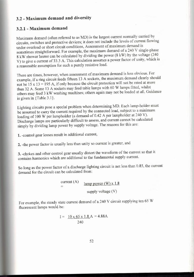
3.2 - Maximum demand and diversity
3.2.1 - Maximum demand
Maximum demand ( often referred to as MD) is the largest current normally carried by circuits, switches and protective devices; it does not include the levels of current flowing under overload or short circuit conditions, Assessment of maximum demand is sometimes straightforward. For example, the maximum demand of a 240 V single-phase 8 kW shower heater can be calculated by dividing the power (8 kW) by the voltage (240 V) to give a current of 3 3 .3 A. This calculation assumes a power factor of unity, which is a reasonable assumption for such a purely resistive load.
There are times, however, when assessment of maximum demand is less obvious. For example, if a ring circuit feeds fifteen 13 A sockets, the maximum demand clearly should not be 15 x 13 = 195 A, if only because the circuit protection will not be rated at more than 32 A. Some 13 A sockets may feed table lamps with 60 W lamps fitted, whilst others may feed 3 kW washing machines; others again may not be loaded at all. Guidance is given in {Table 3.1}.
Lighting circuits pose a special problem when determining MD. Each lamp-holder must be assumed to carry the current required by the connected load, subject to a minimum loading of 100 W per lampholder (a demand of 0.42 A per lampholder at 240 V). Discharge lamps are particularly difficult to assess, and current cannot be calculated simply by dividing lamp power by supply voltage. The reasons for this are:
1. -control gear losses result in additional current,
2. -the power factor is usually less than unity so current is greater, and
3. -chokes and other control gear usually distort the waveform of the current so that it contains harmonics which are additional to the fundamental supply current.
So long as the power factor of a discharge lighting circuit is not less than 0.85, the current demand for the circuit can be calculated from:
current (A) lamp power (W) x 1.8
supply voltage (V) =
For example, the steady state current demand of a 240 V circuit supplying ten 65 W fluorescent lamps would be:
I = 10 x 65 x 1.8 A = 4.88A 240
52

Switches for circuits feeding discharge lamps must be rated at twice the current they are required to carry, unless they have been specially constructed to withstand the severe arcing resulting from the switching of such inductive and capacitive loads.
I Table 3.1 - Current demand of outlets
\ Type of outlet \ Assumed current demand
I 2 A socket outlet I At least O.SA I Other socket outlets I Rated current
I Lighting point Connected load, with minimum of 100 W
Shaver outlet, bell transformer or any May be neglected
Iequipment of 5 W or less
I Household cooker lOA + 30% of remainder+ 5A for socket in cooker unit
When assessing maximum demand, account must he taken of the possible growth in demand during the life of the installation. Apart from indicating that maximum demand must be assessed, the Regulations themselves give little help. Suggestions for the assumed current demand of various types of outlet are shown in {Table 3. 1}.
3.2.2 - Diversity
A domestic ring circuit typically feeds a large number of 13 A sockets hut is usually protected by a fuse or circuit breaker rated at 30 A or 32 A. This means that if sockets were feeding 13 A loads, more than two of them in use at the same time would overload the circuit and it would be disconnected by its protective device.
In practice, the chances of all domestic ring sockets feeding loads taking 13 A is small. Whilst there maybe a 3 kW washing machine in the kitchen, a 3 kW heater in the living room and another in the bedroom, the chance of all three being in use at the same time is remote. If they are all connected at the same time, this could be seen as a failure of the designer when assessing the installation requirements; the installation should have two ring circuits to feed the parts of the house in question.
Most sockets, then, will feed smaller loads such as table lamps, vacuum cleaner, television or audio machines and so on. The chances of all the sockets being used simultaneously is remote in the extreme provided that the number of sockets (and ring circuits) installed is large enough. The condition that only a few sockets will be in use at the same time, and that the loads they feed will be small is called diversity.
53

By making allowance for reasonable diversity, the number of circuits and their rating can be reduced, with a consequent financial saving, but without reducing the effectiveness of the installation. However, if diversity is over-estimated, the normal current demands will exceed the ratings of the protective devices, which will disconnect the circuits - not a welcome prospect for the user of the installation! Overheating may also result from overloading which exceeds the rating of the protective device, but does not reach its operating current in a reasonably short time. The Regulations require that circuit design should prevent the occurrence of small overloads of long duration.
The sensible application of diversity to the design of an installation calls for experience and a detailed knowledge of the intended use of the installation. Future possible increase in load should also be taken into account. Diversity relies on a number of factors which can only be properly assessed in the light of detailed knowledge of the type of installation, the industrial process concerned where this applies, and the habits and practices of the users, Perhaps a glimpse into a crystal ball to foresee the future could also be useful!
In many situations there is a need for socket outlets to be closely spaced so that they are available to feed appliances and equipment without the need to use long and potentially dangerous leads. For example, the domestic kitchen worktop should be provided with ample sockets to feed the many appliances ( deep fat fryer, kettle, sandwich toaster, carving knife, toaster, microwave oven, coffee maker, and so on) which are likely to be used. Similarly, in the living room we need to supply television sets, video recorders, stereo players, table lamps, room heaters, etc. In this case, more outlets will he needed to allow for occasional rearrangement of furniture, which may well obstruct access to some outlets.
3.3 - BS1363 socket outlet circuits
3.31 - The fused plug
If each one of these socket outlets were wired back to the mains position or to a local distribution board, large numbers of circuits and cables would be necessary, with consequent high cost. The alternative is the provision of fewer sockets with the penalties of longer leads and possibly the use of multi-outlet adaptors. Because the ideal situation will have closely-spaced outlets, there is virtually no chance of more than a small proportion of them being in use at the same time, so generous allowance can be made for diversity. Thus, cables and protective devices can safely he smaller in size than would he needed if it were assumed that all outlets were simultaneously fully loaded.
Thus a ring circuit protected by a 30 A or 32 A device may well feed twenty socket outlets. It follows that judgment must be used to make as certain as possible that the total loading will not exceed the protective device rating, or its failure and inconvenience will result. Two basic steps will normally ensure that a ring circuit is not overloaded.
54

1. - Do not feed heavy and steady loads (the domestic immersion heater is the most obvious example) from the ring circuit, but make special provision for them on separate circuits.
2. -Make sure that the ring circuit does not feed too great an area. This is usually ensured by limiting a single ring circuit to sockets within an area not greater than one hundred square meters.
Fig 3.3 Plug and socket to BS 1363
We have already indicated that a 30 A or 32 A fuse or circuit breaker is likely to protect a large number of outlets. If this were the only method of protection, there could be a dangerous situation if, for example, a flexible cord with a rating of, say, 5 A developed a fault between cores. The fuse is inside the BS 1363 plug, and is rated at 13 A or 3 A, although many other ratings up to 12 A, which are not recognized in the BSS, are available.
A plug to BS 1363 without a fuse is not available. The circuit protection in the distribution board or consumer's unit covers the circuit wiring, whilst the fuse in the plug protects the appliance and its cord as shown in {Fig 6.4}. In this way, each appliance can be protected by a suitable fuse, for example, a 3 A fuse for a table lamp or a 13 A fuse for a 3 kW fan heater.
Whilst the installer of the wiring is seldom concerned with the flexible cords of appliances connected to it, he must still offer guidance to users. This will include fitting 3 A fuses in plugs feeding low rated appliances, and the use of flexible cords which are of sufficient cross-section and are as short as possible in the circumstances concerned.
55

Generally, 0.5 mm2 cords should be the smallest size connected to plugs fed by 30 A or 32 A ring circuits. Where the cord length must he 1 O m or greater, the minimum size should be 0.75 mm2 and rubber-insulated cords are preferred to those that are PVC insulated.
This type of outlet is not intended for use at high ambient temperatures. A common complaint is the overheating of a fused plug and socket mounted in an airing cupboard to feed an immersion beater; as mentioned above, it is not good practice to connect such a load to a ring circuit, and if unavoidable, final connection should be through a fused spur outlet.
appliance and its trexible cordprotected by 13 A fuse
appliance
13 A fuse in plug30 A circuit protective device
I >-=-<"-------~ ! ç; ~il'c~it -pmt~cted by 30 A devrce X..__ __
Fig 3.4 Principle of appliance protection by plug fuse
The British fused plug system is probably the biggest stumbling block to the introduction of a common plug for the whole of Europe (the 'europlug'). The proposed plug is a reversible two-pin type, so would not comply with the Regulations in terms of correct polarity. Ifwe were to adopt it, every plug would need adjacent fuse protection, or would need to be rewired back to its own protective device. In either case, the cost would be very high.
Ring circuits fed from systems where no earth terminal is provided by the Electricity Supply Company (TT systems) must be protected by an RCD rated at 30 mA, In all installations, a socket intended to feed equipment outdoors must be individually protected by a 30 mA RCD.
Where a socket is mounted on a vertical wall, its height above the floor level or
the working surface level level must be such that mechanical damage is unlikely. A minimum mounting height of 150 mm is recommended.
3.3.2 - The ring final circuit
The arrangement of a typical ring circuit is shown in {Fig 3.5} and must comply with the following requirements.
56

Fig 3.5 Ring circuit feeding socket outlets to BS 1363
1. - The floor area served by each ring must not exceed 100 m2 for domestic situations, Where ring circuits are used elsewhere ( such as in commerce or industry) the diversity must be assessed to ensure that maximum demand will not exceed the rating of the protective device.
2. - Consideration should be given to the provision of a separate ring ( or radial) circuit in a kitchen.
3. - Where there is more than one ring circuit in the same building, the installed sockets should be shared approximately evenly between them.
4. - Cable sizes for standard circuits are as follows:
a) p.v.c. insulated cable are 2.5 mm2 for live (phase and neutral) conductors and 1 .5mm2 for the CPC.
b) mineral insulated: 1 .5mm2for all conductors.
These sizes assume that sheathed cables are clipped direct, are embedded in plaster, or have one side in contact with thermally insulating material. Single core cables are
57

assumed to be enclosed in conduit or trunking. No allowance has been made for circuits which are bunched, and the ambient temperature is assumed not to exceed 30°C.
5. - The number of unfused spurs fed from the ring circuit must not exceed the number of sockets or fixed appliances connected directly in the ring.
6. - Each non-fused spur may feed no more than one single or one twin socket, or no more than one fixed appliance.
7. - Fixed loads fed by the ring must be locally protected by a fuse ofrating no greater than 13 A or by a circuit breaker of maximum rating 16 A.
8. - Fixed equipment such as space heaters, water heaters of capacity greater than 15 liters, and immersion heaters, should not be fed by a ring, but provided with their own circuits.
3.3.3 - The radial circuit
Two types of radial circuit are permitted for socket outlets. In neither case is the number of sockets to be supplied specified, so the number will be subject to the constraints of load and diversity. The two standard circuits are:
1. - 20 A fuse or miniature circuit breaker protection with 2.5 mm2 live and l.5mm2
protective conductors ( or 1.5 mm2 if m.i. cable) feeding a floor area of not more than 50 m2• If the circuit feeds a kitchen or utility room, it must be remembered that a 3 kW device such as a washing machine or a tumble dryer takes 12.5 A at 240 V and that this leaves little capacity for the rest of the sockets.
2. - 32 A cartridge fuse to B888 or miniature circuit breaker feeding through 4 mm2 live and 2.5 mm2 protective conductors (or 2.5 mm2 and 1.5 mm2 if m.i. Cable) to supply a floor area no greater than 75m2•
The arrangement of the circuits is shown in (Fig 3.6). 4mm2 may seem to be a large cable size in a circuit feeding 13 A sockets. It must be remembered, however, that the 2.5 mm2
ring circuit allows current to be fed both ways round the ring, so that two conductors are effectively in parallel, whereas the 4 mm2 cable in a radial circuit must carry all the current.
58

IT:iJ r.w ----- .
Fig 3.6 - Radial circuits
Radial circuits can be especially economic in a long building where the completion of a ring to the far end could effectively double the length of cable used. As for ring circuits, danger can occur if flexible cords are too small in cross-section, or are too long, or if 3 A fuses are not used where appropriate.
The minimum cross-sectional area for flexible cords should be:
0.5mm2 where the radial circuit is protected by a 16 A fuse, 0.75mm2 for a 20 A fuse, or l .Omm2 for a 30 A or 32 A fuse.
3.4 - Industrial socket outlet circuits
3.4.1 - Introduction
There is no reason at all to prevent the installation of BS 1363 (13 A) socket outlets in industrial situations. Indeed, where light industry, such as electronics manufacture, is concerned, these sockets are most suitable. However, heavy duty industrial socket outlets are available, and this type is the subject of this section.
59

3.4.2 - BS 196 socket outlet circuits
BS 196 sockets are two-pin, non-reversible, with a scraping earth connection. The fusing in the plug can apply to either pole, or the plug may be unfused altogether. Interchangeability is prevented by means of a keyway which may have any of eighteen different positions, identified by capital letters of the alphabet (see {Fig 3.7}). They are available with current ratings of 5 A, 15 A or 30 A.
/ B - position of keyway • B'
total of 18different keyway positions
' I P - position of keyway 'P'
Fig 3. 7 Arrangement of socket outlet to BS 196. Two of the eighteen possible keyway positions are shown
Circuit details for wiring ES 196 outlets can be summarized as:
1. - the maximum protective device rating is 32 A
2. - all spurs must be protected by a fuse or circuit breaker of rating no larger than 16 A - this means that 30 A outlets cannot be fed from spurs
3. - the number of sockets connected to each circuit is unspecified, but proper judgment must be applied to prevent failure of the protective device due to overload
4. - cable rating must be no less than that of the protective device for radial circuits, or two thirds of the protective device rating for a ring circuit
5. - on normal supplies with an earthed neutral, the phase pole must be fused and the keyway must be positioned at point B (see {Fig 3.7})
6. - when the socket is fed at reduced voltage from a transformer with the centre tap on its secondary winding earthed {Fig 3.8}, both poles of the plug must be fused and the keyway must be positioned at P.
60
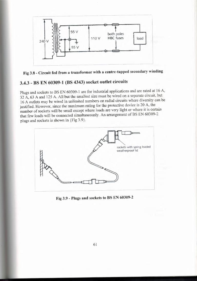
55V both poles HBC fuses load110V
240V
i 55V
Fig 3.8 - Circuit fed from a transformer with a centre-tapped secondary winding
3.4.3 - BS EN 60309-1 (BS 4343) socket outlet circuits
Plugs and sockets to BS EN 60309-1 are for industrial applications and are rated at 16 A, 32 A, 63 A and 125 A. All but the smallest size must be wired on a separate circuit, but 16 A outlets may be wired in unlimited numbers on radial circuits where diversity can be justified. However, since the maximum rating for the protective device is 20 A, the number of sockets will be small except where loads are very light or where it is certain that few loads will be connected simultaneously. An arrangement of BS EN 60309-2 plugs and sockets is shown in {Fig 3.9}.
sockets with spring loaded weatherproof lid
Fig 3.9 - Plugs and sockets to BS EN 60309-2
61
3.5 - Circuit segregating
3.5.1 - Segregating circuits
The 15th and 16th editions of the IEE Wiring Regulations applied segregation of circuits which need to be kept apart by classifying them in four separate categories (the Rags themselves only mentioned three categories, but since two types of circuit both categorized as 3 had to be separated from each other, there were effectively four categories).
The second amendments to BS 7671 (published in 1997) have simplified the situation. There are now only two categories, which are known as voltage bands.
Voltage Band I is defined as levels of voltage which are too low to provide serious electric shocks; effectively this limits the band to extra-low voltage (EL V), including telecommunications, signaling, bell, and control and alarm circuits.
Voltage Band II covers all voltages used in electrical installations not included in Band I. This means that all 230/400 V (240/415 V) supplies are included in Band II.
As expected, BS 7671 prohibits Band I and Band II cables sharing the same cable enclosure or multicore cable unless: every cable is insulated for the highest voltage present, or each conductor in a multicore cable is insulated for the highest voltage present, unless conductors of the two bands are separated by an earthed metal screen, or they are installed in separate compartments of a trunking or ducting system, or they are installed on a tray with a partition providing separation, or a separate conduit or ducting system is provided for each band.
This does mean that BS 7671 allows circuits such as those for fire alarm Systems, emergency lighting, telephones, data transmission, intruder alarms, sound systems, bell and call systems, etc., may now be run together without segregation. BS 5838: 1988, on the other hand. makes it clear that fire alarm cables must be separated from all others, and IEE Guidance Note 4 requires that escape lighting cables should be mineral insulated or separated from all others by at least 300 mm. Care must be taken to ensure that circuits are not affected by electrical interference, both electrostatic (due to electric fields) or electro-magnetic ( due to electro-magnetic fields). In some ways this makes the circuit designer's task more difficult, because he must now ensure that there will be no interference, whereas before, he simply had to ensure that the required segregation was employed.
In some instances it will be necessary for circuit outlets for both voltage bands to share a common box; switchplate or block. In such a case, the connections of circuits of differing bands must be segregated by a partition, which must be earthed if of metal.
62

3.5.2 - Electromagnetic compatibility
All electrical equipment must be selected and installed so that it will not affect the supply or cause harmful effects to other equipment. One of the harmful effects is electromagnetic interference (EMI). Whenever current flows in a conductor it sets up a magnetic field; a change in the current will result in a corresponding change in the magnetic field, which will result in the induction of electromotive force (voltage) in any conducting system subject to the field. Whilst induced voltages will usually be very small, they may be considerable when rates of change of current are heavy (for example, circuits feeding lift motors) or when there is a lightning strike in the vicinity.
The effects are most pronounced when large metal loops are formed by circuits (perhaps power and data circuits) which are run at a distance from each other but have common earthing and bonding. Power and data cables need to follow common routes to prevent aerial loops which will be subject to induced e.m.f., but with sufficient spacing to prevent interference between them (see {Table 3.2}). The emission standard is BS EN 50081 and the immunity standard BS EN 50082.
The designer needs to consider EMC when planning an installation, and may decide that some of the following measures are appropriate:
providing surge protectors and filters for sensitive equipment, proper separation of power and other cables to limit electro-magnetic interference (EMI), using bonding connections which are as short as possible, screening sensitive equipment and bonding of metal enclosures, and avoiding inductive loops by using the same route for cables of different systems.
" '=This list.is.far.from exhaustive.
I Table 3.2 - Proposed EMI cable separation distances I
Power I
cable Min. separation btw Power Min separation btw voltage power & signal cable power & signal
cables, m current cables, m
jl 15 V r 0.25 I 5A I 0.24
1240V I 0.45 I 15 A I 0.35
j415 V I 0.58 I 50A I 0.50
j3.3 kV I 1.10 I 100 A I 0.60
j6.6 kV -, 1.25 1300A ı 0.85
I 11 kV I 1.40 1600A I 1.05
63

3 .5 .3 - lift or hoist shaft circuits
A lift shaft may well seem to be an attractive choice for running cables, but this is notpermitted except for circuits which are part of the lift or hoist installation (see {Fig3 .1 O}). The cables of the lift installation may be power cables fixed in the shaft to feedthe motor(s), or control cables which feed call buttons, position indicators, and so on.Trailing cables will feed call buttons, position indicators, lighting and telephones in thelift itself.
trailing cabl
fixed cablesfor lift on!
Fig 3.10 - Cables installed in lifts or hoist shafts
64

Chapter 4
4.1 - The earthling principle
4.1.1 - What is earthling?
The whole of the world may be considered as a vast conductor which is at reference(zero) potential. In the UK we refer to this as 'earth' whilst in the USA it is called'ground'. People are usually more or less in contact with earth, so if other parts which areopen to touch become charged at a different voltage from earth a shock hazard exists. Theprocess of earthling is to connect all these parts which could become charged to thegeneral mass of earth, to provide a path for fault currents and to hold the parts as close aspossible to earth potential. In simple theory this will prevent a potential differencebetween earth and earthed parts, as well as permitting the flow of fault current which willcause the operation of the protective systems.
The standard method of tying the electrical supply system to earth is to make a directconnection between the two. This is usually carried out at the supply transformer, wherethe neutral conductor (often the star point of a three-phase supply) is connected to earthusing an earth electrode or the metal sheath and armouring of a buried cable. {Figure 4. 1}shows such a connection. Lightning conductor systems must be bonded to the installationearth with a conductor no larger in cross-sectional area than that of the earthingconductor.
65

R A2
Al
starpoint
B------+------ı----cı
C1
eart.h"':"" .. electırode
Fig 4.1 - Three-phase delta/star transformershowing earthing arrangements
4.1.2 - The advantages of earthing
The practice of earthing is widespread, but not all count:ı;ies in the world use it.
There is certainly a high cost involved, so there must be some advantages. In factthere are two. They are:
1. - The whole electrical system is tied to the potential of the general mass of earth andcannot 'float' at another potential. For example, we can be fairly certain that the neutral ofour supply is at, or near, zero volts (earth potential) and that the phase conductors of ourstandard supply differ from earth by 240 volts.
2. - By connecting earth to metalwork not intended to carry current (an extraneousconductive part or a an exposed conductive part) by using a protective conductor, a pathis provided for fault current which can be detected and, if necessary, broken. The path forthis fault current is shown in {Fig 4.2}.
66

path for earth fault current••••---- -------- e:::st =i,
exposedconductive parts
Fig 4.2 Path for earth fault current (shown by arrows)
4.1.3 - The disadvantages of earthling
The two important disadvantages are:
1. - Cost: the provision of a complete system of protective conductors, earth electrodes,etc. is very expensive.
2. - Possible safety hazard: It has been argued that complete isolation from earth willprevent shock due to indirect contact because there is no path for the shock current toreturn to the circuit if the supply earth connection is not made (see {Fig 4.3(a)} ). Thisapproach, however, ignores the presence of earth leakage resistance (due to imperfectinsulation) and phase-to-earth capacitance (the insulation behaves as a dielectric). Inmany situations the combined impedance due to insulation resistance and earth capacitivereactance is low enough to allow a significant shock current (see {Fig 4.3(b)} ).
67

a) b)
Fig 4.3 - Danger in an unearthed system
a) Apparent safety: no obvious path for shock currentb) actual danger: shock current via stray resistance and capacitance
4.2 - Earth fault loop impedance
4.2.1 - The importance of loop impedance
The earth fault loop impedance can be used with the supply voltage to calculate the earthfault current.
IF= UoZsIF = fault current, AUo = phase voltage, VZs = loop impedance
where
For example, if a 240 V circuit is protected by a 15 A semi-enclosed fuse and has anearth-fault loop impedance of 1.6 Ohms, the earth-fault current in the event of a zeroimpedance earth fault will he:
IF Uo 240= 150 A= A
=Zs 1.6
This level of earth-fault current will cause the fuse to operate quickly. The time taken forthe fuse to operate will be about 0.15 s. Any load current in the circuit will be additionalto the fault current and will cause the fuse to operate slightly more quickly. However,such load current must not be taken into account when deciding disconnection time,because it is possible that the load may not be connected when the fault occurs.
68

Note that there is no such thing as a three-phase line/earth fault, although it is possible forthree faults to occur on the three lines to earth simultaneously. As far as calculations forfault current are concerned, the voltage to earth for standard UK supplies is always 240V, for both single-phase and three-phase systems. Thus the Tables of maximum earthfault loop impedance which will be apply both to single- and to three-phase systems.
4.2.2 - Earth-fault loop impedance values
The over-riding requirement is that sufficient fault current must flow in the event of anearth fault to ensure that the protective device cuts off the supply before dangerous shockcan occur. For normal 240 V systems, there are two levels of maximum disconnectiontime. These are:
For socket outlet circuits where equipment could be tightly grasped: 0.4 s
For fixed equipment where contact is unlikely to be so good: 5 s
The maximum disconnection time of 5 s also applies to feeders and sub-mains.
It must be appreciated that the longest disconnection times for protective devices, leadingto the longest shock times and the greatest danger, will be associated with the lowestlevels of fault current, and not, as is commonly believed, the highest levels.
Where the voltage is other than 240 V, [Table 41 A] gives a range of disconnection timesfor socket outlet circuits, of which the lowest is O. 1 s for voltages exceeding 400 V.
In general, the requirement is that if a fault of negligible impedance occurs between aphase and earth, the earth-fault loop impedance must not be greater than the valuecalculated from ..
Zs< UoIa
where Zs= the earth fault loop impedance (Ohms)Uo = the system voltage to earth(V)Ia = the current causing automatic disconnection(operation of the protective device) in the required time[A]).
The earth fault loop values shown in (Tables 4.1,4.2 and 4.4)depend on the supplyvoltage and assume, as shown in the Tables, a value of240 V. Whilst it would appear that240 Vis likely to be the value of the supply voltage in Great Britain for the foreseeablefuture, it is not impossible that different values may apply. In such a case, the tabulatedvalue for earth fault loop impedance should be modified using the formula:-
69

70
Zs= Zt x _Jl U240
where Zs= is the earth fault loop impedance required forsafety
_ is the tabulated value of earth fault loop- impedance
U = is the actual supply voltageU240 = is the supply voltage assumed in the Table.
Zt
As an alternative to this calculation, a whole series ofmaximum values of earth fault loopimpedance is given in(Table5.1) for disconnection within 0.4 s. The reader should notthink that these values are produced in some mysterious way - all are easily verified usingthe characteristic curves
For example, consider a 20 A HRC fuse to BS88 used in a 240 V system.and indicatesthat disconnection in 0.4 s requires a current of about 130 A. It is difficult (ifnotimpossible) to be precise about this value of current, because it is between the 100 A and150 A current graduations.
Using these values,Zs Vo = 240 Ohms= 1.84 Ohms
=
Ia 130
Reference to (Table 4.1) shows that the stated value is 1.8 Oh,s, the discrepancy beingdue to the difficulty in reading the current with accuracy. (Tables4.1 and 4.2) givemaximum earth-fault loop impedance values for fuses and for miniature circuit breakersto give a minimum disconnection time of 0.4 s in the event of a zero impedance faultfrom phase to earth.
The reason for the inclusion of fixed equipment as well as distribution circuits in (Table4.2) will become apparent later in this sub-section.

- Table 4.1 - Maximum earth-fault loop impedance for 240 V socket
i outlet circuits protected by fuses
r Fuse rating I Maximum earth-fault loop impedance (Ohms)I (A)~----
Cartridge I Cartridge BS ı-·Semi-enclosed
I I- BS 88 1361 I BS3036I
I 5 I- I 10.9 I 10.0I !ı 6 ıs.-89--1 - ı10 i 5.33 - r
I
15 I i 3.43 [ 2.67I - I,------ [20 I 1.85 I 1.78 I 1.85I
30 I - I 1.20 ! 1.14I
32 I 1.09
40 I 0.86I
45 I I 0.60 I 0.62I - I I
If Table 4.2 - Maximum earth-fault loop impedance for 240 V circuitprotected by miniature circuit breakers to give compliance with
I 0.4 s disconnection time
l - ! Maximum earth-fault loop impedance (Ohms)
f Device I MCB I MCB j MCB ~,--I _M_C_B_\ ratıng I I type 3 I ~~:~I (A) ı type 1 I type 2 and type C ! type B I type D
I 5 I 12.00 I 6.86 I 4.80 I - 12.40------
8.oo I 2.00I4.80 I 1.20I
I 15 !4.00-J 2.29 ı--1.60 ~! -----! 0.80----------ı------- ---- ·r·----- -----,----------------,-----------,------------1 16 I 3.75 I 2.14 I 1.50 I 3.00 I 0.75. I I I Ij 20 I 3.00 I 1.71 I 1.20 i 2.40 1 0.60
25 ı 2.40 I 1.31 'ı o.96 I 1.92 r, o.48j \ I !,-----· r------- ,------r-·------ r: l 30 I 2.00 I 1.14 J 0.80 I - I 0.40r---ı"" .j 32 I 1.88 I 1.07 I 0.75 i 1.50 \ 0.38I I40 ı 1.5
6 10.00 5.71 4.00
10 6.00 3.43 2.40
0.86 0.60 1.20 0.30
71

The severity of the electric shock received when there is a phase to earth fault (indirectcontact) depends entirely on the impedance of the circuit protective conductor. We sawhow the volt drop across the protective conductor is applied to the person receiving theshock. Since this volt drop is equal to fault current times protective conductor impedance,if the protective conductor has a lower impedance the shock voltage will he less. Thus itcan be sustained for a longer period without extreme danger.
Socket outlet circuits can therefore have a disconnection time of up to 5 s provided thatthe circuit protective conductor impedance's are no higher than shown in {Table 4.3} forvarious types of protection.
The reasoning behind this set of requirements becomes clearer if we take an example.{Table 4.3} shows that a 40 A cartridge fuse to BS 88 must have an associated protectiveconductor impedance of no more than 0.29 Ohms if it is to comply. Now look at thetime/current characteristic for the fuse from which we can see that the current foroperation in 5 s is about 170 A. The maximum volt drop across the conductor (the shockvoltage) is thus 170 x 0.29 or 49.3 V.
72

Table 4.3 - Maximum impedance of circuit protective conductors to allow 5 s disconnection time for socket outlets
Maximum impedance of circuit protective conductor
ı\ ...---------1 Fuse ~\ ~I ı G;Çı· Ratin BS Fuse Fuse MCB MCB MCB MCB MCB
g BS BS type 3 type \(A) 88 1361 3036 type 1 \ type 2 & C \type B D
I I I. . ı I .
5 ı- I 3.25 I 3.25 fı.501 ı.43 -I 1-.00-I-[ o.so
6 ! 2.48 ı-ı - I 2.08 ! 1.19 I 0.83 I 1.67 lü.42ı ıo 11.481-ı - ı 1.2s fo.71-fo:sc>f ı.oo 1 0.25jLl!-_1°~961 0.96-10.83 l°A8!D33_1-_ı_- -I 16 Jü.831-1-1°'781 0.45 I 0.31 I 0.63 I 0.16 I
I 20 fo.ssjü.551 0.63 I 0.63 1°361 0.25 iü.501 0.12 '
I 25 I o.43 1-1-1-1-1"-, - ıo.io30 I - 1°361 0.43 I 0.42 I 0.24 I 0.17 I - I --32-\ o.34 ı - 1-1o.39 1°221 0.16 I o.31 \Q.084()\0.261-ı - \ 0.31 fa.isl 0.13 \ü.25fo.06,4.51 - ıo.ısl 0.24 \ 0.28 I 0.16 \ 0.11 I 0.22 \ 0.06 _J
73

Table 4.4 - Maximum earth-fault loop impedance for 240 V fixed equipment distribution circuits protected by fuses
IMaximum earth-fault loop impedance
I,--
Device Cartridge I Cartridge I Semi-enclosedrating I I
I
(A) I BS 88 BS 1361 I BS 3036
5 I - I 17.1! I!----, 14.1--r-
6 I - I
i i
I 10 I 7.74II 15 I i 5.22 I 5.58I - II I
I 16 I 4.36II
i
20 I 3.04 I 2.93 I 4.00I
I 30 I - ıı.92 I 2.76
I 32 I 1.92II 40 I 1.41 I - II II 45 -ı - I 1.00 I 1.66
I I\-50-, 1.09 r--=---
!
Application of the same reasoning to all the figures gives shock voltages ofless than 50V. This limitation on the impedance of the CPC is of particular importance in TT systemswhere it is likely that the resistance of the earth electrode to the general mass of earth willbe high.
The breaking time of 5 s also applies to fixed equipment, so the earth-fault loopimpedance values can be higher for these circuits, as well as for distribution circuits. Forfuses, the maximum values of earth-fault loop impedance for fixed equipment are givenin {Table4.4}.
No separate values are given for miniature circuit breakers. Examination of thetime/current characteristics will reveal that there is no change at all in the current causingoperation between 0.4 sand 5 sin all cases except the Type 1. Here, the verticalcharacteristic breaks off at 4 s, but this makes little difference to the protection. In thiscase, the values given in (Table 4.2) can be used for fixed equipment as well as for socketoutlet circuits. An alternative is to calculate the loop impedance as described above.
74

{Figure 4.4} shows a method of measuring the resistance of the protective conductor,using a line conductor as a return and taking into account the different cross-sectionalareas of the phase and the protective conductors.
4.2.3 - Protective conductors impedance
It has been shown in the previous sub-section how a low-impedance protective conductorwill provide safety from shock in the event of a fault to earth. This method can only beused where it is certain that the shock victim can never be in contact with conductingmaterial at a different potential from that of the earthed system in the zone he occupies.Thus, all associated exposed or extraneous parts must be within the equipotential zone.When overcurrent protective devices are used as protection from electric shock, theprotective conductor must be in the same wiring system as, or in close proximity to, thelive conductors. This is intended to ensure that the protective conductor is unlikely to hedamaged in an accident without the live conductors also being cut.
II E/P short circuit
. EE······N ·······--"'p ·-·····----
Al+Ap
Fig 4.4 - Measurement of protective conductor resistance
Taking the cross-sectional area of the protective conductor as Ap and that of the line(phase or neutral) conductor as Al , then
Rp = resistance reading AlX ------
4.3 - protective conductors
4.3.1 - Earthing conductors
The earthing conductor is commonly called the earthing lead. It joins the installationearthing terminal to the earth electrode or to the earth terminal provided by the ElectricitySupply Company. It is a vital link in the protective system, so care must be taken to seethat its integrity will be preserved at all times. Aluminum conductors and cables may nowbe used for earthling and bonding, but great care must be taken when doing so to ensure
75

that there will be no problems with corrosion or with electrolytic action where they comeinto contact with other metals.
Where the final connection to the earth electrode or earthling terminal is made there mustbe a clear and permanent label Safety Electrical Connection - Do not remove where aburied earthling conductor is not protected against mechanical damage but is protectedagainst corrosion by a sheath, its minimum size must be 16 mm2 whether made of copperor coated steel. If it has no corrosion protection, minimum sizes for mechanicallyunprotected earthling conductors are 25 mm2 for copper and 50 mm2 for coated steel.
If not protected against corrosion the latter sizes again apply, whether protected frommechanical damage or not.
Earthling conductors, as well as protective and bonding conductors, must be protectedagainst corrosion. Probably the most common type of corrosion is electrolytic, which isan electro-chemical effect between two different metals when a current passes betweenthem whilst they are in contact with each other and with a weak acid. The acid is likely tobe any moisture which has become contaminated with chemicals carried in the air or inthe ground. The effect is small on ac supplies because any metal removed whilst currentflows in one direction is replaced as it reverses in the next half cycle. For de Systems,however, it will be necessary to ensure that the system remains perfectly dry (a verydifficult task) or to use the 'sacrificial anode' principle.
A main earth terminal or bar must be provided for each installation to collect and connecttogether all protective and bonding conductors. It must be possible to disconnect theearthling conductor from this terminal for test purposes, but only by the use of a tool.This requirement is intended to prevent unauthorized or unknowing removal ofprotection.
4.3.2 - Bonding conductors
The purpose of the protective conductors is to provide a path for earth fault current sothat the protective device will operate to remove dangerous potential differences, whichare unavoidable under fault conditions, before a dangerous shock can be delivered.Equipotential bonding serves the purpose of ensuring that the earthed metalwork(exposed conductive parts) of the installation is connected to other metalwork(extraneous conductive parts) to ensure that no dangerous potential differences can occur.The resistance of such a bonding conductor must be low enough to ensure that its voltdrop when carrying the operating current of the protective device never exceeds 50 V.
76

: main earthing; terminal
if this section is insulated bondingmust be at B rather than A
bonding leadsfor sizes see [413-02)
Fig 4.5 Main bonding connections
Thus~ 50
whereIa
R is the resistance of the bonding conductorIa is the operating current of the protective device.
Two types of equipotential bonding conductor are specified.
1. - Main equipotentiol bonding conductors These conductors connect together the installation earthling system and the metalwork ofother services such as gas and water. This bonding of service pipes must be effected asclose as possible to their point of entry to the building, as shown in {Fig 4.5}. Metallicsheaths of telecommunication cables must be bonded, but the consent of the owner of thecable must he obtained before doing so. The minimum size of bonding conductors isrelated to the size of the main supply conductors (the tails) and is given in (Table 4.5).
2. - Supplementary bonding conductors These conductors connect together extraneous conductive parts - that is, metalworkwhich is not associated with the electrical installation but which may provide aconducting path giving rise to shock. The object is to ensure that potential differences inexcess of 50 V between accessible metalwork cannot occur; this means that the resistanceof the bonding conductors must be low (Figure 4.6) shows some of the extraneousmetalwork in a bathroom which must be bonded.
77

. Table 4.5 - Supplementary bonding conductor sizes
Circuitprotective
conductor sizeSupplementary bonding conductor size
C)•
The cross-sectional areas required for supplementary bonding conductors are shown in{Table 4.5}. Where connections are between extraneous parts only, the conductors maybe 2.5 mm2 if mechanically protected or 4 mm2if not protected. If the circuit protectiveconductor is larger than 1 O mm2, the supplementary bonding conductor must have at least
I
Not protected Mechanically protected
2.5 mm24.0 mm2
1.5 mm2 4.0 mm2 I 2.5 mm2
4.0 mm2 I 2.5 mm2I
4.0 mm2 1-.~2.5 mm2 ----
4.0 mın2 ! 4.0 mm2I~---------
6.0mm2
2.5 mm2
4.0 mm2
6.0mm2
10.0 mm2 6.0mm2
I
IIii
I________ __]
Fig 4.6 Supplementary bonding in a bathroom
78
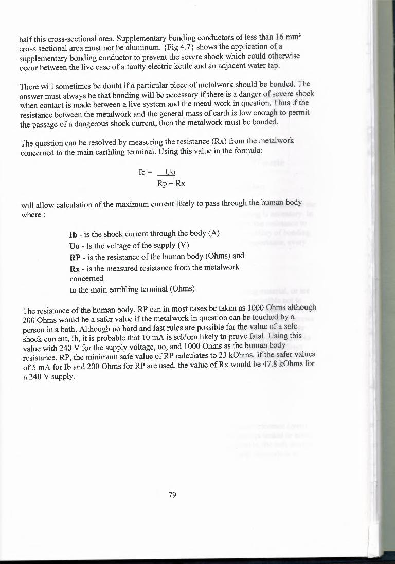
half this cross-sectional area. Supplementary bonding conductors of less than 16 mm2
cross sectional area must not be aluminum. {Fig 4. 7} shows the application of asupplementary bonding conductor to prevent the severe shock which could otherwiseoccur between the live case of a faulty electric kettle and an adjacent water tap.
lb= UoRp+Rx
There will sometimes be doubt if a particular piece of metalwork should be bonded. Theanswer must always be that bonding will be necessary if there is a danger of severe shockwhen contact is made between a live system and the metal work in question. Thus if theresistance between the metalwork and the general mass of earth is low enough to permitthe passage of a dangerous shock current, then the metalwork must be bonded.
The question can be resolved by measuring the resistance (Rx) from the metalworkconcerned to the main earthling terminal. Using this value in the formula:
will allow calculation of the maximum current likely to pass through the human bodywhere:
lb - is the shock current through the body (A)Uo - Is the voltage of the supply (V)RP - is the resistance of the human body (Ohms) andRx - is the measured resistance from the metalworkconcernedto the main earthling terminal (Ohms)
The resistance ofthe human body, RP can in most cases be taken as 1000 Ohms although200 Ohms would be a safer value if the metalwork in question can be touched by aperson in a bath. Although no hard and fast rules are possible for the value of a safeshock current, lb, it is probable that 1 O mA is seldom likely to prove fatal. Using thisvalue with 240 V for the supply voltage, uo, and 1000 Ohms as the human bodyresistance, RP, the minimum safe value of RP calculates to 23 kOhms. If the safer valuesof 5 mA for lb and 200 Ohms for RP are used, the value of Rx would be 47.8 kOhms fora 240 V supply.
79

water heateri
I socket outlet
II
I'
coldtap
supplementary bondingconductor
bonding connectionswaste
Fig 4.7 Supplementary bonding conductor in a kitchen
To sum up when in doubt about the need to bond metalwork, measure its resistance to themain earthling terminal. If this value is 50 kOhms or greater, no bonding is necessary. Ina situation where a person is not wet, bonding could be ignored where the resistance tothe main earthling terminal is as low as 25 kOhms. To reduce the possibility of bondingconductors being disconnected by those who do not appreciate their importance, everybonding connection should be provided with a label.
4.3.3 - Unearthed metalwork
If exposed conductive parts are isolated, or shrouded in non-conducting material, or aresmall so that the area of contact with a human body is limited, it is permissible not toearth them. Examples are overhead line metalwork which is out of reach, steelreinforcing rods within concrete lighting columns, cable clips, nameplates, fixing screwsand so on. Where areas are accessible only to skilled or instructed persons, and whereunauthorized persons are unlikely to enter due to the presence of warning notices, locksand so on, earthling may be replaced by the provision of obstacles which make directcontact unlikely, provided that the installation complies with the Electricity at WorkRegulations, 1989.
4.4 - earth electrodes
4.4.1 - Why we must have earth electrodes?
The principle of earthling is to consider the general mass of earth as a reference (zero)potential. Thus, everything connected directly to it will be at this zero potential or aboveit by the amount of the volt drop in the connection system (for example, the volt drop in aprotective conductor carrying fault current). The purpose of the earth electrode is toconnect to the general mass of earth.
80

With the increasing use of underground supplies and of protective multiple earthling(PME) it is becoming more common for the consumer to be provided with an earthterminal rather than having to make contact with earth using an earth electrode.
4.4.2 - Earth electrode types
Acceptable electrodes are rods, pipes, mats, tapes, wires, plates and structural steelworkburied or driven into the ground. The pipes of other services such as gas and water mustnot be used as earth electrodes although they must be bonded to earth as described in Thesheath and armour of a buried cable may be used with the approval of its owner andprovided that arrangements can be made for the person responsible for the installation tobe told if the cable is changed, for example, for a type without a metal sheath.
The effectiveness of an earth electrode in making good contact with the general mass ofearth depends on factors such as soil type, moisture content, and so on. A permanentlywet situation may provide good contact with earth, but may also limit the life of theelectrode since corrosion is likely to be greater. If the ground in which the electrode isplaced freezes, there is likely to be an increase in earth resistance. In most parts of theUK an earth electrode resistance in the range 1 Ohm to 5 Ohms is considered to beacceptable.
The method of measuring the resistance of the earth electrode will be considered in theresistance to earth should be no greater than 220 Ohms. The earthling conductor and itsconnection to the earth electrode must be protected from mechanical damage and fromcorrosion. Accidental disconnection must be avoided by fixing a permanent label asshown in {Fig 4.8} which reads:
I'label at connection /I
IJıetters at feastj4.75 mm hlgh
III
Fig 4.8 Connection of earthling conductor to earth electrode
81

4.5 - Earthed concentric wiring
4.5.1 - What is earth concentric wiring?
This is the TN-C system where a combined neutral and earth (PEN) conductor is usedthroughout the installation as well as for the supply. The PEN conductor is the sheath of acable and therefore is concentric with (totally surrounds) the phase conductor(s). Thesystem is unusual, but where employed almost invariably uses mineral insulated cable,the metallic copper sheath being the combined neutral and earth conductor.
4.5.2 - Requirements for earthed concentric wiring
Earthed concentric wiring may only be used under very special conditions, which usuallyinvolve the use of a private transformer supply or a private generating plant. Since thereis no separate path for earth currents, it follows that residual current devices (Reds) willnot be effective and therefore must not be used. The cross-sectional area of the sheath(neutral and earth conductor) of a cable used in such a system must never be less than 4mm2 copper, or 16 mm2 aluminum or less than the inner core for a single core cable. Allmulticore copper mineral insulated cables comply with this requirement, even a I mm2
two core cable having the necessary sheath cross-sectional area. However, only singlecore cables of 6 mm2 and below may be used. The combined protective and neutralconductors (sheaths) of such cables must not serve more than one final circuit.
Wherever a joint becomes necessary in the PEN conductor, the contact through thenormal sealing pot and gland is insufficient; an extra earth tail must be used as shown in{Fig 4.9}. If it becomes necessary to separate the neutral and protective conductors at anypoint in an installation, they must not be connected together again beyond that point.
II
I
l,ıearth tail J
Fig 4.9 Earth tail seal for use in earthed concentric wiring
4.6 - Combined functional and protective earthling
The previous section has made it clear that high earth leakage currents can causedifficulties in protection. The increasing use of data processing equipment such ascomputers has led to the need for filters to protect against transients in the installationwhich could otherwise result in the loss of valuable data. Such filters usually includecapacitors connected between live conductors and earth. This has led to large increases in
82

normal earth currents in such installations, and to the need for special regulations forthem. Since these are special situations, they will be considered in.
Electrical disturbances on the earth system (known as 'earth noise') may causemalfunctions of computer based systems, and 'clean' mains supplies and earthsystems may be necessary. A separate earthling system may be useful in such a caseprovided that:
Supplementary bonding between the computer earth system and extraneous conductiveparts is not necessary. be lost, and the fault current needed to operate the protectivedevice (single-phase circuit current would be 125 A at 240 V) would be high enough tocause a fire danger at the outlet where the fault occurred. The correct approach would beto divide the load into smaller circuits, each feeding, perhaps, ten lamps.
1. - the computer system has all accessible conductive parts earthed,
2. - the main earthling terminal of the computer earth system is connected directly to themain earthling terminal, ·
3. - all extraneous conductive parts within reach of the computer system are earthed to themain earthling terminal and not to the separate computer earth.
2. - to enable part of an installation to be switched off for maintenance or for testingwithout affecting
83

CHAPTER FIVE: Calculation
A.M.EAv¢roıal = rı
ILLUMINATION CALCULATIONS
1. AVERAGE LIGHTING CALCULATIONS At working plane the luminance at the related with dimension of the room and position
of the lamps with maintenance of the lamp can be calculated by
Where; 0totaI = the total luminance flux...... Eav =average luminance
11 = utilization factor
M = maintenance factor
A = the area of working place
ah K = h(a+b)
Where; K= Room Index, a = the length of the working plane, b = width of the
working plane, h = distance between lamps and working plane
h= H-(hl-h2) ..... H = distance between lamps and ceiling, hl = distance of working,
h2 = to length of lamp.
11 can be found by using the tables if the color of the wall, ground and ceiling are know
and the room index is calculated.
• Lighting calculation for car serves The measurements are taken from the AUTOCAD of the room where
a= 26.32m
b= 22.8m
A= axb = 600.096 m2
84
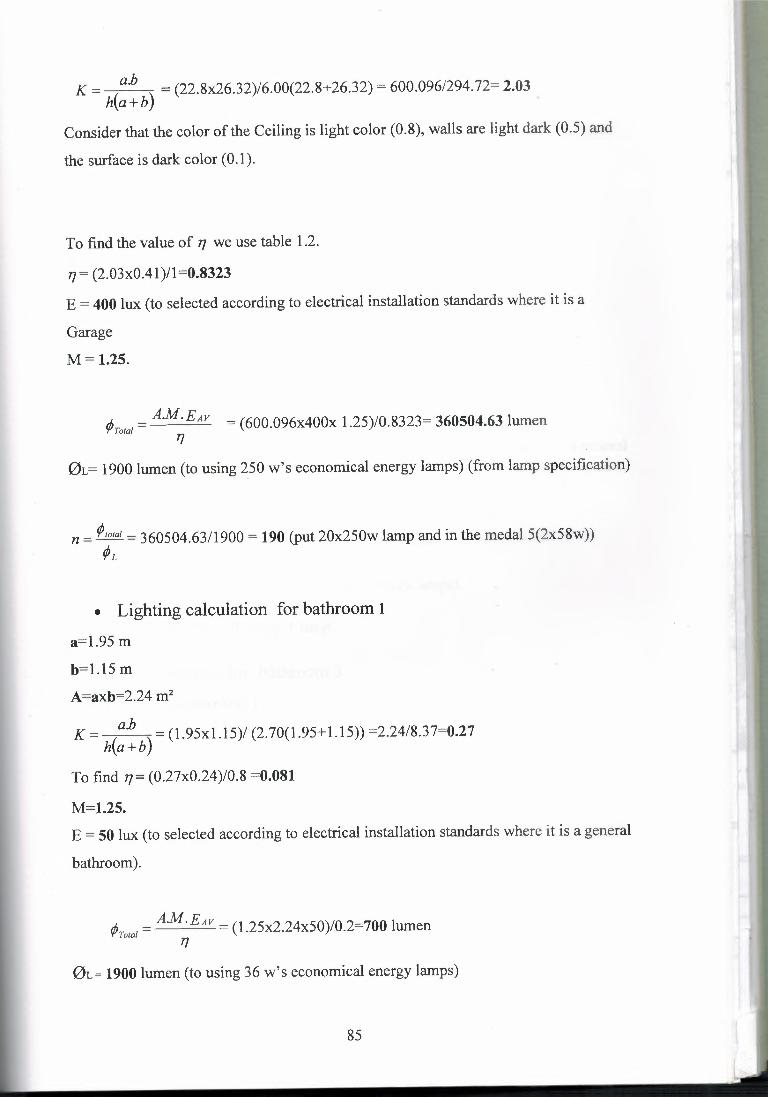
ah K = ( ) = (22.8x26.32)/6.00(22.8+26.32) = 600.096/294.72= 2.03h a+b
Consider that the color of the Ceiling is light color (0.8), walls are light dark (0.5) and
the surface is dark color (0.1 ).
To find the value of 7/ we use table 1.2.
¢rota/ = AM. EAv = (600.096x400x 1.25)/0.8323= 360504.63 lumen7/
77= (2.03x0.41)/l=0.8323
E = 400 lux (to selected according to electrical installation standards where it is a
Garage
M = 1.25.
01= 1900 lumen (to using 250 w's economical energy lamps) (from lamp specification)
n = ¢ıotaı = 360504.63/1900 = 190 (put 20x250w lamp and in the medal 5(2x58w))ÇJL
,ı, = AM.EAv = (1.25x2.24x50)/0.2=700 lumen'!'Total 7/
• Lighting calculation for bathroom 1
a=l.95 m
b=l.15 m
A=axb=2.24 m2
ah K = ( ) = (1.95xl.15)/ (2.70(1.95+ 1.15)) =2.24/8.37=0.27h a+b
To find 7/ = (0.27x0.24)/0.8 =0.081
M=l.25.
E = 50 lux (to selected according to electrical installation standards where it is a general
bathroom).
01= 1900 lumen (to using 36 w's economical energy lamps)
85

n = ¢,ota/ =700/1900=0.37 (put l lamp)¢ı
• Lighting calculation for bathroom 2
a=l.85 m
b=l.15 m
A=l.85xl.15 =2.175 m2
ah K = ( ) = (l.85xl.15)/ (2.70(1.85+1.15)) =2.175/8.1=0.27h a+b
n= (0.27x0.24)/1.25=0.052
M=l.25
To find the value of 17 we use table 1.2.
E= 50 lux (to selected according to electrical installation standards where it is a general
bathroom).
¢raıaı = A.M~EAv = (2.175xl.25x50)/0.2=/0.2=680 lumen
0L= 1900 lumen (to using 36 w's economical energy lamps).
n = ¢,aıaı = (680/1900) =0.36 put 1 lamp¢ı
Lighting calculation for bathroom 3
It's the same as bathroom 1
Lighting calculation for WC 1a= 2.75m
b = 2.03m
A=2.75x2.03=5.585 m2
ah K = ( ) = (2.75x2.03)/ (2.70(2.75+2.03)) =5.585/12.825= 0.436h a+b
86

rı= (0.436x0.24)/0.8=0.131
d=l.25
E = 50 lux (to selected according to electrical installation standards where it is a general
bathroom).
,ı, = AM.EAv = (5.585xl.25x50)/0.13=2682.7umen'!'Total T/
0L= 1900 lumen (to using 36 w's economical energy lamps).
n = ¢,oıaı = 2682.7/1900=1.41 (put 1 fluorescent lamp).¢L
Lighting calculation for WC 2
a=2.90m
b=2.03m
A= 5.89 m2
ahK = , , (2.90x2.03)/ (2.70(2.90+2.03)) = 0.442
rı= (0.442x0.24)/0.8 = 0.132
M= 1.25
E = 50 lux (to selected according to electrical installation standards where it is a general
bathroom).
¢Toıaı = A.M.EAv = (5.89xl.25x50)/0.13 = 283.17lumenT/
0L= 1900 lumen (to using 36 w's economical energy lamps).
87
n = ¢ıoıaı = (283.171/1900) = 0.149 (put 1 fluorescent lamp).¢L
Lighting calculation for container
a= 1.70 m

b = 1.60 m
A=2.72m2
a.bK = ( ) = (l.70xl.60)/ (2.70(1.70+160)) = 0.305h a+b
17= (0.305x0.24)/0.8 = 0.0915
M= 1.25E = 50 lux (to selected according to electrical installation standards where it is a general
Container)
AM.EAV¢Toıaı = = (2.72xl.25x50)/ (0.0915) = 1857.9rı
0L= 1900 lumen (to using 36 w's economical energy lamps).
n = ¢ıoıaı = (1857.9/1900) = 0.977 (put 1 wall lamp)¢ı
Lighting calculation for the corridor
a= 3.95 m
b = 1.30m
A= 5.135 m2
a.bK = ( ) = (3.95xl.30)/ (2.70(3.95+1.30)) = 2.64h a+b
17= (2.64x0.24)/0.8 = 0.792
M= 1.25E = 100 lux (to selected according to electrical installation standards where it is a
general corridor)
¢Tora/= A.M.EAv = (5.135xl.25x100)/ (0.792) = 811.2rı
0L= 1900 lumen (to using 36 w's economical energy lamps).
n = ¢ıoıaı = (811.2)/ (1900) = 0.43 149 (put 2(4x20w fluorescent lamp)¢ı
. Lighting calculation for the 1st office
a= 5.08 m
b = 3.80 m
A= 19.30 m2
88

n = </ı,oıaı = (7658730.1)/1900 = 40.30 (put 2(2x58w fluorescent lamp)¢ı
Lighting calculation for the reception
a=7.18m
b = 3.90 m
A= 28.0 m2
ah K = ( ) = (7.18x3.90)/ (2.70(7.18+3.90)) = 0.935h a+b
ah K = ( ) = (5.08x3.80)/ (2.70(5.08+3.80)) = 0.211h a+b
rı= (0.21 lx0.24)/0.8 = 0.063
M= 1.25
E =200 lux (to selected according to electrical installation standards where it is general
for offices)
¢rota/= A.M.EAv = (19.30xl.25.200)/0.063 = 7658730. 11]
0L= 1900 lumen (to using 36 w's economical energy lamps).
E =200 lux (to selected according to electrical installation standards where it is general
for receptions)
</Jroıaı = A.M.EAv = (28.0xl.25x200)/ (0.280) = 87501]
rı= (0.935x0.24)/0.8 = 0.280
M= 1.25
0L= 1900 lumen (to using 36 w's economical energy lamps).
89
n = </ı,oıaı = (8750)/ (1900) = 4.60 (put 2(2x58w fluorescent lamp)</Jı,
Lighting calculation for the 2nd corridor
a=3.80m
b = 2.08 m
A= 7.90 m2
ah K = ( ) = (3.80x2.08) (2.70(3.80+2.08)) = 0.489h a+b

rı= (0.489x0.24)/0.8 = 0.149
M= 1.25
E = 100 lux (to selected according to electrical installation standards where it is a
general corridor)
,ı. A.M.EAv ( I 6'rTotal = = 7.90xl.25x100) 0.149 = 627.57J
rı= (0.21 lx0.24)/0.8 = 0.063
M= 1.25
0L= 1900 lumen (to using 36 w's economical energy lamps).
n = ¢,oıaı = (6627 .5)/ (1900) = 3 .48(put 2(4x20w fluorescent lamp)¢ı
Lighting calculation for the 2nd office
a=5.08m
b = 3.80 m
A= 19.30 m2
ahK = ( ) = (5.08x3.80)/ (2.70(5.08+3.80)) = 0.211h a+b
E =200 lux (to selected according to electrical installation standards where it is general
for offices)
A.M.EAv )/ 6 8 1</Jro,aı = = (19.30xl.25.200 0.063 = 7 5 730.7J
0L= 1900 lumen (to using 36 w's economical energy lamps).
n = ¢,oıaı = (7658730.1)/1900 = 40.30 (put 2(2x58w fluorescent lamp)¢ı
1. VOLTAGE CALCULATION FORMULA
• For three phase (220/380 v)
t:[%]= 100xLxP = LxP(KW)xl05
zxqxv2 56xqx(380)2
Lxpe % = 0.0124-- < 1.5q
90

• For one phase (220 v)
ı-[%] = 200xLxP = 2.l05xLxP(KW)xx q x v2 56 x q x c220)2
Lxpe % = 0.074-- < 1.5q
Where
ı-[%] = voltage calculation (percent)
P = power (KW),
L = distance of the line (m),
V = voltage (380 volt) in 3 phase and (220) in one phase.
q = conductive cross section (mm2)
x = conductive coefficient where x (cu) =56 ml Omm2, x (Al) =35m/Omm2
2. CURRENT CALCULATION FORMULA
• For three phase
1= pVxCOS¢xJ3
• For one phase
I= pVxCOS¢
Where
V = voltage (380 volt) in 3 phase and (220) in one phase.
P = power (KW),
I = current.
Calculating the voltage drop
!). uTOT = g X L X I
91

I ® I :~:~nuJ DT1 I I ~OHNE
L=5ın
2x2.5 ınxn2
St), = g1 x Lıx 11 =2.6X8~60=1248mV
~U2 = s,» L_2x_]ı =1.6X5Xl2.5=100mV
The total is Ul +U2=1248+100=1348mv=l.348 V
The total power will be calculated by P=VXI ....the power is shown in the graphs
for each line so by adding all the power of each line we get the total power.
The power in the first floor is 15452wand in the ground floor is 21808 w so thetotal is 3 7260 W
92

Table 1.2: Table of Efficiency
K= 0.60 1}= 0.23 0.18 0.18 0.20 0.19 o.ıs o.ıs 0.12 o.ıs
0.24
0.80 0.31 0.29 0.24 0.23 0.25 0.24 0.20 0.19 0.16 0.17
1.00 0.36 0.33 0.29 0.28 0.29 0.28 0.24 0.23 0.20 0.20
1.25 0.41 0.38 0.34 0.32 0.33 0.31 0.28 0.27 0.24 0.24
1.50 0.45 0.41 0.38 0.36 0.36 0.34 0.32 0.30 0.27 0.26
2.00 0.51 0.46 0.45 0.41 0.41 0.38 0.37 0.35 0.31 0.30
2.50 0.56 0.49 o.so 0.45 0.45 0.41 0.41 0.38 0.35 0.34
3.00 0.59 0.52 0.54 0.48 0.47 0.43 0.43 0.40 0.38 0.36
4.00 0.63 0.55 0.58 0.51 o.so 0.47 0.47 0.44 0.41 0.39
5.00 0.66 0.57 0.62 0.54 0.53 o.so o.so 0.46 0.44 0.40
Table 1.3: The colors percentage
0.80 0.50 0.30
Ceiling
Wall o.so 0.30 o.so 0.30 0.10 0.30
0.30 0.10 0.30 0.10 0.30 0.10 0.30 0.10 0.30 0.10
Ground
---- --

~o1
2x1<·1mm2 pyç 2(1x36W) FLO+ 2(100W) LAMBA LH1(1x13A) PRiZ RADYALSEMAVER 6000W PH
YEDEK S
LDPDKP 2x40A
lth=100mA
...._ - <,1x36WMUTFAKlf2x36;-
LG LG1x36LF
1x36WLH
WQ ısn l so bsl ıoo bsl aa.o Wl~
am
ZEMiN KAT ELEKTRİK PLA~1\

----------, IIIII
3x250A MCCB
'ADT----,I (ANA DAGITIM) II IIIIII
3x250A MCCB
2x10+6mm2 PVC
R OTI
15 kA1x40AMCCB
15 kA IOT
'.x70r'JW<L_
=III
I II I
~-ı L ıF IL--- _] I-------------- ...ıl-
15 kA3x63A MCCB
RS~OTI15 kA
YED~
YEDEK
1x7~
, MERKEZ\ TOPRAKLAMAr·-·-ı-·-·ı R<10HM
1x70mm21 1x70mrn2i 1x70mmd~ "'=='" -===-
or,I
a
-- I
IDT1---,I """' .. -· ·-
RS II 3x1 BOA MCCB ax100A ,ı, , •• , ·--00,
- RS
lı' II ........ .. -· - IRS I
o-- . ~4~ ___ _J
j
I
-

KTMMOBELEKTRİK MÜHENDİSLERİ ODASI
ELEKTRİK TESİSATLAR! ASGARİ BİRİM FİYAT LİSTELERİ
•... -....... ·-· ....... . - .. -----
Birim Fiyat YAPILACAK iŞİN TANIMIBiRiM FiYAT ADET TOPLAM
No: /YTL)A Bina içi Proiöktör tesisatı:( 500 W'a kadar\ 141,00 12 1692A-1 1x40 W Floresent Tesisatı: 78,00 11 858A-2 1x65/80W Floresent Tesisatı: 91,75 4 367A-3A-4 2x40 W Floresent Tesisatı: 106,15 7 743,05
A-5 2x65/80W Floresent Tesisatı: 126,75 14 1774,5A-5.1 Petek DiffUserll 4x20 W S/UstU Floresent Lamba tesisatı: 302,50 22 6655A-6 125 W cıva buharlı lamba tesisatı 179,50 6 1077A-7A-8A-8.1 250 W Sodyum buharlı lamba tesisatı 417,25 24 10014A-9 1x13 Amo. Priz tesisatıA-10 2x13 Amo. Priz tesisatı. 56,00 35 1960A-11 67,00 55 3685
A-12 Klima IAlr Condition) tesisatı lsolit unit\ 99,00 19 1881A-12.1 Kaoı otomatiği tesisatı: 155,75 2 311,5A-12.2 MCCB Kesiciler: (Ölçü: Adet\A.12.3 MCCB 1x63 Amo.'e kadar 246,25 13 TL 3201,25A.12.4 MCCB 1x100 Amo.'e kadar 310,00 2 TL 620A.12.5A.12.6
MCCB 3x160 Amoer. 565,00 2 TL 1130A.13A.13.1 MCCB 3x250 Amoer. 1175,00 4 TL 4700A.13.2 UÇ FAZ KOLLU SIGORTALI KESiCiLER: (OlçU:AdetlA.13.3 3x16ı Amoer Kollu Siaortalı Kesici Tesisatı: 212,00 19 '4028A.13.4 3x15) Amoer Kollu Siaortalı Kesici Tesisatı: 220,00 9 1980A.13.5 13x20\ Amper Kollu Sigortalı Kesici Tesisatı: 226,00 39 8814A.13.6 il3x30\ Amper Kollu Siaortalı Kesici Tesisatı: 268,00 17 4556A.13.7A.13.8 tesisat bedeli : 60.047,30A.13.9 mühendislikhizmetleriücreti ( %13): 7.806,15A.13.10 proje hizmetleriücreti ( %70 ) : 5.464,30A.13.11 kontrollukhizmetleriücreti ( %30 ) : 2.341,84

Term
Accent Lighting
Absorption
Accommodation
Adaptation
Alternating Current (AC)
Ambient Lighting
Amperes (amps or A)
Back Lighting
Baffle
Ballast
"Batwing" Distribution
Candela
Candlepower
Candlepower Distribution Curve
Cavity Ratio
Lighting Glossary
Definition
Directional lighting to emphasize a particular object or to drawattention to a part of the field of view.
The dissipation of light within a surface or medium.
The process by which the eye changes focus from one distanceto another.The process by which the visual system becomes accustomed tomore or less light than it was exposed to during an immediatelypreceding period. It results in a change in the sensitivity of theeye to light.Flow of electricity which cycles or alternates direction manytimes per second. The number of cycles per second is referredto as frequency. Most common frequency used in this country is60 Hertz (cycles per second).
Background or fill light in a space.
The unit of measurement of electric current.
The illumination provided for scenery in off-stage areas visibleto the audience.An opaque or translucent element that serves to shield a lightsource from direct view at certain angles, or serves to absorbunwanted light.An auxiliary device consisting of induction windings woundaround a metal core and sometimes includes a capacitor forpower correction. It is used with fluorescent and HID lamps toprovide the necessary starting voltage and to limit the currentduring operation.Candlepower and distribution which serves to reduce glare andveiling reflections by having its maximum output in the 30° to60° zone.The unit of measurement of luminous intensity of a light sourcein a given direction.Luminous intensity expressed in candelas.
A curve, generally polar, representing the variation ofluminousintensity of a lamp or luminaire in a plane through the lightcenter.A number indicating cavity proportions calculated from length,
1

width and height.
Contains a thermal protective device which deactivates theballast when the case reaches a certain critical temperature. Thedevice resets automatically when the case temperature drops toa lower temperature.
The ratio of the luminous flux (lumens) from a luminarycalculated as received on the work-plane to the luminous fluxemitted by the luminaries lamps alone.
Cold Cathode Lamp An electric-discharge lamp whose mode of operation is that of aflow discharge.
Class "P" Ballast
Coefficient ofUtilization (CU)
Colorimetry
Color RenderingIndex (CRI)
Color Temperature
Cone Reflector
Contrast
Cool Beam Lamps
Cove Lighting
Cutoff Luminaires
Digital AddressableLighting Interface(DALI)
Dimming Ballast
Direct Current (DC)
Direct Lighting
Direct Glare
The measurement of color.
Measure of the degree of color shift objects undergo whenilluminated by the light source as compared with the color ofthose same objects when illuminated by a reference source ofcomparable color temperature.
The absolute temperature of a blackbody radiator having achromaticity equal to that of the light source.
Parabolic reflector that directs light downward therebyeliminating brightness at high angles.
The difference in brightness (luminance) of an object and itsbackground.Incandescent PAR lamps that use a special coating (dichroicinterference filter) on the reflectorized potion of the bulb toallow heat to pass out the back while reflecting only visibleenergy to the task, thereby providing a "cool beam'' oflight.
Lighting comprising sources sheilded by a ledge or horizontalrecess, and distributing light over the ceiling and upper wall.
Outdoor luminaires that restrict all light output to below 85°from vertical.An open communications protocol used by multiple control andballast manufacturers for digital control.
Special fluorescent lamp ballast, which when used with adimmer control, permits varying light output.
Flow of electricity continuously in one direction from positiveto negative.Lighting involving luminaires that distribute 90 to 100% ofemmited light in the general direction of the surface to beilluminated. The term usually refers to light emitted in adownward direction.Glare resulting from high luminances or insufficiently shielded
2

light sources in the field of view. It usually is associated withbright areas, such as luminaires, ceilings and windows whichare outside the visual tasks or region being viewed.
A lamp in which light (or radiant energy near the visiblespectrum) is produced by the passage of an electric currentthrough a vapor or a gas.
Glare producing discomfort. It does not necessarily interferewith visual performance or visibility.
Emergency Lighting Lighting system designed to provide minimum illuminationrequired for safety, during power failures.
Discharge Lamp
Discomfort Glare
Efficacy
Efficiency
Equivalent SphereIllumination (ESi)
"ER" (EllipticalReflector)
Extended LifeLamps
Fill Light
Floodlighting
Fluorescent Lamp
Footcandle (fc)
Foot Lambert (fl)
Footlights
General Lighting
General ServiceLamps
Glare
See Lamp Efficacy.
See Luminaire Efficiency.
The level of sphere illumination which would produce taskvisibility equivalent to that produced by a specific lightingenvironment.
Lamp whose reflector focuses the light about 2" ahead of thebulb, reducing light loss when used in deep baffie downlights.
Incandescent lamps that have an average rated life of2500 ormore hours and reduced light output compared to standardgeneral service lamps of the same wattage.
Illumination added to reduce shadows or contrast range.
A system designed for lighting a scene or object to a luminancegreater than its surroundings. It may be for utility, advertising ordecorative purposes.
A low-pressure mercury electric-discharge lamp in which aphosphor coating transforms some of the ultraviolet energygenerated by the discharge into light.
The unit of illuminance when the foot is taken as the unit oflength. It is the illuminance on a surface one square foot in areaon which there is a uniformly distributed flux of one lumen.
A unit of luminance of perfectly diffusing surface emitting orreflecting light at the rate of one lumen per square foot.
A set of strip lights at the front edge of the stage plateform usedto soften face·shadows cast by overhead luminaires and to addgeneral toning lighting from below.
See Ambient Lighting.
"A" or "PS" incandescent lamps.
The sensation produced by luminance within the visual fieldthat is sufficiently greater than the luminance to which the eyes
3

Ground Relamping
High IntensityDischarge (HID)Lamp
High OutputFluorescent Lamp
are adapted to cause annoyance, discomfort, or loss in visualperformance and visibility.
Relamping of a group of luminaires at one time or reducerelamping labor costs.
A discharge lamp in which the light producing arc is stabilizedby wall temperature, and the arc tube has a bulb wall loading inexcess of three watts per square centimeter. HID lamps includegroups oflamps known as mercury, metal halide, and highpressure sodium.
Operates at 800 or more milliamperes for higher light outputthan standard fluorescent lamp (430MA).
High Pressure High intensity discharge (HID) lamp in which light is producedSodium (HPS) Lamp by radiation from sodium vapor. Includes clear and diffuse
coated lamps.
Incandescence
Incandescent Lamp
Instant StartFluorescent Lamp
Inverse Square Law
Kelvin
Kilowatt-Hour(KWH)
Lamp
Lamp Efficacy
Lamp LumenDepreciation (LLD)
Light
Lens
Local Lighting
The self-emission of radiant energy in the visible spectrum dueto the thermal excitation of atoms or molecules.
A lamp in which light is produced by a filament heated toincandescence by an electric current.
A fluorescent lamp designed for starting by a high voltagewithout preheating of the electrodes.
The law stating that the illuminance at a point on a surfacevaries directly with the intensity of a point source, and inverselyas the square of the distance between the source and the point. Ifthe surface at the point is normal to the direction of the incidentlight, the law is expressed by fc=cp/d2.
Unit of measurement for color temperature. The Kelvin scalestarts from absolute zero, which is -273° Celsius.
Unit of electrical power consumed over a period of time. KWH= watts/1000 x hours used.
An artificial source of light (also portable luminaire equippedwith a cord and plug).
The ratio of lumens produced by a lamp to the watts consumed.Expressed as lumens per watt (LPW).
Multiplier factor in illumination calculations for reduction in thelight output of a lamp over a period of time.
Radiant energy that is capable of exciting the retina andproducing a visual sensation. The visible portion of theelectromagnetic spectrum extends from about 380 to 770 nm.
Used in luminaires to redirect light into useful zones.
Lighting designed to provide illuminance over a relatively smallarea or confined space without providing any significant general
4

Louver
Long Life Lamps
Low Pressure Sodium Lamp
Low Voltage Lamps
Lumen
Luminaire
Luminaire Direct Depreciation (LDD)
Luminaire Efficiency
Luminance
Lux
Maintenance Factor (MF)
Mercury Lamp
Metal Halide Lamp
Nadir
Overall Length (OAL)
surrounding lighting.A series of baffles used to shield a source from view at certainangles or to absorb unwanted light. The baffles usually arearranged in a geometric pattern.
See Extended Life Lamps.A discharge lamp in which light is produced by radiation ofsodium vapor at low pressure producing a single wavelength ofvisible energy, i.e. yellow.
Incandescent lamps that operate at 6 to 12 volts.
The unit ofluminous flux. It is the luminous flux emitted withina unit solid angle (one steradian) by a point source having auniform luminous intensity of one candela.A complete lighting unit consisting of a lamp or lamps togetherwith the parts designed to distribute the light, to position andprotect the lamps and to connect the lamps to the power supply.
The multiplier to be used in illuminance provided by clean, newluminaires to the reduced illuminance that they will provide dueto direct collection on the luminaires at the time at which it isanticipated that cleaning procedures will be instituted.
The ratio ofluminous flux (lumens) emitted by a luminaire tothat emitted by the lamp or lamps used.The amount of light reflected or transmitted by an object.
The metric unit of illuminance. One lux is one lumen per squaremeter (lm/m2).A factor used in calculating illuminance after a given period oftime and under given conditions. It takes into accounttemperature and voltage variations, dirt accumulation onluminaire and room surfaces, lamp depreciation, maintenanceprocedures and atmosphere conditions.A high intensity discharge (HID) lamp in which the majorportion of the light is produced by radiation from mercury.Includes, clear, phosphor-coated and self-ballasted lamps.
A high intensity discharge (HID) lamp in which the majorportion of the light is produced by radiation of metal halides andtheir products of dissociation-possible in combination withmetallic vapors such as mercury. Includes clear and phosphorcoated lamps.Vertically downward directly below the luminaire or lamp;designated as 0°.Maximum overall length of a light fixture.
5

"PAR" Lamps Parabolic aluminized reflector lamps which offer excellentbeam control, come in a variety of beam patterns from verynarrow spot to wide flood and can be used outdoors unprotectedbecause they are made of "hard" glass that can withstandadverse weather.
Photometry
A grid of baffles which redirect light downward and providevery low luminaire brightness.
The measurement of light quantities.
Parabolic Louvers
Point Method A lighting design procedure for predetermining the illuminanceLighting Calculation at various locations in lighting installations, by use of luminaire
photometric data.
Reflector
The process by which the transverse vibrations of light wavesare oriented in a specific plane. Polarization may be obtained byusing either transmitting or reflecting media.
Ratio of: Watts (volts x amperes) Power factor in lighting isprimarily applicable to ballasts. Since volts and watts areusually fixed, amperes (or current) will go up as power factorgoes down. This necessitates the use of larger wire sizes tocarry the increased amount of current needed with Lowe PowerFactor (L.P.F) ballasts. The addition of a capacitor to an L.P .F.ballast converts it to a H.P .F. ballast.A fluorescent lamp designed for operation in a circuit requiringa manual or automatic starting switch to preheat the electrode inorder to start the arc.Reflectorized lamps available in spot (clear face) and flood(frosted face).A fluorescent lamp designed for operation with a ballast thatprovides a low-voltage winding for preheating the electrodesand initiating the arc without a starting switch or the applicationof high voltage.
See Footcandles.Light bouncing off a surface. In specular reflection the lightstrikes and leaves a surface at the same angle. Diffuse reflectedlight leaves a surface in all directions.Sometimes called reflectance factor. The ratio of reflected lightto incident light (light falling on a surface). Reflectance isgenerally expressed in percent.Glare resulting from specular reflections of high luminances inpolished or glossy surfaces in the field of view. It usually isassociated with reflections from within a visual task or areas inclose proximity to the region being viewed.
A device used to redirect the light flow from a source bybouncing it off the surface.
Polarization
Power Factor
Preheat Fluorescent Lamp
"R" Lamps
Rapid Start Fluorescent Lamp
Raw Footcandles
Reflection
Reflectance
Reflected Glare
6

The process by which the direction of a ray of light changes asit passes obliquely from one medium to another in which itsspeed is different.
Room Cavity Ration A number indicating room cavity proportions calculated from(RCR) length, width and height.
Refraction
Rough ServiceLamps
Self-ballastedMercury Lamps
Silver Bowl Lamps
Spacing Ratio
Incandescent lamps designed with extra filament supports towithstand bumps, shocks and vibrations with some loss inlumen output.
Any mercury lamp of which the current-limiting device is anintegral part.
Incandescent "A" lamps with a silver finish inside the bowl orportion of the bulb. Used for indirect lighting.
Ratio of the distance between luminaire centers to the mountingheight above the work-plane for uniform illumination.
A plot of the level of energy at each wavelength of a lightsource.
Spectral EnergyDistribution (SED)Curves
Sphere Illumination The illumination on a task from a source providing equalluminance in all directions about that task, such as anilluminated sphere with the task located at the center.
Surface MountedLuminaire
Suspended(Pendant)Luminaire
Task Lighting
Three-Way Lamps
Transformer
Transmission
Tungsten-HalogenLamp
Veiling Reflections
Vibration ServiceLamps
A luminaire that is mounted directly on a ceiling.
A luminaire that is hung from a ceiling by supports.
Lighting directed to a specific surface or area that providesillumination for visual tasks.
Incandescent lamps that have two separately switched filamentspermitting a choice of three levels or light such as 30/70/100,50/100/150 or 100/200/300 watts. They can only be used in abase down position.
A device to raise or lower electric voltage.
The passage of light through a material.
A gas filled tungsten incandescent lamp containing a certainproportion of halogens.
Regular reflections superimposed upon diffuse reflections froman object that partially or totally obscure the details to be seenby reducing the contrast. This is sometimes called reflectedglare.
See Rough Service Lamps.
7

Visual Edge
The rating of a lighting system expressed as a percent of peoplewho, when viewing from the specified location and in aspecified direction, will be expected to find it acceptable interms of discomfort glare.The line on a isolux chart which has a value equal to 10% of themaximum illumination.
Visual Comfort Probability (VCP)
Visual Field The field of view that can be perceived when the head and eyesare kept fixed.
Wall Wash Lighting A smooth even distribution of light over a wall.
Zonal Cavity Method Lighting Calculation
The unit for measuring electric power. It defines the power orenergy consumed by an electrical device. The cost of operatingan electrical device is determined by the watts it consumestimes the hours or use. It is related to volts and amps by thefollowing formula: Watts= Volts x Amps.
A lighting design procedure used for predetermining therelation between the number and types of lamps or luminaires,the room characteristics, and the average illuminance on thework-plane. It takes into account both direct and reflected flux.
Watt(W)
8

CONCLUSION
In a distributions boxes that we using in our plan three phases because the number of the
socket outlets circuits and the lighting circuits is more than the parameter cause the
maximum number of single phase (lxl2). The distributions types are commonly used in our
plan domestic, commercial and light industrial applications for low voltage (less than
1000V) use. MCB - Miniature Circuit Breaker - rated current not more than lOOA, and
MCCB - Moulded Case Circuit Breaker - rated current up to 1 OOOA.
A conductor is a material which offers a low resistance to a flow of current. For example
silver is better than copper but it is too expensive for practical purposes. Electrical
conductors are usually made of copper, although aluminium is being used to a greater
extent, particularly as the price of copper increases. The copper wire is then dipped into a
tank containing molten tin. This done for two reasons: (a) to protect the copper if the wire is
to be insulated with vulcanized rubber, as this contains sulphur which attacks the copper;
and (b) to make the copper conductor easier to solder.
P.V.C. insulated copper and aluminium cables are gradually replacing this cables, expect in
conditions where creosote is present as this attacks the p.v.c. insulation.
It is essential for the correct operation of the E L C B that the earth and frame connections
are not reversed. A reversal of connection places voltage between the frame and the general
mass of earth when the test button is pressed.
The fuses must be capable of protecting the smallest conductor in the circuit.
All fuses and switches must place in the conductor and metal lampholders must be earthed
and the phase conductors should be terminated at the centre pin of Giant Edison Screw
(G.E.S.) lampholders.
The 2- metre rule. In conditions where two separate phases (for example the red and blue
phases) are brought into the same room:
(a) The controlling switch must be clearly marked 415 Volts.
(b) Switches and sockets outlets supplied from different phases must be placed at least 2
metres apart. This is particularly important where portable appliances are used. It
avoids the danger of a voltage of 415 V appearing between appliances or switches
which can be touched simultaneously.

The purpose of the ring circuit (a) to minimize trailing flexes. (b) To take advantages of the
fact that all outlets in a domestic installation are not operated simultaneously this known as
the diversity in an installation.
Ceiling roses must not used on circuits operating above 250 V and no more than one
flexible cord is permitted from any one ceiling rose. The earthing terminal of every ceiling
rose must be connected to the earth continuity conductor of the final sub-circuit.
The greatest care should be taken to protect temporary installation against mechanical
damage and portable appliances (for example, drills) should be regularly checked. Low
voltage (e.g. 11 O V) step-down transformers should be used wherever possible. To
minimize the danger from the shock.
2
ılI

REFERENCES
[1] Electrical installation Theory and practice, by E. L Donnelly, March 21, 1994.
[2]. Advanced Electrical Installations, by C. Shelton, March 1, 1996.
[3]. Illumination (Electıical Installation Series), by E.G. Patterson, December 1995.
[4] lee 16th Edition Wiring Regulations: Inspection, Testing and Certification (Electrical
Installation Handbooks) by Brian Scaddan, B. Scaddan, March 1, 1998.
[5] Electrical Installation Calculations, by A.J. Watkins, Russell K. Parton.
[6] www.diydoctor.org. uk/home.htm
[7] www.lighting.org
[8] www.rfı_ihd.corn.au/download
[9] www.google.coın/electrical installation
105