fail-open unit for mcafee secure gateway appliances ... guide fail-open unit for mcafee® secure...
TRANSCRIPT

Product Guide
Fail-Open Unit for McAfee® Secure Gateway Appliances
McAfee® Network ProtectionIndustry-leading intrusion prevention solutions


Product Guide
Fail-Open Unitfor McAfee® Secure Gateway Appliances
McAfee® Network ProtectionIndustry-leading intrusion prevention solutions

COPYRIGHTCopyright © 2006 McAfee, Inc. All Rights Reserved. No part of this publication may be reproduced, transmitted, transcribed, stored in a retrieval system, or translated into any language in any form or by any means without the written permission of McAfee, Inc., or its suppliers or affiliate companies.
TRADEMARK ATTRIBUTIONSACTIVE FIREWALL, ACTIVE SECURITY, ACTIVESECURITY (AND IN KATAKANA), ACTIVESHIELD, CLEAN-UP, DESIGN (STYLIZED E), DESIGN (STYLIZED N), ENTERCEPT, EPOLICY ORCHESTRATOR, FIRST AID, FOUNDSTONE, GROUPSHIELD, GROUPSHIELD (AND IN KATAKANA), INTRUSHIELD, INTRUSION PREVENTION THROUGH INNOVATION, MCAFEE, MCAFEE (AND IN KATAKANA), MCAFEE AND DESIGN, MCAFEE.COM, MCAFEE VIRUSSCAN, NET TOOLS, NET TOOLS (AND IN KATAKANA), NETSCAN, NETSHIELD, NUTS & BOLTS, OIL CHANGE, PRIMESUPPORT, SPAMKILLER, THREATSCAN, TOTAL VIRUS DEFENSE, VIREX, VIRUS FORUM, VIRUSCAN, VIRUSSCAN, VIRUSSCAN (AND IN KATAKANA), WEBSCAN, WEBSHIELD, WEBSHIELD (AND IN KATAKANA) are registered trademarks or trademarks of McAfee, Inc. and/or its affiliates in the US and/or other countries. The color red in connection with security is distinctive of McAfee brand products. All other registered and unregistered trademarks herein are the sole property of their respective owners.
LICENSE INFORMATIONLicense AgreementNOTICE TO ALL USERS: CAREFULLY READ THE APPROPRIATE LEGAL AGREEMENT CORRESPONDING TO THE LICENSE YOU PURCHASED, WHICH SETS FORTH THE GENERAL TERMS AND CONDITIONS FOR THE USE OF THE LICENSED SOFTWARE. IF YOU DO NOT KNOW WHICH TYPE OF LICENSE YOU HAVE ACQUIRED, PLEASE CONSULT THE SALES AND OTHER RELATED LICENSE GRANT OR PURCHASE ORDER DOCUMENTS THAT ACCOMPANIES YOUR SOFTWARE PACKAGING OR THAT YOU HAVE RECEIVED SEPARATELY AS PART OF THE PURCHASE (AS A BOOKLET, A FILE ON THE PRODUCT CD, OR A FILE AVAILABLE ON THE WEB SITE FROM WHICH YOU DOWNLOADED THE SOFTWARE PACKAGE). IF YOU DO NOT AGREE TO ALL OF THE TERMS SET FORTH IN THE AGREEMENT, DO NOT INSTALL THE SOFTWARE. IF APPLICABLE, YOU MAY RETURN THE PRODUCT TO MCAFEE OR THE PLACE OF PURCHASE FOR A FULL REFUND.
Attributions This product includes or may include:• Software developed by the OpenSSL Project for use in the OpenSSL Toolkit (http://www.openssl.org/). • Cryptographic software written by Eric A. Young and software written by Tim J. Hudson. • Some software programs that are licensed (or sublicensed) to the user under the GNU General Public License (GPL) or other similar Free Software licenses which, among other rights, permit the user to copy, modify and redistribute certain programs, or portions thereof, and have access to the source code. The GPL requires that for any software covered under the GPL which is distributed to someone in an executable binary format, that the source code also be made available to those users. For any such software covered under the GPL, the source code is made available on this CD. If any Free Software licenses require that McAfee provide rights to use, copy or modify a software program that are broader than the rights granted in this agreement, then such rights shall take precedence over the rights and restrictions herein. • Software originally written by Henry Spencer, Copyright 1992, 1993, 1994, 1997 Henry Spencer. • Software originally written by Robert Nordier, Copyright © 1996-7 Robert Nordier. • Software written by Douglas W. Sauder. • Software developed by the Apache Software Foundation (http://www.apache.org/). A copy of the license agreement for this software can be found at www.apache.org/licenses/LICENSE-2.0.txt. • International Components for Unicode ("ICU") Copyright ©1995-2002 International Business Machines Corporation and others. • Software developed by CrystalClear Software, Inc., Copyright ©2000 CrystalClear Software, Inc. • FEAD® Optimizer® technology, Copyright Netopsystems AG, Berlin, Germany. • Outside In® Viewer Technology ©1992-2001 Stellent Chicago, Inc. and/or Outside In® HTML Export, © 2001 Stellent Chicago, Inc. • Software copyrighted by Thai Open Source Software Center Ltd. and Clark Cooper, © 1998, 1999, 2000. • Software copyrighted by Expat maintainers. • Software copyrighted by The Regents of the University of California, © 1996, 1989, 1998-2000. • Software copyrighted by Gunnar Ritter. • Software copyrighted by Sun Microsystems, Inc., 4150 Network Circle, Santa Clara, California 95054, U.S.A., © 2003. • Software copyrighted by Gisle Aas. © 1995-2003. • Software copyrighted by Michael A. Chase, © 1999-2000. • Software copyrighted by Neil Winton, ©1995-1996. • Software copyrighted by RSA Data Security, Inc., © 1990-1992. • Software copyrighted by Sean M. Burke, © 1999, 2000. • Software copyrighted by Martijn Koster, © 1995. • Software copyrighted by Brad Appleton, © 1996-1999. • Software copyrighted by Michael G. Schwern, ©2001. • Software copyrighted by Graham Barr, © 1998. • Software copyrighted by Larry Wall and Clark Cooper, © 1998-2000. • Software copyrighted by Frodo Looijaard, © 1997. • Software copyrighted by the Python Software Foundation, Copyright © 2001, 2002, 2003. A copy of the license agreement for this software can be found at www.python.org. • Software copyrighted by Beman Dawes, © 1994-1999, 2002. • Software written by Andrew Lumsdaine, Lie-Quan Lee, Jeremy G. Siek © 1997-2000 University of Notre Dame. • Software copyrighted by Simone Bordet & Marco Cravero, © 2002. • Software copyrighted by Stephen Purcell, © 2001. • Software developed by the Indiana University Extreme! Lab (http://www.extreme.indiana.edu/). • Software copyrighted by International Business Machines Corporation and others, © 1995-2003. • Software developed by the University of California, Berkeley and its contributors. • Software developed by Ralf S. Engelschall <[email protected]> for use in the mod_ssl project (http:// www.modssl.org/). • Software copyrighted by Kevlin Henney, © 2000-2002. • Software copyrighted by Peter Dimov and Multi Media Ltd. © 2001, 2002. • Software copyrighted by David Abrahams, © 2001, 2002. See http://www.boost.org/libs/bind/bind.html for documentation. • Software copyrighted by Steve Cleary, Beman Dawes, Howard Hinnant & John Maddock, © 2000. • Software copyrighted by Boost.org, © 1999-2002. • Software copyrighted by Nicolai M. Josuttis, © 1999. • Software copyrighted by Jeremy Siek, © 1999-2001. • Software copyrighted by Daryle Walker, © 2001. • Software copyrighted by Chuck Allison and Jeremy Siek, © 2001, 2002. • Software copyrighted by Samuel Krempp, © 2001. See http://www.boost.org for updates, documentation, and revision history. • Software copyrighted by Doug Gregor ([email protected]), © 2001, 2002. • Software copyrighted by Cadenza New Zealand Ltd., © 2000. • Software copyrighted by Jens Maurer, ©2000, 2001. • Software copyrighted by Jaakko Järvi ([email protected]), ©1999, 2000. • Software copyrighted by Ronald Garcia, © 2002. • Software copyrighted by David Abrahams, Jeremy Siek, and Daryle Walker, ©1999-2001. • Software copyrighted by Stephen Cleary ([email protected]), ©2000. • Software copyrighted by Housemarque Oy <http://www.housemarque.com>, © 2001. • Software copyrighted by Paul Moore, © 1999. • Software copyrighted by Dr. John Maddock, © 1998-2002. • Software copyrighted by Greg Colvin and Beman Dawes, © 1998, 1999. • Software copyrighted by Peter Dimov, © 2001, 2002. • Software copyrighted by Jeremy Siek and John R. Bandela, © 2001. • Software copyrighted by Joerg Walter and Mathias Koch, © 2000-2002. • Software copyrighted by Carnegie Mellon University © 1989, 1991, 1992. • Software copyrighted by Cambridge Broadband Ltd., © 2001-2003. • Software copyrighted by Sparta, Inc., © 2003-2004. • Software copyrighted by Cisco, Inc. and Information Network Center of Beijing University of Posts and Telecommunications, © 2004. • Software copyrighted by Simon Josefsson, © 2003. • Software copyrighted by Thomas Jacob, © 2003-2004. • Software copyrighted by Advanced Software Engineering Limited, © 2004. • Software copyrighted by Todd C. Miller, © 1998. • Software copyrighted by The Regents of the University of California, © 1990, 1993, with code derived from software contributed to Berkeley by Chris Torek.
PATENT INFORMATIONProtected by US Patents 6,496,875; 6,499,109; 6,513,122; 6,668,289; 6,728,885; 6,732,157; 6,772,345.
Issued June 2006 / Fail-Open Unit DBN-013-EN

5
Contents
1 Introducing the Fail-Open Unit 7
Product features . . . . . . . . . . . . . . . . . . . . . . . . . . . . . . . . . . . . . . . . . . . . . . . . . . . 7Detecting appliance failure . . . . . . . . . . . . . . . . . . . . . . . . . . . . . . . . . . . . . . . . 9
Using this guide . . . . . . . . . . . . . . . . . . . . . . . . . . . . . . . . . . . . . . . . . . . . . . . . . . 10Audience . . . . . . . . . . . . . . . . . . . . . . . . . . . . . . . . . . . . . . . . . . . . . . . . . . . . 10Conventions . . . . . . . . . . . . . . . . . . . . . . . . . . . . . . . . . . . . . . . . . . . . . . . . . . 11
Getting product information . . . . . . . . . . . . . . . . . . . . . . . . . . . . . . . . . . . . . . . . . 12Additional documentation for the appliance . . . . . . . . . . . . . . . . . . . . . . . . . . 12
Contact information . . . . . . . . . . . . . . . . . . . . . . . . . . . . . . . . . . . . . . . . . . . . . . . 13
2 Installing the Fail-Open Unit 15
Checking the contents of the box . . . . . . . . . . . . . . . . . . . . . . . . . . . . . . . . . . . . . 15Mounting the unit in a rack . . . . . . . . . . . . . . . . . . . . . . . . . . . . . . . . . . . . . . . . . . 16Preparing for cable connections . . . . . . . . . . . . . . . . . . . . . . . . . . . . . . . . . . . . . . 16
Rear view of the Fail-Open Unit . . . . . . . . . . . . . . . . . . . . . . . . . . . . . . . . . . . 16Front view of the Fail-Open Unit . . . . . . . . . . . . . . . . . . . . . . . . . . . . . . . . . . 17Rear view of the appliance . . . . . . . . . . . . . . . . . . . . . . . . . . . . . . . . . . . . . . . 18
Connecting the Fail-Open Unit . . . . . . . . . . . . . . . . . . . . . . . . . . . . . . . . . . . . . . . 19
3 Testing the Fail-Open Unit 21
Understanding the indicators on the unit . . . . . . . . . . . . . . . . . . . . . . . . . . . . . . . 22Testing the Fail-Open Unit . . . . . . . . . . . . . . . . . . . . . . . . . . . . . . . . . . . . . . . . . . 23Further testing . . . . . . . . . . . . . . . . . . . . . . . . . . . . . . . . . . . . . . . . . . . . . . . . . . . 24Configuring the unit . . . . . . . . . . . . . . . . . . . . . . . . . . . . . . . . . . . . . . . . . . . . . . . 24
Changing settings . . . . . . . . . . . . . . . . . . . . . . . . . . . . . . . . . . . . . . . . . . . . . . 25
4 Frequently Asked Questions 27

6
Fail-Open Unit Product Guide Contents

7
1 Introducing the Fail-Open Unit
The Fail-Open Unit enables your network to continue operating if your appliance fails. The unit is intended for use with a Secure Gateway appliance that is operating in Transparent Bridge mode.
This section describes:
Product features.
Using this guide on page 10.
Getting product information on page 12.
Contact information on page 13.
Product featuresIn the typical network configuration shown in Figure 1-1, a single appliance operating in Transparent Bridge mode protects users (shown to the right of a network switch) who access the Internet or mail servers on the other side of the firewall or a router.
If the appliance fails, the users have no service.
Figure 1-1 Transparent bridge mode configuration
WWW
8
Fail-Open Unit Product Guide Introducing the Fail-Open UnitProduct features
1
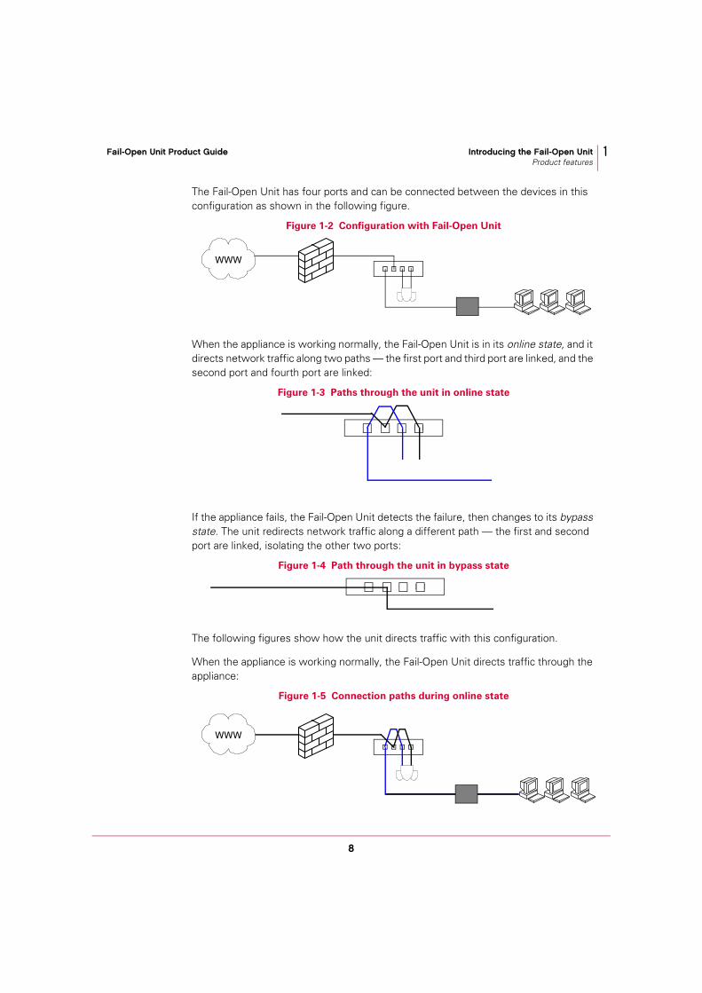
The Fail-Open Unit has four ports and can be connected between the devices in this configuration as shown in the following figure.
When the appliance is working normally, the Fail-Open Unit is in its online state, and it directs network traffic along two paths — the first port and third port are linked, and the second port and fourth port are linked:
If the appliance fails, the Fail-Open Unit detects the failure, then changes to its bypass state. The unit redirects network traffic along a different path — the first and second port are linked, isolating the other two ports:
The following figures show how the unit directs traffic with this configuration.
When the appliance is working normally, the Fail-Open Unit directs traffic through the appliance:
Figure 1-2 Configuration with Fail-Open Unit
Figure 1-3 Paths through the unit in online state
Figure 1-4 Path through the unit in bypass state
Figure 1-5 Connection paths during online state
WWW
WWW

9
Fail-Open Unit Product Guide Introducing the Fail-Open UnitProduct features
1
When the appliance fails, the Fail-Open Unit directs traffic through itself, isolating the appliance:
Detecting appliance failure The Fail-Open Unit detects a failure of the appliance by monitoring its response to a regular signal and optionally detecting link faults on the inside and outside network links.
The unit sends a regular heartbeat packet to the appliance from its third port (port C).
If the Fail-Open Unit does not receive the heartbeat packet in return on its fourth port (port D) after a specified interval (equivalent to several heartbeats), the Fail-Open Unit goes into the bypass state.
Figure 1-6 Connection path during bypass state
WWW
Figure 1-7 Monitoring the heartbeat

10
Fail-Open Unit Product Guide Introducing the Fail-Open UnitUsing this guide
1
Using this guideThis guide provides information on installing, configuring and using your product. These topics are included:
Introducing the Fail-Open Unit. An overview of the product, with a description of new or changed features; an overview of this guide; McAfee contact information.
Installing the Fail-Open Unit on page 15. How to mount the unit in the rack and connect the cables.
Testing the Fail-Open Unit on page 21. How to test the installed unit.
Frequently Asked Questions on page 27.
AudienceThis information is intended for network administrators who are responsible for installing and managing the appliance.

11
Fail-Open Unit Product Guide Introducing the Fail-Open UnitUsing this guide
1
ConventionsThis guide uses the following conventions:
Bold Condensed
All words from the interface, including options, menus, buttons, and dialog box names.
Example:
Type the User name and Password of the appropriate account.
Courier The path of a folder or program; text that represents something the user types exactly (for example, a command at the system prompt).
Examples:
The default location for the program is: C:\Program Files\McAfee\EPO\3.5.0
Run this command on the client computer:scan --help
Italic For emphasis or when introducing a new term; for names of product documentation and topics (headings) within the material.
Example: Refer to the VirusScan Enterprise Product Guide for more information.
Blue A web address (URL) and/or a live link.
Example: Visit the McAfee web site at:
http://www.mcafee.com
<TERM> Angle brackets enclose a generic term.
Example: In the console tree, right-click <SERVER>.
Note
Note: Supplemental information; for example, another method of executing the same command.
Tip
Tip: Suggestions for best practices and recommendations from McAfee for threat prevention, performance and efficiency.
Caution
Caution: Important advice to protect your computer system, enterprise, software installation, or data.
Warning
Warning: Important advice to protect a user from bodily harm when using a hardware product.

12
Fail-Open Unit Product Guide Introducing the Fail-Open UnitGetting product information
1
Getting product informationUnless otherwise noted, product documentation comes as Adobe Acrobat .PDF files, available on the product CD or from the McAfee download site.
Additional documentation for the appliance Installation Guide — System requirements and instructions for installing the appliance.
Product Guide — Introduction to the appliance and its features; detailed instructions for configuring the software; information on deployment, recurring tasks, and operating procedures.
Concepts Guide — Conceptual information about how you can use the appliance.
Help — High-level and detailed information accessed from the software application using the Quick Help button for page-level help.
Configuration Guide — For use with ePolicy Orchestrator®. Procedures for deploying and managing appliances through the ePolicy Orchestrator management software.
Release Notes — ReadMe. Product information, resolved issues, any known issues, and last-minute additions or changes to the product or its documentation.
License Agreement — The McAfee License Agreement booklet that includes all of the license types you can purchase for your product. The License Agreement presents general terms and conditions for use of the licensed product.
Contacts — Contact information for McAfee services and resources: technical support, customer service, Security Headquarters (AVERT), beta program, and training.
13
Fail-Open Unit Product Guide Introducing the Fail-Open UnitContact information
1
Contact informationThreat Center: McAfee Avert® Labs http://www.mcafee.com/us/threat_center/default.asp
Avert Labs Threat Library http://vil.nai.com
Avert Labs WebImmune & Submit a Sample (Logon credentials required) https://www.webimmune.net/default.asp
Avert Labs DAT Notification Service http://vil.nai.com/vil/signup_DAT_notification.aspx
Download Site http://www.mcafee.com/us/downloads/ Product Upgrades (Valid grant number required)
Security Updates (DATs, engine)
HotFix and Patch Releases
For Security Vulnerabilities (Available to the public)
For Products (ServicePortal account and valid grant number required)
Product Evaluation
McAfee Beta Program
Technical Support http://www.mcafee.com/us/support/ KnowledgeBase Search
http://knowledge.mcafee.com/
McAfee Technical Support ServicePortal (Logon credentials required) https://mysupport.mcafee.com/eservice_enu/start.swe
Customer ServiceWeb http://www.mcafee.com/us/support/index.html http://www.mcafee.com/us/about/contact/index.html
Phone — US, Canada, and Latin America toll-free: +1-888-VIRUS NO or +1-888-847-8766 Monday – Friday, 8 a.m. – 8 p.m., Central Time
Professional Services Enterprise: http://www.mcafee.com/us/enterprise/services/index.html
Small and Medium Business: http://www.mcafee.com/us/smb/services/index.html

14
Fail-Open Unit Product Guide Introducing the Fail-Open UnitContact information
1

15
2 Installing the Fail-Open Unit
The Fail-Open kit includes network cables and power cables, enabling it to be connected and mounted in a standard 19-inch rack. This section describes:
Checking the contents of the box.
Mounting the unit in a rack on page 16.
Preparing for cable connections on page 16.
Connecting the Fail-Open Unit on page 19.
Checking the contents of the boxBesides the unit and this guide, the box also contains:
Four CAT-5e cables with RJ45 connectors, or four fiber cables with LC connectors. One cable is a cross-over.
RS-232 cable.
Power cable(s) to suit your location.

16
Fail-Open Unit Product Guide Installing the Fail-Open UnitMounting the unit in a rack
2
Mounting the unit in a rack Before mounting the unit, observe the following points:
When deciding where to put the unit in the rack, remember to load the rack from the bottom up. If you are installing several units, start with the lowest available position first.
Do not open the unit's case. No user-serviceable parts are inside, and opening the case might invalidate your warranty.
To avoid possible electric shock, or damage to other equipment, do not connect cables until the unit is mounted in the rack.
Ensure that the power cord is suitable for the country of use. Do not modify the power cord.
Ensure that the power outlet connected to the unit meets all electrical standards for the country of use.
When connecting the appliance to the power outlet and other equipment, ensure that the cables are stowed or grouped safely, so that no one can trip over them.
Mount the unit using the integral thumbscrews. Two units can be mounted side by side.
Preparing for cable connections Before connecting cables to the appliance and the Fail-Open Unit, familiarize yourself with the main components on their front and rear sides.
Rear view of the Fail-Open Unit The following figure of the rear of the Fail-Open Unit shows the relevant parts for installing the Fail-Open Unit.
Figure 2-1 Rear view of the Fail-Open Unit
RS-232 socket DC power jacks, with retaining clip.
PR
R P

17
Fail-Open Unit Product Guide Installing the Fail-Open UnitPreparing for cable connections
2
Front view of the Fail-Open Unit The unit is available with copper ports or fiber ports. The following figures of the front of the Fail-Open Unit show the relevant parts for installing the Fail-Open Unit.
For fiber ports:
Figure 2-2 Front view of the copper-port Fail-Open Unit
Figure 2-3 Front view of the fiber-port Fail-Open Unit
Bypass indicators Ports, labelled A, B,C, D
Link and activity indicators Link speed indicators (The key on the right of the unit explains the colors that represent the speeds.)Power indicators
The left port of the pair transmits light from the unit.
The right port of the pair receives light into the unit.
BM PS L
MP
L
B
B P
L S
M

18
Fail-Open Unit Product Guide Installing the Fail-Open UnitPreparing for cable connections
2
Rear view of the applianceThis section describes the relevant parts on the appliance for installing the Fail-Open Unit. The rear panel of an appliance varies according to the type, but can have the following parts:
Power socket
If the appliance has two power modules, one acts as a redundant backup power system. The second module is in standby mode, and operates if the first module fails. The indicators on such power modules show their status:
Operational (top indicator) — Glows green when the module is in use.
Standby mode (bottom indicator) — Flashes green when the module is receiving standby power but is not in use.
No power — The indicators are off when the module is not receiving power from the power outlet.
Copper or fiber ports
For copper cables, the appliance has two RJ45 10/100/1000 Mbps autonegotiating Ethernet network ports. The ports must be used only with equipment where the connections are intended for 10 Mbps, 100 Mbps or 1000 Mbps (1 Gbps) Ethernet networks.
For fiber cables, the appliance has two fiber LC connectors for 1000 BASE-SX Ethernet network connections. Remove the dust covers before use. To protect the fibers from dust, replace the dust covers when not in use.
LAN1 and LAN2 ports connect the appliance to your network. They receive and transmit the inbound and outbound traffic, and they handle communication with the web browser that remotely manages the appliance.
The labels on the back of the appliance identify the ports, LAN1 and LAN2. For details, see the Product Guide for your type of appliance.
RS-232 serial port
System identification button
To locate the appliance within a rack, push the system identification button to flash indicators on the front and back panels. Push the button again to stop the indicators flashing.

19
Fail-Open Unit Product Guide Installing the Fail-Open UnitConnecting the Fail-Open Unit
2
Connecting the Fail-Open Unit Before connecting the Fail-Open Unit:
Configure the ports of attached network terminations (such as those devices connected to the A and B ports of the Fail-Open Unit) for autonegotiation of speed and duplex. Mismatches caused by fixed settings can disrupt network traffic.
If your appliance is in regular use, choose the least busy time to install the unit, or warn users of the temporary break in service.
To connect the Fail-Open Unit:
1 Install your appliance and configure it in Transparent Bridge Mode.
2 Connect the Fail-Open Unit to the same power source as the appliance.
3 Power up the Fail-Open Unit.
4 From a browser interface, open the Network | Settings page. Under Bypass Device Settings, select Copper/Fiber Fail Open 2000.
5 Click Apply All Changes, and type a comment when prompted.
6 Connect the RS-232 serial cable between the Fail-Open Unit and the appliance.
7 Connect LAN 1 port of the appliance to port D of the Fail-Open Unit.
8 Connect LAN 2 port of the appliance to port C of the Fail-Open Unit.
9 Connect a device (typically a router) on the outside network to port B of the Fail-Open Unit using a cross-over cable. This will act as your DTE interface.
10 Connect a device (typically a network switch) on the inside network to port A of the Fail-Open Unit using a straight-through cable. This will act as your DCE interface.
The unit should now be operating. See Testing the Fail-Open Unit on page 21 for tests to ensure that the unit is working correctly.

20
Fail-Open Unit Product Guide Installing the Fail-Open UnitConnecting the Fail-Open Unit
2

21
3 Testing the Fail-Open Unit
After you have installed the unit and connected the copper or fiber cables, you can test that the unit is operating correctly. This section describes:
Understanding the indicators on the unit on page 22. Read this first to become familiar with the unit.
Testing the Fail-Open Unit on page 23.
Further testing on page 24.
Configuring the unit on page 24.
For troubleshooting, see Frequently Asked Questions on page 27.

22
Fail-Open Unit Product Guide Testing the Fail-Open UnitUnderstanding the indicators on the unit
3
Understanding the indicators on the unit The indicators on the front panel show the state of the unit.
Figure 3-1 Indicators on the front panel of the Fail-Open Unit
Key Label Description
The unit has two power supplies. The green indicators (labeled 1 and 2) show which power supply is providing power.
BYPASS Two green indicators show whether the unit is bypassing traffic:
The OFF indicator glows while the appliance is working correctly.
The ON indicator glows if the appliance fails, and the unit is bypassing the traffic.
LINK The copper unit has a link speed indicator in the top left of each port. Each indicator glows with a color corresponding to the link speed. See the key on the right of the unit. The fiber unit has a group of four indicators — one per port.
Each indicator glows steadily when a good link is established.
ACT The copper unit has an activity indicator in the top left of each port. The fiber unit has a group of four indicators — one per port.
The indicator flashes when there is activity on a good link.
Copper Fiber
B
B
L
S L MM
M
B
S
L

23
Fail-Open Unit Product Guide Testing the Fail-Open UnitTesting the Fail-Open Unit
3
Testing the Fail-Open Unit This test ensures that a Fail-Open Unit is correctly connected and working. If the test fails, check the connections, and see Frequently Asked Questions on page 27.
To test the unit:
1 At the front panel, check that the unit is on — the power and the BYPASS OFF indicators glow.
2 At the appliance interface, open the Network | Settings page, and under Copper/Fiber Fail-Open 2000:
Set Watchdog Polling Rate to 1 second, and Watchdog Time to 10 seconds.
Set the line speed.
If applicable, select Enable Gigabit, Autonegotiate, and Full Duplex.
3 Click Apply All Changes, and type a comment when prompted.
4 Remove the cable from the C port.
a After approximately 10 seconds (the Watchdog Time), notice that the BYPASS ON indicator glows.
b Re-insert the cable.
c After approximately one second (the Watchdog Polling Rate), notice that the BYPASS OFF indicator glows.
5 Repeat Step 4 for the D port.
6 When the test is finished, set the values at the Network | Settings page to suit your network. See Configuring the unit on page 24.
For further testing, see page 24.
24
Fail-Open Unit Product Guide Testing the Fail-Open UnitFurther testing
3
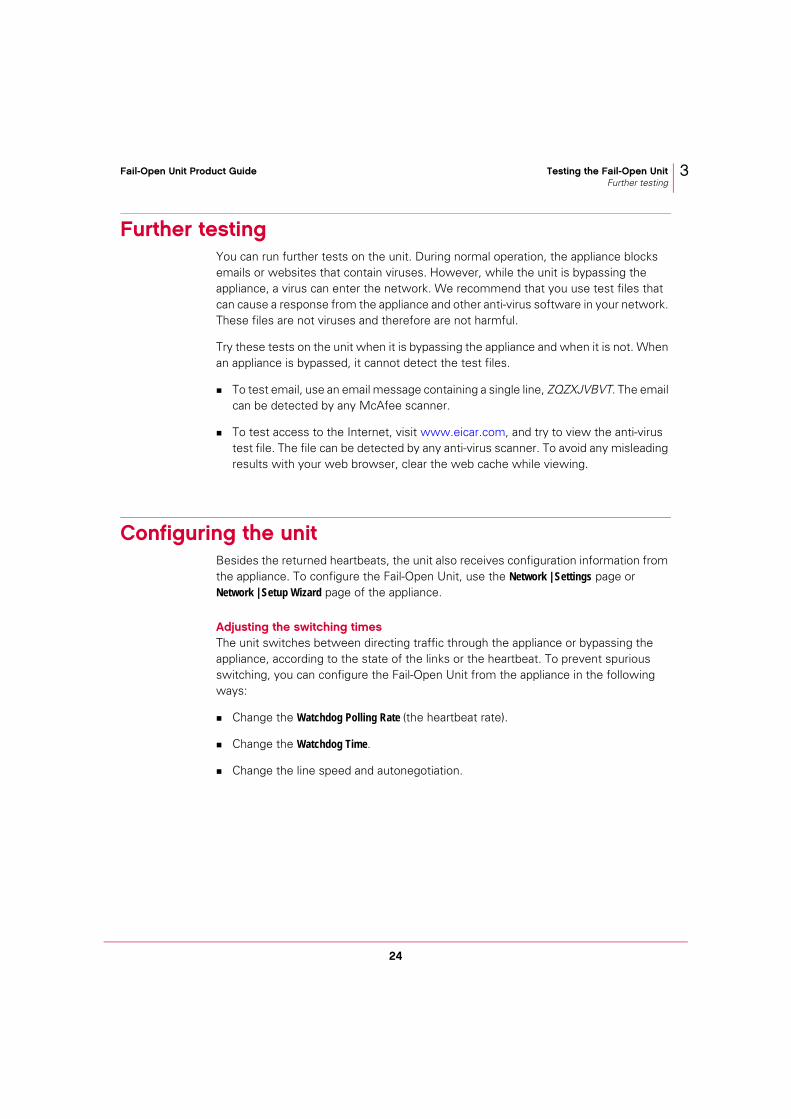
Further testing You can run further tests on the unit. During normal operation, the appliance blocks emails or websites that contain viruses. However, while the unit is bypassing the appliance, a virus can enter the network. We recommend that you use test files that can cause a response from the appliance and other anti-virus software in your network. These files are not viruses and therefore are not harmful.
Try these tests on the unit when it is bypassing the appliance and when it is not. When an appliance is bypassed, it cannot detect the test files.
To test email, use an email message containing a single line, ZQZXJVBVT. The email can be detected by any McAfee scanner.
To test access to the Internet, visit www.eicar.com, and try to view the anti-virus test file. The file can be detected by any anti-virus scanner. To avoid any misleading results with your web browser, clear the web cache while viewing.
Configuring the unitBesides the returned heartbeats, the unit also receives configuration information from the appliance. To configure the Fail-Open Unit, use the Network | Settings page or Network | Setup Wizard page of the appliance.
Adjusting the switching times The unit switches between directing traffic through the appliance or bypassing the appliance, according to the state of the links or the heartbeat. To prevent spurious switching, you can configure the Fail-Open Unit from the appliance in the following ways:
Change the Watchdog Polling Rate (the heartbeat rate).
Change the Watchdog Time.
Change the line speed and autonegotiation.

25
Fail-Open Unit Product Guide Testing the Fail-Open UnitConfiguring the unit
3
Changing settings The default settings are usually suitable but you can change them at any time from the appliance interface on the Network | Settings page under Bypass Device Settings.
Table 3-1 Settings at the appliance interface
Label Range or Setting
Default value
Description
Select bypass switch
Off/1000/2000
Off Select 2000 for this Fail-Open Unit. This enables the appliance to operate with the Fail-Open Unit. (If you have an earlier design, select 1000.)
If you select Off, any values that you have set in the other fields are retained so that you can use them again later.
Watchdog Polling Rate
1-254 seconds
1 second This determines how often the Fail-Open Unit sends a heartbeat packet to the appliance.
Watchdog Time
1 - 254 seconds
10 seconds
If this time has elapsed since the Fail-Open Unit last received a heartbeat, the unit switches into bypass state.
The Fail-Open Unit switches out of bypass state upon receiving a heartbeat again.
We recommend that this value is at least three times the Watchdog Polling Rate. If the appliance is handling heavy traffic, it might be unable to return the heartbeat, causing the Fail-Open Unit to bypass all traffic (unscanned) during busy times.
Line speeds 10 Mbps, 100 Mb, 1 Gbps
All This determines the available line speeds. Select any of Enable 10 Mbps, Enable 100 Mbps, and Enable Gigabit.
Full Duplex On or Off On Full Duplex must be on for the 1 Gbps line speed.
Link Fault Detect
On or Off On When this is On, the Fail-Open Unit drops the remaining full-duplex link when one side fails, alerting connected devices of a failure on both sides of the link.
Autonegotiate On or Off On If the devices that normally communicate with the appliance use autonegotiation, set this checkbox.
Autonegotiate must be on for the 1 Gbps line speed.

26
Fail-Open Unit Product Guide Testing the Fail-Open UnitConfiguring the unit
3

27
4 Frequently Asked Questions
This section answers questions that can arise when using the Fail-Open Unit:
How can I protect my network if the appliance fails? on page 28
How can I check the copper cables? on page 28
Why can’t I change any settings on the Fail-Open Unit? on page 29
What do I need to do when upgrading the appliance? on page 29
After the Fail-Open Unit changes state, why does my network take some time to recover? on page 29
Can I communicate with an appliance when the Fail-Open Unit is in bypass state? on page 29
How do I ensure the correct line speeds and duplex mode? on page 30
How can I view the activity of the Fail-Open Unit? on page 31
What are the basic specifications of the Fail-Open Unit? on page 31

28
Fail-Open Unit Product Guide Frequently Asked Questions 4
How can I protect my network if the appliance fails? If the appliance fails, all traffic passes through the Fail-Open Unit instead. Users can send and receive email or access web sites, as before. However, no scanning takes place. Spam and phish email can enter your network, viruses are not stopped, and users can view inappropriate web sites.
Until the appliance is reinstated, your network is vulnerable to viruses and other potentially unwanted software. Fortunately, your network is likely to have some other (system) protection, which protects individual computers. For example, on-access scanners on desktop computers can detect any viruses when a file is opened. Depending on your traffic and the other protection within your network, you can try the following methods to protect your network until the appliance is available again:
Inform users of the disruption to their service.
Warn users that the protection will be less secure during this time. Advise them against accessing files by portable media such as diskettes, CDs, DVDs, and USB memory devices, to prevent any propagation to other networks.
Advise users against opening or forwarding email from unknown senders.
Run extra on-demand scanning on servers.
Strengthen the policies that ePolicy Orchestrator applies to individual computers and servers in your network.
How can I check the copper cables?Correct cables are important for proper operation of the unit, particularly when using copper cable. Problems with cables can result in confusing displays on the link indicators and prevent the unit bypassing the appliance. In general, the copper units are for use with one straight-through cable and one cross-over cable between a network switch and a router (or other NIC-type interface). Ports C and D of the Fail-Open Unit (which connect to the appliance) are intended for NIC-type interfaces, using straight-through cables.
If you use other network configurations, you must maintain the cable polarity. To check the cables:
Confirm that devices connected to ports A and B can communicate when the Fail-Open Unit is in bypass state.
In bypass state, the Fail-Open Unit connects each pin of port A to port B.
Figure 4-1 Connections during bypass state

29
Fail-Open Unit Product Guide Frequently Asked Questions 4
To put the Fail-Open Unit into bypass state immediately, remove its power cord. Confirm that devices connected to ports A and B are communicating. If not, directly connect the two external cables with a female-female RJ45 coupler.
Confirm that the link signals are active.
Connect the RJ45 cables to the Fail-Open Unit one at a time, and check that the link indicators glow.
Why can’t I change any settings on the Fail-Open Unit? You can manage the unit only if the appliance is configured to communicate with it.
In the appliance interface, open the Network | Settings page, and under Bypass Device Settings, select Copper/Fiber Fail Open 2000.
If the appliance is being bypassed by the Fail-Open Unit, you cannot use the browser interface, and must use the console interface instead.
What do I need to do when upgrading the appliance? By default, an appliance does not enable the Fail-Open Unit. If you upgrade the appliance, the Fail-Open Unit will go into bypass state, effectively isolating the appliance, and preventing access via the browser interface.
When upgrading, you normally provide some basic configuration at the console interface. At the Bypass option, enable the Fail-Open Unit (version 2000). You can then configure other features from the browser interface.
After the Fail-Open Unit changes state, why does my network take some time to recover? If Spanning Tree Protocol (STP) is enabled in your network switch or Ethernet switch, clients might experience a 30-second delay before their connections are restored. You can fix this by setting each client port into PortFast mode.
Can I communicate with an appliance when the Fail-Open Unit is in bypass state? If the appliance has not suffered a serious failure, you can normally communicate with it via the web browser. However, if the Fail-Open Unit has switched to bypass state, the appliance is isolated from the network, and you cannot communicate with it.
This configuration has some advantage over a configuration that has only a single appliance with no Fail-Open Unit. Network traffic continues to flow so users still have their service while you examine why the appliance failed.

30
Fail-Open Unit Product Guide Frequently Asked Questions 4
However, network traffic is not scanned. See How can I protect my network if the appliance fails? on page 28. The appliance is isolated from the network and cannot be managed. For example, the appliance cannot fetch updates, and you cannot examine its logs.
If the appliance is bypassed while operating as an ICAP server, any ICAP client cannot communicate with the ICAP server, so you must configure the ICAP client to handle this situation.
If your appliance includes a Remote Access Card, you can communicate with the appliance remotely using the card even when the appliance is bypassed.
How do I ensure the correct line speeds and duplex mode? When you are setting up your network, ensure that all networking devices that interact with the Fail-Open Unit operate in the same speed and duplex mode.
To change the speed and duplex mode of the appliance to be consistent with the DTE and DCE devices that it interfaces, change the network settings in the appliance, using one of the following:
At the console, run the command, webshield config.
At the browser interface, select Network | Settings | Bridge | Advanced LAN1 and Network | Settings | Bridge | Advanced LAN2.
If you try to connect devices operating at different speeds to the Fail-Open Unit, the Fail-Open Unit cannot negotiate each interface separately nor run each port in different speeds and duplex modes.
In the above situation, the Fail-Open Unit will determine the lowest speed and duplex mode of all the ports, and apply the same speed and duplex mode to all the ports so that no packets are lost during its normal operation.
The Fail-Open Unit will then start to negotiate the speed with the link partner. The Fail-Open Unit will bring down the links briefly but still long enough for the link partner to detect the changes in configuration.
In this way, all the devices connected to the Fail-Open Unit will run at the same speed and duplex mode.

31
Fail-Open Unit Product Guide Frequently Asked Questions 4
How can I view the activity of the Fail-Open Unit?To view the activity:
1 In the browser interface, open the Monitor | Logs page.
2 Select Hardware and Resources.
3 Click Next.
4 Look for bypass in the Application column.
5 Select an entry, and click Event Details to view the details of the event.
What are the basic specifications of the Fail-Open Unit?
Parameter Value
Size 29 x 254 x 165 mm (1.125 x 10 x 6.5 inches) — copper
29 x 292 x 165 mm (1.125 x 11.5 x 6.5 inches) — fiber
Operating temperature
0oC to 55oC — copper
5oC to 40oC — fiber
Storage temperature -10oC to 70oC
Relative humidity 10 - 95% maximum, non-condensing
Electrical ratings 100-240 V, 47-63 Hz, 0.5 A
Copper ports IEEE 802.3
Fiber ports IEEE 802.3u 1000 BaseSX (multimode) compatible with LC connectors

32
Fail-Open Unit Product Guide Frequently Asked Questions 4


Copyright © 2006 McAfee, Inc. All Rights Reserved.
mcafee.com
700-1302A00