failed substation equipment failure modes & mechanisms modes and... · 23.05.2018 · failed...
TRANSCRIPT

Failed Substation EquipmentFailure Modes & Mechanisms
Rick Hackman, NERCMay 23, 2018
RELIABILITY | ACCOUNTABILITY2
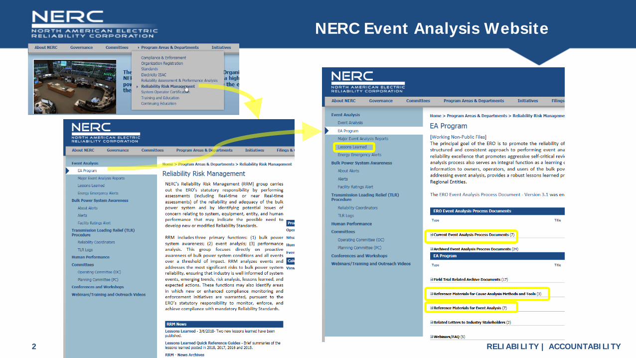
NERC Event Analysis Website

RELIABILITY | ACCOUNTABILITY3
NERC Event Analysis Website

RELIABILITY | ACCOUNTABILITY4
NERCTV
Placeholder slide for FMM Intro Video

RELIABILITY | ACCOUNTABILITY5
Failure Modes and Mechanisms (FMMs)
Improve Equipment Reliability by Learning from Failures
• Failure Modes are what gets your attention
• Failure Mechanisms are how the equipment gets going on the path to a failure• Equipment Failures have logical cause-and-effect relationships behind
them. • Physical Evidence Examination and Root Cause Analysis can reveal what
Failure Mechanisms were involved.• Aging is not a ‘cause.’ It is just a catch-all term for slow moving Failure
Mechanisms. • Failure Mechanisms are detectable. Many can be stopped, or at least slowed
down so they can be corrected before causing a failure.

RELIABILITY | ACCOUNTABILITY6
Combine Failure Modes & Mechanisms w/Other EA Tools
• Improve “Addendum for Events with Failed Station Equipment”usefulness
• Capture Equipment FM&M data to discover trends and patterns just like Event Cause Codes
• Discover which FM&Ms impact Reliability most to help prioritize prevention efforts
• Develop Failure Mechanism detection methods to spot issues prior to failure
• Cross Reference FM&M with Lessons Learned (and vice versa)
• Provide a equipment failure analysis resource for engineers and field workers

RELIABILITY | ACCOUNTABILITY7
Cause Code Tree Structure
Many people involved in the Event Analysis Program are already familiar with the Cause Codes used in Event Analysis
FMM allows more equipment -specific coding.
https://www.nerc.com/pa/rrm/ea/EA%20Program%20Document%20Library/CCAP_Manual_January_2018_Final_Posted.pdf

RELIABILITY | ACCOUNTABILITY8
Addendum for Events with Failed Station Equipment
The Addendum for Events with Failed Station Equipment is being revised to capture FMM data.

RELIABILITY | ACCOUNTABILITY9
New Draft Addendum for Events with Failed Station Equipment
Dropdown selections for Equipment Types and Failure Mechanisms

RELIABILITY | ACCOUNTABILITY10
Generic Failure Modes & Mechanisms Layout
Failed Equipment Type
Failure Mode 1 Failure Mode 2 Failure Mode 3
Failure Mechanism 1
Failure Mechanism 1
Failure Mechanism 1
Failure Mechanism 2
Failure Mechanism 2
Failure Mechanism 2
Failure Mechanism 3
How this developsHow this develops
More detail, notes, cures, salves...
More detail, notes, cures, salves...
And then...
And then...
How this developsHow this develops
OrOr
ThisThis ThatThat
++
A required condition
A required condition
Another required condition
Another required condition
1
1
LL20180101

RELIABILITY | ACCOUNTABILITY11
Bushing Failure Modes & Mechanisms
Developing issue often
visible prior to failure
Developing issue often
visible prior to failure
Drought conditions can make this more likely
(accumulation not washed off by rain)
Developing issue often
visible prior to failure
DRAFT Bushing Failure
Approaching loss of margin to failure may
be detectable by testing or Infrared
Oil leak may be externally
visible
AND
Connection to a higher voltage source, phase to phase fault, lightning…
An External Fault on a nearby phase can
create high voltage stress on another
Beyond Design Voltage Stress
External Fault
Contamination
OR
Contains conductive uric
acid and salts
Salt
Bird Excrement
Local Pollutants
UV
HeatErosion
(usually wind driven grit / sand)
Issues for Polymer Bushings
Assis
ts B
uild
-up
Cleaning Maintenance does not keep up with
contamination (maintenance not done, not
timely, or contaminant builds up abnormally fast)
OR
Issue for Porcelain or
Polymer Bushings
Glaze / Coating deterioration
(easier to stick to)
Snow / Ice Coating
Animal
Blown objects
Bridging by object
Thrown objects
Vegetation Growth
Grading Resistor or
Choke Failure
Mechanical Failure
Impact Mechanical Overload
Cyclic Mechanical Loading
Blown objects
Gunshot
Vehicle
Attached Weight
Line Tension
Misaligned assembly
Strong Local Vibration
Source
Wind (line movement)
Seismic Events
Seismic Events
Work in Area
Bus / Device / Support / Other
Structure Foundation Movement / Failure
Erosion
Concrete Issues
Flooding
LTA site preparation
Seismic Events
LTA footing
LTA assembly
Generic Bushing Failure Modes and Mechanisms
This includes not just the end seals, but housing defects,
bushing failures, tank (can) weld failure,
internal pressure, or other boundary
failures.
May be caused by impact, assembly
error, corrosion, LTA material choice, temperature (or
pressure) extremes or cycling
Corrosion of metal if both are present
Machining / Cutting Oil has sometimes been found in bushings – it slowly breaks down under voltage stress
providing carbon for tracking
Seal failure
Other Foreign Material
Salts
OR
OR
ORAND
Locally Available Contaminants /
Foreign Materials
Not Necessarily Locally Available Contaminants /
Foreign Materials
Moisture intrusion
Foreign Materials left
inside by Manufacturer
Material Defects from Manufacturer
While polymer or oil impregnated paper dielectric does not ‘leak out,’ it can wick up moisture from a seal failure, increase voltage stress, and become
contaminated by other foreign matter as well. See also transformer FMM for paper breakdown products.
Leakage of Dielectric
(SF6 or Oil)
Voltage stress induces Breakdown of Carbon bearing
materials
Voltage stress lines up small amounts of conductive material deposits for tracking. Otherwise they would remain at point of
entry or fall by gravity…
Contamination of Solid Dielectric
(Paper or Plastic)
Increases Voltage Stress Locally
Conductive Material where it should not
be
Voltage Stress (Plenty is available when the device is in service)
Voids
GaseousByproducts
Tracking
Internal Fault
AND

RELIABILITY | ACCOUNTABILITY12
SF6 Breaker Failure Modes & Mechanisms

RELIABILITY | ACCOUNTABILITY13
Oil Filled Transformer Failure Modes & MechanismsOil Filled Transformer Failure
Fura
ns in
oil
as 2
-fura
ldeh
yde,
par
ts p
er m
illio
n
Corr
espo
ndin
g De
poly
mer
izatio
n (D
P) V
alue
Rough relationship of Furans in oil and paper insulation Cellulose Depolymerization (DP) for an ordinary power transformer having an Oil to Paper Ratio of 20:1 by weight with good circulation and oil that has not been replaced / purified for over two years
0
>10
1200
<200
250
450
700
10
1.0
0.1
Healthy
New
Moderate
Deteriorated(sample furans annually)
End of Life
Failure Imminent
Transformer ConditionDP2FAL ppm
2-FAL rate of rise of 25 ppb/month is cause for concern.
DRAFT
Bouncing & vibration mechanically stresses paper insulation. If it is sufficiently embrittled, pieces may detach from the conductor. Failure occurs upon reenergization (may be detected
with meggar prior to energizing).
Eventually, enough embrittlement will develop to fail the insulation with tiny stresses – gravity or
even the 120Hz vibration ‘hum’ induced in magnetic materials in a 60Hz AC system can be enough.
Winding Failure
Turn to Turn short
Winding to Tank FaultWinding Open
Tracking
Chemical, Heat, or Voltage Stress induced breakdown of
Carbon bearing materials
Paper Insulation Embrittlement
Mechanical Damage – Displacement of
internals
Paper Insulation failure
Other Breakdown products
Carbon Monoxide
Transformer Loading largely determines the amount of overall
heating, so loading directly impacts paper insulation lifespan.
Tracking can create localized
arcing and heating
Loss of seal / moisture intrusion, exhaustion of desiccant, presence of
oxygen / hydrogen with arcing
Moisture
Heat
Acids (corrosive, may degrade other materials)
Peroxides
Carbon Dioxide
Arcing
Fault(may be located a long
distance away)
Sudden Load Change
Sudden Load Loss di/dt ∝ dV
Hit / Bounced / Dropped during
shipping
Lightning
Reduce the chance of overvoltage damage
with Lightning Arrestors
Overvoltage
Current chopping by a breaker
opening(di/dt ∝ dV)
Carbon (will track)
Release of furans (measurable for determining paper insulation condition)
Chemical degradation, Depolymerization of
cellulose (loss of tensile strength, fragmentation)
Pape
r Bre
akdo
wn
Bypr
oduc
ts
Transporting Used Transformer
Anything that causes winding to move/squirm/shift mechanically stresses paper insulation. If it is sufficiently embrittled, pieces may detach from the conductor
and cause sudden failure.
Winding MovementCan
Hasten Failure
Voltage stress lines up small amounts of conductive material deposits for tracking. Otherwise they would remain near where
they formed, move with oil flow, or fall by gravity…
Voltage Stress (Usually available when the
device is in service)
AND
Loose / Foreign Materials left inside
by Maintenance
Loose / Foreign Materials left inside
by Manufacturer
Left Loose / Damaged by Maintenance
Left Loose / Damaged by
Manufacturer
Hit / Bounced / Dropped during
Installation
Loose Material moved by oil flow
Loose Material moved by violent
event
Loose Conductive Material
1
1
Volta
ge c
reat
ed fr
om
deca
ying
mag
netic
fiel
d in
an
indu
ctor
Bad Connection or Splice
Damaged by Maintenance
Melted by high loading
(normally at high resistance connection or small cross-section/
nicked spot)
2
34
Tap Changer Failure
Contact Erosion
Arcing Localized Heating
High Resistance Deposits
Tracking
Mechanical Binding
Low Resistance Deposits (Shorting)
Contaminants, Foreign
Materials
Motor Failure
Loss of Power
Mechanical Failure (Impeller broken, bearing failure,
drive connection, mounting broken, etc.)
Jammed / Fouled
Foreign Material, Broken / Loose
Parts
Sometimes...
MoreDegradation
products
Most things that can damage other internals can damage
internal leads
Internal Leads Fault
Deterioration of Insulation
Moisture
Heat
Arcing
Free Oxygen
AcidsFrom Contaminants or Paper & Oil Breakdown Byproducts
Bad Connection or Splice
Damaged by Maintenance
Melted by high loading
(normally at high resistance connection or small cross-
section/ nicked spot)
2
3
1
4
Dielectric Failures
Leakage(so now its air, large
bubbles)
Contamination from External Sources (foreign material)
Conductive Contamination or
Displacement (bubbles) from Internal Sources
Sulfur Compounds
Moisture
Heat
Arcing
Oxygen Oil Breakdown
Carbon
Ethylene
Acetylene
Hydrogen
Acids
Left by Maintenance
LTA Breather condition
Seal Failures
Left by Manufacturer
Contaminated Oil Source
Furans, Lignans
Chlorine Compunds
Fluorine Compounds
Water
Paper / Rubber /
Resin /Wood / Plastic / Coatings
breakdown2
3
1
4
This is usually a seasonal issue. Stepped up visual checking and scheduled maintenance during
those periods can help keep cooling surfaces clean
Cooling Failures Tank FailureTank Failure mechanisms can also cause smaller scale leaks- Think of
Tank Failure as Super Gross Leakage
Coolant Leak
External Fouling of Radiator/ Cooling Fins
Internal Blockage (oil can’t circulate)
Pump Failure
Fan Failure
Rupture
Damaged by External Forces
Corrosion
Leaves, Cottonwood, wind
blown debris
Vegetation GrowthInsects, Insect nests
Blown objects
Gunshot
Vehicle
Environmental condition (Acids,
Salts,…)
Often corrosion is faster in the Heat Affected Zone of
welds. Coating/Paint quality and condition
is very important there.
Paint/Coating issue
Lack of condition check
Internal pressure buildup w/o relief
Explosive gas plus O2
Major Fault Energy Release
Bird / Animal Nesting Materials
Work in Area
Other Fouling Materials
Motor Failure
Loss of Power
Mechanical Failure (Blades broken, bearing failure,
drive connection, mounting broken, etc.)
Jammed / Fouled
Valves Closed
Ice Plug (Water goes to low spot,
freezes in winter)
Foreign Material
Accumulation of solid/semi-solid deterioration byproducts (from oil,
insulation, and other internals)
Motor Failure
Loss of Power
Mechanical Failure (Impeller broken, bearing failure,
drive connection, mounting broken, etc.)
Jammed / Fouled
Seal Failure
Drain Plug / Valve Open/ Loose
Weld Failure
External Instrument / Line
leak
Mounting / Bolt Hole to Interior Leak (assembly / design / modification /
maintenance issue)
4
Ordinary feedback loop, includes core lamination insulation – Vibration slowly gets
worse over time. If sound gets really loud quickly, there’s something else going on &
possible catastrophic failure - run away!
120Hz Vibration
High current on primary, loss of efficiency, extra noise, harmonics generated on secondary, wasted
energy turns into lots of heat, flux shaping issues – may drive circulating current in other
transformer structures. CT reading on secondary may be misleading.
Harmonics
Large DC input (or small margin to
saturation in design)
Overvoltage
Magnetic Saturation
Detectable decay products in Oil - Phenols & Cresols -
concern if >1ppm
Deterioration of Resin, Wood, Plastics (Insulation,
Spacers, Structural Laminates, incl in core)
Moisture
Free Oxygen
Arcing
Steals from design life of transformer, accelerates insulation
‘aging’ by additional heating
If kept within the normal rating with proper maintenance and no major external events, the transformer
should last for and probably exceed its design life.
Excess Heating from Core
Core Delamination
Eddy Current Heating
Operational Heating
Overloading(higher than normal, but below emergency limit)
Long Term Load(within normal rating)
2 3
Deteriorated/ loosened interior mountings, plywood
or plastic structures
Sometimes due to a mistake in parallel transformer
selection, installation & use Improper Load ‘Hogging’ (lower impedance path)
This is often due to load growth on one phase while only monitoring current on some other phase. ie, being cheap instead of monitoring
all 3 phases
Not enough to trip, but still a load….
Design and Operating Philosophy. There is a potential trade of Transformer life for deferred spending,
planning, ability to use a less expensive transformer (instead of one sized for moregrowth)
Sometimes made worse by transformer ordering lead
time, budget and scheduling constraints
Imbalanced Phase Loads with inadequate Instrumentation
Relay Settings or Fusing allows some loading above normal rating
AND
OR
Organizational Tolerance of moderate faults
Load Growth not planned for or kept up with
Heat
2 31 4
While oil impregnated paper dielectric does not ‘leak out,’ it can
wick up moisture from a seal failure, and become contaminated
by other foreign matter as well. See also transformer FMM for paper
breakdown products.
Drought conditions can make this more likely
(accumulation not washed off)
Contains plenty of uric acid and salts, which
are conductive
This includes not just the end seals, but housing
defects, cracked porcelain, grout failure, pressure or oil
gauge problems, or other boundary failures.
Bushing Failure
Mechanical Failure
Impact Mechanical Overload
Cyclic Mechanical Loading
Blown objects
Gunshot
VehicleAttached Weight
Line Tension
Misaligned assembly
Strong Local Vibration
Source
Wind (line movement)
Seismic Events
Seismic Events
Work in Area
An External Fault on a nearby phase can
create high voltage stress on another
External Fault
Salt
Bird Excrement
Local Pollutants
Glaze / Coating deterioration
(easier to stick to)
Animal
Blown objects
Bridging by object
Thrown objects
UV
HeatErosion
(usually wind driven grit / sand)
Contamination
Thes
e 2
are
mor
e of
a p
robl
em fo
r po
lym
er b
ushi
ngs
Snow / Ice Coating
Assis
ts
Vegetation Growth
OR
Internal Fault / Tracking
May be caused by impact, assembly error, chemical
attack, LTA material choice, temperature (or pressure)
extremes or cycling
Seal failure
Other Foreign Material
Salts
Voltage stress lines up small amounts of conductive material deposits for tracking. Otherwise they would remain at point of
entry or fall by gravity…
AND
OR
Can include loose parts, dropped screws, nuts, bolts, wire, scrap, dirt,
fluids, greases, etc.
Foreign Materials left inside by Maintenance
Foreign Materials left inside by on-
site assembly
OR
ORAND
Locally Available Contaminants /
Foreign Materials
Not Necessarily Locally Available Contaminants /
Foreign Materials
Moisture intrusion
Induces Breakdown of Carbon bearing
materials
Cond
uctiv
e M
ater
ial n
ot
whe
re it
shou
ld b
e
Machining / Cutting Oil has sometimes been found in
bushings – it slowly breaks down under voltage stress providing
carbon for tracking
Foreign Materials left inside by Manufacturer
Corrosion of metal internals
if both are present
Beyond Design Voltage Stress
Connection to a higher voltage source, phase to phase fault, lightning…
Leakage of Dielectric
(SF6 or Oil)
Voltage Stress (Usually available when the device is in service)
Sometimes oil sight gauges get dirty and the real level may not be apparent (Stain
makes it look full when it may not be).

RELIABILITY | ACCOUNTABILITY14
Failure Modes & Mechanisms

RELIABILITY | ACCOUNTABILITY15
Failure Modes & Mechanisms

RELIABILITY | ACCOUNTABILITY16
Failure Modes & Mechanisms

RELIABILITY | ACCOUNTABILITY17
Surge Arrester Failure Modes & Mechanisms
DRAFTDRAFT
DRAFT
Drought conditions can make this more likely (doesn’t get washed off)
Surge ArresterFailure Modes & Mechanisms
DRAFTMetal Oxide (ZnO)Thermal RunawayExpect rapid failure if >>1500A/cm2
Metal Oxide (ZnO)Block Failure
Silicon Carbide (SiC)Thermal Runaway
Silicon Carbide (SiC)Block Failure
SuccessiveBlock Failures by Shorting
Accelerates failure of
additional blocks
High Internal Pressure and Temperature /
Rapid Energy Release
Continuous or Frequent Operation
Or High Leakage Current is Detectable
with IR Camera
Curr
ent D
ensit
y >4
00A/
cm2
Curr
ent D
ensit
y <4
00A/
cm2
If energy is absorbed faster than the
Arrester Housing can dissipate it as heat
Detectable on Ground Wirewith Clamp-On
Or installedAmmeter
Metal Oxide temperature rises
above thermal stability limit
AND
Voltage > Max Continuous Operating Voltage (MCOV)
Higher than normal Voltage
If la
rge
amou
nt
of e
nerg
y
If low amount of energy failure is
unlikely
Anything that heats up the
block prior to the surge assists this
Air space acts as insulation.
Fiberglass wrap and is better
1
1
Lightning, Various
Transients
2
If energy is absorbed faster than the
Arrester Housing can dissipate it as heat
SiC temperature rises above thermal stability
limit
AND
Anything that heats up the block prior to the surge assists this
Air space acts as insulation. Fiberglass wrap is better. Some use sand or aluminum oxide mixed in a polymer
SiC has more current flow than ZnO for a given voltage, so it heats up more
Moisture and contaminants from seal failure assists this
Ozone, arcing and corona assists this
High internal pressureKaboom!
Mechanical Failure
Mechanical Overload
Impact
Cyclic Mechanical
Loading
Blown objects
Gunshot
Vehicle
Attached Weight
Line Tension
Strong Local Vibration
Source
Wind (line movement)
Seismic Events
Seismic Events
2
High internal pressureKaboom!
Porcelain Housing – Rapid Stress Crack
Propagation
Polymer Housing – Tends to blow out /
shred
If violent internal pressure driven, this is a Personnel Safety Hazard. Shrapnel may damage other nearby equipment
Not as much a Personnel Safety Hazard as Porcelain . Very unlikely to
damage other nearby equipment
Some arrestors are equipped with Rupture Diaphragms and relief vents that attempt to
avoid the explosive shattering porcelain hazard
External Fault
Salt
Bird Excrement
Local Pollutants
Glaze / Coating deterioration
(easier to stick to)
Animal
Blown objects
Bridging by object
Thrown objects
UV
Heat
Erosion(usually wind driven grit / sand)
Contamination
Mor
e of
a p
robl
em fo
r po
lym
er
Snow / Ice Coating
Contains plenty of uric acid and salts, which are conductive
Assis
ts
Vegetation Growth
Internal Fault / Tracking
Breakdown of Carbon bearing
materials
Seal failure
Moisture intrusion
Foreign Material
Salts
Corrosion of springs and other
metal internals
Voltage Stress(otherwise conductive material
deposits are random, not lined up for tracking)
AND
OR
Spark GapGrading Resistor
SiC Block
Rupture Diaphragm
Rupture Diaphragm
End Seal
End Seal
End Seal
End Seal
Relief Vent /Blast Guide
Relief Vent /Blast Guide
Metal Oxide (ZnO) Block
Hold-DownSpring
Housing and Sheds (Porcelain or Polymer)
Lower Voltage Required to trigger:Frequent or Continuous operation
More current
leakage and heating with more block
damage
Heating From Surge
Operation
SiC generally has a shorter service life than ZnO
O-Ring Degradation
Operation and Temperature Cycling
Expansion Bellows / Rupture Disc Fatigue
Impact Damage
Off Center /Attachment stresses
Fatigue failure more likely if seal / rupture disc has sharp step changes instead of rounded profile – think ziggurat vs baby food jar lid
UV (if exposed)Too Cold for Material (shrinks, opens)
Ozone
Elastomer softens, expands or dissolves
Exposure to an incompatible organic fluid or vapor (can be airborne pollutants, oils, solvents, fuels)
Inorganic Chemical Attack (Acids, Bases)
Elastomer shrinks, hardens, cracks, may
‘take a permanent set’
Some agricultural chemicals, fossil fuel burning exhaust, NOx, SOx, etc.
Assembly error, Installation off-center or high mechanical tension issues, Attachment mechanical bending stress issues, Very Strong Winds
44
Note: The majority of Surge Arrester Failures pass through Seal
Failure and Moisture Intrusion
Note: The majority of Surge Arrester Failures pass through Seal
Failure and Moisture Intrusion4
Send Failure Modes and Mechanisms Improvement Comments, Corrections, Additions, Lessons Learned, Diagnostics / Symptom Monitoring Ideas, & Failed Equipment Photos to:
Richard HackmanSr. Reliability Advisor, Reliability Risk ManagementNorth American Electric Reliability Corporation3353 Peachtree Road NE, Suite 600 – North TowerAtlanta, GA 30326404-446-9764 office | 404-576-5960 cellEmail [email protected]
Some of this Group is
Detectable byexternal
examination
Open / High Resistance Loss of Function /
Threshold Too High
Stolen Ground
Corroded Lead or connection
Other lead / connection
failures
3
Loose Connection (either end) DRAFT
Gap Operating Voltage Change
Gap Grading Resistor Shorted
Moisture and contaminants from
seal failure
Ozone (from arcing or corona in air) chemical
attack
Corrosion leads to dimensional
changes
Deposits of melted gap plate material Previous operations
3
Lower Voltage Required(gap smaller, conductive deposits
closer to bridging)
Higher Voltage Required(gap larger, resistive coatings/deposits)
Vaporization / Redistribution of
gap plate material
4

RELIABILITY | ACCOUNTABILITY18
Capacitor Bank Failure Modes & Mechanisms
RELIABILITY | ACCOUNTABILITY19
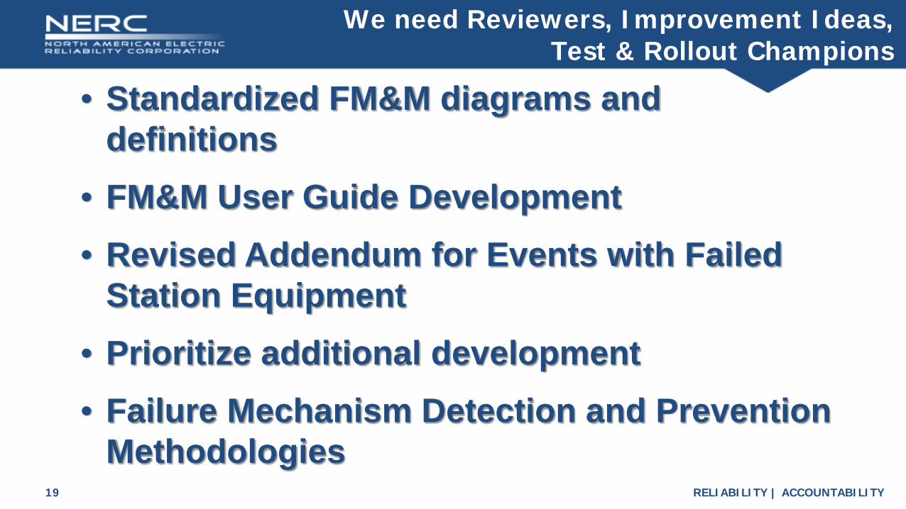
We need Reviewers, Improvement Ideas, Test & Rollout Champions
• Standardized FM&M diagrams and definitions
• FM&M User Guide Development• Revised Addendum for Events with Failed
Station Equipment• Prioritize additional development• Failure Mechanism Detection and Prevention
Methodologies

RELIABILITY | ACCOUNTABILITY20
FM&M Volunteers
• 1 from MRO• 1 from BPA• 1 from WAPAWe need more!
Volunteer Diagram Reviewers so far
Please volunteer to be part of this important industry reliability improvement process
RELIABILITY | ACCOUNTABILITY21
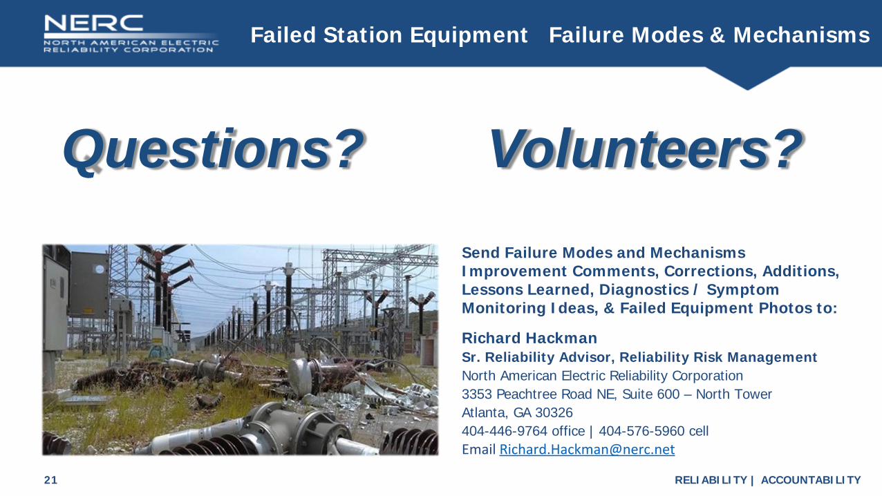
Failed Station Equipment Failure Modes & Mechanisms
Send Failure Modes and Mechanisms Improvement Comments, Corrections, Additions, Lessons Learned, Diagnostics / Symptom Monitoring Ideas, & Failed Equipment Photos to:
Richard HackmanSr. Reliability Advisor, Reliability Risk ManagementNorth American Electric Reliability Corporation3353 Peachtree Road NE, Suite 600 – North TowerAtlanta, GA 30326404-446-9764 office | 404-576-5960 cellEmail [email protected]
Questions? Volunteers?