fall 2012 portfolio
DESCRIPTION
My fall 2012 student architecture portfolioTRANSCRIPT

Shawn BackstromF a l l 2 0 1 2 A r c h i t e c t u r e P o r t f o l i o

Light (re)CycleFabricating a Textiled Lantern
Reciprocal AssemblyExploring Narrative through Cinematic Architecture
Augmented PhotographyDefining Architectonic Terms through a Photographic Lens
Unpacking Sullivan Reconstructing a Louis Sullivan Detail
Contents
Exploration // Manipulation
Repetition // Variation
Final Assembly
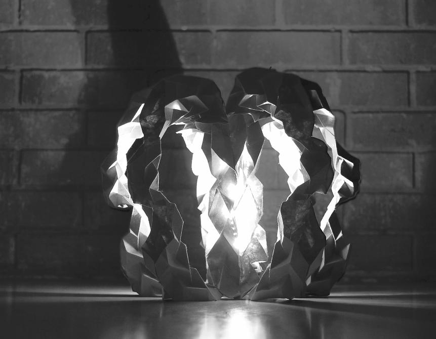
Light (re)CycleF a b r i c a t i n g a Te x t i l e d L a n t e r n
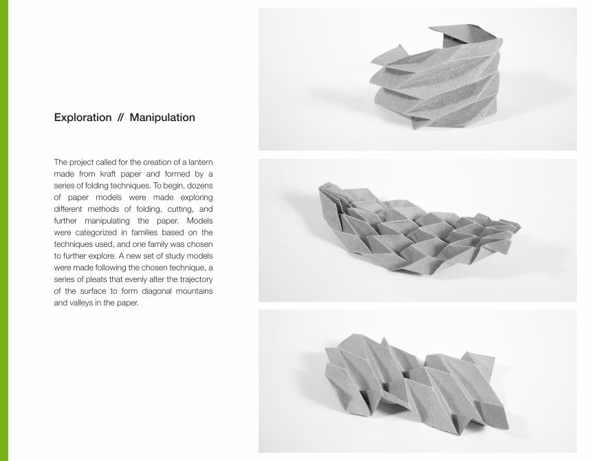
Exploration // Manipulation
The project called for the creation of a lantern made from kraft paper and formed by a series of folding techniques. To begin, dozens of paper models were made exploring different methods of folding, cutting, and further manipulating the paper. Models were categorized in families based on the techniques used, and one family was chosen to further explore. A new set of study models were made following the chosen technique, a series of pleats that evenly alter the trajectory of the surface to form diagonal mountains and valleys in the paper.
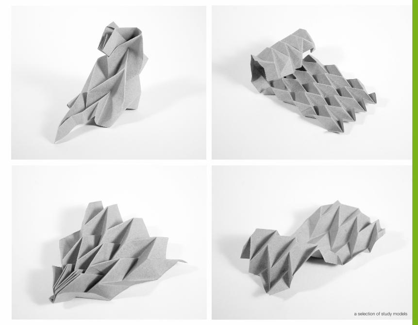
a selection of study models

Repetition // Variation
A single module was chosen from the assortment of paper models to use as the basic unit of the textile. Multiple modules were attached at the ends to form a repeated chain of pleated paper. The module was then manipulated in scale to create variation. The modified module was inserted between larger modules in the chain, creating a repetitive figure that alternates in size. Further studies were done experimenting with the attachment of multiple chains as well as changes to the formation of the chain.
[ b ] single module
[ c ] three modules attached and rotated to form a corkscrew
[ d ] multiple modules attached to form a chained textile
[ e ] interlocking rings formed by a repetition of modules that vary in size
[ a ] connection of three separate module chains

[ e ] interlocking rings formed by a repetition of modules that vary in size

Final Assembly
To arrive at the final design of the lantern, six chains were constructed consisting of a smaller module nestled between two larger modules. These chains were then attached to both ends of a core unit that continued the pleated pattern along its spinal form to create six complete cycles. A small light was inserted at the base of the core, and holes were carved at several points in the core to allow light to permeate through the lantern.

fold fold + unfold pleat + cut bend attach sew
fold fold + unfold pleat bend
cut + fold
cut
insert
attach
[ core construction ]
[ arm construction ]

Film Analysis // Diagramming
Developing an Emotive Palette
Sectional Studies
Sectional Assembly
Final Assembly
Reciprocal AssemblageE x p l o r i n g N a r r a t i v e t h r o u g h C i n e m a t i c A r c h i t e c t u r e
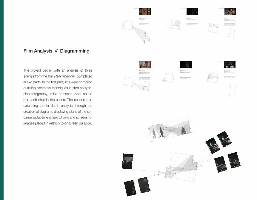
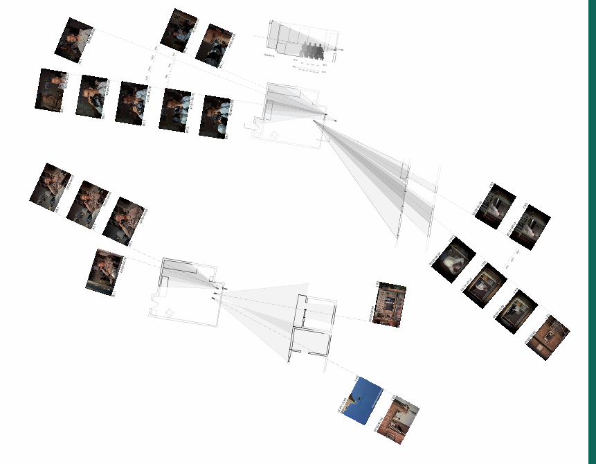
Film Analysis // Diagramming
The project began with an analysis of three
scenes from the film Rear Window, completed
in two parts. In the first part, lists were compiled
outlining cinematic techniques in shot analysis,
cinematography, mise-en-scene and sound
per each shot in the scene. The second part
extending the in depth analysis through the
creation of diagrams displaying plans of the set,
camera placement, field of view and screenshot
images placed in relation to onscreen duration.
A
A
A1.1
A3.1 1:46:54-1:47:04
1:47:07-1:47:09
C5.1
C7.1
1:47:22-1:47:26
1:47:31-1:47:32
D4.
11:
47:0
9-1:
47:2
2
B6.
1
B2.
1
1:47
:04-
1:47
:07
1:47
:26-
1:47
:31
Section A
C
D
A
B
B2.10:04:18-0:04:28
The shot is a POV from LB’s perspective. LB continues to listen to the man on the phone as he watches two of his neighbors through his window. The two women are speaking and hanging up laundry. The voice on the phone is revealed to be LB’s editor, Goddison.
Editing: Cut from Shot 1Cinematography: Long shot POV, camera slightly tilted up aimed at LB’s neighborsSound: neighbors speaking, LB and Goddison talkingMise-en-scene: apartment building, towels, sunlight
B2.10:39:55-0:39:59
The shot is a POV from LB’s perspective. LB watches a man cleaning the inside of a briefcase inside of his apartment.
Editing: Cut from Shot 1Cinematography: Extremely long shotSound: ambient city noise, pianoMise-en-scene: apartment complex, interior of apartment, fire escape
D4.11:47:09-1:47:22
The door opens and Thorwauld slowly enters the apartment. His eyes are illuminated by a strip of light coming from the window. He closes the door behind him and stares at LB.
Editing: Cut from Shot 3Cinematography: Close-up of ThorwauldSound: door opening, ambient noiseMise-en-scene: glasses, light from hallway
C5.11:47:22-1:47:26
LB sits in the darkness and doesn’t move. No one speaks. There is high tension in the shot as LB and Thorwauld finally meet face to face.
Editing: Cut from Shot 4Cinematography: Long shot of LBSound: ambient noiseMise-en-scene: cast, wheelchair, shadows from moonlight coming through the window
C5.10:04:37-0:04:45
LB continues to look up as he is talking on the phone. He moves his gaze down as the sound of the helicopter fades away. LB says that he will not be out of his cast until next Wednesday. Music fades in and LB looks up out of his window.
Editing: Cut from Shot 4Cinematography: Medium Shot of LB sitting in his apartmentSound: LB and Goddison’s voices, radio music, murmur of helicopterMise-en-scene: Photographs, books, apartment furniture
C9.10:42:35-0:42:39
LB brings the camera down slightly and peers over the top of it through the window. He quickly raises it back to his eye.
Editing: Cut from Shot 8Cinematography: Close-up of LBSound: ambient city noiseMise-en-scene: camera lens, camera, apartment furniture
A
A
Section A
A1.
1
39:4
8-39
:55
C2.1
39:55-39:59
B3.
139
:59-
40:3
7
C4.1
40:37-40:49B
5.1
40:4
9-41
:01
C6.1
41:01-41:03
C6.2
41:06-41:09
C8.1
42:15-42:35
C10.1
42:39-42:50
B7.
141
:09-
41:1
6
B7.
2
41:2
0-41
:51
B7.
341
:57-
42:1
5
B9.
142
:35-
42:3
9
B11
.1
42:5
0-42
:59
0:01
0:02
0:03
0:04
0:01
0:03
0:05
0:02
0:03
0:01
0:010:02
0:030:04
B7.2
B7.1B7.2
B7.30:05 0:060:04
0:02 0:030:01
B1.
1
04:0
2-04
:18
A3.
1
04:2
8-04
:31
A5.
1
04:3
7-04
:45
A7.
1
04:5
3-04
:55
C6.1
04:45-04:53
D2.1
04:18-04:28
D4.1
04:31-04:37
C
D
A B
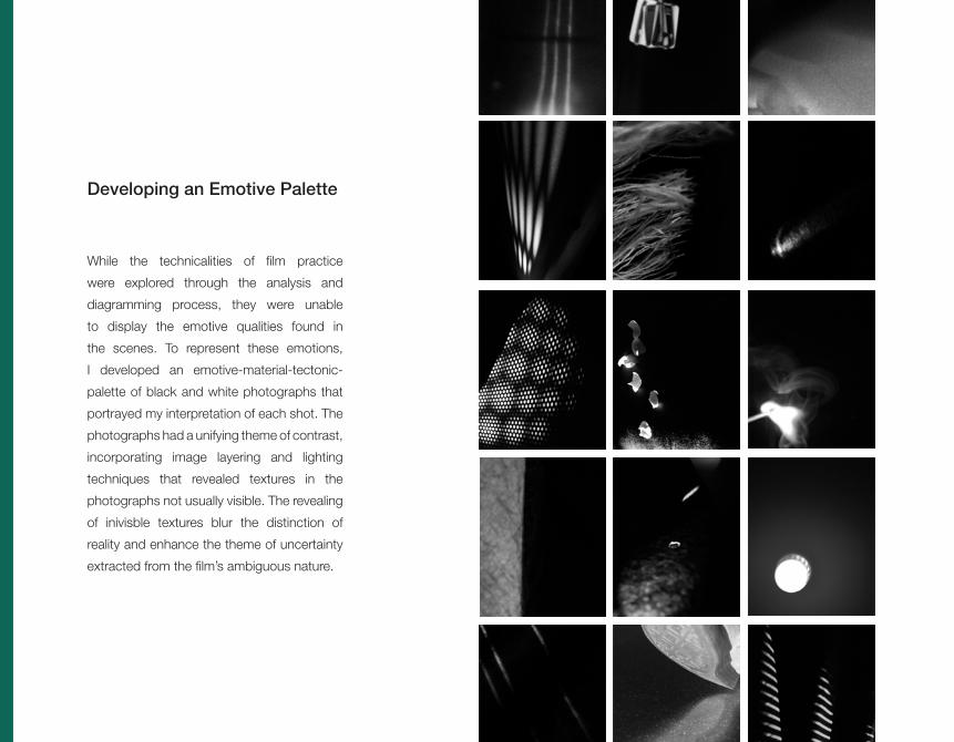
Developing an Emotive Palette
While the technicalities of film practice
were explored through the analysis and
diagramming process, they were unable
to display the emotive qualities found in
the scenes. To represent these emotions,
I developed an emotive-material-tectonic-
palette of black and white photographs that
portrayed my interpretation of each shot. The
photographs had a unifying theme of contrast,
incorporating image layering and lighting
techniques that revealed textures in the
photographs not usually visible. The revealing
of inivisble textures blur the distinction of
reality and enhance the theme of uncertainty
extracted from the film’s ambiguous nature.

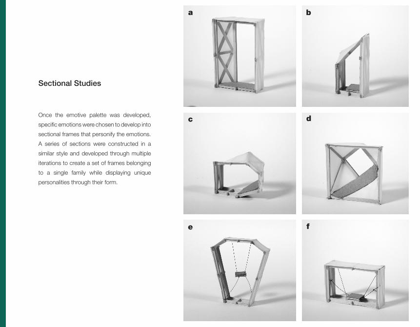
Sectional Studies
Once the emotive palette was developed,
specific emotions were chosen to develop into
sectional frames that personify the emotions.
A series of sections were constructed in a
similar style and developed through multiple
iterations to create a set of frames belonging
to a single family while displaying unique
personalities through their form.
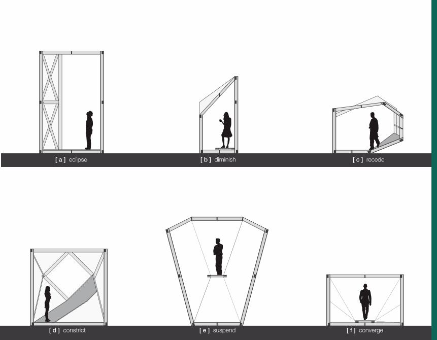
[ a ] eclipse [ b ] diminish [ c ] recede
[ d ] constrict [ e ] suspend [ f ] converge
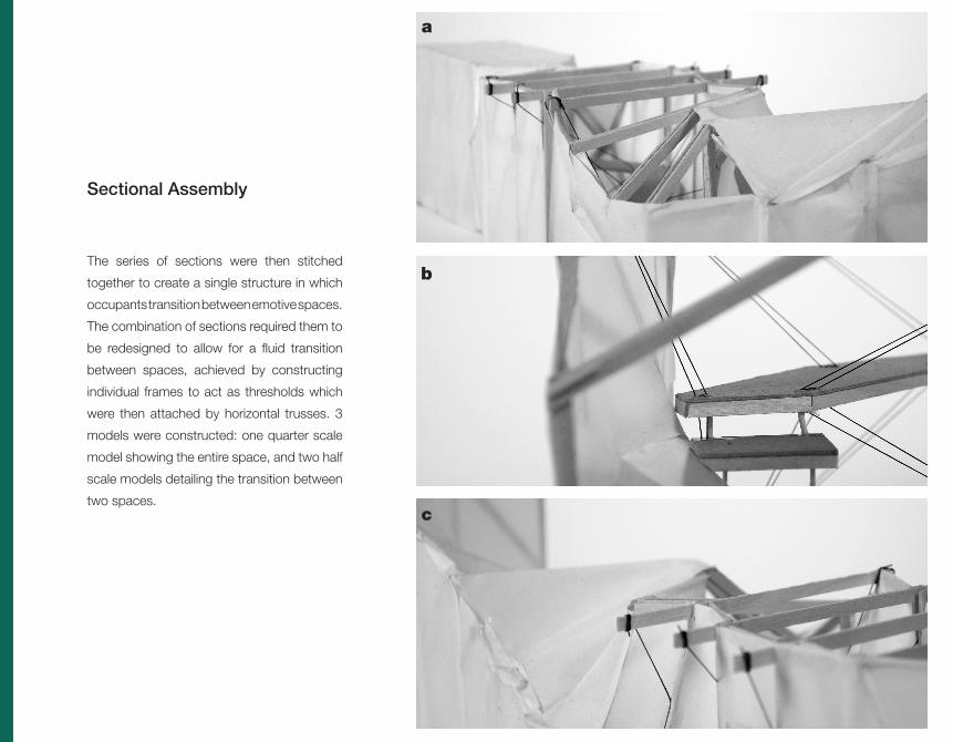
Sectional Assembly
The series of sections were then stitched
together to create a single structure in which
occupants transition between emotive spaces.
The combination of sections required them to
be redesigned to allow for a fluid transition
between spaces, achieved by constructing
individual frames to act as thresholds which
were then attached by horizontal trusses. 3
models were constructed: one quarter scale
model showing the entire space, and two half
scale models detailing the transition between
two spaces.
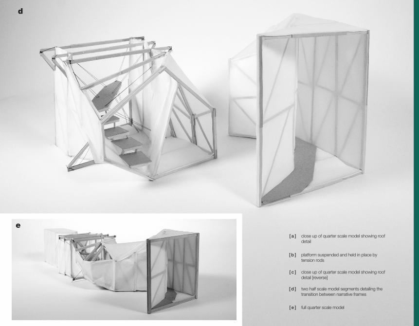
[ b ] platform suspended and held in place by tension rods
[ c ] close up of quarter scale model showing roof detail [reverse]
[ d ] two half scale model segments detailing the transition between narrative frames
[ e ] full quarter scale model
[ a ] close up of quarter scale model showing roof detail

Final Assembly
The design of the space went through several
interations before arriving at a final design.
Project requirements also called for the
inclusion of three specific funcitonal identities:
an enclosed space, a semi-enclosed space,
and an open space. Modifications were
made to individual frames as well as the truss
system, strengthening the structure while
adapting to the project requirements. The
primary modifaction was the addition of a
panel system that repeated itself throughout
the structure. The panelling system was
developed across the exterior facades while
a continuous slate extends along the interior,
incorporating the contrast explored in the
emotive palette as a critical component of the
final design.

[ b ] view from initial threshold
[ c ] east facade panelling detail
[ d ] rotating roof frame detail
[ e ] full quarter scale model
[ f ] west facade
[ g ] east facade
[ a ] cables extending along the west facade

The final model was also required to have an
animate portion that responded to some sort
of condition. Drawing inspiration from earlier
models, I converted part of the structure
into a mechanism consisting of a series of
platforms that lower when stepped on. The
platforms are supported by elastic bands
(hidden within the posts of the structure) and
tension rods that reconnect to the platform
structure at a point on the exterior. The cables
redirect the downward force exerted on the
platform to the exterior point of equilibrium,
allowing the platform to lower level with
the ground. The cable extend up along the
exterior and attach to three roof panels that
raise as the platform lowers, allowing light to
enter the room in horizontal bands.

A
A
[ b ] half scale animate segment model
[ c ] platform attachment + cable connection
[ d ] roof panel attachment [video screenshots]
[ e ] mechanism diagram showing redistribution of weight + roof panel opening [video screenshots]
[ f ] plan
[ g ] section a
[ a ] roof panels opening on model


Balance
Continuity
Space
Rhythm
Similarity
Augmented PhotographyDef in ing Archi tectonic Terms through a Photographic Lens

This set of photographs was developed
through a three part process, the first of
which required me to write my own definitions
for architectonic terms. Once I had formed
definitions that adequetely described the
terms, photographs were taken to create a
graphic representation of the terms. Two of
these photographs were then augmented
through the addition of vector graphics that
referred to and enhanced the definitions of
the terms.

Balance
A harmonious relationship between interacting
elements formed by an equal distribution of
weight

Continuity
An uniterrupted connection of elements

Space
An area which objects pass through in any
dimension
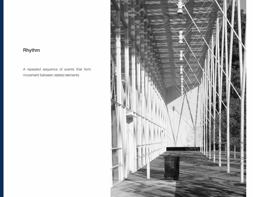
Rhythm
A repeated sequence of events that form
movement between related elements
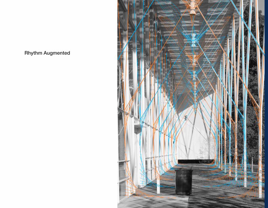
Rhythm Augmented
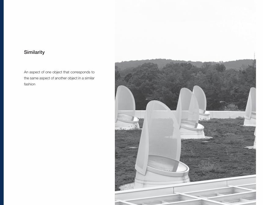
Similarity
An aspect of one object that corresponds to
the same aspect of another object in a similar
fashion
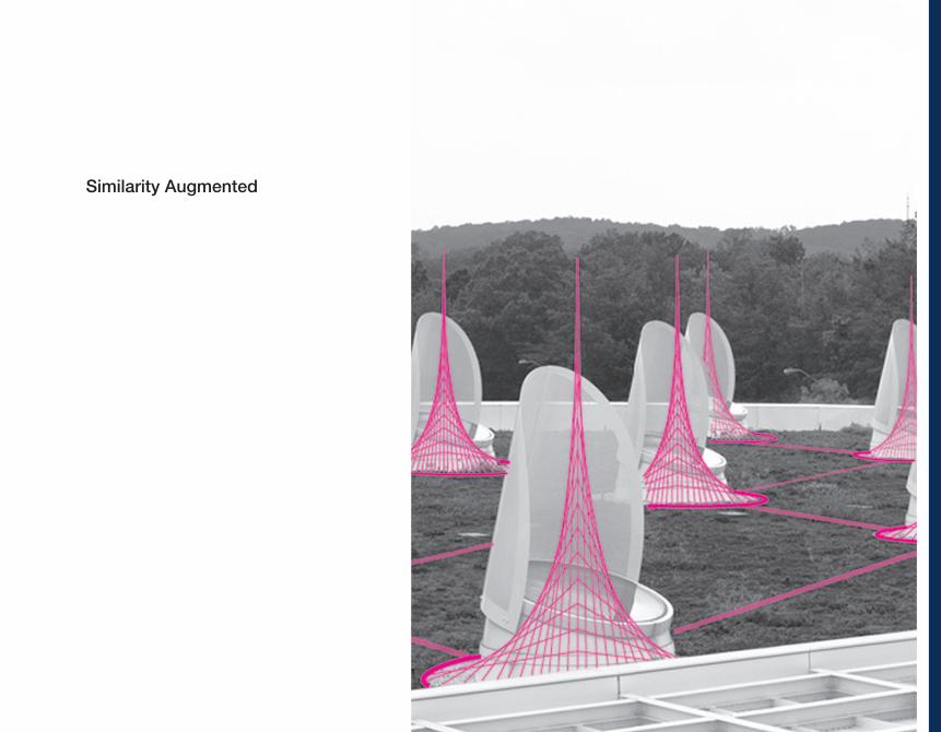
Similarity Augmented
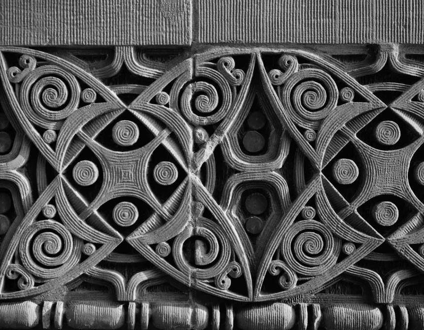

Geometric Reconstruction
Original Detial
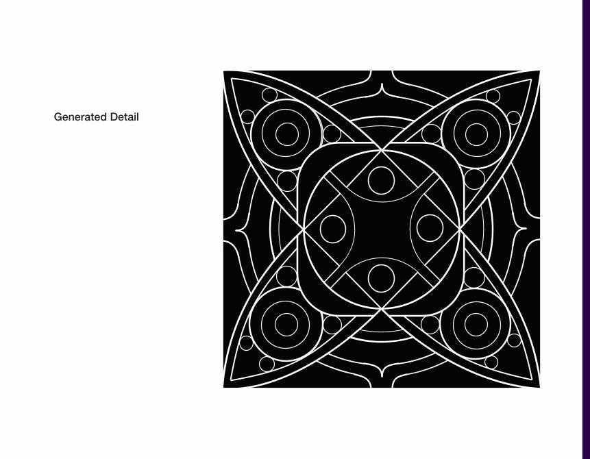
Generated Detail
Unpacking SullivanR e c o n s t r u c t i n g a L o u i s S u l l i v a n D e t a i l
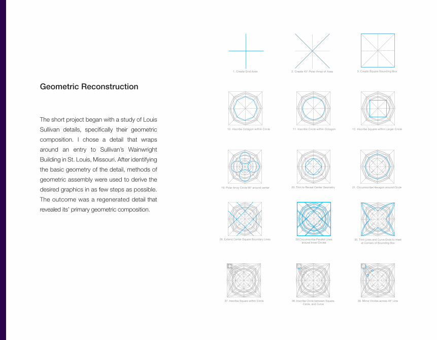
Geometric Reconstruction
The short project began with a study of Louis
Sullivan details, specifically their geometric
composition. I chose a detail that wraps
around an entry to Sullivan’s Wainwright
Building in St. Louis, Missouri. After identifying
the basic geometry of the detail, methods of
geometric assembly were used to derive the
desired graphics in as few steps as possible.
The outcome was a regenerated detail that
revealed its’ primary geometric composition.
1. Create Grid Axes 2. Create 45° Polar Array of Axes 3. Create Square Bounding Box 4. Inscribe Octagon witihin Box 5. Inscribe Circle within Octagon 6. Inscribe Octagon within Circle 7. Inscribe Circle within Octagon 8. Inscribe Square within Larger Circle 9. Inscribe Circle within Square
10. Inscribe Octagon within Circle 11. Inscribe Circle within Octagon 12. Inscribe Square within Larger Cricle 14. Inscribe Rotated Square within Circle13. Inscribe Circle within Square 15. Inscribe Circle within Square 16. Inscribe Square within Circle 17. Inscribe Rotated Square within Square 18. Inscribe Circle between Center Square and Second Circle
19. Polar Array Circle 90° around center 20. Trim to Reveal Center Geometry 21. Circumscribe Hexagon around Circle 22. Inscribe Square within Hexagon 23. Round Corners to MatchCurve of Circle
24. Inscribe Rotated Square within Inner Geometry
27. Polar Array Circle 90°to Complete Center Detail
26. Inscribe Circle within Square25. Inscribe Sqaure withinRotated Square
31. Inscribe Circle between Two Curves 32. Inscribe Circle between OuterCircle and Inner Circle
33. Inscribe Circle between OuterOctagon and Inner Octagon
34. Inscribe Circle Inside Space betweenCurve, Circle, and Square
35. Inscribe Square between BoundingBox and Corner of Inner Square
41. Trim Outer Circles and Octagons 42. Curve Octagon Edges AlongX and Y Axes
43. Remove Octagons and Gridsto Reveal Final Geometry
36. Inscribe Circle within Square
37. Inscribe Square within Circle40. Polar Array Circles 90°
38. Inscribe Circle between Square,Circle, and Curve
39. Mirror Circles across 45° Line
28. Extend Center Square Boundary Lines 30. Trim Lines and Curve Ends to meetat Corners of Bounding Box
29.Circumscribe Parallel Linesaround Inner Circles
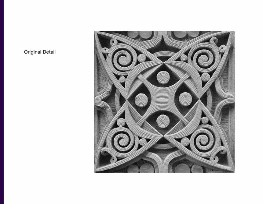
Original Detail
Generated Detail