fall 2012 studio: diffcult synthesis
DESCRIPTION
Works from the course of the semester with partner Alex FischerTRANSCRIPT
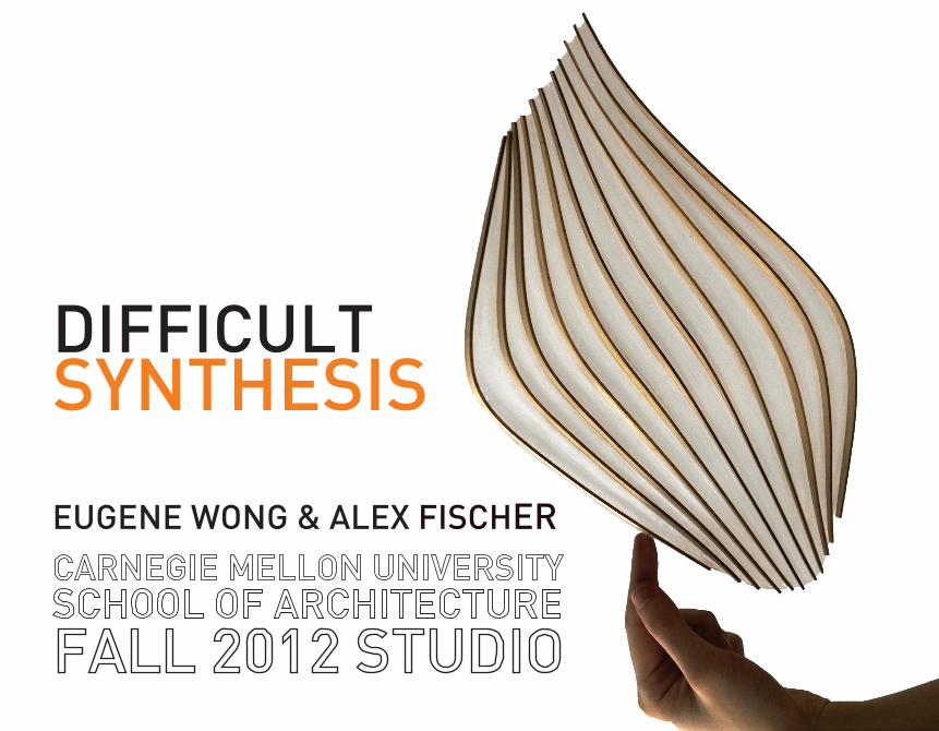
DIFFICULT
EUGENE WONG & ALEX FISCHER
SYNTHESIS
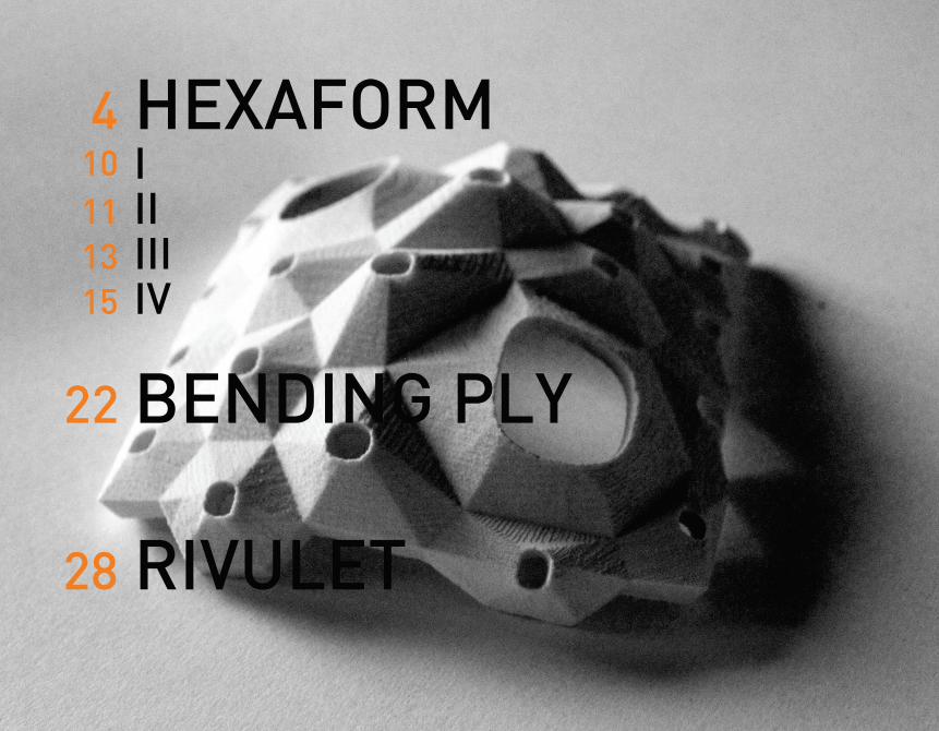
4 HEXAFORM
BENDING PLY
IIIIII
15 IV
28 RIVULET
101113
22
Situations atThe Envelope
SynthesizedArchitectural
Project
Materials
Fabrication
Natural FormStudies
DigitalProcesses
ProgramRequirements
StructuralPerformance
Parameters
Casted Material Sheet Material
Woven MaterialHandProcesses
BendingSurface
MaterialManipulation
MaterialPrototyping
SiteAnalysis
MaterialComposition
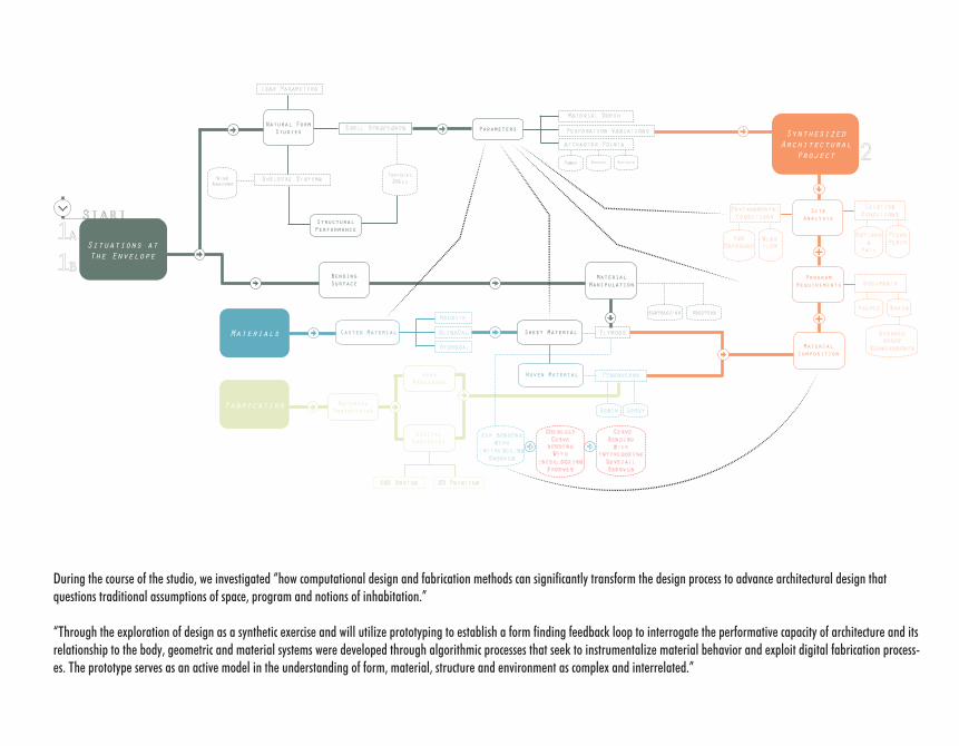
During the course of the studio, we investigated “how computational design and fabrication methods can significantly transform the design process to advance architectural design that questions traditional assumptions of space, program and notions of inhabitation.”
“Through the exploration of design as a synthetic exercise and will utilize prototyping to establish a form finding feedback loop to interrogate the performative capacity of architecture and its relationship to the body, geometric and material systems were developed through algorithmic processes that seek to instrumentalize material behavior and exploit digital fabrication process-es. The prototype serves as an active model in the understanding of form, material, structure and environment as complex and interrelated.”
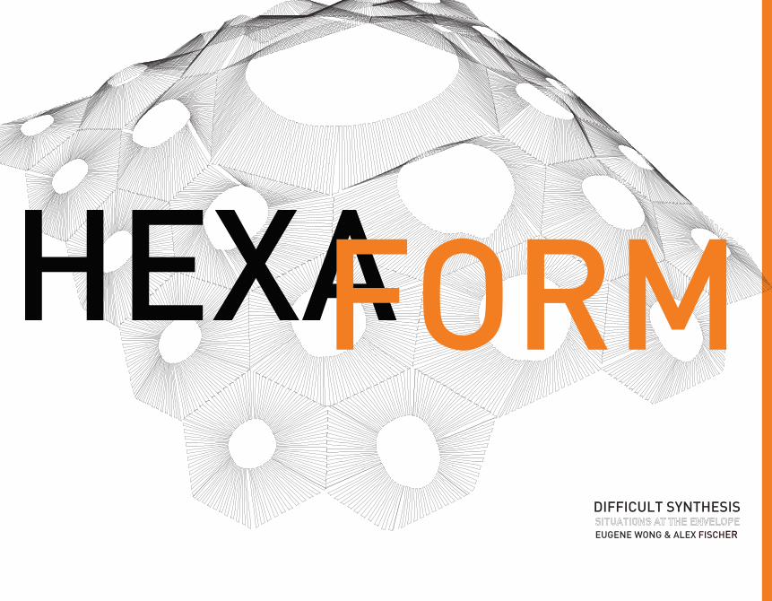
HEXAFORMDIFFICULT SYNTHESIS
EUGENE WONG & ALEX FISCHER
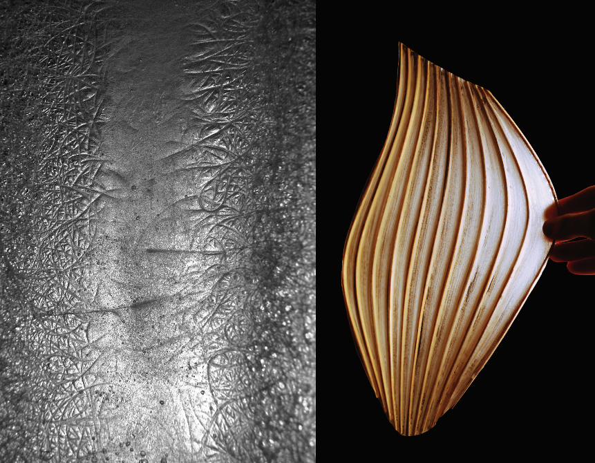
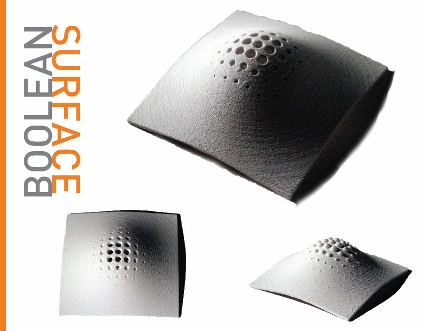
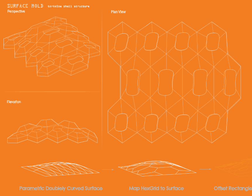
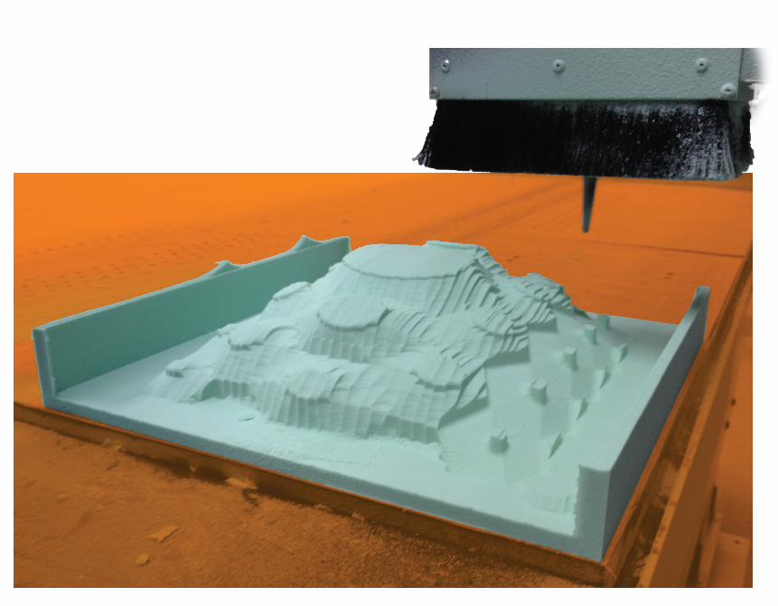
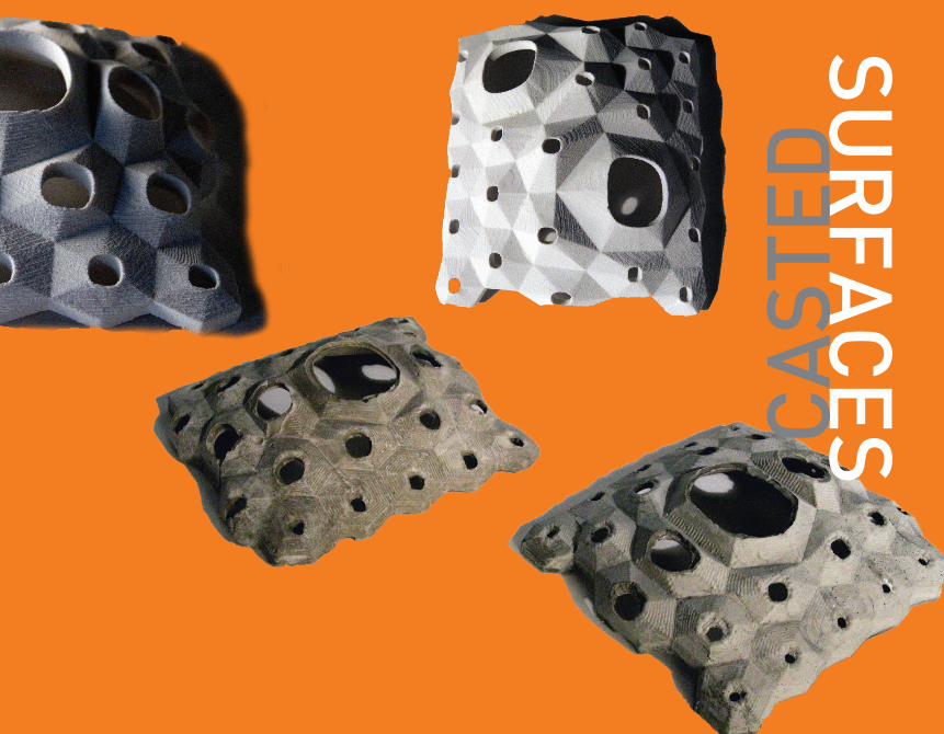
Hexaform began with the study of natural forms and the systems that they emerge from. From our initial explorations, we decided the shell of a tortoise contained many interesting properties that could inform a castable surface. The size and number of plates, extrusion height, and number of concentric rings are all variables that affect the shell’s performance. As the plates get higher on the shell, their ridg-es grow in height, creating a spiking effect. In addition, the hexagon shaped plates get deformed as they move down towards the edge of the shell. The concentric rings on each plate are much like rings of a tree. The rings grow out from the cen-ter each year, allowing a reading of the tortoise’s age from sight alone. Hexaform attempts to recreate this structure, with corresponding variables, with apertures to regulate light.
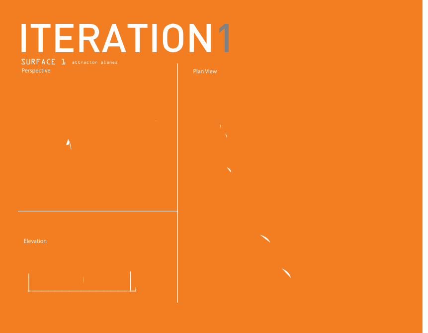
ITERATION1SURFACE 1
Plan View
Elevation
Perspectiveattractor planes
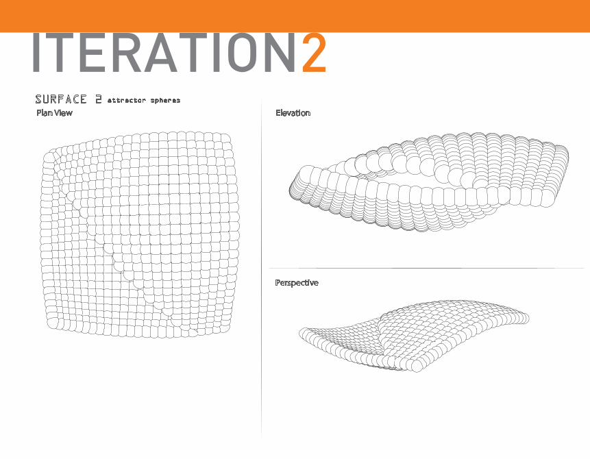
ITERATION2
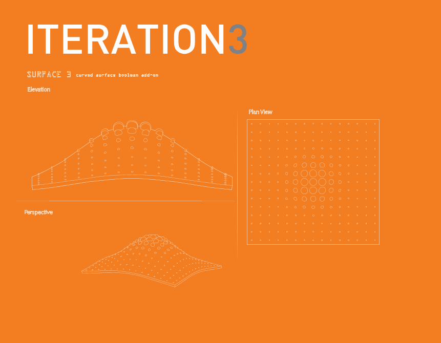
ITERATION3
SUR
FAC
E
BO
OLE
AN
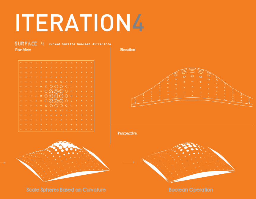
ITERATION4
1/8”
1/8”
1/2”
1/2”
1” = 1”
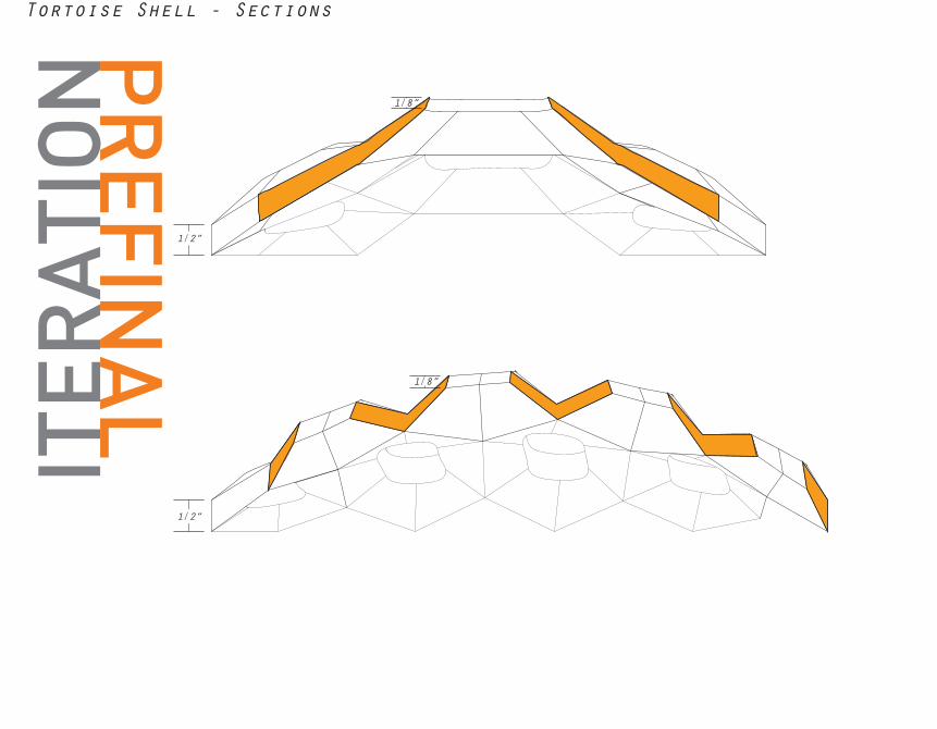
Tortoise Shell - SectionsPR
EFINA
L
ITER
ATI
ON
1/8”
1/8”
1/2”
1/2”
1” = 1”
Tortoise Shell - Sections
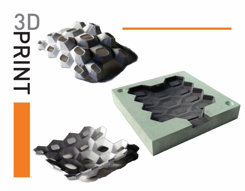
3DPR
INT
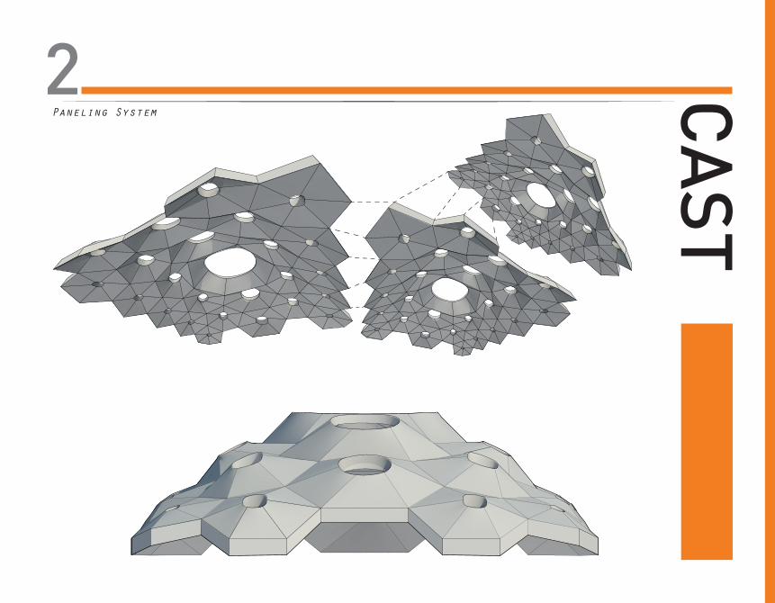
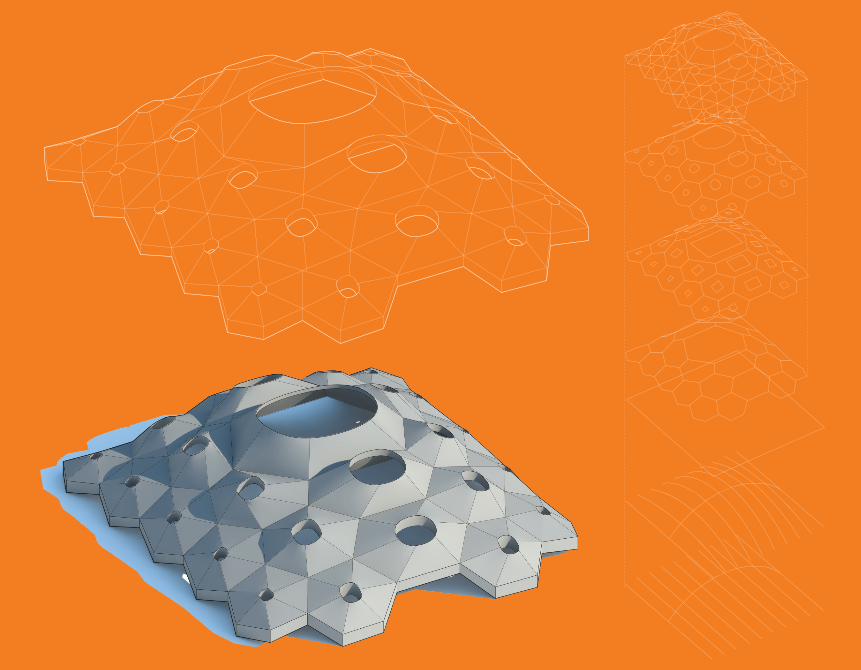
Paneling System
2 CA
ST
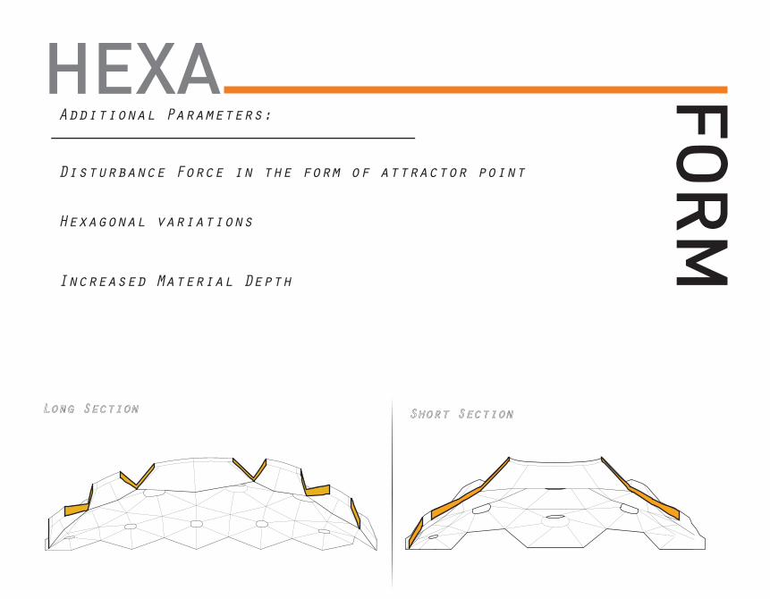
HEXA FOR
MAdditional Parameters:
Disturbance Force in the form of attractor point
Hexagonal variations
Increased Material Depth
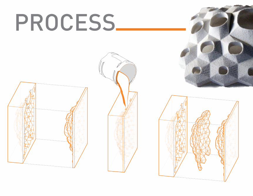
PROCESS
SUR
FAC
ESCA
STED
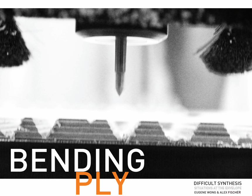
BENDINGPLY DIFFICULT SYNTHESIS
EUGENE WONG & ALEX FISCHER
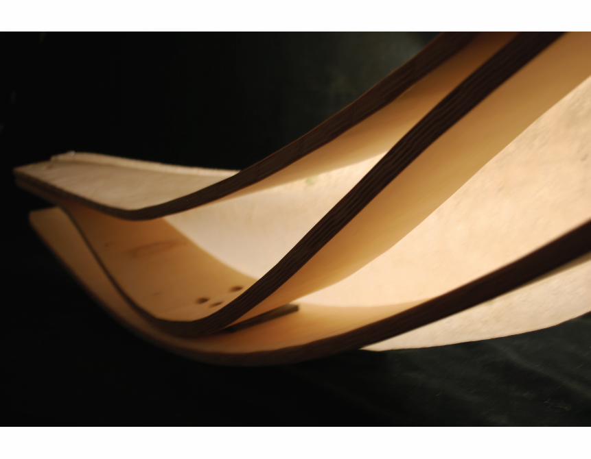
This project explores the ways and means by which plywood bends. Simple tests were devised to explore how the depth and width of a kerf affects the flexibility and strength of plywood. The first test was a gradient of depths and widths, expanding from the center of the sheet, with the deepest and wid-est cuts occurring at the center. The second test was the opposite, with the deepest and widest cuts at the ends. From these two tests, it was determined that shallow-wide kerfs offered little flexibility but great stability. The deep-wide kerfs tore easily. Deep-thin kerfs caused the wood to snap at those points, and shallow-thin kerfs restricted bending too much. The sweet spot seemed to be kerf with a 1/16th inch “skin” with a width of around half-an-inch. A third test was devised to determine whether the depth of the cut could dampen the effect of creating the kerfs against the grain of the bottom layer of plywood. As the kerfs go more-and-more against the grain, the depth is increased. This test was successful in that the plywood was able to twist in a consistent way not possible with straight kerfs or even-depth kerfs. These tests were leading to determine if kerfs could be made so that the plywood bent in a predetermined, predictable way. To this end, the zip-shape method of bending wood, innovated by Schindler Salmeron was explored. His method allows the creator to mill a flat sheet of plywood into two sides, and when the sides are pressed together, will form a given curve. The method essentially works by spacing the teeth such that the only way the two sides will ever fit back together is if they are in the predetermined curve shape. A script was written in grasshopper and revised throughout the course of the project. The zip-shape method’s real value is in its ability to bend plywood without the need for mold around which to bend the wood, as is used in steam bending. This allows custom bent wood pieces to vary, without any additional material or labor. In addition, the final result is a curved piece of ply-wood that is stronger than could be created using steam bending.
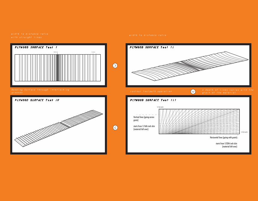
width to distance ratiowith straight lines
Bending Surface through interlocking grooves
1/8th inch 2 inches
z depth of lines varies with the grain of the materialcontour toolpath operation
width to distance ratio
1/16 inch
1/32 inch
Vertical lines (going across grain)
starts from 1/16th inch skin (material left over)
Horizontal lines (going with grain)
starts from 1/32th inch skin (material left over)
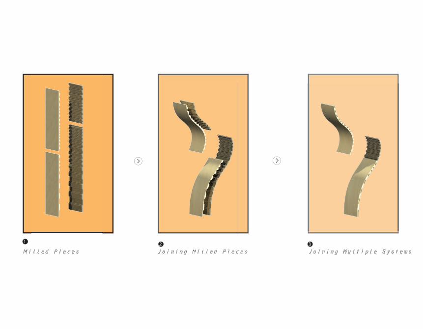
1 2 3
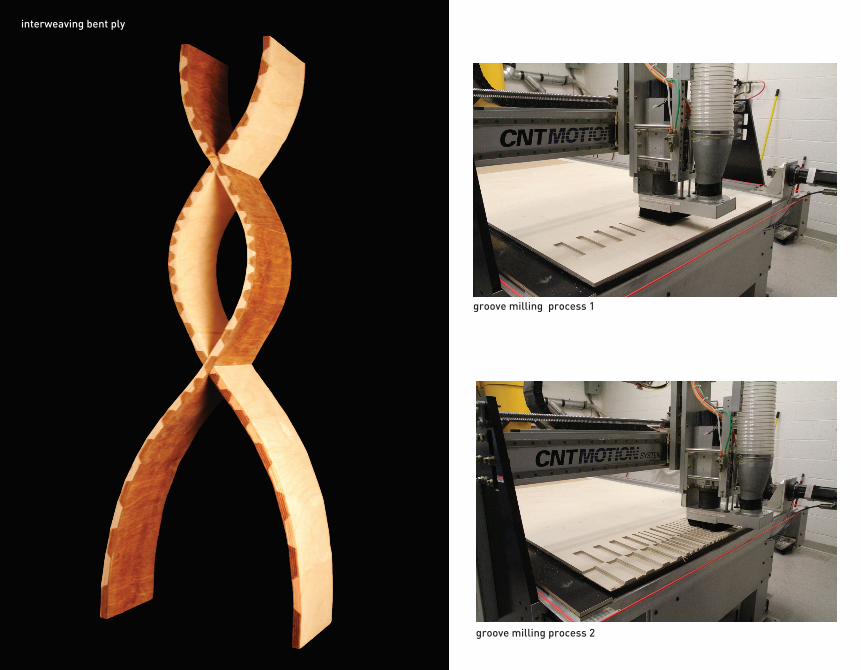
groove milling process 1
groove milling process 2
interweaving bent ply
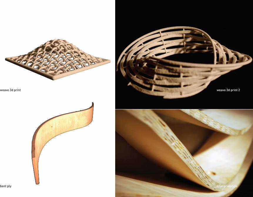
weave 3d print
bent ply
weave 3d print 2
final prototype
RIVULETSTUDIO: DIFFICULT SYNTHESISEUGENE WONG & ALEX FISCHER
LET
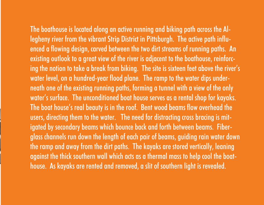
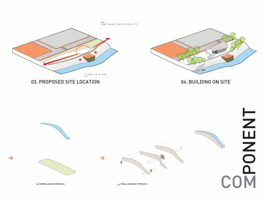
The boathouse is located along an active running and biking path across the Al-legheny river from the vibrant Strip District in Pittsburgh. The active path influ-enced a flowing design, carved between the two dirt streams of running paths. An existing outlook to a great view of the river is adjacent to the boathouse, reinforc-ing the notion to take a break from biking. The site is sixteen feet above the river’s water level, on a hundred-year flood plane. The ramp to the water dips under-neath one of the existing running paths, forming a tunnel with a view of the only water’s surface. The unconditioned boat house serves as a rental shop for kayaks. The boat house’s real beauty is in the roof. Bent wood beams flow overhead the users, directing them to the water. The need for distracting cross bracing is mit-igated by secondary beams which bounce back and forth between beams. Fiber-glass channels run down the length of each pair of beams, guiding rain water down the ramp and away from the dirt paths. The kayaks are stored vertically, leaning against the thick southern wall which acts as a thermal mass to help cool the boat-house. As kayaks are rented and removed, a slit of southern light is revealed.
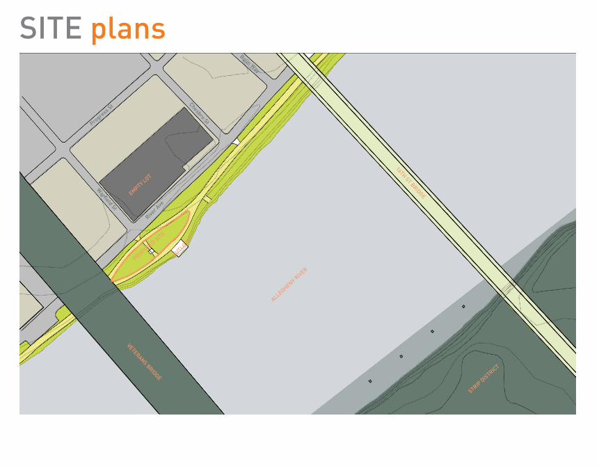
PROPOSED SITE
OUTLOOKEMPTY LOT
River A
ve
Progre
ss St
Warfield St
Chesbro St
Bolin Way
16TH ST BRIDGE
VETERANS BRIDGE
ALLEGHENY RIVER
STRIP D
ISTRICT
SITE plans
a
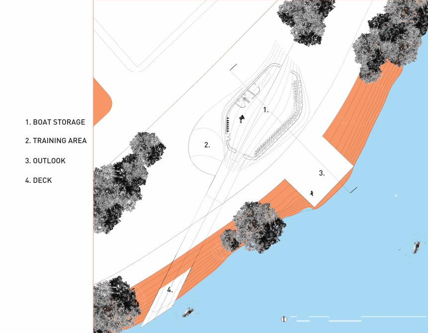
1. BOAT STORAGE
2. TRAINING AREA
3. OUTLOOK
4. DECK
1.
2.
3.
4.
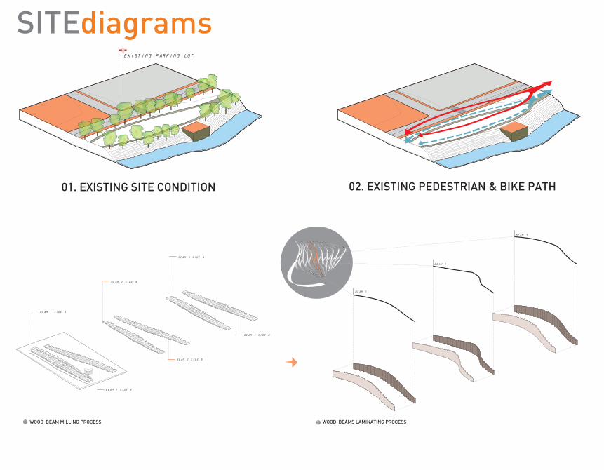
EXISTING PARKING LOT
01. EXISTING SITE CONDITION 02. EXISTING PEDESTRIAN & BIKE PATH 03. PROPOSED SITE LOCATION 04. BUILDING ON SITE
VIEWS TO RIVER
CONTINUOUS ACCESSIBILITY
BEAM 1 SIDE A
BEAM 1 SIDE B
BEAM 1
BEAM 2
BEAM 3
BEAM 2 SIDE A
BEAM 2 SIDE B
BEAM 3 SIDE A
BEAM 3 SIDE B
WOOD BEAM MILLING PROCESS 2 41 WOOD BEAMS LAMINATING PROCESS FIBERGLASSING PROCESS3 FINAL ASSEMBLY PROCESS
SITEdiagrams
EXISTING PARKING LOT
01. EXISTING SITE CONDITION 02. EXISTING PEDESTRIAN & BIKE PATH 03. PROPOSED SITE LOCATION 04. BUILDING ON SITE
VIEWS TO RIVER
CONTINUOUS ACCESSIBILITY
BEAM 1 SIDE A
BEAM 1 SIDE B
BEAM 1
BEAM 2
BEAM 3
BEAM 2 SIDE A
BEAM 2 SIDE B
BEAM 3 SIDE A
BEAM 3 SIDE B
WOOD BEAM MILLING PROCESS 2 41 WOOD BEAMS LAMINATING PROCESS FIBERGLASSING PROCESS3 FINAL ASSEMBLY PROCESS COM
PO
NEN
T
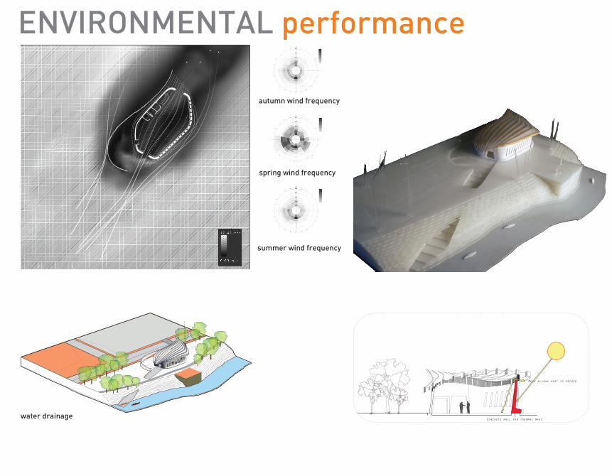
autumn wind frequency
spring wind frequency
summer wind frequency
ENVIRONMENTAL performance
CHANNELING RAINWATER water drainage Concrete wall for thermal mass
Mesh allows heat to escape
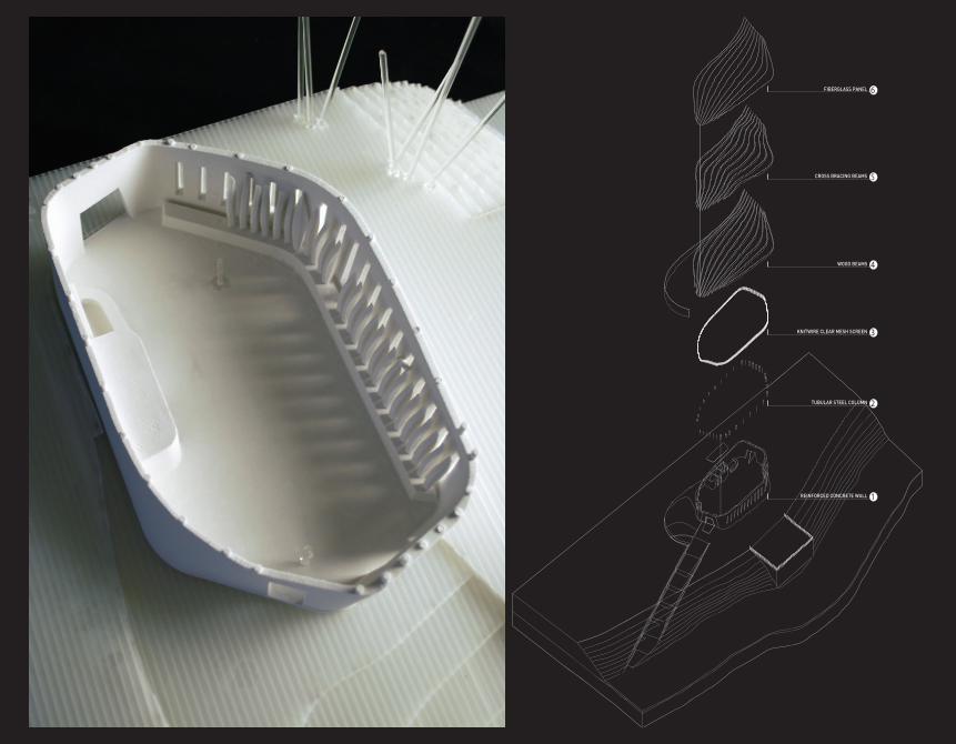
KNITWIRE CLEAR MESH SCREEN 3
TUBULAR STEEL COLUMN 2
REINFORCED CONCRETE WALL 1
WOOD BEAMS 4
CROSS BRACING BEAMS 5
FIBERGLASS PANEL 6
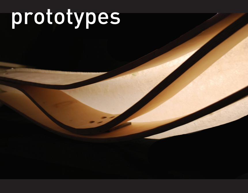
prototypes
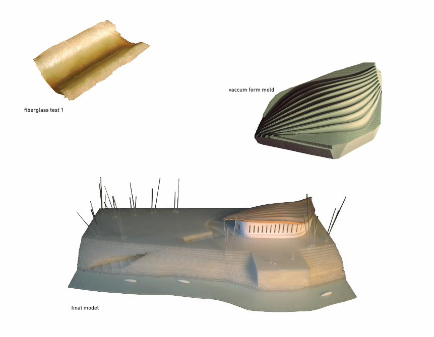
fiberglass test 1
vaccum form mold
final model
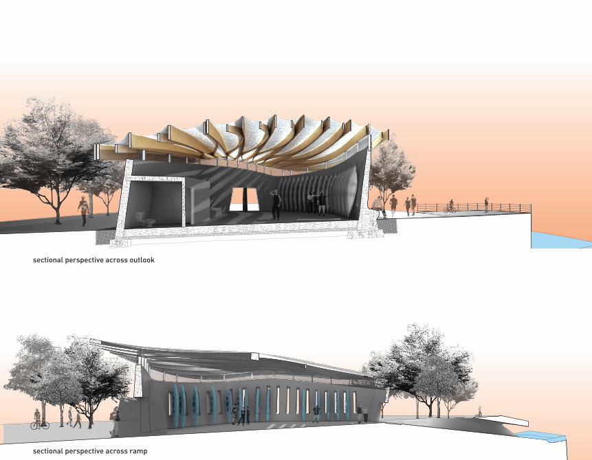
sectional perspective across outlook
sectional perspective across ramp
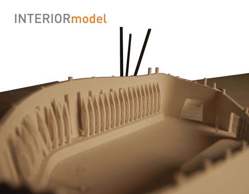
INTERIORmodel