fall 2014 lab 1 module, cell biology genetics lab
DESCRIPTION
Lab 1, Cell biology, study of Nematodes and epithelial skin cells. Growth and Development of nematode life cycleTRANSCRIPT

1
Lab Safety and Emergency Information The safety of students and staff is paramount. Safe laboratory practices are incorporated into lab procedures and will be supplemented with instructor directions. The following information and precautions should help reduce the chances of lab accidents or injuries and will help you respond to emergencies if they arise. Read this information carefully and leave this page in your lab manual. Sign and turn in the signature page of lab safety and emergency information. Give it to your lab instructor on your first day of class. Lab Safety Practices and Instructions: Ø Carefully follow lab procedures and your instructor’s directions. Ask your instructor for assistance if
you are unsure about lab procedures and safety precautions. Ø Use common sense and be aware of your surroundings and what others are doing. Ø Do not eat, drink, or apply makeup in the laboratory. Always wash your hands before leaving lab. Ø Wear appropriate eye protection while doing lab activities that require it. Check the lab syllabus for
the dates of labs when safety glasses or goggles are required and follow your instructor’s directions about their use and care.
Ø When asked to do so, collect chemical wastes in specially marked waste containers to allow proper disposal. Your instructor will give you specific chemical waste disposal instructions.
Ø Put broken glassware in the lab’s "Broken Glass" collection bucket. Never discard broken glass or other sharp objects in lab trash bins.
Ø Discard contaminated microscope slides, razor blades, and hazardous materials other than chemicals in the red biohazard "Sharps" container or other biohazard containers in lab, when asked to do so.
Ø Bare feet are not allowed in lab. Always wear appropriate footwear and clothing in laboratories. Ø Use a fume hood when working with chemicals and/or dusty materials, or whenever instructed to do
so. Ø Use care when working with chemicals, glassware, and equipment to reduce chances of injury or
equipment problems. Ø Inform your lab instructor immediately if you get injured in lab or if you become aware of chemical
spills or lab conditions that could lead to injury. Ø Keep laboratory floors and work surfaces clean and dry. Clean your work area and lab countertop
before leaving class using the provided cleaning solution and supplies. Also, clean and dry microscope slides, cover slips, and other glassware when finished with them and return all materials and supplies to their proper place. All writing and labels should be removed when cleaning glassware. Don’t leave a mess for others to clean up before they can start working!
Ø Material Safety Data Sheets (MSDS) for lab chemicals are available for review in Science 1 room 203 if you want specific chemical information. A chemical’s MSDS identifies its specific hazards, handling precautions, exposure limits, and disposal requirements.
Ø Learn the location of the lab's eyewash. If necessary, use it to flush contaminants from the eyes and face.
Emergency Information: Read and become familiar with the emergency and evacuation information posted near the lab’s exit door. In a lab, building, or campus-wide emergency follow the posted guidelines and your instructor’s directions. Ø Dial 911 from lab phones (located by exit doors) or 278-8400 using cell phones for rapid response
to emergencies (medical, fire, earthquake, etc.). Ø Dial 911, rather than attempting to put out fires where there is a risk of injury. Fire alarm pulls are
located at the ends of the outside hallway. A lab fire extinguisher is for use on minor fires, and then only by capable individuals.
Ø EVACUATION SITES: Science 1's evacuation area for building emergencies is the lawn area south of the Science 1 building between Peters Building and Satellite Student Union. For campus-wide emergencies only, go to O’Neill Park at the corner of Barstow and Woodrow Avenues. Meet at the appropriate evacuation site and remain there so that all building occupants can be accounted for.
Ø Inform your instructor if you have special needs (e.g. visual or mobility impairment) and/or could require assistance in an emergency or have a medical condition that could cause you to fall, sustain other injury, or require assistance.

2
Student’s Name: Lab Day/Time (Print Name)
Lab Safety and Emergency Information Signature Page The safety of students and staff is paramount. Safe laboratory practices are incorporated into lab procedures and will be supplemented with instructor directions. The following information and precautions should help reduce the chances of lab accidents or injuries and will help you respond to emergencies if they arise. Read this information carefully, then sign this page of lab safety and emergency information and give it to your lab instructor on your first day of class. Leave the other copy in your lab manual for future reference. Lab Safety Practices and Instructions: Ø Carefully follow lab procedures and your instructor’s directions. Ask your instructor for assistance if you are unsure about
lab procedures and safety precautions. Ø Use common sense and be aware of your surroundings and what others are doing. Ø Do not eat, drink, or apply makeup in the laboratory. Always wash your hands before leaving lab. Ø Wear appropriate eye protection while doing lab activities that require it. Check the lab syllabus for the dates of labs when
safety glasses or goggles are required and follow your instructor’s directions about their use and care. Ø When asked to do so, collect chemical wastes in specially marked waste containers to allow proper disposal. Your
instructor will give you specific chemical waste disposal instructions. Ø Put broken glassware in the lab’s "Broken Glass" collection bucket. Never discard broken glass or other sharp objects in
lab trash bins. Ø Discard contaminated microscope slides, razor blades, and hazardous materials other than chemicals in the red
biohazard "Sharps" container or other biohazard containers in lab, when asked to do so. Ø Bare feet are not allowed in lab. Always wear appropriate footwear and clothing in laboratories. Ø Use a fume hood when working with chemicals and/or dusty materials, or whenever instructed to do so. Ø Use care when working with chemicals, glassware, and equipment to reduce chances of injury or equipment problems. Ø Inform your lab instructor immediately if you get injured in lab or if you become aware of chemical spills or lab conditions
that could lead to injury. Ø Keep laboratory floors and work surfaces clean and dry. Clean your work area and lab countertop before leaving class
using the provided cleaning solution and supplies. Also, clean and dry microscope slides, cover slips, and other glassware when finished with them and return all materials and supplies to their proper place. All writing and labels should be removed when cleaning glassware. Don’t leave a mess for others to clean up before they can start working!
Ø Material Safety Data Sheets (MSDS) for lab chemicals are available for review in Science 1 room 203 if you want specific chemical information. A chemical’s MSDS identifies its specific hazards, handling precautions, exposure limits, and disposal requirements.
Ø Learn the location of the lab's eyewash. If necessary, use it to flush contaminants from the eyes and face. Emergency Information: Read and become familiar with the emergency and evacuation information posted near the lab’s exit door. In a lab, building, or campus-wide emergency follow the posted guidelines and your instructor’s directions. Ø Dial 911 from lab phones (located by exit doors) or 278-8400 using cell phones for rapid response to emergencies
(medical, fire, earthquake, etc.). Ø Dial 911, rather than attempting to put out fires where there is a risk of injury. Fire alarm pulls are located at the ends of
the outside hallway. A lab fire extinguisher is for use on minor fires, and then only by capable individuals. Ø EVACUATION SITES: Science 1 evacuation area for building emergencies is the lawn area south of the Science 1
building between Peters Building and Satellite Student Union. For campus-wide emergencies only, go to O’Neill Park at the corner of Barstow and Woodrow Avenues. Meet at the appropriate evacuation site and remain there so that all building occupants can be accounted for.
Ø Inform your instructor if you have special needs (e.g. visual or mobility impairment) and/or could require assistance in an emergency or have a medical condition that could cause you to fall, sustain other injury, or require assistance.
I HAVE READ THE LABORATORY SAFETY AND EMERGENCY INFORMATION AND UNDERSTAND MY OBLIGATION TO OBSERVE LAB RULES AND HELP KEEP THE LAB ENVIRONMENT CLEAN AND SAFE FOR OTHERS AND MYSELF. I HAVE RETAINED A COPY OF THIS INFORMATION IN MY LAB MANUAL. Student’s Signature: Date: Lab Instructor’s Name: Room Number:

3
LAB 1: Microscopes and Microscopy
Introduction “The cell is the fundamental unit of life”; “a cell is the smallest unit of life capable of independent
reproduction”; “all living organisms are single cells or aggregates of cells”. These sample, concise statements about the nature of living things are good descriptors of what is known as The Cell Theory. Over two hundred years of careful observations were required to formulate these principles. The origin of the cell theory lies in the work of several seventeenth century biologists who were the first to observe the world beneath the threshold of the human eye using sample microscopes. Their observations were hindered by the technical limitations of these early instruments. The impetus for the development of the modern compound light microscope came from the requirements for greater magnification, resolution and contrast. The successful observation of cells and sub cellular structures is determined by these three factors.
Magnification: The compound microscope utilizes three lenses or groups of lenses to magnify a specimen: the eyepiece (ocular), objective and condenser lenses. Light enters the condenser, which is located just below the stage on which the specimen is placed. The con- denser focuses the incoming light into a point at the position or level of the specimen. The light rays diverge as they pass through the specimen and are collected by the objective. The objective lens projects a magnified Image to a position within the tube of the microscope. (Objectives are classified with reference to their magnifying power, which is typically 10X, 40X and 100X). A third lens is placed in the tube above the Image formed by the objective. This lens is called the ocular or eyepiece and forms a further enlarged image called the final or virtual Image. This is the Image you see when you look into the microscope. The ocular is also classified in terms of its magnifying power, which is usually 10X. The total enlargement or magnification of a specimen in the compound microscope is the product of the magnifying power of the objective and ocular lenses. A 40X objective and a 10X ocular produce a final magnification of 400X.
Resolution. The ability to see small details within the cell is limited not only by the magnification of the microscope but by the resolving power or resolution of the optical system Resolving power refers to the minimum distance at which two objects can be distinguished as separate entities. Any two objects separated by less than that distance will blur together and appear as a single object. From physical and optical equations, the limit of resolution of any microscope is about one-half the wavelength of the Illuminating light. The shortest wavelength of light that the human eye can detect is about 400 nm in the violet end of the visible spectrum. Thus, the smallest object that can be resolved in an ordinary light microscope is about 200 nm in diameter.
Common units of measurement that are used in microscopy include: • 1 millimeter (mm) = 0.001 meters = 10-3m • 1 micrometer (µm) = 0.001 mm = 10-6m • 1 nanometer (nm) = 0.001 um = 10 -9m • 1 angstrom unit (A) = 0.1nm = 10-10m
The average diameter of some typical cells and organelles include • frog egg 1 mm • amoeba 100 µm • nucleus 5-20 µm • chloroplast 5-20 µm • mitochondria 1-5 µm
Many subcellular structures and components are too small to be seen with even the most sophisticated light microscope. This problem was overcome in the 1940's by the development of the transmission electron microscope in which the sample is "illuminated'' not with visible light but with a beam of electrons. As the electrons pass through the specimen, parts of the cell differentially absorb or scatter the electrons while other parts let the electrons pass right through.
Most parts that scatter electrons appear in shades of black and grey while those, which allow the electrons to pass, appear lighter. The electron image is then focused onto a phosphorescent viewing screen. Electrons striking the screen cause it to glow, creating a pattern of light and dark areas corresponding to the areas of greater or lesser electron absorption by the cell. Compare the electron

4
and light microscope diagrams. The systems are quite similar except that illumination is provided by electrons rather than light and are focused by means of magnetic lenses instead of glass lenses.
The wavelength of an electron beam is about 0.005 nm, which is 100,000 times shorter than visible light. In theory, this should permit a resolution of 0.0025 nm (one-half the wave- length of the "illuminating'' light). However, technical considerations in construction and operation limit the resolution of the transmission electron microscope to about 0.2 - 0.4 nm or about two-to four-times the size of an individual hydrogen atom. Typical magnifications in an electron microscope range from 5,000X to 100,000X whereas the light microscope magnifies 40- 1000X.
Contrast. It is not enough to magnify and resolve objects. One must be able to distinguish the object from the background - the image must have contrast. This is a particularly troublesome requirement because most cells and their components are relatively transparent (i.e. most cells are >80% water). To overcome this problem, the cell biologist frequently uses dyes to stain the cell.
Most dyes are toxic to the cell and when it is necessary to observe living cells, the phase contrast microscope is used to provide the required contrast. Light entering the cell is diffracted or scattered to different degrees depending upon what part of the cell and its structures the light passes through. The phase contrast microscope uses optical methods to generate a contrasting image of the unstained cell based upon this difference in light diffraction. The resolving power of the phase contrast microscope is the same as the light microscope from which it is adapted.
Contrast In the electron microscope is achieved with heavy metal salts of osmium, uranium, tungsten, etc. These metal stains absorb the beam of electrons as at passes through the specimen in the electron microscope. Depending upon the extent of staining of a particular area of the cell, a lighter or darker image is projected onto the viewing screen. More Microscopy Fundamentals:
Since its invention, the microscope has been a valuable tool in the development of scientific theory. Magnifying lenses have been known for as long as recorded history, but it was not until the advent of the modern compound light microscope that the device was used in biology. A compound microscope is composed of two elements; a primary magnifying lens and a secondary lens system, similar to a telescope. Light is caused to pass through an object and is then focused by the primary and secondary lens. If the beam of light is replaced by an electron beam, the microscope becomes a transmission electron microscope. If light is bounced off, the object instead of passing through, the light microscope becomes a dissecting scope. If electrons are bounced off the object in a scanned pattern, the instrument becomes a scanning electron microscope.

5
The function of any microscope is to enhance resolution. The microscope is used to create an enlarged view of an object such that we can observe details not otherwise possible with the human eye. Because of the enlargement, resolution is often confused with magnification, which refers to the size of an image. In general, the greater the magnification, the greater the resolution, but this is not always true. There are several practical limitations of lens design, which can result in increased magnification without increased resolution. Figure 1 illustrates this point. If an image of a cell is magnified from 10X
to 45X, the image gets larger, but not necessarily any clearer. The image on the left is magnified with no increase in resolution. The image on the right is magnified the same, but with increasing resolution. Note that by the time the image is magnified 10X (from 10X to 100X), the image on the left is completely unusable. The image on the right, however, presents more detailed information. Without resolution, no matter how much the image is magnified, the amount of observable detail is fixed, and regardless of how much you increase the size of the image, no more detail can be seen. At this point, you will have reached the limit of resolution or the resolving power of the lens. This property of the lens is fixed by the design and construction of the lens. To change the resolution, a different lens is often the only answer.
The reason for a dichotomy between magnification and resolution is the ability of the human eye to see two objects. It is necessary that two objects be about 0.1 mm apart when held 10" from the face in order for us to detect them as two objects. If they are closer
than 0.1 mm, we will perceive them as a single object. If two objects are 0.01 mm apart, we cannot detect them unless we magnify an image of them by 10X. What has happened is that we have effectively altered our resolution ability from 0.1 mm to 0.01 mm with a magnifying lens. We would say that our limit of resolution has changed from 0.1 mm to 0.01 mm, or inversely, our resolving power (resolution) has increased by a factor of 10.
Unfortunately, a lens can magnify an image without increasing the resolution. Several artifacts can be inherent in the lens design, which causes the objects to become blurry at the edges. Thus, even though they can be made to appear 0.1 mm apart, the edges are so blurry that we lose the ability to see them as two objects. Think of a standard eye chart: you can see the increased size of a letter, but may be unable to tell what letter is projected.
Figure 1 illustrates what can be seen with increased magnification and resolution. If we were to look only at the left side of the figure, we could get the impression that the cell is filled with a homogeneous fluid (cytoplasm). If, however, we look at the right side of the figure, it becomes apparent that the cytoplasm is actually composed of smaller particulate components (chloroplasts, ribosomes, and membranes). As we increased the resolution of our microscopes we changed our concepts from protoplasm (the fluid of life) to cytoplasm (the fluid of the cell outside of the nucleus) to a highly ordered machine full of individual organelles.
It is readily apparent that while microscope lenses are usually discussed in terms of their magnification, the most important value is their resolution. All microscopes will come with a lens that
Magnification alone Magnification with resolution
100X
Figure 1

6
can magnify 40 times the normal size, but only a quality lens will allow you to see more than you would with a good hand-held magnifying lens.
As mentioned, the value for resolution may be determined in one of two ways. It can be measured as the smallest distance between two points, which allows us to see the points as distinct. With this measurement, resolution increases as the distance decreases--that is, there is an inverse correlation between the limit of resolution and what you actually resolve.
Equation 1.1b Limit of Resolution = 0.61 x N.A. To change this to a direct correlation, one need only use the reciprocal of the limit of resolution.
Resolution is the reciprocal of the limit of resolution. For measures of resolution then, as the value increases, resolution increases. Consequently, most microscopists today use resolution rather than limit of resolution to measure the quality of their lenses.
Equation 1.1a Resolution = __N.A.__ 0.61 x The resolution of a lens is a property of its physical properties and of the wavelength of light that
is passed through the lens. The physical properties are summed up in a value known as the numerical aperture while the wavelength is determined by the color of light.
Equation 1.2 N.A. = X
The numerical aperture of
a lens is dependent upon two parameters, the angle of the incidence of light onto the lens, and the refractive index of the glass of which the lens is composed. The angle of incidence is also known as the cone angle and 1/2 of this value is designated by the symbol . Half the cone angle is used to calculate the angle the light subtends relative to the light axis. The cone angle and thus can be altered by inclusion of a sub stage condenser. If the condenser is moveable, the cone angle can be varied; the closer the substage condenser is to the object, the greater is the cone angle. This is a relatively inexpensive means of affecting the resolution of the microscope and thus nearly all microscopes are equipped with substage condensers.
The refractive properties of a lens are summed up in a measurement known as the refractive index (R.I. or ). The refractive index is a function of the bending of light from air through glass and back again. In a microscope, the glass of the lens is specially formulated to increase its refractive index. Once manufactured, however, this property cannot be changed. The media around the lens can be altered, however, by removing air from between the objective and the slide, and replacing it with immersion oil.
Putting all of this to practical use, it is apparent that resolution can be increased in three ways. The easiest method is to increase the angle of light incidence, by altering the position and/or design of the substage condenser. Second, the refractive index can be maximized by using specially manufactured lenses, and by controlling the medium through which the light travels, i.e. using
Figure 2

7
immersion oil with lenses designed for this purpose. The third method is to decrease the wavelength of light used. For practical purposes, the wavelength has a larger effect on resolution than either changes in the angle of incidence or the refractive index. For maximum resolution, all three properties must be optimized.
For routine bright field microscopy, it is more convenient to work in the visible light range, and the shortest wavelength of visible light is blue. Thus, even inexpensive microscopes have incorporated a blue filter into their design, which is often referred to as a daylight filter. As a rule, the cheaper the microscope the thicker and darker this filter. More expensive and higher quality lenses manipulate the light source to enhance the quality of the light and to correct for lens aberrations inherent in their design.
Resolution can be enhanced by reducing the wavelength to the ultraviolet range and yet again by levels of magnitude to the wavelengths electrons have in motion. The use of electrons as the light source gives rise to the electron microscope. UV light cannot be seen directly by the human eye (it will injure the retina of the eye) nor can we see electron beams. Thus, these forms of microscopy rely on photography, or upon fluorescent screens.
Visible light ranges in wavelength from the long red waves ( = 760 nm) to the short blue/violet waves ( = 400 nm). Ultraviolet waves can be as short as 230 nm. The wavelength of an electron beam depends upon its acceleration voltage, with the wavelength being given by Planck's law. For an electron of charge e, accelerated by a potential difference of V, is given by the formula:
Equation 1.3 = _____h_______ (2m Ve) This is made simpler by the approximation: Equation 1.4 = (1.5/V) nm For an electron microscope with 40,000 volts accelerating voltage, the wavelength of the
electron would be 0.006 nm ((1.5/40,000) ). Note that UV light increases the resolution by a factor of 2 over visible light, while the electron microscope has the potential to increase it by a factor of 10 to 10 over visible light.
Maximum resolution is not attainable, however, unless the lenses are corrected for problems of lens design. Modern microscope lenses are not single lenses, but highly complex collections of lenses assembled to enhance the refractive index while minimizing chromatic and spherical distortions of the image.
Aberrations Chromatic and Spherical distortions ("aberrations") are inherent in the design of a lens. Because the lens is a sphere, it projects an image that is spherical, while optical theory is based on images that are flat. Moreover, because different wavelengths of light are refracted differently, the spherical image is even further distorted into multiple images, as each wavelength of light forms a separate image.
A lens that is corrected to yield flat fields rather than curved is known as a plan lens, while one corrected for flat field and color aberrations is termed a plan achromatic lens. If the lens is corrected for chromatic aberrations for red and blue, while correcting spherically for green, the lens is an achromatic lens. Increased resolution and increased cost of the microscope are primary factors in correction of these aberrations. Other than adding colored filters to create monochrome light, there is little or no alteration possible once the system has been built. Thus, we will continue to discuss only those parameters that can be controlled by the user.
Angle of Incidence
Refer to Figure 1.3 for the location of typical microscope components. While the angle can be altered, there is a theoretical limit to this angle, which would still allow
light to pass into a lens. For any given lens, there should be an ideal or maximum position of the substage condenser, which would present light to the lens at the appropriate angle, which in turn would allow a maximum light intensity, while maintaining as large as possible. Practically, for most student

8
microscopes at anything above the lowest power (2.5-4X), this is usually in the uppermost position of condenser travel. Good microscopes allow you to see the condenser diaphragm in the field of light and allow precise adjustment of the condenser to its ideal location. Most student microscopes do not allow this, although they will often allow movement of the condenser in a vertical direction, without the ability to adjust the alignment. Since iris diaphragms are inexpensive, virtually all condensers are equipped with these. Iris diaphragms are used to correct for spherical aberrations of the lenses and should be adjusted for each objective. They should not be used to control light intensity, unless resolution is unimportant to the user. Alignment Proper use of a microscope demands that the optics and light source be aligned on the optical axis. All of the corrections for aberrations depend on proper alignment of the microscope components. There are two general techniques used for proper alignment of the microscope. The first, and perhaps best, is known as critical illumination. In this process an image of the light source (bulb filament) is projected into the plane of the object, thus superimposing the light source onto the object. It has a distinct disadvantage, however, in that it calls for a flat even light source, not possible with a tungsten filament bulb.
The second alignment procedure is known as Koehler illumination; after a pioneer in light optics, August Koehler. In this procedure, an image of the field diaphragm is projected onto the object plane. This procedure requires a field condenser lens equipped with a moveable (center-able) iris or diaphragm. Koehler illumination is the most commonly used alignment procedure. Bright Field, Dark Field, Phase Contrast All microscopes actually allow visualization of objects through minute shifts in the wavelength phase as the light passes through the object. Further image forming can be had with color, or through a complete negative image of the object. If the normal phase shift is increased (usually by 1/4 wavelength), then the microscope becomes a phase contrast microscope. Phase contrast microscopes can be designed to have medium phase or dark phase renditions, by altering the degree of additional shift to the wavelength from 1/4 to 1/2 wavelengths, respectively.
If the beam of light is shifted in phase by a variable amount, the system becomes a differential interference contrast microscope. The most commonly used system of interference microscopy is known as a Normarski Interference Microscope, named for the optical theoretician, George Nomarski. Once used nearly exclusively by parasitologists, this type of microscopy has increased in use because of the work currently done on the nematode C. elegans; interference microscopes are superb for both observation and measuring thickness of embryos within specimens with little or no contrast.
If the light image is reversed, then the microscope becomes a dark field microscope. All standard bright field microscopes can be readily converted to dark field by inserting a round opaque disk beneath the condenser. Dark field microscopy was first utilized to examine trans-filterable infectious agents, later to be termed viruses, and to determine that they were particulate in nature. Small objects, even those below the limits of resolution, can be detected easily with dark field, as the object appears to emit light on a dark field. Look at the sky for a comparison. It is easy to see stars in a dark sky, but impossible during the day. The same is true for dark field vs. bright field microscopy.
Finally, if the normal light microscope is functionally turned upside down, the microscope becomes an inverted microscope. This is particularly useful in tissue culture since it allows observation of cells through the bottom of a culture vessel, without opening the container, and without the air interface normally present between the objective and the surface of the culture. By adding phase contrast optics to the inverted microscope, it is possible to monitor tissue cultures directly, without the aid of stains or other enhancements.

9
Laboratory Purpose In today's laboratory, you will use the light microscope and one of its modifications. A Differential Interference Contrast (DIC) microscope also known as (Normarski Interference Microscope) will be in demonstration. The purpose of the laboratory is two-fold:
i) To demonstrate the capabilities and limitations of various types of microscopes used in cell biology. ii) To illustrate some of the structural features of cells.
A. Use of the Compound Light Microscope Before you begin your work on living material, you should be thoroughly familiar with the parts and operation of the light microscope described below. The microscope focus adjustments correct for nearsightedness and farsightedness so glasses do not have to be worn unless there is a severe astigmatism. These microscopes have wide field eyepieces so glasses can be worn comfortably. 1. Pick the microscope up with one hand on its arm and one hand underneath the supporting base. Do not let it knock against anything, and set it down gently to avoid jarring its lenses out of lane 2. Identify the eyepiece, nosepiece, objectives, body tube, coarse and fine adjustments for focusing, stage and mechanical stage, condenser, iris diaphragm, light Source. 3. With a marking pen, write a small letter on a slide (or obtain a prepared slide) and place it on the stage; center it under the objective with the mechanical stage knobs. 4. Turn on the light and adjust the light intensity by moving the variable light intensity knob. 5. Look through the eyepieces. Starting with the 4x objective as close to the slide as possible, focus slowly with the coarse adjustment by lowering the stage until the image is visible. (Rotate the revolving nosepiece by its knurled edge, not by holding onto the objective.) Switch to the 10X lens and continue to focus with the coarse then fine adjustment knob until the image is sharpest. The objective lens are parfocal, i.e. after focusing with the coarse adjustment knob at 10X, only slight refocusing with the fine adjustment should be required at 40X and 100X. All further adjustments to the microscope, as described below, should be done using the 10X objective. 6. To set the interpupillary (eyepiece) distance, grasp the base of each eyepiece and move them together or apart until binocular vision is attained. There is a diopter adjustment to be made so each eyepiece will be in focus. While looking through the eyepiece, close the left eye and with the right eye focus on the specimen with the fine focus knob. Then close the right eye and open the left and, without touching the focus knob, rotate the diopter ring at the base of the left eye- piece until the specimen is in sharp focus. 7. Locate the condenser knob and bring the condenser to its full upward position and fully open the iris diaphragm. Place a pointed object (as a pencil or dissecting needle) on the center of the lamp housing (move it around until you can see its tip). Lower the condenser until the point is in sharp focus; the condenser is now in focus. 8. Readjustment of the fine focus should now have the specimen in sharp focus for observation. Move the slide and note that the microscope reverses as well as magnifies every image and motion. With the fine adjustment, slowly focus up and down and you can perceive the depth dimension that is not evident when the focus is resting at one point. 9. When putting the microscope away, turn the nosepiece so the 4X objective is in place, retract the mechanical stage, put the light at a lower setting and turn the switch off. Wind the cord around the microscope and replace the plastic cover before putting the microscope back in the cabinet.
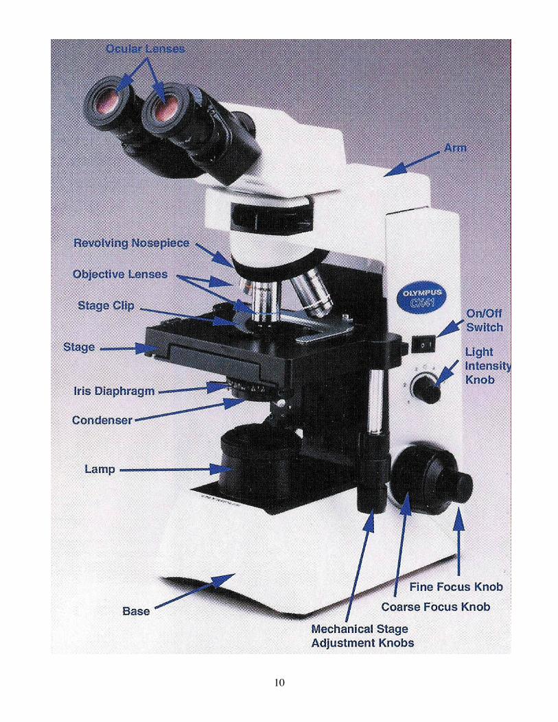
10

11
B. Additional Notes on Microscopy
PRE-FOCUSING LOCK: The Olympus Compound Microscope has an automatic pre-focusing lock located under the right coarse focusing knob. The lock prevents the accidental crushing of a slide against the objective by limiting the upward motion of the stage. The prefocusing lock is set by putting the lock in the upward position after coarse focusing at 10X. CONTRAST: Built into the condenser is an iris diaphragm, which regulates the amount of light passing through the condenser. To improve the contrast of specimens that are barely visible, the iris diaphragm should be partially closed. In achieving greater contrast, there is a loss of resolution so one must balance contrast and resolution for each specimen. OIL IMMERSION: Use of the oil immersion (100X) objective. Check the slide focus at 40X, and then rotate the nosepiece to the 4X position. Place a drop of Immersion oil on the Illuminated area of the slide. Rotate the 100X objective into place and focus with the tine focus knob only. Do not get oil on any other lenses. When finished clean the oil off the objective with clean lens paper by drawing the paper flat in one direction over the lens. Do not wipe the lens paper back and forth as it scratches the lens. DIAMETER OF THE FIELD AND MEASUREMENTS: Observe your microscope slide with the 4X, 10X and 40X objectives. As the magnification increases, the field of view decreases and the brightness of the field is reduced. Note also that the working distance between the slide and the objective decreases as the magnification is increased (this should make clear the reason you never focus on thick specimens with a 40X objective). You will calculate the diameter of the field for each of the objectives in the microscope you will use during the semester C. The Stereoscopic Dissecting Microscope The stereoscopic microscope differs from the compound microscope in that it has two (rather than one) objective lenses for each magnification. This type of microscope always has two oculars.
Essentially: the stereoscopic microscope is two microscopes in one. The great advantage of this instrument is that objects can be observed in three dimensions. Because the alignment of the two microscopes is critical, the resolution and magnification capabilities of a stereoscopic microscope are less than in a compound microscope. Stereoscopic microscopes are most often used for the microscopic dissection of specimens. The light source may come from above the specimen and be reflected back into the microscope or may come from underneath and be transmitted into the objectives. The stage may be clear glass or an opaque plate, white on one side and black on

12
the other. The choice of illumination source depends on the task to be performed and on whether the specimen is opaque or translucent. Some of the Olympus dissecting micro- scopes has a base with a light path selector switch that can be set for transmitted or reflected light or both. When using reflected light, adjust the mirror on the stand so light hits the center of the stage.
Magnification on this type of microscope usually range from 10X to 50X. The oculars can be
adjusted for individual eye spacing and for focus, as in the compound binocular micro- scope. There is only one focus control, a coarse adjustment knob.
Set your dissecting microscope up with reflected light. Place your hand on the stage and
observe a nail. Move your hand; how does image movement correspond to actual movement?
D. Electron Microscopy 1. SPECIMEN PREPARATION
Prior to placing a specimen into either the transmission electron microscope (TEM) or scanning electron microscope (SEM), samples must be prepared so that 1) the structures of the preserved sample accurately reflect the morphology of the living specimen and 2) the specimen can withstand the harsh internal environment (low vacuum, intense heat) of the electron microscope. As discussed below, the initial stages of specimen preparation are very similar for both TEM and SEM. However, the final stages differ greatly.
a. FIXATION: The purpose of fixation is to stabilize the molecular structure of the specimen during sample preparation. The fine structure of the specimen must be preserved with as little alteration as possible. Glutaraldehyde and osmium tetroxide are commonly used fixatives for electron microscopy. b. DEHYDRATION: Most embedding media (TEM) or transition fluids (SEM) are not soluble in water and consequently fixed specimens are dehydrated by passing them through a sequence of solutions, which are compatible with the embedding media. The two most commonly used dehydrating agents are ethanol and acetone. Following dehydration, the preparative techniques for TEM and SEM diverge.
TEM c. EMBEDDING: The final stage in the preparation of a biological specimen for thin sectioning is infiltration with a liquid embedding medium. The plastic medium polymerizes to produce a solid block. d. BLOCK TRIMMING: Before the specimen can be thin sectioned with an ultramicrotome, the plastic block containing the sample must be trimmed to a suitable size and shape with a razor blade. This operation is carried out under a dissecting microscope. e. THIN SECTIONING: Thin sections (less than 100 nm) are cut with an ultramicrotome using either broken glass or diamond knives. The sections are mounted on a copper wire mesh grid. f. STAINING: In the electron microscope image contrast is a function of electron scattering by the specimen. Since most biological materials are "transparent" to an electron beam, image contrast is enhanced by staining with heavy metals. Lead and uranium are two commonly used strains. SEM c. CRITICAL POINT DRYING: The specimen must be dry before placing it in the SEM. Ordinary air-drying may cause severe artifacts. The critical point dryer is a device used to eliminate all moisture from the sample without introducing artifacts. The dehydrating agent (e.g., ethanol) is exchanged for a transition fluid (generally liquid C02). The temperature and pressure of the transition fluid is gradually increased until, at a certain point (critical point), the liquid C02 immediately changes to a gas. The gaseous C02 is slowly vented away leaving a perfectly dry specimen.

13
d. SPECIMEN MOUNTING: Once dried, the specimen must be mounted on a STEM stub. These are always good electrical conductors and come in a variety of sizes to accommodate all specimens. e. SPUTTER COATING: Most biological samples are poor conductors. Striking the sample with a charged electron beam results in an accumulation of surface charges, which, in turn, causes severe imaging problems. This is solved by coating the specimen with a thin layer of conducting metal (gold or platinum). A sputter coater, which utilizes low vacuum and high electrical currents, is used in this operation. 2. THE ELECTRON MICROSCOPE a. VACUUM SYSTEM: Electrons have very poor penetrating power and are completely scattered
by air. For this reason electron microscopy is carried out in an evacuated column. The vacuum system consists of a mechanical and an oil diffusion pump. A vacuum of 10-4 tore must be maintained during operation of the microscope.
b. ILLUMINATION SYSTEM: This system contains the electron filament gun, which is the source
of electrons and the condenser lenses, which regulate the intensity of the beam and direct it onto the specimen.
c. LENSES: The lenses in an electron microscope are magnetic fields generated by an electrical
current passing through massive coils of wire. Lenses are focused by changing the strengths of their magnetic fields
d. IMAGE TRANSLATING SYSTEM: The electron image must be converted into a visible light image to be seen by the eye. This is done by projecting the electron image onto a fluorescent viewing screen. A1l electron microscopes are equipped with a viewing screen and either a camera or a videotape recorder.
e. TEM and SEM OPTICS: Although both the TEM and SEM utilize the above systems, the optics and, consequently, the information derived from the two types of instruments, differ greatly. As shown on the second page of this section, the TEM is simply a light microscope modified for use with an electron beam. Optically the light microscope and the TEM are very similar and both yield information concerning the internal structure of tissues and cells. However, the SEM is optically unique. The electron beam is focused to a very small diameter by condenser and objective lenses. This small diameter primary beam strikes the surface of a three dimensional sample (e.g., an insect) and a secondary beam of electrons is emitted from the surface of the sample. This secondary beam, the intensity of which is related to the surface contours of the specimen, strikes the image translating system and is eventually displayed on a CRT. Since the diameter of the primary beam is much smaller than the specimen, the beam must be continually scanned across the sample in order to obtain a complete image. Hence the name scanning electron microscope. SEM magnification varies from 30X to 75,000X with 40-angstrom resolution; the transmission electron micro- scope magnification is typically 1000X to 500,000X with 1.5-angstrom resolution.

14
EXERCISE 1.1: DETERMINATION OF FIELD DIAMETERS Compound Microscope:
Knowing the diameters of the viewing fields at the different magnifications possible on your compound microscope will help you determine the approximate sizes of the various organisms you will be studying in this course. These diameters are easily determined with the aid of a hemacytometer (see figure) according to the following procedure. 1. Turn the objective lens to the lowest magnification and focus the microscope on the reflective
portion of the hemacytometer. Etched into the glass of the hemacytometer is a grid of specific dimensions.
2. Using the hemacytometer as a ruler, measure the field diameter by aligning one end of the grid along the side the field. Determine the greatest distance (diameter) across the field to the nearest 0.05 mm (50µm).
3. Repeat for all magnifications and record the measurements.
Dissecting Microscope: Perform the same type of measurements with the dissecting microscope using a millimeter
ruler. 1. Turn the lens to the lowest magnification and focus the microscope on the millimeter ruler placed
flat on the stage. 2. Using the ruler, measure the field diameter by aligning one graduation marking along the side of the
field. Determine the greatest distance (diameter) across the field to the nearest 0.25mm (250µm). 3. Repeat for all magnifications and record the measurements.
EXERCISE 1.2: SIZE ESTIMATION The cells and organisms under study during this course differ widely in their sizes and features.
Indeed, some of the cells you will see, such as oocytes, are larger than many entire organisms. Because the units typically used for microscopic measurements (millimeters, micrometers) are probably not part of your everyday life experience, you should become familiar with these units and learn to estimate sizes in terms of them so as better to understand the relationships between cells, the organs they compose, and their relation to the entire organism.
Use the following technique to make a temporary wet mount for sample examination using a compound microscope. Smear a moderate amount of Vaseline on the back of one your hands, where it will be unlikely to rub off on your papers or slides. Lightly scrape the smear with one edge of a coverslip. Rotate the coverslip 180o and lightly scrape the smear again, to make a coverslip with Vaseline “ bridges”. Gently place the coverslip, Vaseline side down, on a microscope slide. Surface tension allows liquids samples to be loaded from the side.
You will be provided with different stages of the worm Caenorhabditis elegans having different sizes and shapes. 1. Place the specimens on slides and estimate their sizes. 2. Use the hemacytometers and rulers to determine he sizes more accurately. Don’t forget to include
the magnification of the eyepieces in your calculations!
EXERCISE 1.3: DETERMINATION OF VOLUMES
It is easy to get “stuck” thinking two dimensionally when using the microscope. When
considering differences in cell sizes as in the previous workshop, you probably think first of its diameter (2D) without consideration of the volume difference (3D).
Using the diameters you determined in exercise 2, determine the approximate volumes of the cells you measured. (Use the following relationships: V = 4/3 x π x r3 –the volume of a sphere; or V = π x r2 x h the volume of a cylinder).
What is the volume difference between cells differing in diameter by a factor of 10? 100?

15
OBSERVATIONS: E. Columnar Epithelial Tissue. Obtain a slide and use it as you become familiar with the microscope in section A. Identify the nuclei, basement membrane, connective tissue and secretory goblet cell. Columnar epithelial tissue lines the digestive tract. Other types of epithelial cells cover the outer body surfaces and line internal cavities and ducts. F. Squamous Epithelial Cells
Prepare a wet mount of epithelial cells by putting a drop of water or saliva on a clean micro- scope slide. Gently scrape the inside of your cheek with the flat end of a toothpick. Mix the cheek cells with water, then apply a coverslip by touching one edge to the liquid on the slide and gently lowering the coverslip with a dissecting needle to prevent trapping air bubbles. Examine your cells with the 10X and 40X objectives, reducing the light to improve contrast, if necessary, by closing the iris diaphragm. Squamous epithelial cells line the mouth and esophagus and are arranged in one or more layers. Locate the nucleus of the cell and note that the edges of some cells are folded over. Fine focus to observe these folds. Can you see the cell membrane? Compare this slide to the one on the Nomarski microscope demonstration.
To another slide of cheek cells, add one or two drops of methylene blue stain. After two minutes, blot off the excess stain and add a drop of water and a coverslip. What feature of epidermal cells stains most prominently with methylene blue? Using the procedure in Section B, estimate the diameter of five cells and five nuclei. Cell diameter = _______µm Nuclei diameter = ______µm Use the oil immersion objective to observe yellow-green granules in the cytoplasm. These are
mitochondria, which are the site of cellular energy production. Before proceeding further, remove the oil from the objective.
Repeat the above staining procedure using neutral red and a new slide of cheek cells Neutral red is a pH indicator (blue at low pH, red at neutral pH, and yellow-red at high pH) Is the nucleus

16
of an epidermal cell acid, neutral or basics
G. Protista The kingdom Protista consists of single celled eukaryotes. Some are photosynthetic, unicellular
algae, with chlorophyll, vacuoles and cell wails, which undoubtedly resemble the ancestors of the plant kingdom. Other protests, known as protozoans, Ingest their food and lack chloroplasts and cell wails; they are probably more like the ancestors of animals.
1. Phylum Sarcodina: This class of protozoan moves by extension and retraction of pseudopodia.
Amoeba occurs commonly among decaying vegetable matter in ponds and slow-flowing streams, but many specimens are marine and others live in the soil. Reproduction is asexual. Examples: Amoeba and Pelomyxa carolinesis (Chaos chaos). Obtain specimens from the jar on the front bench. Take care to avoid any vigorous movement of the culture since this will tend to cause the specimens to break apart. Place a small specimen of either Pelomyxa (a large Amoeba) or Amoeba. Apply a cover slip and observe, using lower power magnification. Note that the shape is constantly changing with the protrusion and retraction of pseudopodia (amoeboid movement) but the antenna and posterior ends are closely defined and permanent. Only the tips of the pseudopodia touch the surface, the main body of the animal is surrounded by water. Within the pseudopodia (which also serve for food capture), the protoplasm can be seen flowing in the direction of movement. Jar the slide, or touch the specimen with a fine needlepoint, and watch the rapid contraction reaction. What is the estimated size of Amoeba?______ µm
Amoeba
Euglena
2. Phylum Flagellate: these protista live in fresh and salt water, in moist soil, are often parasitic and
move by means of one or a few flagella. Example: Euglena gracilis is a highly motile, photo- synthetic unicellular organism. The flagellum at the anterior end is used for locomotion. Note the spiral swimming motion and the waves of contraction and expansion that pass along the length of the body.
H. Drosophila Larva Drosophila melanogaster develops from a fertilized egg to larva, pupa and adult (complete
metamorphosis). The larva's dark mouth hooks move continuously as it tunnels through the medium constantly eating. Larva has a high metabolism and an active system for regulating excretion and
17
osmoregulation. The Malphigian tubules of the larva function in the formation of urine, the transport of inorganic ions and reabsorbtion of metabolic products. Drosophila has two pairs of Malpighian tubules, one pair lying anterior to the abdomen and the other posterior. Each tubule pair unites to form a common ureter and enters the intestine between the mid and hindgut. Various mutants have colorless or red Malphigian tubules. Examine a Drosophila larva and find the Malphigian tubules using a dissecting microscope or under the 4 X lens of the compound microscope.
Larval diagram from: Ashburner, M. and T. Wright. 1978. The Genetics and Biology of Drosophila, Academic Press, New York. I. Cytoplasmic Streaming
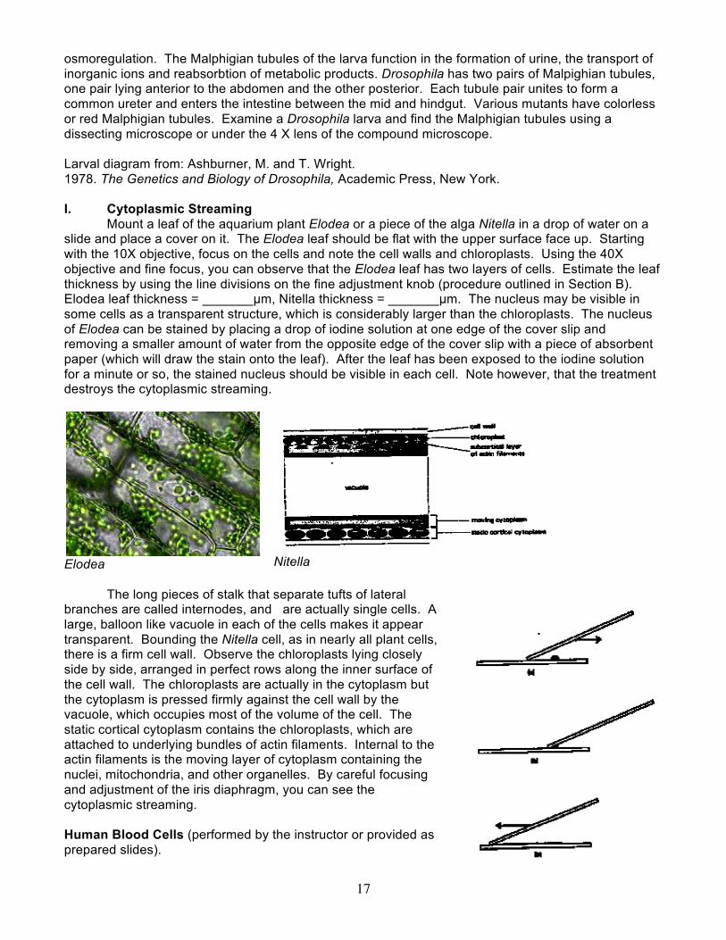
Mount a leaf of the aquarium plant Elodea or a piece of the alga Nitella in a drop of water on a slide and place a cover on it. The Elodea leaf should be flat with the upper surface face up. Starting with the 10X objective, focus on the cells and note the cell walls and chloroplasts. Using the 40X objective and fine focus, you can observe that the Elodea leaf has two layers of cells. Estimate the leaf thickness by using the line divisions on the fine adjustment knob (procedure outlined in Section B). Elodea leaf thickness = _______µm, Nitella thickness = _______µm. The nucleus may be visible in some cells as a transparent structure, which is considerably larger than the chloroplasts. The nucleus of Elodea can be stained by placing a drop of iodine solution at one edge of the cover slip and removing a smaller amount of water from the opposite edge of the cover slip with a piece of absorbent paper (which will draw the stain onto the leaf). After the leaf has been exposed to the iodine solution for a minute or so, the stained nucleus should be visible in each cell. Note however, that the treatment destroys the cytoplasmic streaming.
Elodea
Nitella
The long pieces of stalk that separate tufts of lateral
branches are called internodes, and are actually single cells. A large, balloon like vacuole in each of the cells makes it appear transparent. Bounding the Nitella cell, as in nearly all plant cells, there is a firm cell wall. Observe the chloroplasts lying closely side by side, arranged in perfect rows along the inner surface of the cell wall. The chloroplasts are actually in the cytoplasm but the cytoplasm is pressed firmly against the cell wall by the vacuole, which occupies most of the volume of the cell. The static cortical cytoplasm contains the chloroplasts, which are attached to underlying bundles of actin filaments. Internal to the actin filaments is the moving layer of cytoplasm containing the nuclei, mitochondria, and other organelles. By careful focusing and adjustment of the iris diaphragm, you can see the cytoplasmic streaming. Human Blood Cells (performed by the instructor or provided as prepared slides).

18
1. Clean the tip of your index finger with 70% alcohol. Puncture the fingertip once (with determination) using a sterile lancet. Squeeze out a drop of blood and touch it to the end of a glass slide.
2. Make several blood smears as illustrated. Allow the smears to dry completely. 3. Observe the unstained smear under the compound microscope. If an even distribution of cells
can be seen, the smear is appropriate for staining. Note what cell structures can be seen with the light microscope.
4. Stain the smear with Wright's stain as follows: place enough stain (5-9 drops) to cover the smear and allow it to stand for one minute. Add the same amount of distilled water to the stain and allow this stain dilution to stand for 2-3 minutes. Drain off the stain and rinse by dipping in a beaker of water. Allow the slide to dry completely.
If the stain has taken properly you should be able to observe the following under high power (40X). Most of the cells are red blood cells (erythrocytes when mature they contain no nuclei and they should look uniformly yellowish red. Blood platelets or thrombocytes look like clusters of dark specks, smaller than the red blood cells, but sharply distinguished and violet to purple in color Leukocytes are fewer in number, larger than erythrocytes and have either one nucleus and no cytoplasmic granules, or have lobed nuclei and cytoplasmic granules.
Typical cells of the blood.

19
Exercise 1.4: C. elegans worms: identify hermaphrodites and males; estimate and analyze lengths of worms from a mixed population
The purpose of this excersie is three-fold: 1) to practice the microscopy skills you learned during the previous week’s exercises, 2) to familiarize you with the worm Caenorhabditis elegans, and 3) to incorporate quantitative methods into the analysis of laboratory measurements. In addition to mice and fruit flies, the nematode C. elegans is one of the most widely-used multicellular animal model organisms. Most biological disciplines use C. elegans in their studies, although it was initially championed as an outstanding system for studying genetics and development. One of the most important reasons for the initial use of C. elegans in biological research is that it is a eutelic organism. This means that every individual has exactly the same number of cells in its body as every other individual, and the relative positions and identities of every cell are known. This enables maps of the cell lineages of this species to be produced (http://www.wormatlas.org/celllineages.html). The figure below depicts the life cycle of C. elegans; the web link below provides you with ample resources to learn more about this amazing organism.
Figure 1.4.1. From: http://www.wormatlas.org/ver1/handbook/anatomyintro/anatomyintro.htm
C. elegans individuals are one of two sexes: either male or hermaphrodite. In this species, the sex that would otherwise be called the female sex has gained the ability not only to produce eggs but also to produce sperm. These hermaphrodites (from Hermes + Aphrodite) internally self-fertilize to produce self-offspring. One hermaphrodite produces ~200–300 self offspring in its lifetime.

20
In nature, most C. elegans populations have very few males (perhaps ~ 1 in every 1,000 worms is a male). However, when males encounter hermaphrodites, the males can inseminate the hermaphrodites and produce some cross-offspring in addition to the hermaphrodite's own self-offspring. Nematode development initiates at fertilization. After the first several rounds of cell division, in which individual cells are visible, an individual continues to develop inside the cuticle until hatching, at which point the worm is in the first larval (L1) stage. Worms develop through three additional stages (L2, L3, and L4). In between each of these stages, the worm must shed its cuticle and molt to be able to grow. After the L4 stage, the final molt takes place, producing an adult. All of the individuals shown in the figure above are hermaphrodites, although the two sexes are indistinguishable until the late L4 stage. Adult hermaphrodites can be identified by the presence of fertilized eggs in the uterus (represented as bean-shaped objects on one side of the body, halfway between the head and the tail, in the figure above). Adult males are identified predominantly by a difference in the shape of the tail. Hermaphrodites have a long, slender, whip-like tail; males have a rather blunt, angular tail:
Figure 1.4.2. Differences in the anatomy of C. elegans hermaphrodites and b) males.
From Cline et al. (1996) Ann. Rev. Genet. Like in humans and fruit flies, sex determination has a genetic basis in C. elegans, summarized in the following table. All three species are normally diploid. XX XY XO XXY XXO
Human female male – Fruit fly female male –
C. elegans female (herm.)
– male female (herm.)

21
As you discuss the below questions in your groups and in class, fill in the blanks in the table above. What are the genetic differences between males and females of each species? What does the "O" in the table above represent? ___________________________________________ How would you tell what one genetic difference might be responsible for sex determination?
Figure 1.4.3. Micrographs of the apperance of C. elegans carrying the number of X chromosomes shown (and a normal diploid complement of autosomes). From Hodgkin et al. (1979) Genetics

22
Draw, in the appropriate ratio, the sex-chromosome haplotypes of gametes that typical C. elegans hermaphrodites and a typical C. elegans male would produce. The rarity of males in natural C. elegans populations (~1 in 1,000 individuals) essentially represents the frequency with which self-fertilizing hermaphrodites produce males. How does this differ from the frequency of males in humans and fruit flies (and most other species)? Draw the two gametes (and their sex-chromosome haplotypes) that would need to be produced by a hermaphrodite to produce a male? Can you think of a genetic mechanism that would produce the gamete haplotype necessary for a hermaphrodite to be able to generate a male offspring? What other haplotype would be produced at the same time? Given that ~99.9% of hermaphrodite gametes carry a normal sex chromosome haplotype, write the most likely genotypes of the individuals produced from the male-creating gamete and the gamete with the "other haplotype."

23
Make hypotheses for the following questions: 1) Do you expect that each developmental stage can be characterized by a discrete size or size range, as the above figure suggests? 2) Will adult males and hermaphrodites be distinguishable by size? If yes, which sex do you think will be larger? For this activity you will receive two samples of worms. 1) One plate will have a mutant C. elegans strain, him-5 (strain CB1467), which is a nondisjunction mutant that allows production of a high incidence of males (up to 20%) in the culture. 2) One microcentrifuge tube containing a liquid suspension of C. briggsae individuals (a species closely related, and essentially indistinguishable from C. elegans) in M9 buffer. You will also be provided with:
Vaseline, Plastic Pasteur pipettes, Microscope slides and coverslips, 0.5 M levamisole, and a dissecting and a compound microscope. Caenorhabditis nematodes are non-pathogenic. Levamisole is a toxic chemical: use appropriate personal protective equipment (including gloves and eye protection) when handling.
To do: 1) Place the agar plate containing CB1467 under the dissecting microscope and identify and observe the two sexes of C. elegans. Estimate and record the lengths (in µm) of ten adults of each sex, as well as all features you can observe that distinguish the two sexes. As each group completes its length estimates, we will record and plot all of the length data from the class on a common computer spreadsheet (provided by the instructor). 1) Expected results:
The posterior end of a hermaphrodite under
Nomarski optics (400X magnification) The posterior end of a male under Nomarski
optics (400X magnification) Figure 1.4.4. Micrographs of a hermaphrodite tail (left) and male tail (right).
24
2) Observe the different stages of C. briggsae under the compound microscope. As in the previous week (exercise 1.2), prepare a wet-mount slide using vaseline. To the tube containing the nematode suspension, add 0.5 M levamisole (nematode anaesthetic) to a final concentration of 50 mM. Invert the capped tube with the nematode suspension several times to mix; then pipette some of the suspension underneath the coverslip. a. Estimate and record the lengths (in µm) of at least thirty individuals (eggs, larvae, and adults). Take care to try to measure roughly equal numbers of individuals from each developmental stage. As each group completes its length estimates, we will record and plot all of the length data from the class on a common computer spreadsheet (provided by the instructor). b. While data are collected on the spreadsheet, return to your microscope slide. Some unique features must allow the different developmental stages to be distinguished, right?. If you have a computer in your lab group, access http://www.wormatlas.org (Hermaphrodite: Introduction: Section 3.2) to learn about whether obvious features can be used to tell the different stages apart. See if you can identify visual differences among the worms on your microscope slide that you might use to tell an L1 from L2, L2 from L3, and so on. Record your conclusions in your notebook. c. Discuss the following questions in your lab group; record your response in your notebook:
i) From the perspective of the cell, what causes any observable difference in size between members of the same species in nature? ii) What are the forces that would dictate which of these causes produces variation in organism size? iii) What characteristics does C. elegans have that make it a valuable model organism for developmental genetics? iv) What issues did you encounter during your experiments today, and what changes would you make to your experimental protocols in the future to improve the quality of data collected?
3) Clean up your lab station 4) Final Questions to discuss and to record in your notebook after the in-class data analysis on September 23:
a. Were your hypotheses rejected or not? Describe how statistical analyses of the data led to this conclusion. b. Do the data reflect the developmental stage size estimates listed on the worm development/lifecycle figure above? Do you think it would be valuable to update this figure in light of the data you collected today? Why or why not?