fallanderson/me_504st/me504st_session… · control systems," by richard c. dorf, addison...
TRANSCRIPT
ME
58
1/ E
CE
573 F
uzzy Logic C
ontrol Systems
Fall 2007
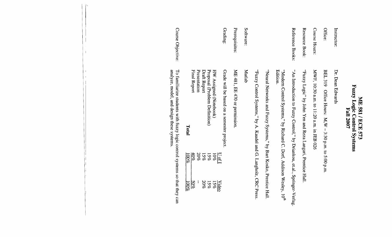
Instructor: D
r. Dean E
dwards
Office:
BE
L 319
Office H
ours: M
,W -
3:30 p.m. to 5:00 p.m
.
Course H
ours: M
WF
, 10:30 a.m. to 11:20 a.m
. in JEB
026
Resource B
ook: "F
uzzy Logic" by John Y
en and Reza L
angari, Prentice H
all.
Reference B
ooks: "A
n Introduction to Fuzzy C
ontrol," by Driankou, et.a1., S
pringer-Verlag.
"Modem
Control S
ystems," by R
ichard C. D
orf, Addison W
esley, 10th
Edition.
"Neural N
etworks and F
uzzy System
s," by Bart K
osko, Prentice H
all.
"Fuzzy C
ontrol System
s," by A. K
audel and G. L
angholz, CR
C P
ress.
Softw
are: M
atlab
Prerequisites:
ME
481, EE
470 or permission.
Grading:
Grade w
ill be based on a semester project.
U o
fl V
ideo H
W A
ssigned (Notebook)
10%
15%
Proposal (P
roblem D
efinition) 15%
15%
D
raft Report
15%
20%
Presentation
20%
Final Report
40%
50%
Total
100%
100%
Course O
bjective: T
o familiarize students w
ith fuzzy logic control systems so that they can
analyze, model, and design these system
s.
/

ME
58
1/ E
CE
573 F
uzzy Logic C
ontrol Systems
Course O
utline
Chapter 1
Introduction
Notes
Review
of C
lassical Control System
s
Chapter 2
Basic C
oncepts of F
uzzy Logic
Notes
Linear E
quivalent Fuzzy L
ogic Control S
ystem (L
EF
LC
)
Chapter 3
Fuzzy S
ets
Chapter 4
Fuzzy R
elations, Fuzzy G
raphs, and Fuzzy A
rithmetic
Chapter 5
Fuzzy If-T
hen Rules
Project P
roposal
Chapter 6
Fuzzy Im
plications and Approxim
ate Reasoning
Chapter 7
Fuzzy L
ogic and Probability T
heory
Chapter 8
Fuzzy L
ogic in Control E
ngineering
Draft P
roject Report
Chapter 14
Fuzzy M
odel Identification
Chapter 9
Hierarchical Intelligent C
ontrol
Chapter 10
Analytical Issues in F
uzzy Logic C
ontrol
Project P
resentations
Final P
roject Report

.,
-I


580 F
uzzy Control System
s
A F
UZ
ZY
LO
GIC
CO
NT
RO
LL
ER
F
OR
A R
IGID
DISK
DR
IVE
Shuichi Y
oshida Inform
ation Equipm
ent Research L
aboratory M
atsushita Electric Industrial C
o., Ltd.
Osaka, 571 Japan
1. IN
TR
OD
UC
TIO
N
With
the recent
trends tow
ard more
powerful
personal co
mp
uters
and w
orkstations has emerged a dem
and for magnetic rigid disk drives (R
DD
) and other peripheral storage devices w
hich are smaller in
size and provide greater storage capacities w
ith increased rates of data transfer to host com
puters. (See F
ig. 1.) T
he time for data transfer is determ
ined by the seek time required by the head
reading the data. This is the tim
e to move from
one data cylinder to the target cylinder. T
he seek time is lim
ited by the performance of the actuator m
oving the head as well as
by the control method.
This chapter show
s how to reduce seek tim
e, through a bang-bang controller em
ploying fuzzy logic together with a m
ethod for correcting for changes in actuator coil resistance and actuator force unevenness[l ,2,3].
Fig. 1
External V
iew of a R
igid Disk D
rive

9 C
OM
PA
RIS
ON
OF
FU
ZZ
Y
AN
D N
EU
RA
L
TR
UC
K B
AC
KE
R-U
PP
ER
C
ON
TR
OL
SY
ST
EM
S
Seon~~Gol'rKon
g and Bart K
osko
FU
ZZ
Y A
ND
NE
UR
AL
CO
NT
RO
L S
YS
TE
MS
In this chapter we develop fuzzy and neural system
s to back up a simulated
truck, and truck-and-trailer, to a loading dock in a planar parking lot. W
e use differential com
petitive learning and the product-space clustering technique, discussed in C
hap
ter 8, to adaptively generate fuzzy-associative-mem
ory (FA
M) rules from
training data taken from
the fuzzy and neural simulations.
We developed the neural truck system
s on the design recently proposed by N
guyen and Widrow
[1989]. W
e trained the neural truck systems w
ith the backpropagation learning algorithm
, discussed in Chapter 5.
In principle product-space clustering can convert any neural black-box system
into a representative set of FA
M
rules.
339
340 C
OM
PA
RIS
ON
OF
FU
ZZ
Y A
ND
NE
UR
AL C
ON
TR
OL S
YS
TE
MS
C
HA
P. 9
loading dock (xf · Yf)
I
rear
front
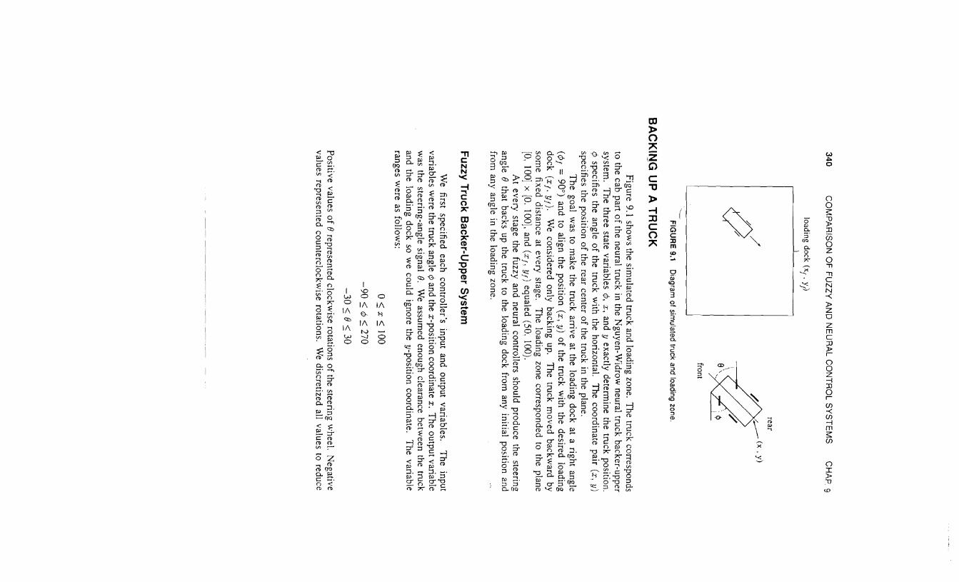
FIG
UR
E 9.1
Diagram
of simulated truck and loading zone.
BA
CK
ING
UP
A T
RU
CK
Figure 9.1 show
s the simulated truck and loading zone. T
he truck corresponds to the cab part o
f the neural truck in the Nguyen-W
idrow neural truck backer-upper
system.
The three state variables ¢
, x, and y exactly determine the truck position.
¢ specifies the angle o
f the truck with the horizontal.
The coordinate pair (x, y)
specifies the position of the rear center o
f the truck in the plane. T
he goal w
as to make the truck arrive at the loading dock at a right angle
(¢f =
90°) and to align the position (x, y)
of the truck w
ith the desired loading d
ock
(x
f. Yf).
We considered only backing up.
The truck m
oved backward by
some fixed distance at every stage.
The loading zone corresponded to the plane
[0. 100] x [0.
100], and (Xf.
Yf) equaled (50, 100).
At every stage the fuzzy and neural controllers should produce the steering
angle e that backs up the truck to the loading dock from any initial position and
from any angle in the loading zone.
Fu
zzy Tru
ck Backer-U
pp
er System
We
first specified each controller's
input and output variables.
The
input variables w
ere the truck angle ¢ and the x-position coordinate x. Th
e output variable w
as the steering-angle signal e. W
e assumed enough clearance betw
een the truck and the loading dock so w
e could ignore the y-position coordinate. T
he variable ranges w
ere as follows:
0~x~100
-90
~ ¢
~ 270
-30
:; e:; 30 P
ositive values of e
represented clockwise rotations o
f the steering wheel.
Negative
values represented counterclockwise rotations.
We discretized all values to reduce
BA
CK
ING
UP
A T
RU
CK
(a)
(b) (c)
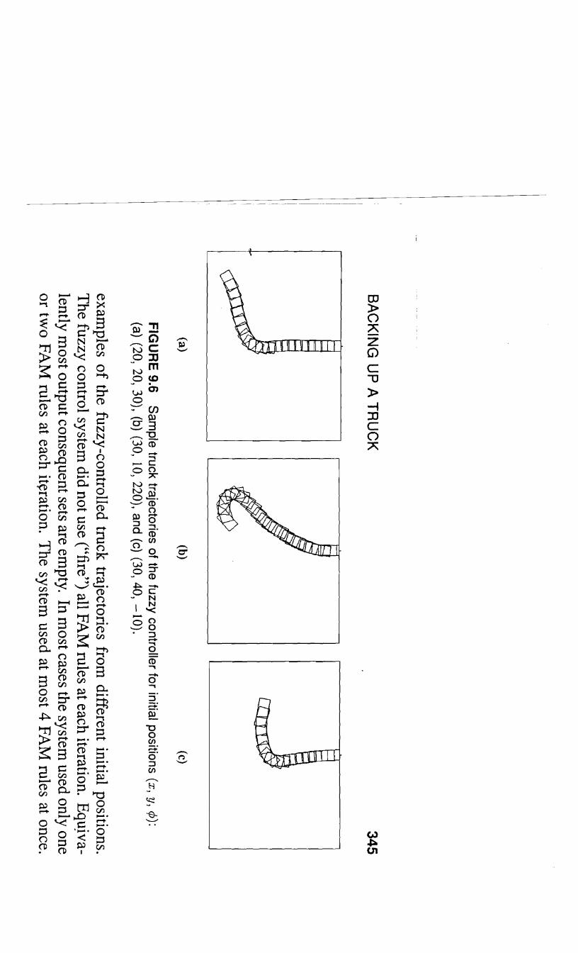
FIG
UR
E 9.6
Sam
ple truck trajectories of the fuzzy controller for initial positions (x, y, C/»: (a) (20, 20, 30), (b) (30, 10, 220), and (c) (30, 40, -1
0).
examples o
f the fuzzy-controlled truck trajectories from different initial positions.
The fuzzy control system
did not use ("fire") all FAM
rules at each iteration. Equjva
lently most output consequent sets are em
pty. In most cases the system
used only one or tw
o FA
M rules at each it~ration. T
he system used at m
ost 4 FAM
rules at once.
345
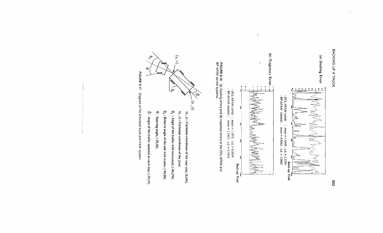
353 B
AC
KIN
G U
P A
TR
UC
K
(a) Docking E
rror
Back-up T
rial -
DC
L-A
FAM
(solid) m
ean = 1.4449.
s.d. = 2.2594
-B
P-AFA
M
(dashed): m
ean = 6.6863.
s.d. = 1.0665
(b) Trajector}' E
rror, 5
~
:::~W\i~ (' A, ~!j. j~ hi!b\tl\(: ,::;l t : :'L'~"'1\J![V~W\lilVr 'tJ v
vw~
..
II..
Be
1••
Back-up T
rial
-D
CL
-AFA
M (solid)
mean =
1.1075. s.d. =
0.0839 -
BP-A
FAM
(dashed): m
ean = 1.1453.
s.d. = 0.1016
FIG
UR
E 9.16
(a) Docking errors and (b) trajectory errors of the D
CL-A
FA
M and
BP
-AF
AM
control systems.
(x, y) (x
, y) : Cartesian
coo
rdin
ate of the rear end, [0,100).
(u, v) : C
artesian coordinate o
f the joint.
<Pt : A
ngle of the trailer w
ith horizontal, [-90,270).
<Pc: Relative angle o
f the cab with trailer, [-90,90j.
e:S
teering angle, [-30,30).
~ : A
ngle of the trailer u
pd
ated at each step, [-30,30].
FIG
UR
E 9.17
Diagram
of the simulated truck-and-trailer system
.

11
CO
MP
AR
ISO
N O
F F
UZ
ZY
A
ND
KA
LM
AN
-FIL
TE
R
TA
RG
ET
-TR
AC
KIN
G
··CO
NTR
OL S
YS
TE
MS
P
eter J. Pacjni and B
art Kosko
In Chapter 9, w
e compared fuzzy and neural system
s for the comparatively sim
ple control problem
of backing up a truck to a fixed loading dock in an em
pty parking lot.
In this chapter, we com
pare a fuzzy system w
ith a Kalm
an filter system for real
time target tracking. T
he Kalm
an filter is an optimal stochastic linear adaptive filter,
or controller, and requires an explicit m
athematical m
odel of how
control outputs depend on control inputs. In this sense the K
alman filter is a paragon o
f math-m
odel co
ntro
llers-and
a challenging benchmark for alternative control system
s.
FU
ZZ
Y A
ND
MA
TH
-MO
DE
L CO
NT
RO
LLER
S
Fuzzy controllers differ from
classical m
ath-model controllers.
Fuzzy con
trollers do not require a mathem
atical model o
f how control outputs functionally
depend on control inputs. F
uzzy controllers also differ in the type of uncertainty they
represent and how they represent it.
The fuzzy approach represents am
biguous or
fuzzy-system behavior as partial im
plications or approximate "rules o
f thu
mb
"-as
fuzzy associations (.-1.,. Bi ).
379

-I I
I-