fan efficiency metrics eedal 2017-9-14 fei eedal 2017... · •fei would be calculated using rating...
TRANSCRIPT
©2017 Air Movement and Control Association. All Rights Reserved.
Michael IvanovichSenior Director, Industry RelationsAir Movement and Control Association International, Inc.
Fan Efficiency Metrics

©2016 Air Movement and Control Association. All Rights Reserved.
2
• Introduction to AMCA•Why Obsolete the Current Metric (FEG)?• Introduction of the Fan Energy Index•Questions
Presentation Outline

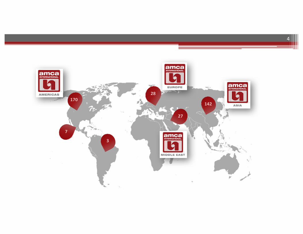
•Air Movement and Control Association Int.•Not-for-profit manufacturers association
established in 1917•More than 370 member companies worldwide•Mission is to promote the health, growth and
integrity of the air movement and control industry
3
Introduction to AMCA
4
28
7
27
170142
3

5
•Test Standards§ANSI Accredited§ ISO Member•Application Guides•White Papers•Videos•Magazine•Social Media
Content Development

•Meetings• Conferences• Engineering Seminars•Workshops
6
AMCA Educational Programs
2017 AMCA Spring MeetingsFebruary 27 & 28, 2017
Scottsdale, AZ
Find Your Way Out West.
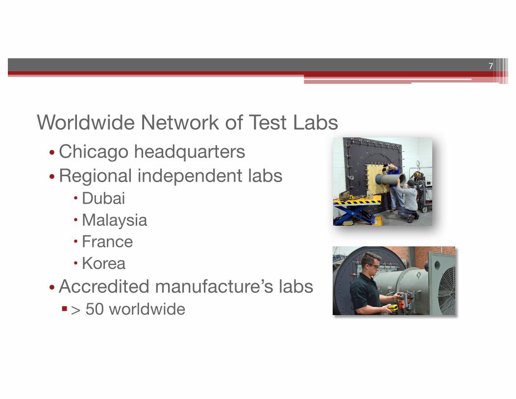
•Chicago headquarters•Regional independent labs
�Dubai�Malaysia� France�Korea
•Accredited manufacture’s labs§> 50 worldwide
7
Worldwide Network of Test Labs
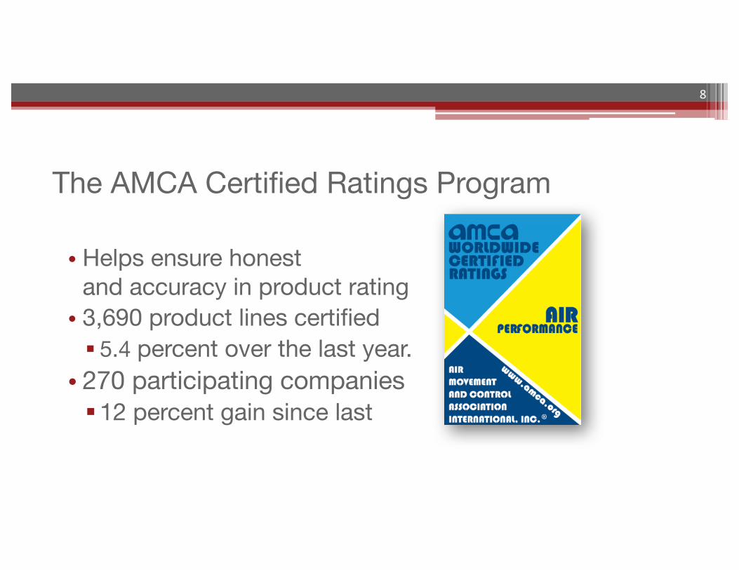
• Helps ensure honest and accuracy in product rating• 3,690 product lines certified§ 5.4 percent over the last year. • 270 participating companies§12 percent gain since last
8
The AMCA Certified Ratings Program

©2016 Air Movement and Control Association. All Rights Reserved.
9
Why Obsolete the Current Metric (FEG)?

“Elements” of Fan Power
ElectricalPowerIn
MotorLoss(10%)
DriveLoss(3%-10%)
BearingLoss(3%)
AerodynamicLoss(10%to20%)
FanPowerOut
FanPower(attheshaft)
10
OverallFanPower(wiretoair)

©2016 Air Movement and Control Association. All Rights Reserved.
11
Fan Efficiency Grade
0 5 10 15 20 25 30 35 40
Peak
Tot
al E
ffici
ency
, pTE
(%)
90
80
70
60
50
40
30
20
Impeller Diameter (in)
FEG 85
FEG 80
FEG 75
FEG 71
FEG 67FEG 63FEG 60FEG 56FEG 53FEG 50
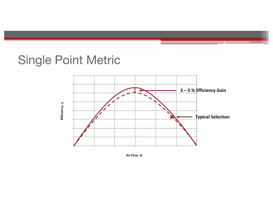
Single Point Metric
Air Flow, Q
Effic
ienc
y, η
4
3– 5%EfficiencyGain
TypicalSelection
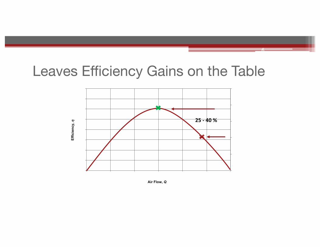
Leaves Efficiency Gains on the Table
Air Flow, Q
Effic
ienc
y, η
6
25- 40%
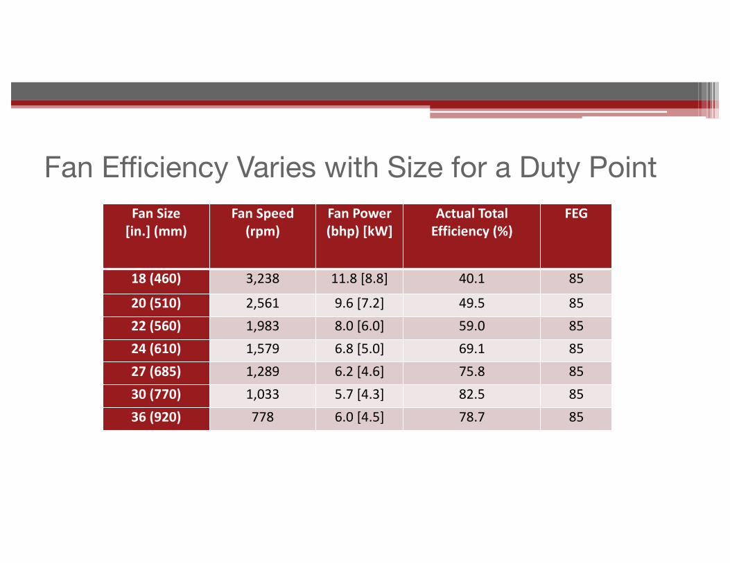
Fan Efficiency Varies with Size for a Duty PointFanSize[in.](mm)
FanSpeed(rpm)
FanPower(bhp)[kW]
ActualTotalEfficiency(%)
FEG
18(460) 3,238 11.8[8.8] 40.1 85
20(510) 2,561 9.6[7.2] 49.5 8522(560) 1,983 8.0[6.0] 59.0 8524(610) 1,579 6.8[5.0] 69.1 8527(685) 1,289 6.2[4.6] 75.8 8530(770) 1,033 5.7[4.3] 82.5 8536(920) 778 6.0[4.5] 78.7 85
©2016 Air Movement and Control Association. All Rights Reserved.
15
• The regulation of electrical input power• The use of fan static pressure for non-ducted fans• The elimination of categories to allow product
substitution• DOE could not regulate fan application, but they COULD
regulate how fan data is presented to the public
Finally, we also needed to address:

• Typical regulations are based on increasing “peak efficiency” by eliminating products that do meet a baseline “peak efficiency”• Fan efficiency is highly sensitive to actual operating conditions• Peak fan efficiency for a given model varies little across
diameters§ FEG used in ASHRAE 90.1 has this characteristic§ Peak fan efficiency for a given model varies slightly with fan speed.
Regulatory Dilemma

• Typical practice is to select smaller-diameter fans for lowest first cost• Result is smaller, less-efficient fans that meet peak-efficiency
requirements§ 90.1 had provision for selecting fans within 10 percentage points of
peak total efficiency§ Greatly complicates application and enforcement
Regulatory Dilemma
©2016 Air Movement and Control Association. All Rights Reserved.
18
Introduction of the Fan Energy Index

• Selection bubbles are regions of a fan curve that are compliant• Designers must size and select fans so that the nominal design
point falls within the bubble• Manufacturers software will only show compliant selections for
given operating conditions• The direct result is that few fan are models eliminated from
market• Some shifting from less-efficient types to more-efficient types• Emphasis is on proper sizing and selection
Fan Energy Index Establishes “Selection Bubbles”
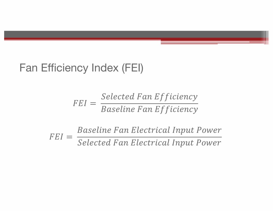
Fan Efficiency Index (FEI)
𝐹𝐸𝐼 = 𝑆𝑒𝑙𝑒𝑐𝑡𝑒𝑑𝐹𝑎𝑛𝐸𝑓𝑓𝑖𝑐𝑖𝑒𝑛𝑐𝑦𝐵𝑎𝑠𝑒𝑙𝑖𝑛𝑒𝐹𝑎𝑛𝐸𝑓𝑓𝑖𝑐𝑖𝑒𝑛𝑐𝑦
𝐹𝐸𝐼 = 𝐵𝑎𝑠𝑒𝑙𝑖𝑛𝑒𝐹𝑎𝑛𝐸𝑙𝑒𝑐𝑡𝑟𝑖𝑐𝑎𝑙𝐼𝑛𝑝𝑢𝑡𝑃𝑜𝑤𝑒𝑟𝑆𝑒𝑙𝑒𝑐𝑡𝑒𝑑𝐹𝑎𝑛𝐸𝑙𝑒𝑐𝑡𝑟𝑖𝑐𝑎𝑙𝐼𝑛𝑝𝑢𝑡𝑃𝑜𝑤𝑒𝑟
©2016 Air Movement and Control Association. All Rights Reserved.
21
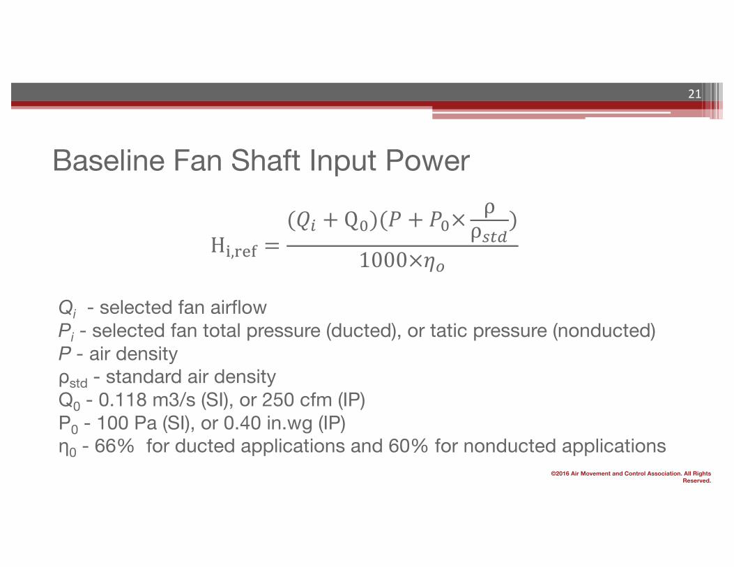
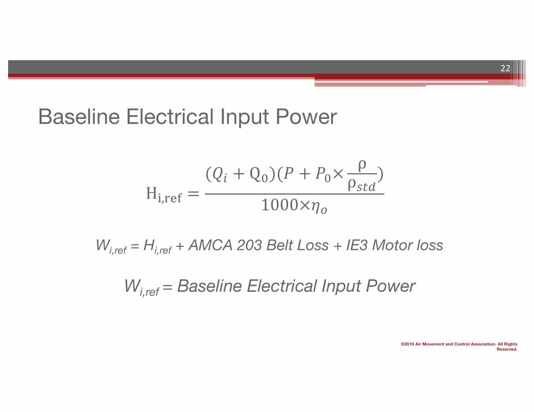
H:,<=> =(𝑄A + QD)(𝑃 + 𝑃D×
ρρHIJ
)
1000×𝜂N
Qi - selected fan airflowPi - selected fan total pressure (ducted), or tatic pressure (nonducted)Ρ - air densityρstd - standard air densityQ0 - 0.118 m3/s (SI), or 250 cfm (IP) P0 - 100 Pa (SI), or 0.40 in.wg (IP)η0 - 66% for ducted applications and 60% for nonducted applications
Baseline Fan Shaft Input Power
©2016 Air Movement and Control Association. All Rights Reserved.
22
H:,<=> =(𝑄A + QD)(𝑃 + 𝑃D×
ρρHIJ
)
1000×𝜂N
Wi,ref = Hi,ref + AMCA 203 Belt Loss + IE3 Motor loss
Wi,ref = Baseline Electrical Input Power
Baseline Electrical Input Power
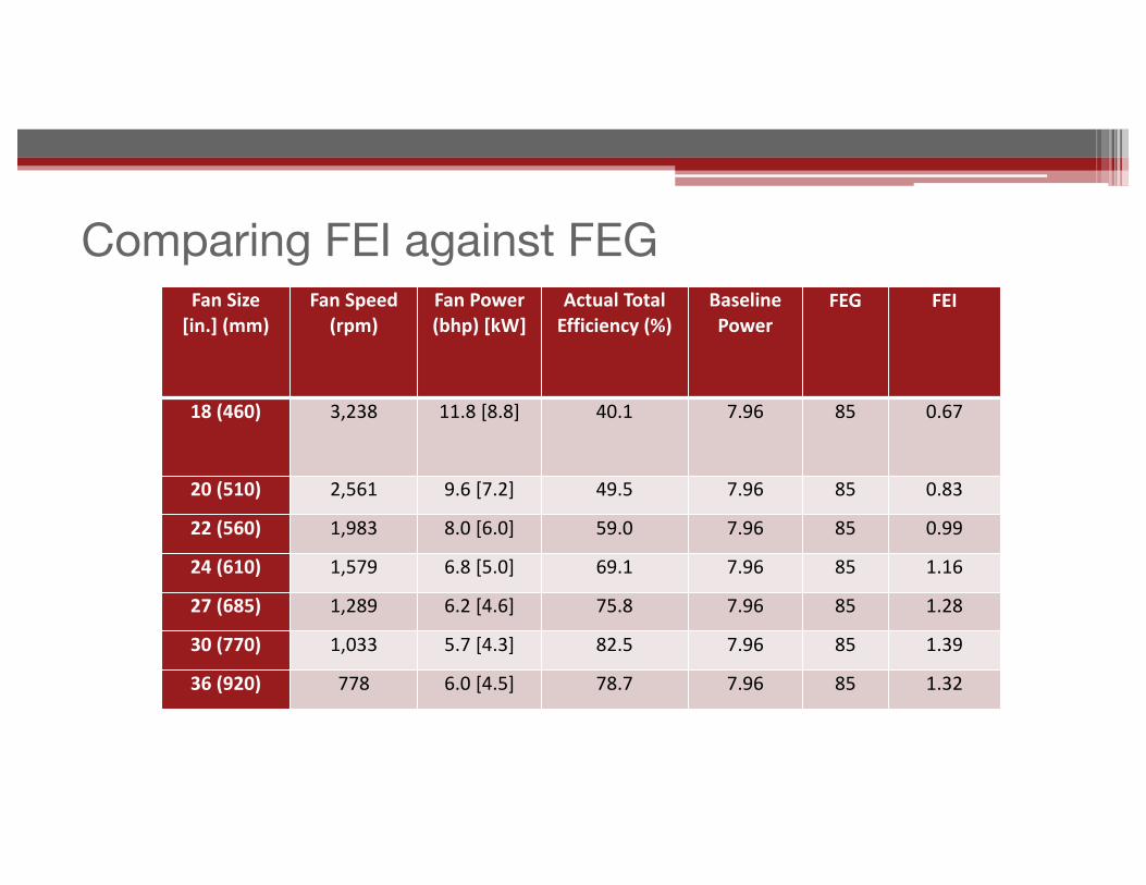
Comparing FEI against FEGFanSize[in.](mm)
FanSpeed(rpm)
FanPower(bhp)[kW]
ActualTotalEfficiency(%)
BaselinePower
FEG FEI
18(460) 3,238 11.8[8.8] 40.1 7.96 85 0.67
20(510) 2,561 9.6[7.2] 49.5 7.96 85 0.83
22(560) 1,983 8.0[6.0] 59.0 7.96 85 0.99
24(610) 1,579 6.8[5.0] 69.1 7.96 85 1.16
27(685) 1,289 6.2[4.6] 75.8 7.96 85 1.28
30(770) 1,033 5.7[4.3] 82.5 7.96 85 1.39
36(920) 778 6.0[4.5] 78.7 7.96 85 1.32

FanSize(in.)[mm] FanSpeed(rpm)
SpeedReductionfromSmallestDiameter
FanPower(bhp)
PowerReductionfromSmallestDiameter
ActualTotalEfficiency
EfficiencyimprovementOverSmallestDiameter
BaselinePower(bhp) FEI
FEIImprovementoverSmallest
Diamter
18 [460] 3238 11.8 40.10% 7.96 0.67
20 [510] 2561 79% 9.56 81% 49.50% 23% 7.96 0.83 24%
22 [560] 1983 61% 8.02 68% 59.00% 47% 7.96 0.99 48%
24 [610] 1579 49% 6.84 58% 69.10% 72% 7.96 1.16 73%
27 [685] 1289 40% 6.24 53% 75.80% 89% 7.96 1.28 91%
30 [770] 1033 32% 5.73 49% 82.50% 106% 7.96 1.39 107%
33 [840] 887 27% 5.67 48% 83.40% 108% 7.96 1.4 109%
36 [920] 778 24% 6.01 51% 78.70% 96% 7.96 1.32 97%
More Comparisons

How Will FEI Be Used?
FEI = 1.10 means 10% energy savings over baseline
Body FEI Requirement (forecast – not certain)
U.S. Federal or California Regulation FEI ≥ 1.0 at Design Point
ASHRAE 90.1 FEI ≥ 1.0 at Design Point
ASHRAE 189.1 FEI ≥ 1.10 at Design Point
Rebates FEI = Savings over Baseline
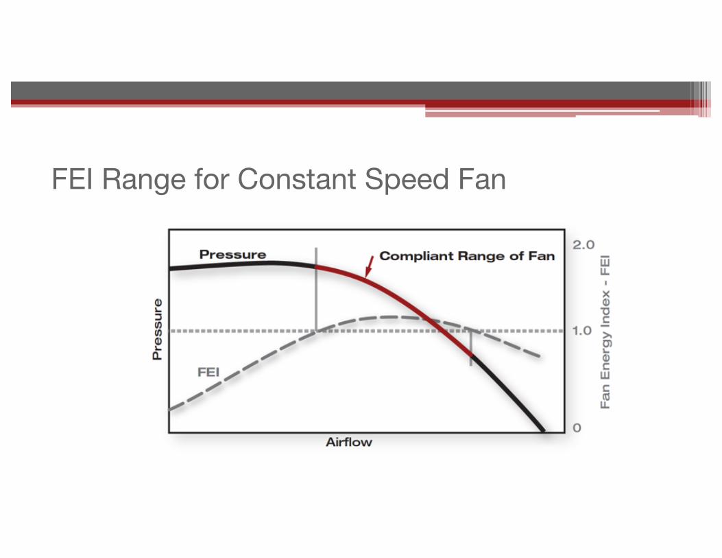
FEI Range for Constant Speed Fan

FEI Range for Centrifugal with Speed Control
EFFICIENTFAN INEFFICIENTFAN
©2016 Air Movement and Control Association. All Rights Reserved.
28
• AMCA Standard 208 in ballot phase per ANSI process• AMCA 208 will be integrated into ISO 12759• Default losses for drive components based on AMCA 207
(draft ISO 12750)• FEI would be calculated using rating data taken during
AMCA 210 or ISO 5801 tests• U.S. DOE regulation stalled, but would be based on FEI• California started regulation picking up where DOE left off• ASHRAE 90.1 replacing FEG with FEI• U.S. efficiency rebates will be based on FEI
Status

©2016 Air Movement and Control Association. All Rights Reserved.
29
• AMCA International: www.amca.org• AMCA White Papers: www.amca.org/whitepapers• AMCA Standards Bookstore: www.amca.org/store
Resources
Thank You Very Much… and…Questions?