fanless cooling for - cse servicesranger.uta.edu/~walker/cse...
TRANSCRIPT
321057
Fanless Cooling for Embedded Applications
January 2009
White Paper Chun Howe Sim
Thermal Mechanical Application Engineer
Jason Loh
Thermal Mechanical Application Engineer
Intel Corporation

Fan-less Cooling for Embedded Application
2 321057
Executive Summary Embedded market opportunities for Intel® architecture components exist
in Point-Of-Sale Terminals, Digital Signage, and Digital Security
Surveillance market segments to name a few. When selecting Intel®
architecture, several key metrics customers pay attention to include
performance/watt, Thermal Design Power (TDP), total cost of ownership,
and reliability. The Embedded Computing Group (ECG) offers scalability
with Intel® architecture products ranging from full power (35W and up) to
low power (10W~15W) to ultra low power (~5W) Intel® architecture
system solutions to address these market segments and requirements.
The objective of this white paper is to provide system designers a
reference fanless cooling solution for a Point-Of-Sale application.
Why a fanless solution? Higher reliability, lower cost, and lower power
applications are among the primary selection criteria when considering
whether to design a system with or without a fan. Other considerations
include smaller form factor requirements, acoustic constraints, and
specific working environments. The majority of “off the shelf” thermal
solutions are not suitable for adoption in fanless applications; and often
experience overheating in the system and/or an over designed thermal
solution.
This paper will provide emphasis on component level natural convection
heatsink characterization and optimization followed by a first level system
approximation utilizing a CFD simulation.

Fan-less Cooling for Embedded Application
321057 3
Contents Executive Summary ................................................................................................2
Contents ...............................................................................................................3
Background ...........................................................................................................4
Thermal Solution Design (Analytic)............................................................................4 Natural Convection Theory .....................................................................4 Volumetric Expansivity...........................................................................5 Optimized Plate Fins Spacing ..................................................................6 Bare Die Type Package Thermal Solution Stackup......................................7 Thermal Performance Characterization for Bare Die....................................8
Thermal Solution Design (Numerical).......................................................................11 Component Level CFD..........................................................................11 System Level CFD ...............................................................................15
Conclusion ...........................................................................................................18
Reference Documents............................................................................................20

Fan-less Cooling for Embedded Application
4 321057
Background Intel has been in the embedded business for greater than 30 years and apart from performance per watt, most of the time, customers are primarily concerned about Thermal Design Power (TDP). In embedded markets, most customers are looking for small form factors, low cost, high reliability and low power. The Embedded Communication Group (ECG) within Intel has addressed the specific needs for different embedded market segments, offering a wide range of products ranging from performance to ultra low power to system-on-a-chip (SoC) solutions. Ultra low power solutions are often considered by many customers in fan-less applications: examples include Point-of-Sale terminals, digital signage, in-vehicle infotainment and digital security surveillance.
For many reasons fanless applications are getting more and more attention; simple direct adopting of market available heatsinks is no longer feasible. A clear understanding on natural convection heat transfer and how this theory can be applied to component level and system level thermal solution design is crucial. This paper will provide as a reference for designing a fanless heatsink solution for an Ultra Low Voltage (ULV) Intel® architecture processor.
This paper is divided into three main sections, starting with an analytical hand calculation to approximate an optimum fin spacing of a heatsink for a natural convection heat transfer and the use of industry standards in component level numerical simulation; next is applied design on experiment (DOE) to determine heatsink geometry design inclusive of fin spacing, heatsink base thickness and fin thickness. The final section is system level Computational Fluid Dynamics (CFD) analysis where a Printed Circuit Board (PCB) form factor, component placement, and chassis vent holes are taken into design consideration. The example depicted in this section is a Point-of-Sale terminal with dual independent displays.
Thermal Solution Design (Analytic)
Natural Convection Theory
Natural convection, also known both as free convection and fanless (a more commonly marketing term), is a sub-classification of convection heat transfer. Unlike forced convection, natural convection airflow is induced by buoyancy forces; a result of density differences caused by temperature variation in the fluid. (In the semiconductor industry, most of the time the fluid is air unless otherwise specified) For additional information, please refer to References [1] and [2], Reference Documents.
Fan-less Cooling for Embedded Application
321057 5
Apart from convection, another major heat dissipating factor in natural convection is radiation heat transfer. Analytical hand calculation on heatsink radiation is comprehensive, complex and will not be discussed in this paper; for further reading please, refer to Chapter 12 in Reference [1], Reference Documents. Radiation is addressed in CFD simulation section; all model simulated in Flotherm * will have radiation turned on.
In natural convection, where the velocity of moving air is unknown, there is no single velocity analogous to the free stream velocity that can be used to characterize the flow. Thus, you cannot use the Reynolds number in the computation. Instead, use the Grashof number to correlate natural convection flows. The Grashof number is defined as follows:
Equation 1 Pr
)(2
32 RaLTTgGr fS =
−=
μβρ
Where:
g = acceleration of gravity (m/s2)
β = volume expansivity (1/K)
ρ = density of fluid (kg/m3)
Ts = surface temperature (K)
Tf = fluid temperature (K)
L = characteristic length (m)
μ = viscosity of fluid (Ns/m2)
Ra = Rayleigh number
Pr = Prandtl number
Grashof number is a dimensionless number in fluid dynamics and heat transfer which approximates the ratio of the buoyancy to viscous force acting on a fluid. At higher Gr the boundary layer is turbulent while at lower Gr the boundary layer is laminar.
Volumetric Expansivity
Volumetric expansivity of a fluid provides a measure of the amount the density changes in response to a change in temperature at constant
Fan-less Cooling for Embedded Application
6 321057
pressure. In most cases, a lab experiment is required to compute the value. For this discussion, the Ideal Gas Law to compute β for air will be applied.
Equation 2
where Tf in Ideal Gas Law must be expressed on an absolute scale (Kelvin or Rankine). For more information please see Reference [2], Reference Documents.
Substituting Equation 2 into Equation 1 becomes
Equation 3
Converting Grashof number to Rayleigh number Equation 3 becomes
Equation 4
Rayleigh number for a fluid is a dimensionless number associated with buoyancy driven flow (also known as natural convection). It is viewed as the ratio of buoyancy force and thermal momentum diffusivities.
Optimized Plate Fins Spacing
Optimizing thermal performance of a natural convection thermal solution involves a much broader design consideration; determining the correct fin spacing is just a part of the process. As mentioned in the earlier section, natural convection occurs mainly due to buoyancy force. Optimal fin spacing is needed to allow airflow between fins to circulate as freely as possible. In a steady state condition analysis, one could assume that thermal solution fins are close to isothermal and optimal fin spacing can be defined with a known thermal solution volume (WxDxH) as
Equation 5
Where:
S = optimum fin spacing
L = fin length parallel to airflow direction
Ra = Rayleigh number
Knowing Ra from Equation 4, we can now substitute it into Equation 5
41)(
714.2Ra
LS =
2
32 Pr)(Pr
μρ
f
fS
TLTTg
GrRa−
==
2
32 )(μ
ρ
f
fS
TLTTg
Gr−
=
fT1
=β
Fan-less Cooling for Embedded Application
321057 7
Equation 6
For more information on optimum fin spacing please see Reference [7], Reference Documents.
Bare Die Type Package Thermal Solution Stackup
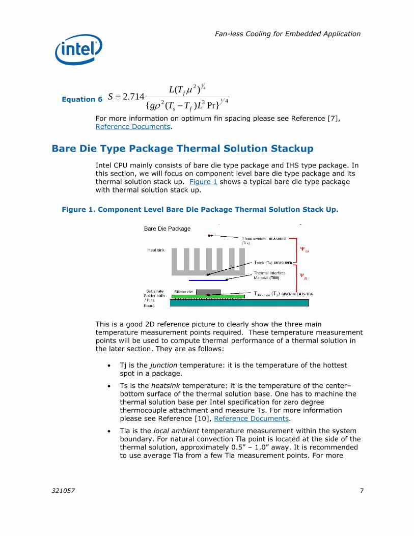
Intel CPU mainly consists of bare die type package and IHS type package. In this section, we will focus on component level bare die type package and its thermal solution stack up. Figure 1 shows a typical bare die type package with thermal solution stack up.
Figure 1. Component Level Bare Die Package Thermal Solution Stack Up.
This is a good 2D reference picture to clearly show the three main temperature measurement points required. These temperature measurement points will be used to compute thermal performance of a thermal solution in the later section. They are as follows:
• Tj is the junction temperature: it is the temperature of the hottest spot in a package.
• Ts is the heatsink temperature: it is the temperature of the center–bottom surface of the thermal solution base. One has to machine the thermal solution base per Intel specification for zero degree thermocouple attachment and measure Ts. For more information please see Reference [10], Reference Documents.
• Tla is the local ambient temperature measurement within the system boundary. For natural convection Tla point is located at the side of the thermal solution, approximately 0.5” – 1.0” away. It is recommended to use average Tla from a few Tla measurement points. For more
432
2
1
41
Pr})({
)(714.2
LTTg
TLS
fs
f
−=
ρ
μ

Fan-less Cooling for Embedded Application
8 321057
details on exact measurement and location point please see References [4] and [5] in Reference Documents.
Thermal Performance Characterization for Bare Die
Thermal performance and thermal resistance are often confused and loosely used in the industry. Thermal performance (Ψ) is an industrial standard to characterize thermal solution cooling performance. The thermal performance requirement is determined by calculating the junction-to-ambient thermal resistance ΨJA. This is a basic thermal engineering parameter that is used to evaluate and compare different thermal solutions. Thermal resistance from junction to ambient is a sum of thermal resistance of silicon die, TIM, and heatsink as shown in Equation 7.
Equation 7 SACSJCJA ψψψψ ++=
ΨJC value can be obtained from the chipset/processor manufacturer. Most of the TIM manufacturers will provide users the thermal resistance value RTIM which can be used to compute ΨCS. (Refer to Equation 8)
Equation 8 )(PDFRTIMCS =ψ
PDF is Intel’s power density factor and is available upon request from thermal mechanical application engineer. If off-the-shelf thermal solution is used, then ΨSA is available through heatsink vendors. For custom design, CFD and/or lab experiment determines ΨSA value. For more information on ΨJA and ΨSA calculations please see Reference [4], Reference Documents.
Thermal resistance (θ) on the other hand is the characterization of a package’s temperature rise per watt. This value dictates what thermal solution to use or design. To calculate thermal resistance θJA of the CPU, you have to define the local ambient temperature and then obtain the junction temperature and TDP from Intel TDG (see Equation 9).
Equation 9
Figure 2 is an example of a range of local ambient temperature vs. thermal resistance plot. As shown in the graph, the blue line distinguishes acceptable thermal solution performance for cooling; a thermal solution of performance ΨJA used must be within the darker grey area for effective cooling.
TDPTT AJ
JA−
=θ

Fan-less Cooling for Embedded Application
321057 9
Figure 2. Thermal Resistance of a CPU With Respect to a Range of Local Ambient Temperature
In summary, we want to design a thermal solution with ΨJA ≤ θJA at specified local ambient temperature range.
Example of an Optimized Plate Fin Extruded Thermal Solution Spacing Calculation
The following example illustrates the use of Equation 6 to determine a 1U fin optimized thermal solution. First, there are several engineering assumptions to make: the thermal solution material will be a solid extruded aluminum grade Al6063. In general, matte and/or anodized black will yield better performance as compared to a polished finish. Next, the thermal solution base thickness will be fixed at 2mm. Then, air property is assumed to be at atmospheric pressure with a surrounding temperature of 300K. Prandtl number = 0.708 from reference [1]. Finally the temperature difference (Ts – Tf) is set to 50°C. This is the temperature difference between the heatsink fin walls (Ts) to its air envelope temperature (Tf) around the fins. A set of required fin spacing per specified initial boundary condition mentioned above is computed as shown in Table 1 below.
Table 1. Optimum Plate Fin Spacing for Natural Convection Heat Transfer
Heat Sink base size (mm2)
Fin Length, L (mm)
Optimum fin spacing, S (mm)
35.0x35.0 35.0 4.48
37.5x37.5 37.5 4.56
40.0x40.0 40.0 4.63
42.5x42.5 42.5 4.70

Fan-less Cooling for Embedded Application
10 321057
Heat Sink base size (mm2)
Fin Length, L (mm)
Optimum fin spacing, S (mm)
45.0x45.0 45.0 4.77
47.5x47.5 47.5 4.84
50.0x50.0 50.0 4.90
NOTE: Make sure to use the correct measurement units as specified in above sections.
For example a 50x50x1U thermal solution in Table 1 shows a parallel plate fin type thermal solution requires an optimal fin spacing of 4.90mm. Next, use information from Table 1 with Equation 10 to determine fin count and fin thickness. Since this example is not covering fin thickness optimization in the discussion, try to use a fin thickness of 0.6mm or thicker. Remember to choose a fin thickness that can be manufactured per manufacturing process and capabilities. For more information on manufacturing process please refer to Reference [8], Reference Documents.
Equation 10 nnSLt )1( −−
=
Where
t = fin thickness (mm)
L = thermal solution length/size (mm)
S = optimum fin spacing (mm)
n = number of fins
Table 2. Compute Number of Fins and Fin Thickness Per Optimum Fin Spacing
Optimum fin spacing, S (mm)
No. of fins, n
Fin thickness, t (mm)
4.48 7 1.16
4.56 8 0.70
4.63 8 0.95
4.70 8 1.20
4.77 9 0.76
4.84 9 0.97
4.90 10 0.59
In summary, this example is based on a set of engineering assumptions and theoretical calculation. For a 50x50x1U extruded parallel plate fin thermal

Fan-less Cooling for Embedded Application
321057 11
solution, optimal fin spacing is 4.90mm and the maximum number of fins we could have is 10, with fin thickness of 0.59mm.
The next section examines a component level CFD simulation using the 50x50x1U thermal solution as an example. In this component level CFD simulation, a JEDEC 51-2 standard boundary condition is utilized with one exception; the package/DUT, TTV and thermal solution are all vertically oriented (JEDEC 51-2 has a horizontal setup).
Thermal Solution Design (Numerical)
CFD uses numerical methods and algorithms to solve and analyze problems that involve fluid flows; software like Flotherm*, Icepak* Cfdesign* are industrial accepted CFD software packages which are capable of solving fluid flow and heat transfer. In this document, all CFD and results reported are based on Flotherm v7.1*.
Component Level CFD
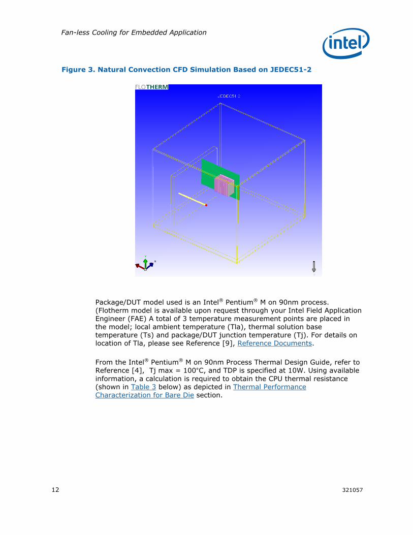
As mentioned in the earlier section, a JEDEC 51-2 standard is used to simulate a natural convection environment heat transfer and airflow. A CFD simulation based on the standard with a minor modification (shown in Figure 3) illustrates this example (with fin length orientation with respect to gravity). In natural convection, airflow can be assumed to free flow in the opposite direction of gravity; aligning the fins will then fulfill equations and theories mentioned in the earlier sections.
The CFD system boundary setup consists of a 12”x12”x12” polycarbonate enclosure, a wall to support Thermal Test Vehicle (TTV), a thermocouple support tube for local ambient temperature (Tla) measurement point, TTV/PCB, package/device under test (DUT), and thermal solution. The location of the Package/DUT is modeled exactly in the middle of the polycarbonate enclosure void, thermal solution, TTV, and thermocouple support tube - all modeled with respect to package/DUT. Figure 3 shows the model setup. For more information on JEDEC51-2 setup and material used, see Reference [9], Reference Documents.
Fan-less Cooling for Embedded Application
12 321057
Figure 3. Natural Convection CFD Simulation Based on JEDEC51-2
Package/DUT model used is an Intel® Pentium® M on 90nm process. (Flotherm model is available upon request through your Intel Field Application Engineer (FAE) A total of 3 temperature measurement points are placed in the model; local ambient temperature (Tla), thermal solution base temperature (Ts) and package/DUT junction temperature (Tj). For details on location of Tla, please see Reference [9], Reference Documents.
From the Intel® Pentium® M on 90nm Process Thermal Design Guide, refer to Reference [4], Tj max = 100°C, and TDP is specified at 10W. Using available information, a calculation is required to obtain the CPU thermal resistance (shown in Table 3 below) as depicted in Thermal Performance Characterization for Bare Die section.
Fan-less Cooling for Embedded Application
321057 13
Table 3. Dothan thermal resistance θJA for range of Tla
TLA (°C) 30 35 40 45 50 55 60
θJA°(C/W) 7.0 6.5 6.0 5.5 5.0 4.5 4.0
Thermal solution modeled in the CFD is a 50x50x30 mm with optimized parallel plate fins (calculated in Table 1).
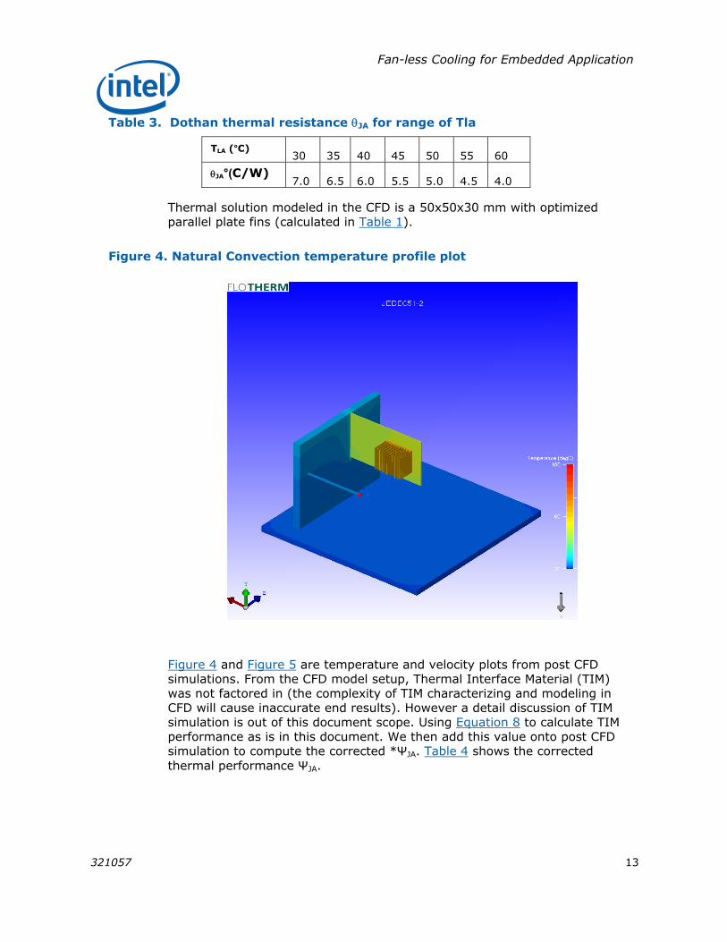
Figure 4. Natural Convection temperature profile plot
Figure 4 and Figure 5 are temperature and velocity plots from post CFD simulations. From the CFD model setup, Thermal Interface Material (TIM) was not factored in (the complexity of TIM characterizing and modeling in CFD will cause inaccurate end results). However a detail discussion of TIM simulation is out of this document scope. Using Equation 8 to calculate TIM performance as is in this document. We then add this value onto post CFD simulation to compute the corrected *ΨJA. Table 4 shows the corrected thermal performance ΨJA.

Fan-less Cooling for Embedded Application
14 321057
Table 4. Thermal Performance With TIM Resistance Factored In (Component Level)
Tla (°C) Tj (°C) ψTIM (°C/W) *ψJA (°C/W)
33.04 77.55 0.17 4.62
NOTE: Referring to Shin-Etsu TIM datasheet, X23-7783D contact resistance is 7.3 mm2K/W.
Figure 5 Natural Convection Velocity Particle Plot
In summary, for a single heat source (which is the DUT) cooled with an optimized parallel plate fin in JEDEC51-2 system boundary setup, one can expect a thermal performance of the thermal solution *ΨJA =4.62°C/W. The maximum allowable local ambient temperature would be 55°C or below as shown in Table 3. Take note that the final thermal performance *ΨJA could differ pending on what TIM is used; the higher performance TIM used the lower final thermal performance.

Fan-less Cooling for Embedded Application
321057 15
System Level CFD
This section depicts a specific system level example for analysis. The goal is to enable the system designer to understand and compare the difference between system level and component level CFD. It also gives an opportunity to further illustrate how CFD predicts an optimized natural convection heatsink performance under predefined system boundary conditions. The CFD example illustrated here is a 12.1” touch screen LCD – vertical standing POS system; refer to Figure 6. The enclosure is an aluminum box chassis with external dimension of 300x250x65 mm. The enclosure is simulated with top and bottom vent openings; the total FAR (Free Area Ratio) is set to 20% for both top and bottom vents. Holes pattern for the vents are 5mm hexagons uniformly distributed across the entire top and bottom surface.
Figure 6. System level CFD - 12.1" POS (vertical)

Fan-less Cooling for Embedded Application
16 321057
There is a polyimide insulating film separating the LCD from an SBC (Single Board Computer) and other peripherals. Right above the SBC is a DC-DC power PCB, 2.5” HDD and a CD ROM drive are modeled at the side of SBC (shown in the figure as silver color blocks). A 12.1” LCD is located right behind the insulating film. The SBC orientation as shown in the figure above is to accommodate side accessible I/O ports and position the processor at the bottom closest to the vents. The processor is placed at the lowest region of the enclosure to deliver fresh cooler air from the bottom vent openings. SBC is an Embedded Platform for Industrial Computing (EPIC) small form factor board with the Intel® Pentium® M processor built on 90nm paired with the Intel® 855GME Memory Controller Hub (GMCH) and Intel® 82801DB I/O Controller Hub 4. The thermal solution is a 50x50x30mm mentioned in previous section. The orientation of the heatsink is aligned such that its plate fins are paralle to the direction of gravity.
Table 5 below is a list of components used in the CFD simulation; most of the materials are found in the Flotherm* built-in library. An additional column of power budget is for reference only.
Table 5. List of components material and power used in the CFD simulation
Component Material Power (W)
12.1” LCD Alumina -
Insulating Film Polyimide -
Enclosure Al 6063 -
Power Board FR4 6 (assume)
Capacitors Ethylene Glycol -
Connectors Polycarbonate -
2.5” HDD Alumina 0.6
CD ROM Alumina -
I/O ports Polycarbonate -
EPIC SFF FR4 4 (assume)
SODIMM Heat Block 3.6
CPU Heatsink Al 6063
MCH Heatsink Al 6063
CPU Complex model 10
MCH Complex model 4.3
ICH Complex model 2.5
From Table 5, a single scenario example is used to illustrate system level CFD. Some components are models only with material and in real application it may dissipate power. It is up to the user to specify this per their power budget estimate. Most of the components are modeled as airflow restriction
Fan-less Cooling for Embedded Application
321057 17
rather than thermal dissipation in the simulation. The focus is on CPU, MCH, and I/O Controller Hub; more details and finer meshing are put within this area in the simulation. The total system is assumed to dissipate approximately 30W; this assumption is biased towards processor and chipset and is not likely to happen in a real world application. This example caters to the worst case scenario simulation for a processor and chipset.
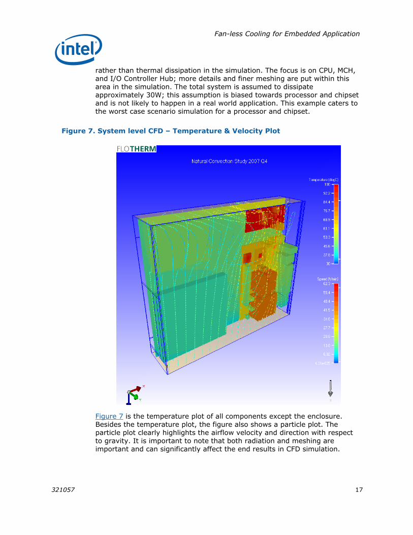
Figure 7. System level CFD – Temperature & Velocity Plot
Figure 7 is the temperature plot of all components except the enclosure. Besides the temperature plot, the figure also shows a particle plot. The particle plot clearly highlights the airflow velocity and direction with respect to gravity. It is important to note that both radiation and meshing are important and can significantly affect the end results in CFD simulation.

Fan-less Cooling for Embedded Application
18 321057
Table 6. Thermal Performance of the CPU in System Level CFD
Tla (°C) Ts (°C) Tj (°C) ΨTIM (°C/W) *ΨJA (°C/W)
31.0 72.98 76.58 0.17 4.728
Local ambient temperature shown in table above is an average temperature surrounding the CPU heatsink. It is the user’s responsibility to make sure several measurement points are used for best approximation of the local ambient temperature within the system boundary.
Conclusion In summary this white paper serves as a reference solution to fanless cooling for Intel embedded applications. First emphasis is on fundamental and theories for optimal fin spacing. Engineers can fully utilize this hand calculation analytic to approximate optimal fin spacing. Next perform a component level detail CFD simulation to characterize the thermal solution for Intel Architecture. Finally simulate a system level CFD with boundary condition for the application.
Fan-less Cooling for Embedded Application
321057 19
Authors
Chun Howe Sim is a Thermal Mechanical Application Engineer with ECG at Intel Corporation.
Jason Loh is a Thermal Mechanical Application Engineer with ECG at Intel Corporation.
Acronyms
CFD Computational Fluid Dynamic
CPU Central Processing Unit
DOE Design on Experiment
DUT Device Under Test
ECG Embedded Communication Group
EPIC Embedded Platform for Industrial Computing
FAR Free Area Ratio
FCBGA Flip Chip Ball Grid Array
Gr Grashof number
IA Intel Architecture
ICH I/O Controller Hub
IHS Integrated Heat Spreader
MCH Memory Controller Hub
PCB Printed Circuit Board
PDF Power Density Factor
Pr Prandtl number
Ra Rayleigh number
Re Reynolds number
SBC Single Board Computing
TDP Thermal Design Power
TIM Thermal Interface Material
TTV Thermal Test Vehicle
ULV Ultra Low Voltage
TJ Junction Temperature
TC Case Temperature
TS Heatsink Temperature
TLA Local Ambient Temperature

Fan-less Cooling for Embedded Application
20 321057
Reference Documents Material and concepts available in the following documents may be beneficial when reading this document:
Ref #
Document Document Number
1 Fundamentals of Heat and Mass Transfer, 6th Edition, FP Incropera, DP Dewitt, TL Bergman, Lavine AS, John Wiley & Sons, Inc.
N/A
2 Introduction to Thermal & Fluid Engineering, DA Kaminski, MK Jensen, John Wiley & Sons, Inc.
N/A
3 ULV Intel® Celeron® M Processor @ 600MHz for fanless set top box application
D18741
4 Intel® Pentium® M Processor on 90nm process for embedded application TDG
302231
5 Intel® Celeron® M Processor ULV373, Intel® 852GM GMCH & Intel® 82801DB ICH4 TDG for EST
313426
6 Thermal Modeling of Isothermal Cuboids & Rectangular Heat Sink Cooled by Natural Convection, JR Culham, MM Yovanovich, Seri Lee, IEEE transactions on components, packaging and manufacturing technology part A, Vol18, No3 Sept 1995
N/A
7 Frigus Primore, A volumetric Approach to Natural Convection N/A
8 Design for manufacturability of forced convection air cooled fully ducted heat sinks, Electronics Cooling, Volume 12, No. 3, August 2007
N/A
9 EIA/JEDEC51-2 Standard – Integrated Circuits Thermal Test Method Environment Conditions – Natural Convection (Still Air)
N/A
10 TC attachment power point foils (internal) N/A

Fan-less Cooling for Embedded Application
321057 21
INFORMATION IN THIS DOCUMENT IS PROVIDED IN CONNECTION WITH INTEL® PRODUCTS. NO LICENSE, EXPRESS OR IMPLIED, BY ESTOPPEL OR OTHERWISE, TO ANY INTELLECTUAL PROPERTY RIGHTS IS GRANTED BY THIS DOCUMENT. EXCEPT AS PROVIDED IN INTEL’S TERMS AND CONDITIONS OF SALE FOR SUCH PRODUCTS, INTEL ASSUMES NO LIABILITY WHATSOEVER, AND INTEL DISCLAIMS ANY EXPRESS OR IMPLIED WARRANTY, RELATING TO SALE AND/OR USE OF INTEL PRODUCTS INCLUDING LIABILITY OR WARRANTIES RELATING TO FITNESS FOR A PARTICULAR PURPOSE, MERCHANTABILITY, OR INFRINGEMENT OF ANY PATENT, COPYRIGHT OR OTHER INTELLECTUAL PROPERTY RIGHT. Intel products are not intended for use in medical, life saving, or life sustaining applications.
Intel may make changes to specifications and product descriptions at any time, without notice.
This paper is for informational purposes only. THIS DOCUMENT IS PROVIDED "AS IS" WITH NO WARRANTIES WHATSOEVER, INCLUDING ANY WARRANTY OF MERCHANTABILITY, NONINFRINGEMENT, FITNESS FOR ANY PARTICULAR PURPOSE, OR ANY WARRANTY OTHERWISE ARISING OUT OF ANY PROPOSAL, SPECIFICATION OR SAMPLE. Intel disclaims all liability, including liability for infringement of any proprietary rights, relating to use of information in this specification. No license, express or implied, by estoppel or otherwise, to any intellectual property rights is granted herein.
BunnyPeople, Celeron, Celeron Inside, Centrino, Centrino logo, Core Inside, Dialogic, FlashFile, i960, InstantIP, Intel, Intel logo, Intel386, Intel486, Intel740, IntelDX2, IntelDX4, IntelSX2, Intel Core, Intel Inside, Intel Inside logo, Intel. Leap ahead., Intel. Leap ahead. logo, Intel NetBurst, Intel NetMerge, Intel NetStructure, Intel SingleDriver, Intel SpeedStep, Intel StrataFlash, Intel Viiv, Intel vPro, Intel XScale, IPLink, Itanium, Itanium Inside, MCS, MMX, Oplus, OverDrive, PDCharm, Pentium, Pentium Inside, skoool, Sound Mark, The Journey Inside, VTune, Xeon, and Xeon Inside are trademarks or registered trademarks of Intel Corporation or its subsidiaries in the U.S. and other countries. *Other names and brands may be claimed as the property of others.
Copyright © 2008 Intel Corporation. All rights reserved.
§

Fan-less Cooling for Embedded Application
22 321057