faq optimizer4d en - qass faq - en.pdf · quality automation systeme software ... physical basics 5...
TRANSCRIPT

QASS GmbHQuality Automation Systeme Software Schoellinger Feld 2858300 Wetter, GermanyTel.: +49 (0) 2335 8020-0Fax: +49 (0) 2335 8020-20
[email protected].: DE215478481
Volksbank Bochum Witten eGBLZ: 430 601 29Kto.: 861 482 400
Comm. register: Hagen HRB 5423CEO / President:Ulrich Seuthe
BIC: GENODEM1BOCIBAN: DE21430601290861482400
Optimizer4D - FAQ
Table of contents
Physical basics 5What does the Optimizer4D display? 5
How does the display in frequencies work? 6
How do the acoustic emission sensors work? 6
Do crack signals occur in a certain frequency range? 6
We have strong noise in our production process (due to cooling water of drive systems). Does that have a negative e� ect on the measuring result? 7
Can a measuring result be falsifi ed by an echo? 7
Optimizer4D - FAQ
2 / 20
Application fi elds 7What kind of advantages does the Optimizer4D o� er compared to other crack detection systems? 7
Is the Optimzer4D able to examine a work piece subsequently? 8
Is the Optimizer4D able to recognize cracks at tempering (inductive hardening)? 8
Is it possible for the Optimizer4D to monitor the fl ow properties of liquids like oil or water in the machine? 8
Is the Optimizer4D able to continue measuring while parameters within a pro-cess change – for instance the inductor frequency or cutting tool condition? Is a tool monitoring possible? 9
Is the Optimizer 4D able to determine the exact location of a crack inside a work piece? 9
Is the Optimizer4D also suitable for small batch series? 9
How many machines can be monitored with an Optimizer4D? 10
Is this system mobile applicable? 10
Is the Optimizer4D delivered with an uninterrupted power supply (UPS)? 10
How sensitive does the Optimizer4D react to voltage drop or breakdown? 10
Measurements / weight 10
Test measuring 11How long does a test measuring last? 11
How is a test measuring prepared? 11
How many test work pieces have to be treated for a test measuring? 11
Measuring chain/Measuring sensitivity 11Details of the measuring chain? 12
How sensitive is the Optimizer4D’s measuring capacity? 12
How small are the fi nest cracks the Optimizer4D is able to detect? 12
Is it possible to detect cracks found by the Optimizer4D with magnetic particle testing or eddy current testing? 13
How long does the measuring evaluation take? How long is the period between

Optimizer4D - FAQ
3 / 20
end of measuring and the defective-signal? 13
Parameterization / Operation 13How is the crack detection parameterized? 14
How does the coupling to the production machine work to enable control and regulation? 14
Is it possible to limit the measuring time to a certain period? 14
Is it possible to start the measuring time delayed? 15
How long does it take to start the Optimizer4D self-test after end of measuring? 15
How long does the self-test take? 15
Is a long-time measuring possible? 15
Data storage 15How is the measuring data stored? Is there a possibility for an export? 16
Is it possible to save measuring data to an external computer? 16
Is it possible to save only part of the measuring data like the frequency band – due to a lack of storage? 16
Data safety: Can the extensive system functions be protected from unauthorized access? 16
Support / service / purchase procedure 16How long is the life of the sensors? 17
Why the annual calibration? 17
Where are the service locations? 17
Can I get telephone support? 17
How long is the waiting time for service on site? 17
Which possibilities do I have when a measuring device breaks down? 18
Is it possible to obtain a remote-support on an Optimizer4D, e. g. via team view-er? 18
Does QASS o� er support for the Optimizer4D? 18
How long is the delivery period for the QASS Optimizer4D? 18

Optimizer4D - FAQ
4 / 20
What does an Optimizer4D cost? How much postage do I have to pay? 19
Can I rent a device? 19
Are there Optimizer4D manuals or training material? Do you o� er an Optimi-zer4D training? 19
Is it possible to conclude a maintenance contract and by this to keep the wear- and spare parts cost low? 19
Which wear parts are contained in the device and what are their maintenance intervals? 19
How long is the delivery time for the spare parts? 19
Which kind of warranty does QASS o� er on the Optimizer4D? 20
How is the annual calibration performed? 20
How much does the annual calibration cost? 20

Optimizer4D - FAQ
5 / 20
Physical basics What does the Optimizer4D display?
Process optimizing and crack detection with the QASS Optimizer4D work on the basis of analysing solid borne emission signals, also known as acoustic emis-sion. The Optimizer4D displays the production process in a three-dimensional diagram with the axes time (x), frequency (z) and amplitude (y). The measuring device has to be adjusted on the specific production process.
Cracks can be easily and automatically detected due to their characteristic form in the three-dimensional diagram. Moreover, a qualification of other process parameters is possible. Therefore, it makes sense to adjust the measuring device to the desired state of the production process. Deviations later can be detected automatically by the tools “crack detection” or ”pattern recognition”. The adjustment of the desired state is a prerequisite for this.
Example: An inductor at an inductive hardening machine shall be monitored. The inductor e. g. delivers a steady frequency band at roughly 32 kHz. If there are deviations in frequency or amplitude, the Optimizer4D gives a warning signal as soon as the threshold values are exceeded or fall below that limit.
This operating principle can be transferred to many different industrial produc-tion processes.
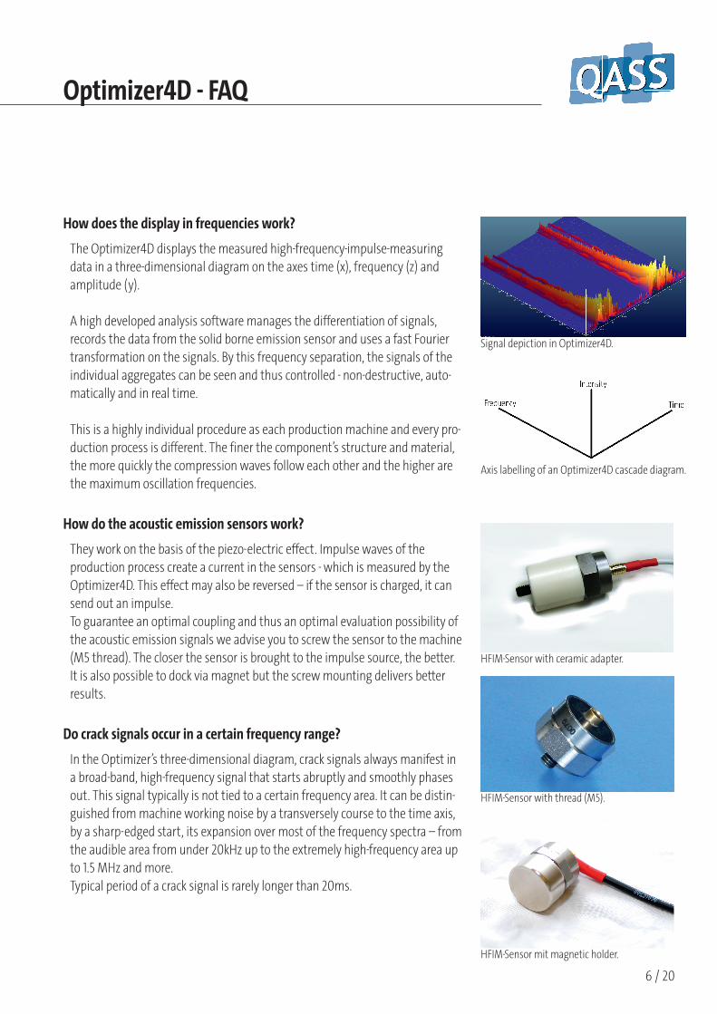
Three-dimensional display of the HFIM signals on the axes time (right), frequency (left) and amplitude (vertically).
Optimizer4D - FAQ
6 / 20
Signal depiction in Optimizer4D.
Axis labelling of an Optimizer4D cascade diagram.
HFIM-Sensor mit magnetic holder.
HFIM-Sensor with thread (M5).
HFIM-Sensor with ceramic adapter.
How does the display in frequencies work?
The Optimizer4D displays the measured high-frequency-impulse-measuring data in a three-dimensional diagram on the axes time (x), frequency (z) and amplitude (y).
A high developed analysis software manages the differentiation of signals, records the data from the solid borne emission sensor and uses a fast Fourier transformation on the signals. By this frequency separation, the signals of the individual aggregates can be seen and thus controlled - non-destructive, auto-matically and in real time.
This is a highly individual procedure as each production machine and every pro-duction process is different. The finer the component’s structure and material, the more quickly the compression waves follow each other and the higher are the maximum oscillation frequencies.
How do the acoustic emission sensors work?
They work on the basis of the piezo-electric effect. Impulse waves of the production process create a current in the sensors - which is measured by the Optimizer4D. This effect may also be reversed – if the sensor is charged, it can send out an impulse. To guarantee an optimal coupling and thus an optimal evaluation possibility of the acoustic emission signals we advise you to screw the sensor to the machine (M5 thread). The closer the sensor is brought to the impulse source, the better. It is also possible to dock via magnet but the screw mounting delivers better results.
Do crack signals occur in a certain frequency range?
In the Optimizer’s three-dimensional diagram, crack signals always manifest in a broad-band, high-frequency signal that starts abruptly and smoothly phases out. This signal typically is not tied to a certain frequency area. It can be distin-guished from machine working noise by a transversely course to the time axis, by a sharp-edged start, its expansion over most of the frequency spectra – from the audible area from under 20kHz up to the extremely high-frequency area up to 1.5 MHz and more. Typical period of a crack signal is rarely longer than 20ms.

Optimizer4D - FAQ
7 / 20
We have strong noise in our production process (due to cooling water of drive systems). Does that have a negative e� ect on the measuring result?
Rarely. Usually, the crack signals can be clearly distinguished from the work noise of a production process. Moreover, frequency ranges can be masked and filtered from the measuring results. In tool monitoring it is important if the signals can be distinguished temporally or spatially from the work noise of the process – which mostly is not possible. A test measuring can obtain clarity.
Can a measuring result be falsifi ed by an echo?
Echoes and resonances are always part of the solid borne emission measuring and the process characteristic. Either they exist or not – this is not important for the measuring and evaluation by HFIM because in any case you get a typical image of the process.
Application fi eldsWhat kind of advantages does the Optimizer4D o� er compared to other crack detection systems?
Conventional structure-borne noise measuring systems usually work on a two-dimensional time (x-axis) and amplitude (y-axis) display. Optimizer4D additio-nally measures in the frequency ranges. In straightening processes for instance you measure in the default range of 512 discrete frequencies. This greatly improves signal-to-noise-ratio because cracks usually generate high frequencies while working noise of the machine noises does not.
This measuring range can be adjusted and filtered customized to your requi-rements, background- and working noise of the machine can be suppressed. Cracks in material are recognized by a characteristic signal and are detected automatically. At the same time it is possible to recognize patterns.
In the upper diagram, you see the two-dimensio-nal signal display. An automatic evaluation with this method is hardly possible. The signal-to-noise-ratio is very small.
The lower diagram shows the same signal in the three-dimensional display of the Optimizer4D.Most conspicuous is the signifi cantly increased se-lectivity due to the three-axle display of the same signal. In noise-free ranges, an automatic crack de-tection is simple and surely possible.
Optimizer4D - FAQ
8 / 20
Inductive hardening.
Is the Optimzer4D able to examine a work piece subsequently?
No. The measuring device detects cracks and process parameters only in real-time – that means in the moment they occur. A tool or work piece therefore cannot be measured subsequently after the processing. This can only be done during the actual production process.
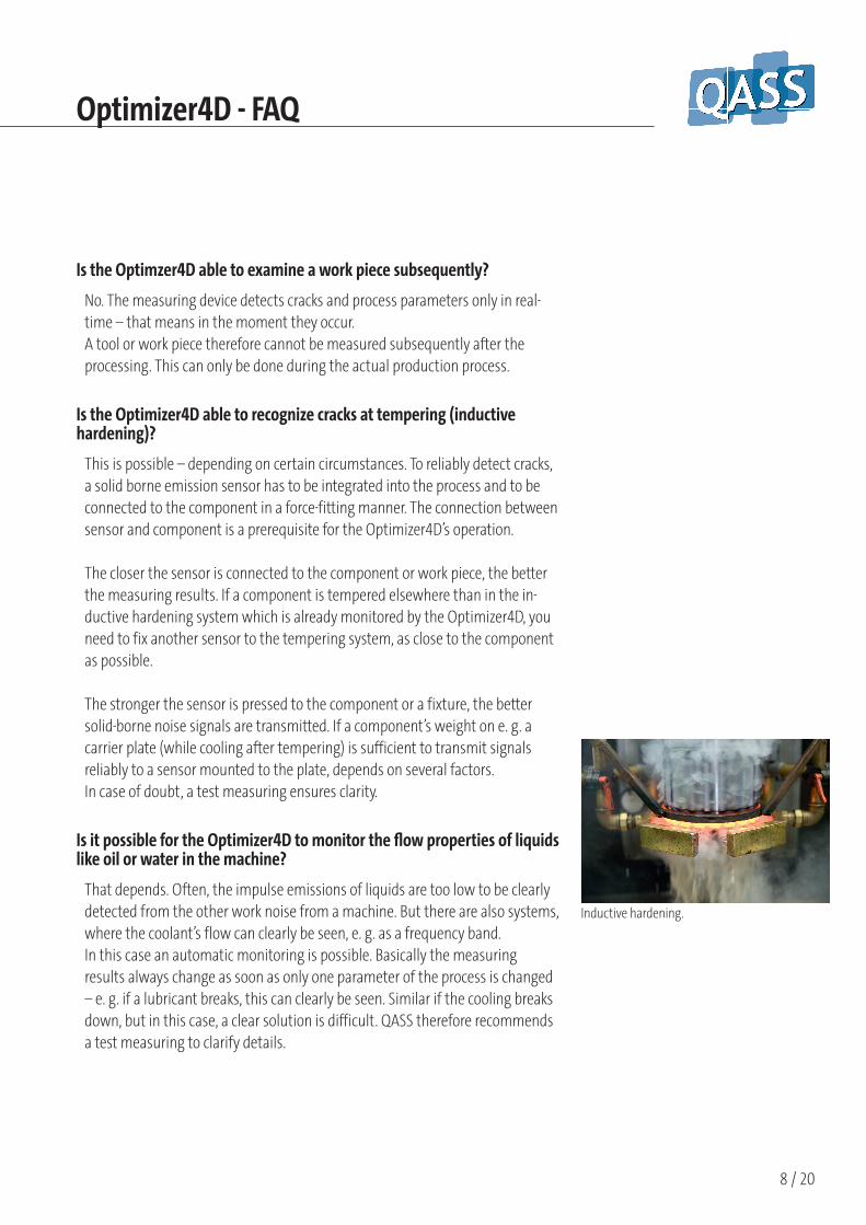
Is the Optimizer4D able to recognize cracks at tempering (inductive hardening)?
This is possible – depending on certain circumstances. To reliably detect cracks, a solid borne emission sensor has to be integrated into the process and to be connected to the component in a force-fitting manner. The connection between sensor and component is a prerequisite for the Optimizer4D’s operation.
The closer the sensor is connected to the component or work piece, the better the measuring results. If a component is tempered elsewhere than in the in-ductive hardening system which is already monitored by the Optimizer4D, you need to fix another sensor to the tempering system, as close to the component as possible.
The stronger the sensor is pressed to the component or a fixture, the better solid-borne noise signals are transmitted. If a component’s weight on e. g. a carrier plate (while cooling after tempering) is sufficient to transmit signals reliably to a sensor mounted to the plate, depends on several factors.In case of doubt, a test measuring ensures clarity.
Is it possible for the Optimizer4D to monitor the fl ow properties of liquids like oil or water in the machine?
That depends. Often, the impulse emissions of liquids are too low to be clearly detected from the other work noise from a machine. But there are also systems, where the coolant’s flow can clearly be seen, e. g. as a frequency band.In this case an automatic monitoring is possible. Basically the measuring results always change as soon as only one parameter of the process is changed – e. g. if a lubricant breaks, this can clearly be seen. Similar if the cooling breaks down, but in this case, a clear solution is difficult. QASS therefore recommends a test measuring to clarify details.

Optimizer4D - FAQ
9 / 20
Is the Optimizer4D able to continue measuring while parameters within a process change – for instance the inductor frequency or cutting tool condition? Is a tool monitoring possible?
The Optimizer is able to continue measuring. For a successful crack- or state-of-tool-recognition we recommend to teach the parameters before the working procedure and to transmit to the Optimizer4D during the process; to react to other parameters if necessary.
On the other hand, crack signals can clearly be distinguished from other work noise of a process. The Optimizer4D is able to monitor several parameters of a process and alter the parameterization afterwards automatically – e. g. a certain frequency band or the state of a certain tool.
Is the Optimizer 4D able to determine the exact location of a crack inside a work piece?
Not yet. We are working on a solution.
Is the Optimizer4D also suitable for small batch series?
Basically many different combinations of work pieces, materials and production processes can be monitored with the Optimizer4D. However, the automatic crack detection needs an exact parameterization of process and work piece. If the work piece changes, it is possible, that the crack signal changes, too. Each work piece has to be parameterized once in the Opti-mizer4D. The measuring device is able to store hundreds of work pieces – the list of crack detection parameters for work pieces is only limited by the databa-se storage space.
It is possible to adjust the measuring device automatically to a previously defi-ned parameter set – e. g. by means of the control technology PLC. Now chan-ging work pieces or process parameters can be monitored – if they had been set before start of production.

Optimizer4D - FAQ
10 / 20
QASS Optimizer4D with housing and signal lamp (optional).
QASS Optimizer 4D, standard version with pre-amplifi er and sensors.
How many machines can be monitored with an Optimizer4D?
Basically, an Optimizer4D is able to execute only one measuring at a time. The measuring device can receive signals from up to four data channels. These channels can be evaluated independently from one another and taken for control and regulation. However, if you start measuring, all data channels are started at the same time. If, for instance, the device recognizes a crack signal on one of the channels, this channel can be evaluated separately from other data channels – e. g. for control and regulation of the production machine. If you want to use the Optimizer4D at several machines, the machines have to be clocked synchronously – regarding the starting point and the point of end of measuring.
Is this system mobile applicable?
Yes. We offer several housings for the Optimizer4D: different mobile variations, (e. g. in a portable suitcase) or in a protective housing (e. g. for operation at a manual straightening press). There is a tough mobile case available (QASE) that includes a touchscreen-monitor. Standard is the mounting into a control cabinet with a machine control connection (e. g. PLC).
Is the Optimizer4D delivered with an uninterrupted power supply (UPS)?
Indeed, a uninterrupted power supply (UPS) is a standard component of the machine. This component consists of several supercapacitors (supercaps). In case of a blackout, the UPS enables the measuring device to shutdown properly. This will prevent loss of data to a major extent. Just the measuring data of the work piece which was processed in the moment of the blackout will be lost.
How sensitive does the Optimizer4D react to voltage drop or breakdown?
If the device is equipped with an UPS, there should be no problems in case of a power failure once in a while. If there are many power downs without charging the capacitors, data errors or even data loss is possible.
Optimizer4D, QASE mobile case.
Measurements / weightControl cabinet
Protectivecasing
Protective c. with lamp
QASE
Length (cm) 20 34 34 45,5Width (cm) 27,4 34 34 56Height (cm) 13,2 24 35 26,5Weight (kg) 9 18 18,5 23,5

Optimizer4D - FAQ
11 / 20
Test measuringHow long does a test measuring last?
The test measuring period takes minimum three hours at a production machi-ne. Additionally you need time to prepare the test measuring – details of the machine to be monitored have to be exchanged preliminary to the test measu-ring between QASS and you.
It is necessary to set clear goals before start of measuring. Moreover, it is helpful if the work pieces treated during the test measuring are disposable for a second test – e. g. with another, maybe destructive, testing method.
QASS does the test measuring taking the production process in considerati-on– but it is necessary to calculate a certain period for the measuring device’s adjustment to the production process.The better the testing conditions, the more informative the measuring result. Support by a skilled machine operator during the test measuring is a necessary prerequisite.
How is a test measuring prepared?
You need certain preparations. We ask you to deliver us as much information concerning the machine and process as possible. Basically it is about the connection of the solid borne emission sensors / the sensors. They have to be brought as close to the place that shall be monitored as possible (e. g. a tool or a work piece).
To avoid pseudo-rejects, we recommend to mark the treated work pieces, to collect them and later do another testing on them (e. g. magnetic powder) –then you are able to interpret the Optimizer4D’s signals correctly. If you have done this interpretation once, often a subsequent testing becomes unnecessa-ry.
How many test work pieces have to be treated for a test measuring?
The more test work pieces are treated– the more reliable the result. It is not possible to name a special number, it also depends on the production process and on the work pieces. Experience has proved that it is very helpful to reserve a certain number of components for the test measuring.
Measuring chain/Measuring sensitivity
Optimizer4D - FAQ
12 / 20
Details of the measuring chain?
Sensor (optional: ceramic adapter for electrical decoupling) – several fixings (screwing, magnets) – preamplifier-Main unit Optimizer4D – measuring and analysis software Analyzer4D.
How sensitive is the Optimizer4D’s measuring capacity?
The sampling rate is 100MHz; 25.000 spectral lines per second are calculated and shown in real-time in the frequency-time-signal strength-diagram.
The Optimizer4D is a measuring computer with an efficient Linux-PC-system, equipped with a special and custom-made measuring hardware. The measu-ring hardware is constructed for the editing of high-frequency ultrasound signals up to 25 MHz
Typically, a pencil lead crack near the sensor (the so-called “Nielsen test” accor-ding to DIN EN 1330-9) creates a clearly recognizable deflection with the typical crack signal form.
Further technical details:• 100MHz sampling rate for up to four measuring channels • Storage of the measuring data (up to 25MB/s and channel) to the hard
drives (2 Terabyte storage space – su� cient for ca. 11 hours of measuring) • 24V I/O-unit for a direct communication with the machine unit (enables an
automatic process regulation)• Extensive software with numerous analysis- and statistic tools
How small are the fi nest cracks the Optimizer4D is able to detect?

Optimizer4D - FAQ
13 / 20
A crack in a work piece, detected by the Optimi-zer4D.
This depends – among other facts – on the work noise of the process which possibly may hamper the crack recognition if we have very small cracks and very broad-band, noisy processes.
Usually, if we have a good sensor coupling, the Nielsen test does function – a 0,5 mm pencil lead is cracked on the component – the crack signal occurs as a clearly recognizable deflection in the typical form (abrupt start, high-frequent and broad-band) on the measuring device’s screen.
Prerequisite: good coupling of the sensor as close to the component as possible – without dampening structures like bearings or drives between component and sensor.
Is it possible to detect cracks found by the Optimizer4D with magnetic particle testing or eddy current testing?
Often - but not always. It is possible that a crack in the component closes on the component’s surface during the processing. This crack now still exists inside of the component, but it is not visible because it‘s closed at the surface - a ma-gnetic particle testing or eddy current testing would not detect this crack. The Optimizer4D is able to even find these kind of cracks in the moment they occur.
How long does the measuring evaluation take? How long is the period between end of measuring and the defective-signal?
The system delivers a signal immediately after crack detection and during the forming process – 100ms after end of measuring at the latest.
Parameterization / Operation

Optimizer4D - FAQ
14 / 20
How is the crack detection parameterized?
The Opimizer4D software enables a distinction of measured crack signals in micro cracks, cracks and break. These three states are clearly parameterizable. Basically, the Optimizer4D automatic crack detection is provided by a clearly de-finable frequency band in combination with a clearly definable period of time.
Additionally it is possible to define a noise level which enables to only take energy values higher than this defined level into the energy analysis. The auto-matic crack detection can be started or terminated by external trigger signals – like PLC machine control.
The terms crack, micro crack and break are labels for different crack-paramete-rizations: for different definitions of frequency band, period of time and noise level. The machine is not able to recognize cracks or break just by itself, it has to be adjusted to each production process.
Measured data from processes are saved. This enables you to replay the measured data again and again – like a film, but made of solid borne emission signals. The crack parameterization can be applied to these recordings and can be adjusted to reliably set them to the requested parameter area.
The measuring system counts the crack-, micro crack- and break-events and dis-plays a warning on the screen or/and via the I/O-ports if the number of events should exceed threshold values.
How does the coupling to the production machine work to enable control and regulation?
Via interface Optimizer4D-PLC. The Optimizer4D has 16 to 24 input ports, confi-gurable by software parameters; also 8 to 16 output ports – they are configura-ble by the software, too. A Profibus connection is optional.
Is it possible to limit the measuring time to a certain period?

Optimizer4D - FAQ
15 / 20
Yes. You can run the measuring for a previously set period. It is also possible to terminate the measuring by a signal from the I/O-port or manually.
There are further possibilities: the crack detection can be switched off for each single channel so that the measuring continues but the crack detection runs only on the channels that are still switched on. You can also activate or deactiva-te the crack detection per I/O-port or per time limit.
Is it possible to start the measuring time delayed?
Yes. You can parameterize different delays for each input.
How long does it take to start the Optimizer4D self-test after end of measuring?
You have optimal testing conditions if the machine is idle. If the machine’s own working noise is slight, the self-test should work despite these movements, too.
How long does the self-test take?
Unique self-test: less than 100ms. If an error occurs, the self-test can be repea-ted to ensure measuring. This prolongs the testing time correspondently. If you repeat twice, the period is less than 300ms. In practice, more than two repeti-tions have been proved as unnecessary.
Is a long-time measuring possible?
Yes, even over a few days’ time. You have to consider this when ordering the system, as we need to install the correspondent memory space.
Data storage
Optimizer4D - FAQ
16 / 20
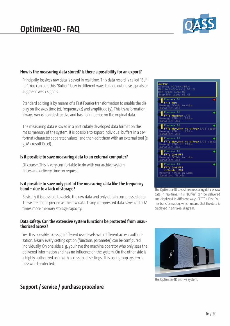
The Optimizer4D saves the measuring data as raw data in real-time. This “Bu� er” can be delivered and displayed in di� erent ways. “FFT” = Fast Fou-rier transformation, which means that the data is displayed in a triaxial diagram.
The Optimizer4D archive system.
How is the measuring data stored? Is there a possibility for an export?
Principally, lossless raw data is saved in real-time. This data record is called “Buf-fer”. You can edit this “Buffer” later in different ways to fade out noise signals or augment weak signals.
Standard editing is by means of a Fast-Fourier-transformation to enable the dis-play on the axes time (x), frequency (z) and amplitude (y). This transformation always works non-destructive and has no influence on the original data.
The measuring data is saved in a particularly developed data format on the mass memory of the system. It is possible to export individual buffers in a csv-format (character separated values) and then edit them with an external tool (e. g. Microsoft Excel).
Is it possible to save measuring data to an external computer?
Of course. This is very comfortable to do with our archive system.Prices and delivery time on request.
Is it possible to save only part of the measuring data like the frequency band – due to a lack of storage?
Basically it is possible to delete the raw data and only obtain compressed data. These are not as precise as the raw data. Using compressed data saves up to 32 times more memory storage capacity.
Data safety: Can the extensive system functions be protected from unau-thorized access?
Yes. It is possible to assign different user levels with different access authori-zation. Nearly every setting option (function, parameter) can be configured individually. On one side e. g. you have the machine operator who only sees the delivered information and has no influence on the system. On the other side is a highly authorized user with access to all settings. This user group system is password protected.
Support / service / purchase procedure

Optimizer4D - FAQ
17 / 20
How long is the life of the sensors?
Basically, the sensors and cables are wear parts. The lifetime strongly depends on the application fields. If sensors are used in processes where they are exposed to regular movements or influences like cooling water, they have to be exchanged earlier than sensors without these influences.Usually, sensors and cables should work properly longer than two years. We recommend to keep wear parts in stock. Moreover, we recommend an annual calibration which is also important to adjust process parameters that might possibly have changed.
Why the annual calibration?
The annual calibration ensures that the system measures properly as it should. We recommend an annual calibration and remind our clients three months before the calibration is due.
Where are the service locations?
The QASS head office in Germany ensures a worldwide service to all our clients concerning training, process accompanying and repair – either by our service technicians or our distribution partners in • China (Hanghzou)• USA (Chicago)• Mexico (Iraputo)• Korea (Seoul)• Brazil (Sorocaba)• Japan (Hiroshima)• Argentina (Buenos Aires)
Can I get telephone support?
Yes. Our head office in Wetter/Ruhr offers a free telephone service technician telephone service on weekdays during the common office hours. We offer this service in German and English and are also able to give you support in Spanish, French, Portuguese, Turkish and Arabic.
How long is the waiting time for service on site?

Optimizer4D - FAQ
18 / 20
Urgent service is done by QASS as soon as possible. For common service calls, we have a lead time of approximately four weeks.
Which possibilities do I have when a measuring device breaks down?
Usually, QASS has the parameterization- and client settings of all clients’ measu-ring systems due to the annual calibration. This enables us to be able to send a chargeable substitute device with the corresponding parameters. Delivery time without customs is usually less than 24 hours. As soon as the client receives the device, he has to send the broken one to QASS immediately. It is a good option to have a substitute device in stock.
Is it possible to obtain a remote-support on an Optimizer4D, e. g. via team viewer?
Generally yes - you need to configure the network access over standard Ether-net connection. The Optimizer must obtain an internet connection. Therefore, Gateway- and DNS data must be entered in the Optimizer4D. If the Optimizer4D is connected to the internet, you can execute the Firefox internet browser (which is already installed). Team viewer can be installed afterwards (www.teamviewer.com; „download rpm“. You can ask us for details concerning this procedure).
There are other, easier possibilities to get remote support. We think it is best to configure the router with a so-called Port Forwarding on SSH Port (22).
Generally, we don’t support a wireless communication for Optimizer4D. In some cases, this is possible – we have had good results using the DLink DWR 512 router, for example.
Does QASS o� er support for the Optimizer4D?
Yes, Monday to Friday from 8.30 a. m. to 4.30 p. m. Usually, the support is free within the first year. The costs for the support afterwards are individual.
How long is the delivery period for the QASS Optimizer4D?

Optimizer4D - FAQ
19 / 20
Six to eight weeks.
What does an Optimizer4D cost? How much postage do I have to pay?
For prices on request contact [email protected] or dial ++49 (02335) 80200.Payment terms are individually fixed as the Optimizer4D is custom made due to the corresponding equipment.
Can I rent a device?
Yes. Leasing costs depend on the application fields and the QASS service technician’s effort and thus are fixed individually.
Are there Optimizer4D manuals or training material? Do you o� er an Optimizer4D training?
QASS offers a detailed Optimizer4D manual. We offer a profound training where additional material with detailed information is provided. A training concerning crack detection and process optimizing with the Optimizer4D is held regularly. Find the training dates on www.qass.net.
Is it possible to conclude a maintenance contract and by this to keep the wear- and spare parts cost low?
Yes. A maintenance agreement generally offers price advantages concerning the travelling costs for a calibration. The more QASS clients are in a certain region, the better the possibility to divide the travelling costs for a QASS technician.
Which wear parts are contained in the device and what are their mainte-nance intervals?
The cables are wear parts. The maintenance interval depends on the working environment of the cables. Sensors are spare parts, they have to be calibrated annually. Furthermore, QASS recommends to exchange the hard drive every second year. Cables, sensors and hard drives can be stored as spare parts and exchanged by the user himself. The exchange can be done by a QASS technician on request.
How long is the delivery time for the spare parts?

Optimizer4D - FAQ
20 / 20
Spare parts like sensors and cables are permanently in stock and can be dispat-ched the day the order is placed. If the delivery is not that urgent, spare parts are usually dispatched up to three days after receiving the order.
Which kind of warranty does QASS o� er on the Optimizer4D?
Warranty period is one year and starts with day of delivery. If the device should be calibrated within the course of this first year, the warranty is prolonged for one year. The total time of two years may not be extended.
How is the annual calibration performed?
Usually, the device is calibrated on the client’s place. This offers several advanta-ges: the calibration is more precise than on the QASS production place and the technicians can check if it is properly integrated in the process on site. It is also possible to send the device to QASS – but together with the entire measuring chain (measuring device, cable, preamplifier, sensors).
How much does the annual calibration cost?
600 € plus traveling costs.