fast kicker tests and bellows impedance at dafne.ppt · pdf file2 ports with short cicuits,...
TRANSCRIPT

FAST KICKERS TESTSFAST KICKERS TESTSAND
BELLOWS IMPEDANCE AT DAFNE
Fabio Marcellini LNF INFNFabio Marcellini, LNF- INFN
LCWS08 & ILC08N 16 20 2008 U i it f Illi i ChiNov 16-20, 2008 University of Illinois, Chicago
PRESENTATION OUTLINE
1. Design of a stripline kicker for beam injection in DAFNE storage rings.g g
2. HV tests and RF measurements of the kicker.3. DAFNE operation with the new kickers.
4. Realization of a stripline kicker for ILC damping ringring.
5. New DAFNE shielded bellows

1. DESIGN OF THE NEW DAFNE INJECTION KICKER
Input ports
EllipticalElliptical cross section
St i iStrip ceramic supportsHV
feedthrough
Outputports(LOAD)
Tapered stripline
BEAM
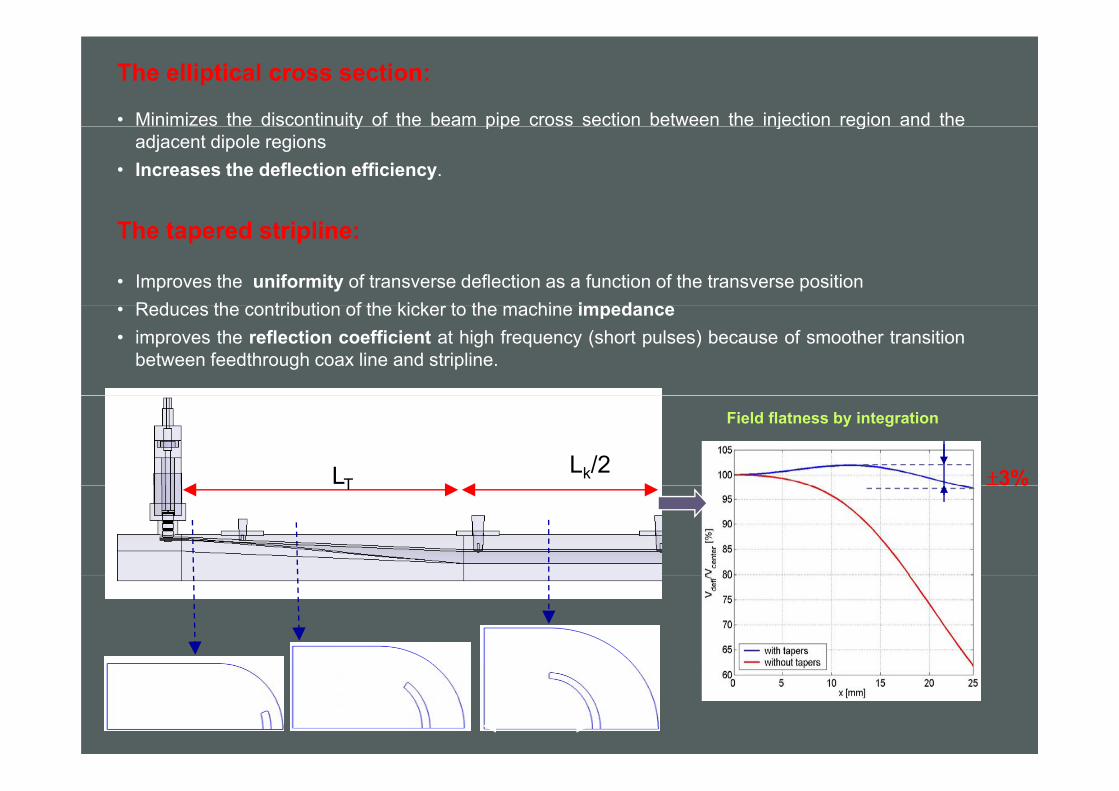
The elliptical cross section:
• Minimizes the discontinuity of the beam pipe cross section between the injection region and they p p j gadjacent dipole regions
• Increases the deflection efficiency.
The tapered stripline:
• Improves the uniformity of transverse deflection as a function of the transverse positionRed ces the contrib tion of the kicker to the machine impedance• Reduces the contribution of the kicker to the machine impedance
• improves the reflection coefficient at high frequency (short pulses) because of smoother transitionbetween feedthrough coax line and stripline.
Lk/2LT ±3%
Field flatness by integration
T 3%

injection kicker design parametersPARAMETERS
Beam Energy E [MeV] 510
Time spacing between bunches [ns] 2.7
Deflection [mrad] 5Total deflecting voltage VT [MV] 2.5
Total kicker length L [cm] ∼90Total kicker length L [cm] 90
Voltage per strip [kV] 45Input pulse length [ns] ∼ 5
Pulse length “seen” by bunches [ns] 10Pulse length seen by bunches [ns] ∼10
Max rep rate [Hz] 10

2. HV TESTSold pulserold pulser
(LNF)50 kV, 50 Ωfeedthrough LNF design
fastpulser (FID)
LNF design
(FID)
25 kV45 kV 25 kV45 kV
250 ns5 ns
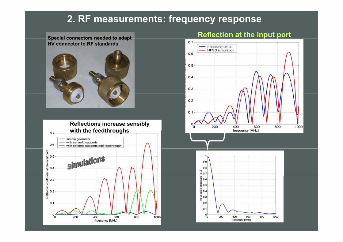
2. RF measurements: frequency response
Special connectors needed to adapt Reflection at the input portSpecial connectors needed to adapt HV connector to RF standards
Reflections increase sensiblywith the feedthroughs
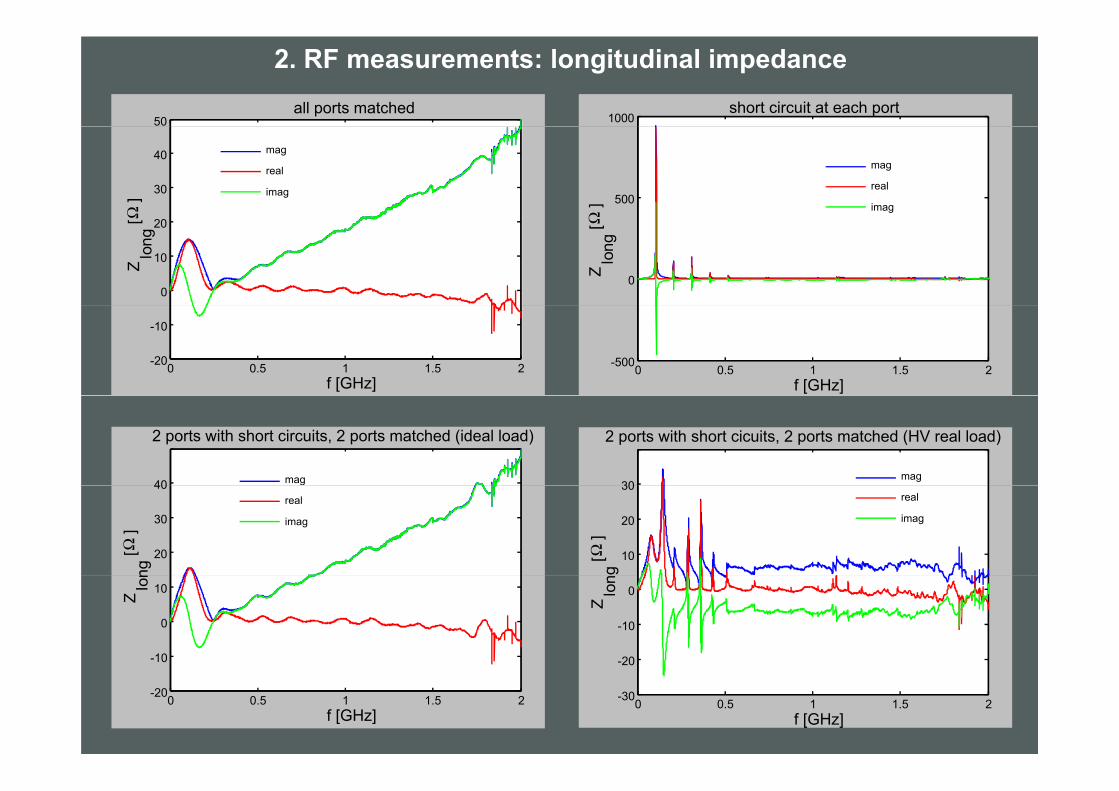
2. RF measurements: longitudinal impedance
50all ports matched
1000short circuit at each port
30
40 mag
real
imag
Ω] 500
mag
real
imag
Ω]
0
10
20
Zlo
ng[Ω
0Zlo
ng[Ω
0 0.5 1 1.5 2-20
-10
f [GHz]0 0.5 1 1.5 2
-500
f [GHz]
30
2 ports with short cicuits, 2 ports matched (HV real load)
mag40
2 ports with short circuits, 2 ports matched (ideal load)
mag
10
20
30
g[Ω
]
real
imag
20
30
40
ng[Ω
]
real
imag
-20
-10
0Z
lon
-10
0
10Zlo
n
0 0.5 1 1.5 2-30
20
f [GHz]0 0.5 1 1.5 2-20
f [GHz]

3. DAFNE operation with the new kickers
New kickers installed in the DAΦNE rings (Nov. 07)
e+ e-IP
Final version of the 45 kV FID pulsers has shown poor reliability. At present only 1 pulser of 4 is good. FID GmbH repaired and updated several times the broken components but a reliable solution has not yet been foundsolution has not yet been found. We never had the possibility to operate with the 4 pulsersworking together at the same timetime.We are now running with the old, long pulse system in both the rings.In e+ ring we have succesfully tested injection with a hybrid system connecting both the old pulser and the 45kV fast pulser topulser and the 45kV fast pulser to each kicker.

Injection with hybrid system
fast pulsefast pulse
kck1kck2
beam
Long and the fast pulses observed in sum at the scope.Taken from 2 striplines of the e+ ring kickers. Different attenuations for signals from the 2 striplines.

DAFNE beam oscillations with fast kickMeasured by the horizontal digital feedback system.Measured by the horizontal digital feedback system.
100, of 120, stored bunches with kicker pulse centered on bunch 50.bunch distance 2.7 ns.

DAFNE beam oscillations with fast kickrms oscillation amplitude of 100 stored bunches with
1,00
kicker pulse centered on bunch 50
0,60
0,80
0,20
0,40
0,10
0,12
0,00
0,20
1 11 21 31 41 51 61 71 81 91 101 111
0 06
0,08
0,04
0,06
Same plot with a scale in ns and amplified vertical scale
0,00
0,02
-150 -100 -50 0 50 100 150 200
and amplified vertical scale
Shows a tail of ~2% above noise level

Experience with FID pulsers
First results of operation with FID fast pulsershave been very promising.
Routine operation with 45kV FIDs not allowedb f th i li bilitbecause of their very poor reliability.
After increasing ß function in the kicker region andchanging the beam orbit in the septa, we tried
f ll i j ti ith 24kV 5 FIDsuccessfully injection with a 24kV, 5ns FID.
Pulse shape is the same of the 45kV FID, justlower voltage amplitude.
We used this 24 kV FID for lab tests and neverhad problems up to now.
We decided to give up the 45 kV FIDs and try togo on with the 24 kV units.
It is possible to have eight 24kV pulsers at thecost of the four 45 kV FIDs. Enough for both thei
The 24kV FID used for rings. lab HV tests

Present situation
horizontalfdbk
horizontalfdbksituation fdbkfdbk
e+ ring
old pulser old pulser
e ringe- ring
old pulserold pulser
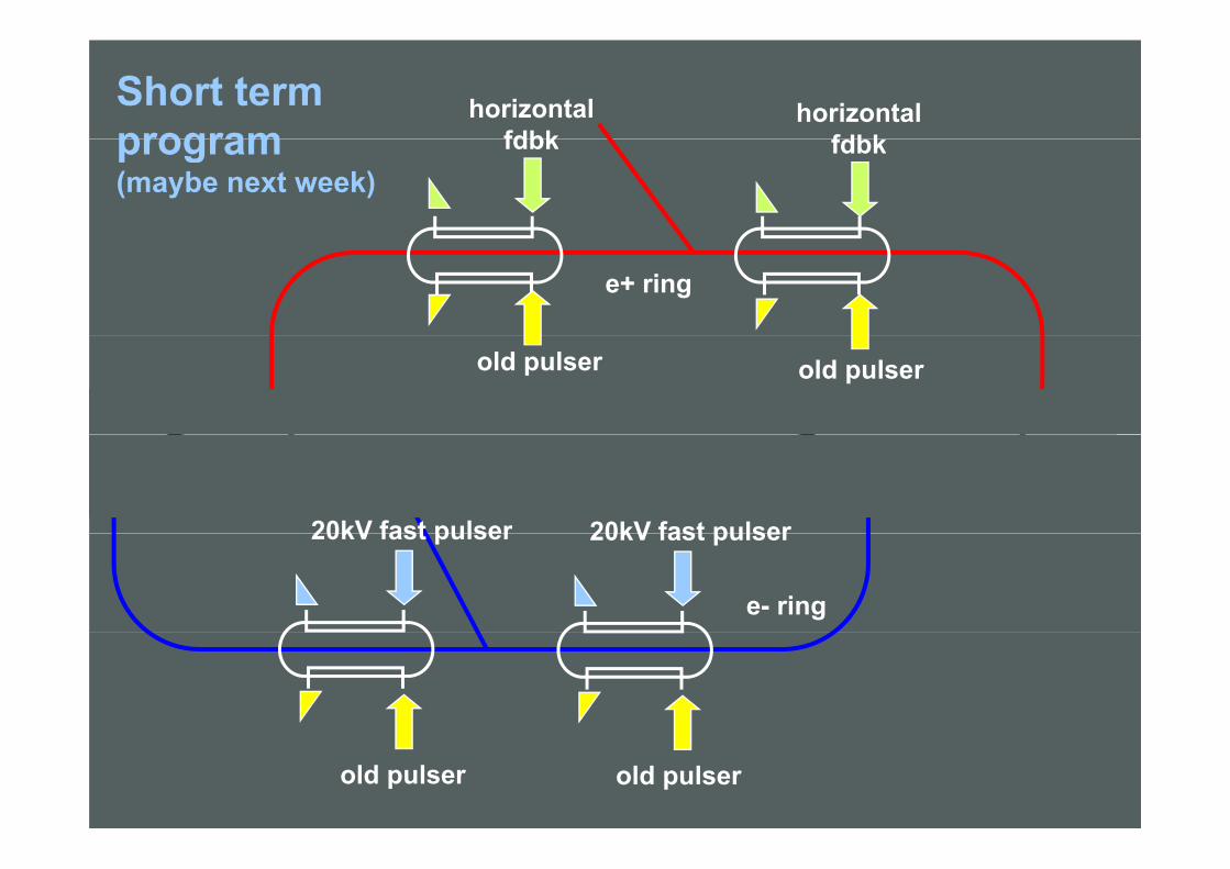
Short term program
horizontalfdbk
horizontalfdbkprogram
(maybe next week)fdbkfdbk
e+ ring
old pulser old pulser
20kV fast pulser 20kV fast pulser
e- ring
20kV fast pulser 20kV fast pulser
old pulserold pulser

Longer term programprogram
20kV fast pulser 20kV fast pulser
e- / e+ ring
20kV f t l20kV f t l
An additional stripline kck will be installed in e+ ring for the horizontal fdbk
20kV fast pulser20kV fast pulser
An additional stripline kck will be installed in e+ ring for the horizontal fdbk.
Operation with hybrid solution also possible. More flexible in case of failure of FID pulsersMore flexible in case of failure of FID pulsers.

4. A KICKER FOR ATFATF PRESENT KICKER
ATF TAPERED STRIPLINE KICKER
B th th t t
Deflecting field along the longitudinal
Both the structures have been simulated with HFSS
structure axis
Blue: straight section striplinepRed: tapered stripline

SIMULATION RESULT COMPARISON
deflecting voltage on the vertical axis
deflecting voltage on the horizontal axis
Input port reflectionsLongitudinal coupling
impedance
Transfer impedances
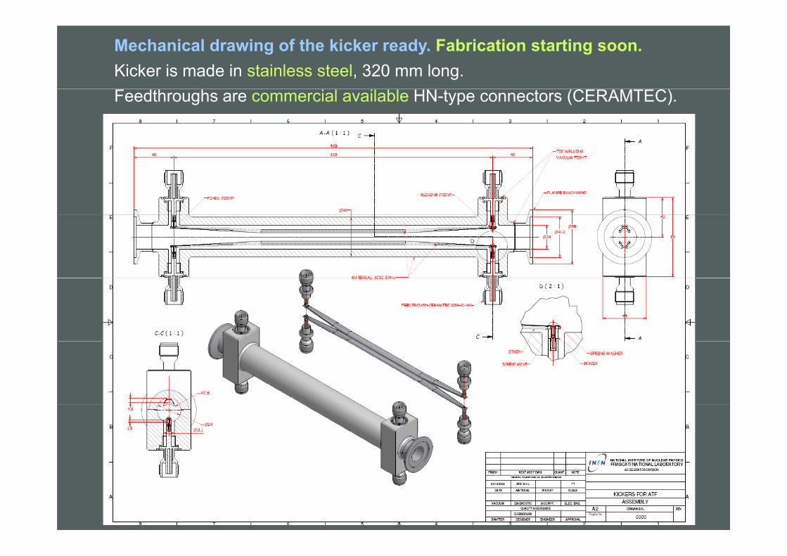
Mechanical drawing of the kicker ready. Fabrication starting soon.Kicker is made in stainless steel, 320 mm long.Feedthroughs are commercial available HN-type connectors (CERAMTEC).

5. The new DAFNE bellows
For the DAFNE upgrade, vacuum chamber modifications have concerned:
1. new interaction regions,
2. new stripline injection kickers,
3. all ion clearing electrodes removed in the electron ring.
4. new bellows
Low impedance design of the new vacuum chamber componentsLow impedance design of the new vacuum chamber components
0.012
m]
0.008
oupl
ing
Imp
[Ohm
Bellows beam coupling impedance
0 1 2 3 40
0.004
frequency [GHz]
Co Bellows beam coupling impedance
obtained by HFSS
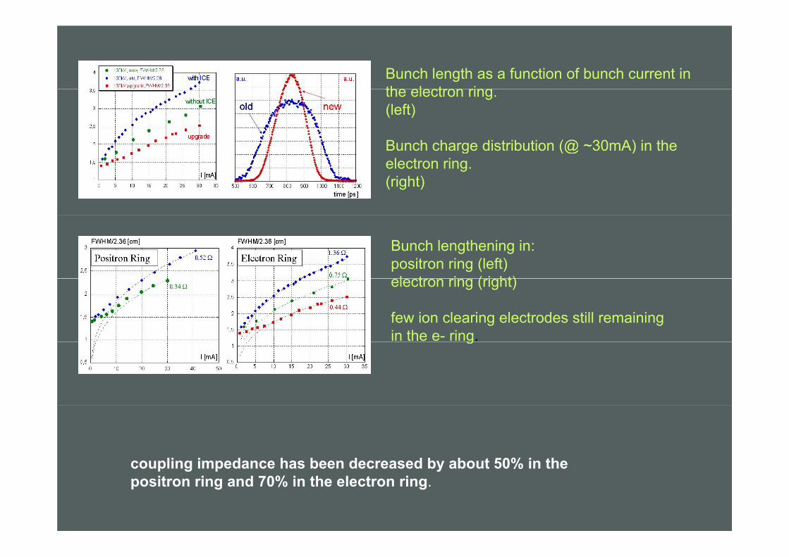
Bunch length as a function of bunch current in the electron ringthe electron ring.(left)
Bunch charge distribution (@ ~30mA) in the g (@ )electron ring.(right)
Bunch lengthening in:positron ring (left) l t i ( i ht)electron ring (right)
few ion clearing electrodes still remainingin the e- ring.g
coupling impedance has been decreased by about 50% in thecoupling impedance has been decreased by about 50% in the positron ring and 70% in the electron ring.

The shield is composed of:
DRAWING OF THE NEW DAFNE BELLOWS Designed for a circular cross section (ø 88 mm) chamber.The shield is composed of:• 2 cylindrical pipes, welded
at the bellows ends, givecontinuity to the beam pipesexcept for the gap betweenexcept for the gap betweenthem.
• 20 Ω shaped, gold-coated,Be-Cu strips, shielding thisgapgap.
• A floating thick aluminiumring where the 20 strips arebolted.
gold coated strip (a),supporting Al ring (b)supporting Al ring (b),bellows assembly (c).
THE RF SHIELD CAN FIT DIFFERENT BEAM PIPEDIFFERENT BEAM PIPE CROSS SECTIONS

Due to the high thermal capacity of the supporting ring, the RF shield has a high thermal strength.
No specific devices to dissipate the power released by the DAFNE beam onpower released by the DAFNE beam on the structure.
Tangential magnetic field (current distribution) on the strip surfaces.
A cooled version of the bellows has been also considered for possible application on different
himachines.
The bellows convolutions were split in two and an external cooling serpentine is brazed around the external cooling serpentine is brazed around the supporting ring.
See also: EPAC ’08 proceedings TUPP051 and TUPP074
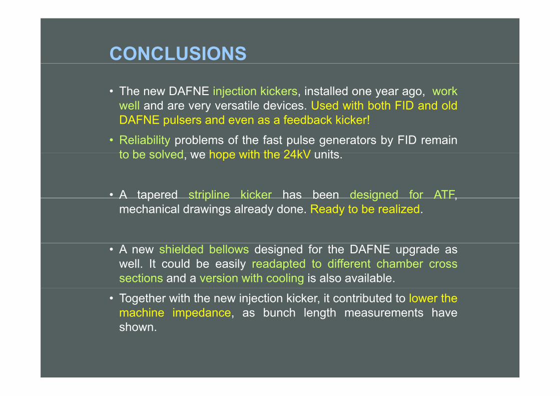
CONCLUSIONS
• The new DAFNE injection kickers, installed one year ago, workwell and are very versatile devices Used with both FID and oldwell and are very versatile devices. Used with both FID and oldDAFNE pulsers and even as a feedback kicker!
• Reliability problems of the fast pulse generators by FID remainto be solved we hope with the 24kV unitsto be solved, we hope with the 24kV units.
• A tapered stripline kicker has been designed for ATF,A tapered stripline kicker has been designed for ATF,mechanical drawings already done. Ready to be realized.
• A new shielded bellows designed for the DAFNE upgrade aswell. It could be easily readapted to different chamber crosssections and a version with cooling is also available.
• Together with the new injection kicker, it contributed to lower themachine impedance, as bunch length measurements haveshown.