fast laser micrometer with wide measuring range for high ... · model odc 1200 (axial model) odc...
TRANSCRIPT
More Precision.optoCONTROLNon-contact optical precision micrometers
Fast laser micrometer with wide measuring range for high-speed measurement of gap, segment, diameter, dimension, position in automation, production and quality control
2
- Excellent accuracy
- Extreme fast real time measurement
- Absolute non contact, wear-free measurement
- Solid state technology
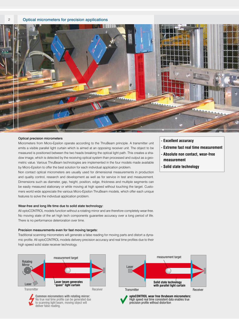
Optical precision micrometers
Micrometers from Micro-Epsilon operate according to the ThruBeam principle. A transmitter unit
emits a visible parallel light curtain which is aimed at an opposing receiver unit. The object to be
measured is positioned between the two heads breaking the optical light path. This creates a sha-
dow image, which is detected by the receiving optical system than processed and output as a geo-
metric value. Various ThruBeam technologies are implemented in the four models made available
by Micro-Epsilon to offer the best solution for each individual application problem.
Non contact optical micrometers are usually used for dimensional measurements in production
and quality control, research and development as well as for service in test and measurement.
Dimensions such as diameter, gap, height, position, edge, thickness and multiple segments can
be easily measured stationary or while moving at high speed without touching the target. Custo-
mers world wide appreciate the various Micro-Epsilon ThruBeam models, which offer each unique
features to solve the individual application problem.
Wear-free and long life time due to solid state technology:
All optoCONTROL models function without a rotating mirror and are therefore completely wear-free.
No moving state of the art high tech components guarantee accuracy over a long period of life.
There is no performance deterioration over time.
Precision measurements even for fast moving targets:
Traditional scanning micrometers will generate a false reading for moving parts and distort a dyna-
mic profile. All optoCONTROL models delivery precision accuracy and real time profiles due to their
high speed solid state receiver technology.
Transmitter Receiver
Laser
RotatingMirror
measurement target
Laser beam generates “quasi“ light curtain
Common micrometers with rotating mirror: No true real time profile can be generated due to scanning light beam, moving object will deliver false reading.
Transmitter Receiver
Laser
measurement target
Solid state technology with parallel light curtain
optoCONTROL wear free thrubeam micrometers:High speed real time consistent data enables trueprecision profile without distortion
Optical micrometers for precision applications
3
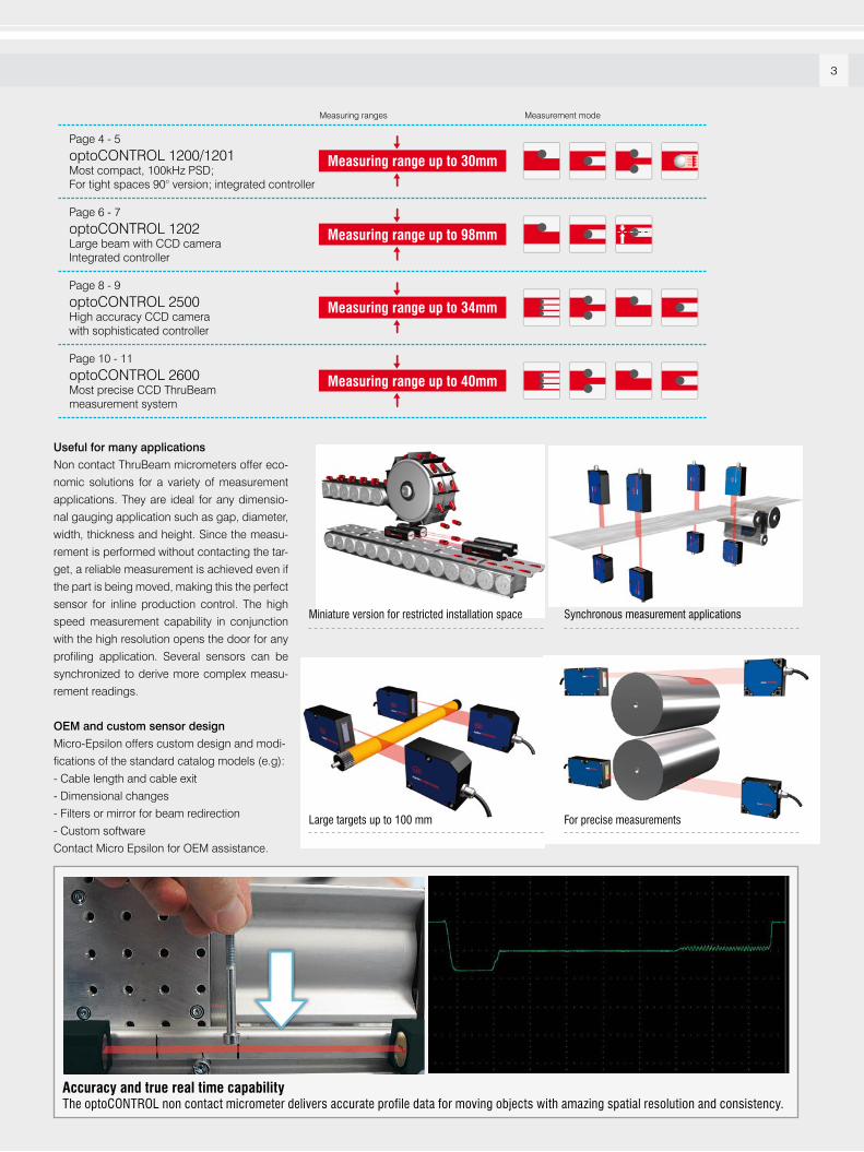
Useful for many applications
Non contact ThruBeam micrometers offer eco-
nomic solutions for a variety of measurement
applications. They are ideal for any dimensio-
nal gauging application such as gap, diameter,
width, thickness and height. Since the measu-
rement is performed without contacting the tar-
get, a reliable measurement is achieved even if
the part is being moved, making this the perfect
sensor for inline production control. The high
speed measurement capability in conjunction
with the high resolution opens the door for any
profiling application. Several sensors can be
synchronized to derive more complex measu-
rement readings.
OEM and custom sensor design
Micro-Epsilon offers custom design and modi-
fications of the standard catalog models (e.g):
- Cable length and cable exit
- Dimensional changes
- Filters or mirror for beam redirection
- Custom software
Contact Micro Epsilon for OEM assistance.
Page 4 - 5
optoCONTROL 1200/1201Most compact, 100kHz PSD;For tight spaces 90° version; integrated controller
Page 6 - 7
optoCONTROL 1202Large beam with CCD cameraIntegrated controller
Page 8 - 9
optoCONTROL 2500High accuracy CCD camerawith sophisticated controller
Page 10 - 11
optoCONTROL 2600Most precise CCD ThruBeammeasurement system
Measuring ranges Measurement mode
Measuring range up to 30mm
Measuring range up to 98mm
Measuring range up to 34mm
Measuring range up to 40mm
Accuracy and true real time capabilityThe optoCONTROL non contact micrometer delivers accurate profile data for moving objects with amazing spatial resolution and consistency.
Miniature version for restricted installation space Synchronous measurement applications
For precise measurementsLarge targets up to 100 mm
4
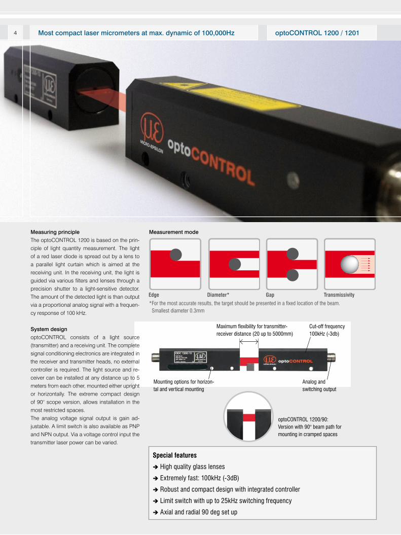
Measuring principle
The optoCONTROL 1200 is based on the prin-
ciple of light quantity measurement. The light
of a red laser diode is spread out by a lens to
a parallel light curtain which is aimed at the
receiving unit. In the receiving unit, the light is
guided via various filters and lenses through a
precision shutter to a light-sensitive detector.
The amount of the detected light is than output
via a proportional analog signal with a frequen-
cy response of 100 kHz.
System design
optoCONTROL consists of a light source
(transmitter) and a receiving unit. The complete
signal conditioning electronics are integrated in
the receiver and transmitter heads, no external
controller is required. The light source and re-
ceiver can be installed at any distance up to 5
meters from each other, mounted either upright
or horizontally. The extreme compact design
of 90° scope version, allows installation in the
most restricted spaces.
The analog voltage signal output is gain ad-
justable. A limit switch is also available as PNP
and NPN output. Via a voltage control input the
transmitter laser power can be varied.
Special features
High quality glass lenses
Extremely fast: 100kHz (-3dB)
Robust and compact design with integrated controller
Limit switch with up to 25kHz switching frequency
Axial and radial 90 deg set up
Maximum flexibility for transmitter-receiver distance (20 up to 5000mm)
Analog and switching output
Mounting options for horizon-tal and vertical mounting
optoCONTROL 1200/90: Version with 90° beam path for mounting in cramped spaces
Cut-off frequency 100kHz (-3db)
Measurement mode
Edge Diameter*
*For the most accurate results, the target should be presented in a fixed location of the beam. Smallest diameter 0.3mm
optoCONTROL 1200 / 1201Most compact laser micrometers at max. dynamic of 100,000Hz
Gap Transmissivity
5
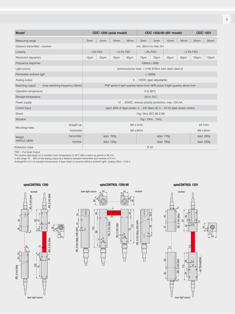
Model ODC 1200 (axial model) ODC 1200/90 (90° model) ODC 1201
Measuring range 2mm 5mm 10mm 16mm 2mm 5mm 10mm 16mm 20mm 30mm
Distance transmitter - receiver min. 20mm to max. 5m
Linearity <2% FSO <3.5% FSO <2% FSO <3.5% FSO
Resolution (dynamic) 10µm 25µm 50µm 80µm 10µm 25µm 50µm 80µm 100µm 150µm
Frequency response 100kHz (-3dB)
Light source semiconductor laser <1mW, 670nm (red, laser class 2)
Permissble ambient light ≤ 5000lx
Analog output 0 ... 10VDC (gain adjustable)
Switching output (max switching frequency 25kHz) PNP active if light quantity below limit; NPN active if light quantity above limit
Operation temperature 0 to 50°C
Storage temperature -20 to 70°C
Power supply 12 ... 32VDC, reverse polarity protection, max. 100 mA
Control input open: 66% of laser power; 5 ... 24V laser off; 0 ... 5V for laser power control
Shock 15g / 6ms (IEC 68-2-29)
Vibration 15g / 10Hz…1kHz
Mounting holesstraight up M4 x 5mm ø4.1mm
horizontal M5 x 8mm M4 x 6mm
Weight (without cable)
transmitter appr. 150g appr. 170g appr. 260g
receiver appr. 120g appr. 160g appr. 220g
Protection class IP 67
FSO = Full Scale OutputThe quoted data apply for a constant room temperature of 20°C after a warm-up period of 30 min,in the range 10 ... 90% of the analog output at a distance between transmitter and receiver of 0.5 m.Analogdrift 0.12 V at constant temperature; If laser beam is covered (without ambient light): analog offset <0.05 V
5
4
optoCONTROL 1200 optoCONTROL 1201
laser light source
receiver
laser light source
receiver
78
4
100
110
8745
2968
29
27
17
3.5
3.5278545
2025
10
3
3
16
57
M4,
5 m
m d
eep
M4,
5 m
m d
eep
ø4.1
thro
ughh
ole
M5,
8 m
m d
eep
M5,
8 m
m d
eep
1416
12
16
16
45
17
6037
45
M4,
6 m
m d
eep
M4,
6 m
m d
eep
28 34
16 17
12 1724 34
5
optoCONTROL 1200/90
laser light source receiver24 24
28
34
124
28 26
12
90
7811
0
32.5
45
25
28
16 16
12
3
4
4 3
16
16
12
M5,
8 m
m d
eep,
bot
h si
des
M4,
5 m
m d
eep
M4,
5 m
m d
eep
M5,
8 m
m d
eep,
bot
h si
des
6
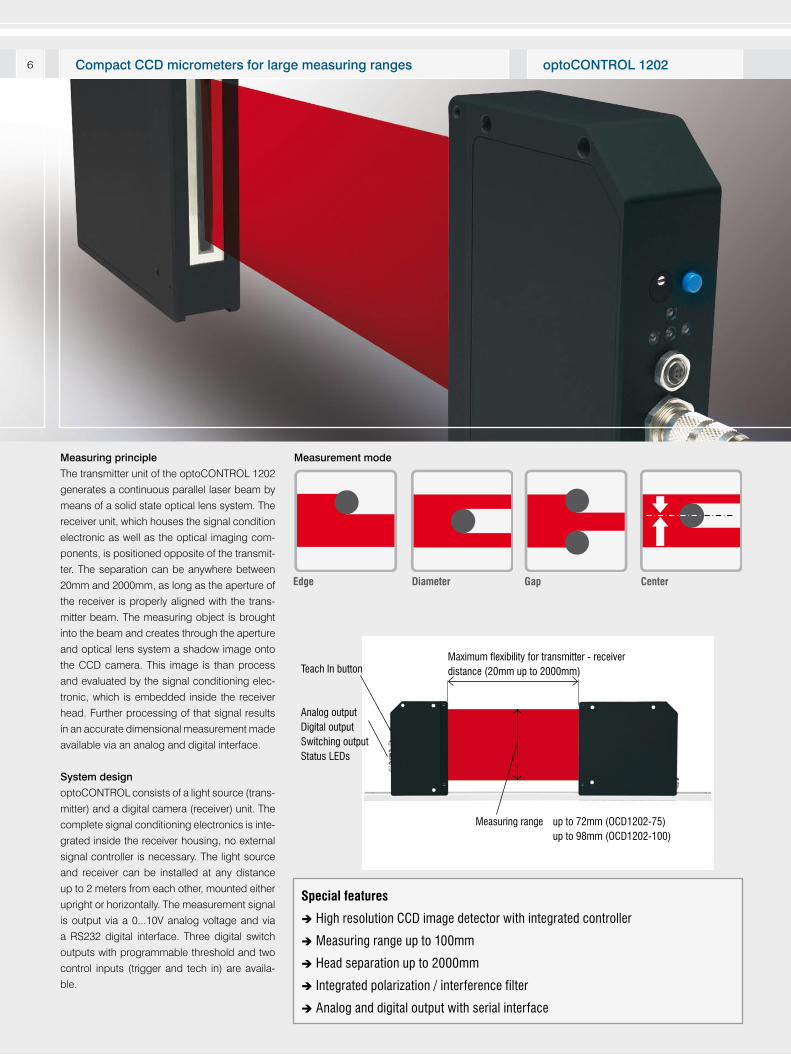
Measuring principle
The transmitter unit of the optoCONTROL 1202
generates a continuous parallel laser beam by
means of a solid state optical lens system. The
receiver unit, which houses the signal condition
electronic as well as the optical imaging com-
ponents, is positioned opposite of the transmit-
ter. The separation can be anywhere between
20mm and 2000mm, as long as the aperture of
the receiver is properly aligned with the trans-
mitter beam. The measuring object is brought
into the beam and creates through the aperture
and optical lens system a shadow image onto
the CCD camera. This image is than process
and evaluated by the signal conditioning elec-
tronic, which is embedded inside the receiver
head. Further processing of that signal results
in an accurate dimensional measurement made
available via an analog and digital interface.
System design
optoCONTROL consists of a light source (trans-
mitter) and a digital camera (receiver) unit. The
complete signal conditioning electronics is inte-
grated inside the receiver housing, no external
signal controller is necessary. The light source
and receiver can be installed at any distance
up to 2 meters from each other, mounted either
upright or horizontally. The measurement signal
is output via a 0...10V analog voltage and via
a RS232 digital interface. Three digital switch
outputs with programmable threshold and two
control inputs (trigger and tech in) are availa-
ble.
Maximum flexibility for transmitter - receiver distance (20mm up to 2000mm)
Analog outputDigital outputSwitching outputStatus LEDs
Teach In button
Measuring range up to 72mm (OCD1202-75) up to 98mm (OCD1202-100)
Measurement mode
DiameterEdge
optoCONTROL 1202Compact CCD micrometers for large measuring ranges
Special features
High resolution CCD image detector with integrated controller
Measuring range up to 100mm
Head separation up to 2000mm
Integrated polarization / interference filter
Analog and digital output with serial interface
Gap Center
7
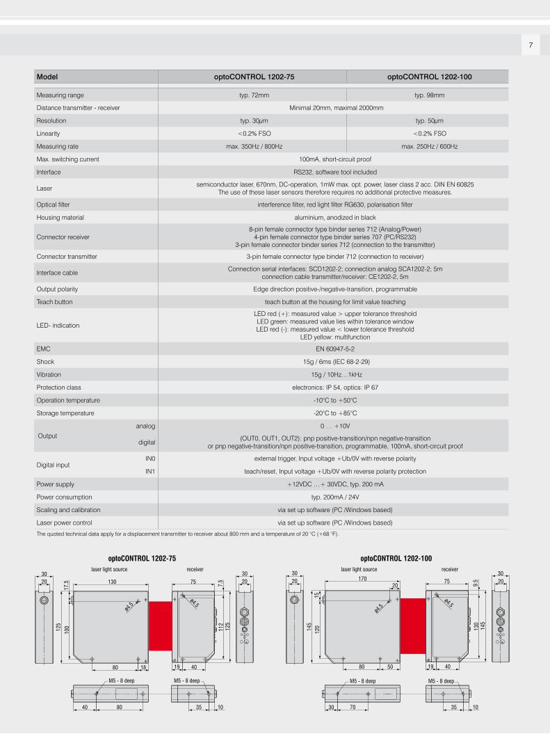
Model optoCONTROL 1202-75 optoCONTROL 1202-100
Measuring range typ. 72mm typ. 98mm
Distance transmitter - receiver Minimal 20mm, maximal 2000mm
Resolution typ. 30µm typ. 50µm
Linearity <0.2% FSO <0.2% FSO
Measuring rate max. 350Hz / 800Hz max. 250Hz / 600Hz
Max. switching current 100mA, short-circuit proof
Interface RS232, software tool included
Lasersemiconductor laser, 670nm, DC-operation, 1mW max. opt. power, laser class 2 acc. DIN EN 60825
The use of these laser sensors therefore requires no additional protective measures.
Optical filter interference filter, red light filter RG630, polarisation filter
Housing material aluminium, anodized in black
Connector receiver8-pin female connector type binder series 712 (Analog/Power)
4-pin female connector type binder series 707 (PC/RS232)3-pin female connector binder series 712 (connection to the transmitter)
Connector transmitter 3-pin female connector type binder 712 (connection to receiver)
Interface cableConnection serial interfaces: SCD1202-2; connection analog SCA1202-2; 5m
connection cable transmitter/receiver: CE1202-2, 5m
Output polarity Edge direction positive-/negative-transition, programmable
Teach button teach button at the housing for limit value teaching
LED- indication
LED red (+): measured value > upper tolerance thresholdLED green: measured value lies within tolerance windowLED red (-): measured value < lower tolerance threshold
LED yellow: multifunction
EMC EN 60947-5-2
Shock 15g / 6ms (IEC 68-2-29)
Vibration 15g / 10Hz…1kHz
Protection class electronics: IP 54, optics: IP 67
Operation temperature -10°C to +50°C
Storage temperature -20°C to +85°C
Output
analog 0 … +10V
digital(OUT0, OUT1, OUT2): pnp positive-transition/npn negative-transition
or pnp negative-transition/npn positive-transition, programmable, 100mA, short-circuit proof
Digital inputIN0 external trigger, Input voltage +Ub/0V with reverse polarity
IN1 teach/reset, Input voltage +Ub/0V with reverse polarity protection
Power supply +12VDC …+ 30VDC, typ. 200 mA
Power consumption typ. 200mA / 24V
Scaling and calibration via set up software (PC /Windows based)
Laser power control via set up software (PC /Windows based)
The quoted technical data apply for a displacement transmitter to receiver about 800 mm and a temperature of 20 °C (+68 °F).
170
ø4.5
1512
0145
50
20
80
M5 - 8 deep
30 70
3020 75
3020
ø4.5
9.5
4019
M5 - 8 deep
35
optoCONTROL 1202-100
130
ø4.5
1880
M5 - 8 deep
40 80
3020
3020
optoCONTROL 1202-75 laser light source receiver laser light source receiver
75
ø4.5
7.5
125
4019
M5 - 8 deep
10 1035
112
17.5
10012
5
130
145
8
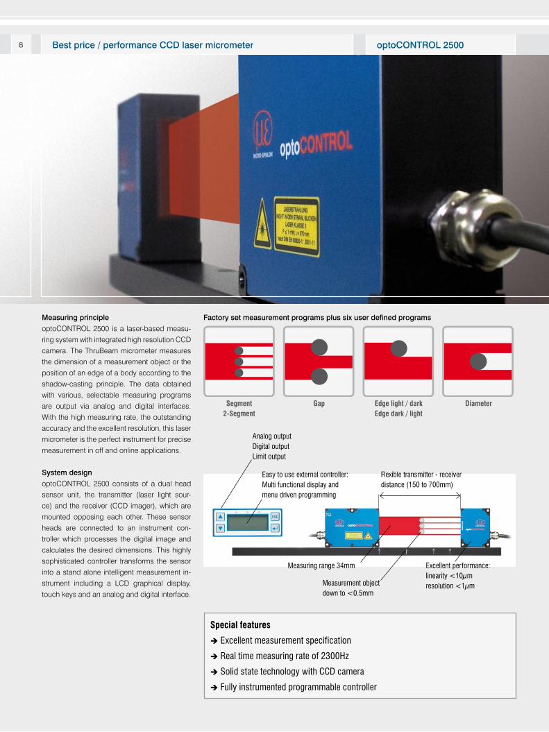
Measuring principle
optoCONTROL 2500 is a laser-based measu-
ring system with integrated high resolution CCD
camera. The ThruBeam micrometer measures
the dimension of a measurement object or the
position of an edge of a body according to the
shadow-casting principle. The data obtained
with various, selectable measuring programs
are output via analog and digital interfaces.
With the high measuring rate, the outstanding
accuracy and the excellent resolution, this laser
micrometer is the perfect instrument for precise
measurement in off and online applications.
System design
optoCONTROL 2500 consists of a dual head
sensor unit, the transmitter (laser light sour-
ce) and the receiver (CCD imager), which are
mounted opposing each other. These sensor
heads are connected to an instrument con-
troller which processes the digital image and
calculates the desired dimensions. This highly
sophisticated controller transforms the sensor
into a stand alone intelligent measurement in-
strument including a LCD graphical display,
touch keys and an analog and digital interface.
Measuring range 34mm
Measurement object down to <0.5mm
Easy to use external controller:Multi functional display and menu driven programming
Analog outputDigital outputLimit output
Flexible transmitter - receiverdistance (150 to 700mm)
Excellent performance:linearity <10μmresolution <1μm
Special features
Excellent measurement specification
Real time measuring rate of 2300Hz
Solid state technology with CCD camera
Fully instrumented programmable controller
Factory set measurement programs plus six user defined programs
Segment2-Segment
Gap Edge light / darkEdge dark / light
Diameter
optoCONTROL 2500Best price / performance CCD laser micrometer
9
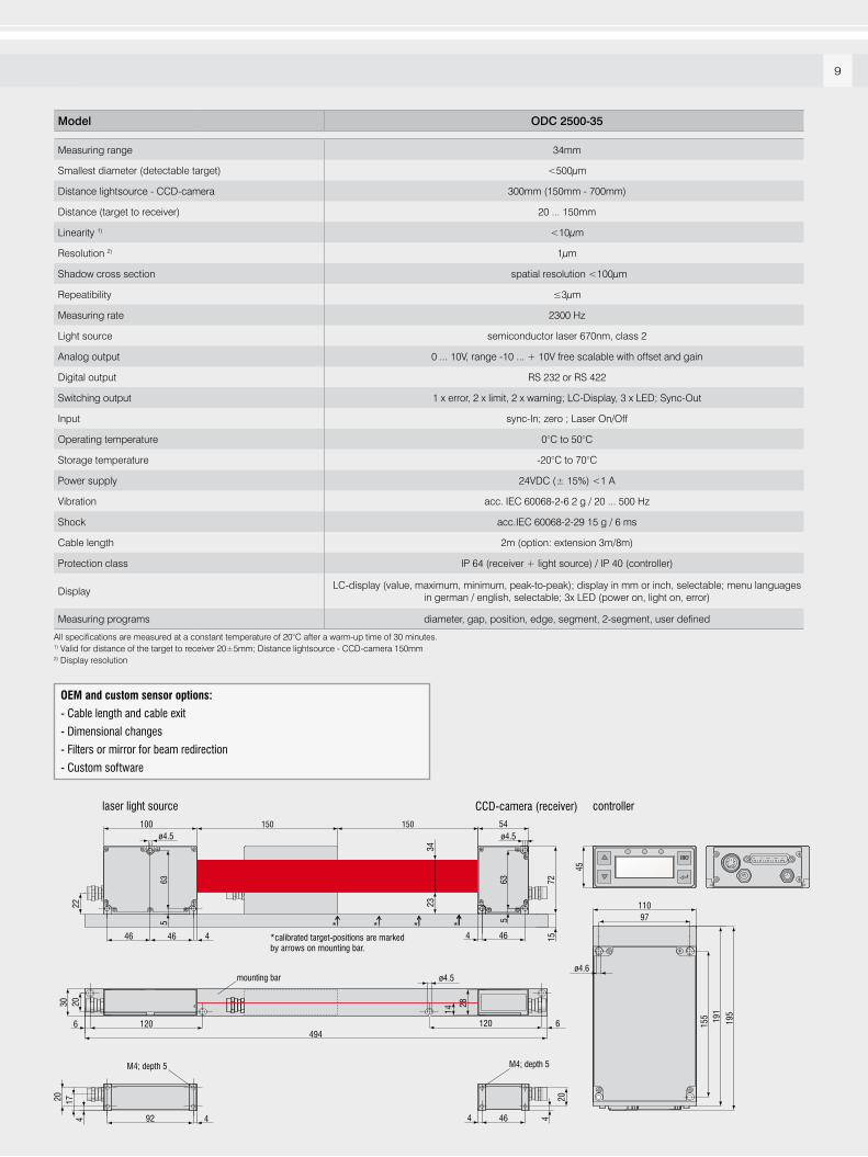
Model ODC 2500-35
Measuring range 34mm
Smallest diameter (detectable target) <500µm
Distance lightsource - CCD-camera 300mm (150mm - 700mm)
Distance (target to receiver) 20 ... 150mm
Linearity 1) <10µm
Resolution 2) 1µm
Shadow cross section spatial resolution <100µm
Repeatibility ≤3µm
Measuring rate 2300 Hz
Light source semiconductor laser 670nm, class 2
Analog output 0 ... 10V, range -10 ... + 10V free scalable with offset and gain
Digital output RS 232 or RS 422
Switching output 1 x error, 2 x limit, 2 x warning; LC-Display, 3 x LED; Sync-Out
Input sync-In; zero ; Laser On/Off
Operating temperature 0°C to 50°C
Storage temperature -20°C to 70°C
Power supply 24VDC (± 15%) <1 A
Vibration acc. IEC 60068-2-6 2 g / 20 ... 500 Hz
Shock acc.IEC 60068-2-29 15 g / 6 ms
Cable length 2m (option: extension 3m/8m)
Protection class IP 64 (receiver + light source) / IP 40 (controller)
DisplayLC-display (value, maximum, minimum, peak-to-peak); display in mm or inch, selectable; menu languages
in german / english, selectable; 3x LED (power on, light on, error)
Measuring programs diameter, gap, position, edge, segment, 2-segment, user defined
All specifications are measured at a constant temperature of 20°C after a warm-up time of 30 minutes.1) Valid for distance of the target to receiver 20±5mm; Distance lightsource - CCD-camera 150mm2) Display resolution
OEM and custom sensor options:
- Cable length and cable exit
- Dimensional changes
- Filters or mirror for beam redirection
- Custom software
laser light source CCD-camera (receiver)
17
924
20
4 464
20
4
M4; depth 5 M4; depth 5
mounting bar
120 120
2030
4946 6
ø4.5
110
191
195
155
97
ø4.6
45
controller
22
54100
46 46
ø4.5
635
46** * *
*calibrated target-positions are markedby arrows on mounting bar.
635
44
ø4.5150150
15
3423
72
14
28
10
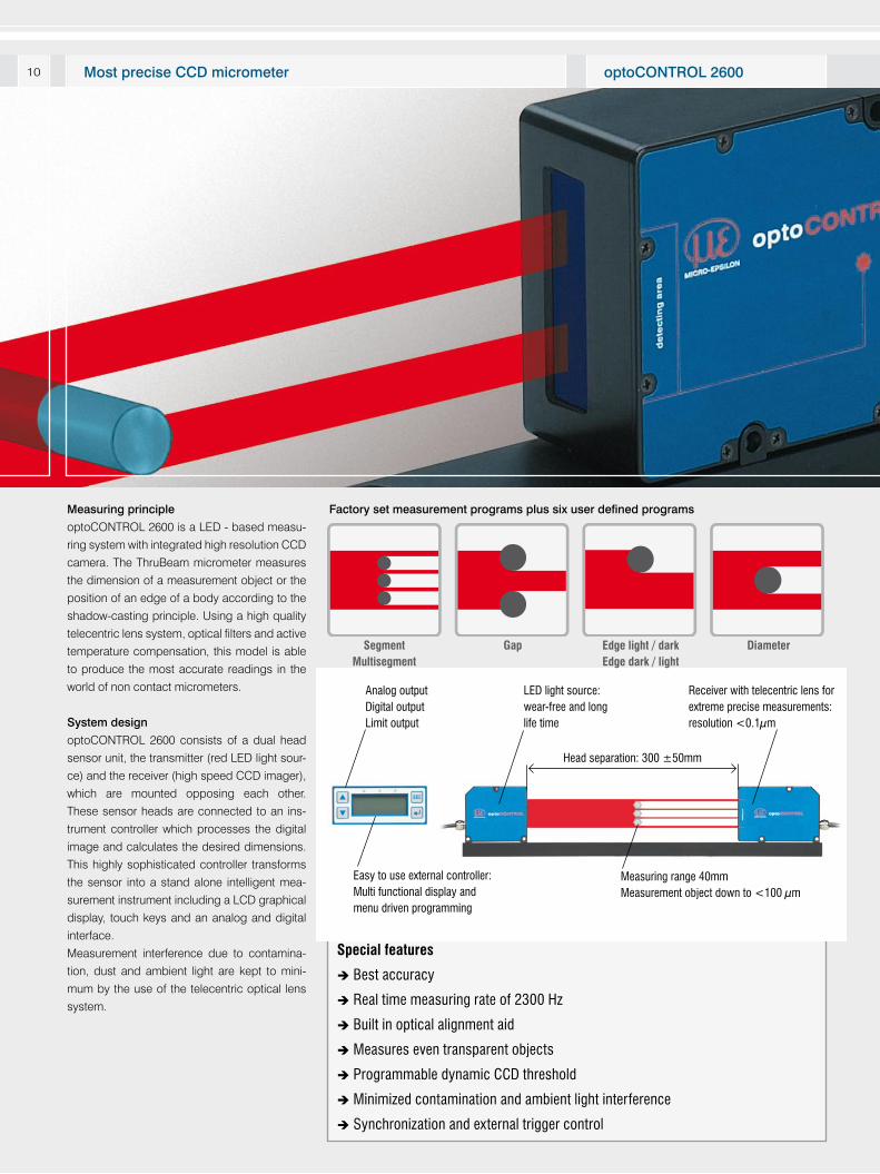
Measuring principle
optoCONTROL 2600 is a LED - based measu-
ring system with integrated high resolution CCD
camera. The ThruBeam micrometer measures
the dimension of a measurement object or the
position of an edge of a body according to the
shadow-casting principle. Using a high quality
telecentric lens system, optical filters and active
temperature compensation, this model is able
to produce the most accurate readings in the
world of non contact micrometers.
System design
optoCONTROL 2600 consists of a dual head
sensor unit, the transmitter (red LED light sour-
ce) and the receiver (high speed CCD imager),
which are mounted opposing each other.
These sensor heads are connected to an ins-
trument controller which processes the digital
image and calculates the desired dimensions.
This highly sophisticated controller transforms
the sensor into a stand alone intelligent mea-
surement instrument including a LCD graphical
display, touch keys and an analog and digital
interface.
Measurement interference due to contamina-
tion, dust and ambient light are kept to mini-
mum by the use of the telecentric optical lens
system.
Special features
Best accuracy
Real time measuring rate of 2300 Hz
Built in optical alignment aid
Measures even transparent objects
Programmable dynamic CCD threshold
Minimized contamination and ambient light interference
Synchronization and external trigger control
Measuring range 40mmMeasurement object down to <100 μm
LED light source:wear-free and long life time
Receiver with telecentric lens for extreme precise measurements:resolution <0.1μm
Head separation: 300 ±50mm
Factory set measurement programs plus six user defined programs
Segment Multisegment
Gap Edge light / darkEdge dark / light
Diameter
Easy to use external controller:Multi functional display and menu driven programming
Analog outputDigital outputLimit output
optoCONTROL 2600Most precise CCD micrometer
11
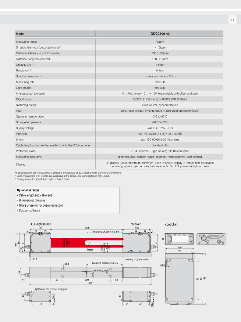
Model ODC2600-40
Measuring range 40mm
Smallest diameter (detectable target) <100µm
Distance lightsource - CCD-camera 300 (±50)mm
Distance (target to receiver) 150 (±5)mm
Linearity (3s) 1) <±1µm
Resolution 2) 0.1µm
Shadow cross section spatial resolution <20µm
Measuring rate 2300 Hz
Light source red LED
Analog output (voltage) 0 ... 10V, range -10 ... + 10V free scalable with offset and gain
Digital output RS232 (115.2kBaud) or RS422 (691.2kBaud)
Switching output error, 4x limit, synchronisation
Input zero; reset; trigger; synchronisation; light on/off (programmable)
Operation temperature 0°C to 50°C
Storage temperature -20°C to 70°C
Supply voltage 24VDC (±15%), <1 A
Vibration acc. IEC 60068-2-6 2g / 20 ... 500Hz
Shock acc. IEC 60068-2-29 15g / 6ms
Cable length (controller-transmitter / controller-CCD-camera) Standard: 2m
Protection class IP 64 (receiver + light source) / IP 40 (controller)
Measuring programs diameter, gap, position ,edge, segment, multi segment, user defined
DisplayLC-display (value, maximum, minimum, peak-to-peak); display in mm or inch, selectable;
menu languages in german / english, selectable; 3x LED (power on, light on, error)
All specifications are measured at a constant temperature of 20°C after a warm-up time of 30 minutes.1) Edge measurement at 2.3kHz, no averaging at the target, operating distance 150 ±5mm. 2) Display resolution (resolution digital output 0.6µm)
mid
of
mea
surin
g ra
nge
40.5m
easu
ring
rang
e40
24
87
ø4.8
300measuring distance 150 ±5
measuring distance 150 ±5
116
71
39393939
71
44
8010
0
target
LED-lightsource receiver
mouting rail (detachable)
measuring level
12
45
200
30
ø6.6
50 50510
26.5
578 7834
35 35
lightsource and receiver are keyed
M4x
5
M4x
5
110
191
195
155
97
ø4.6
45
controller
Optional versions
- Cable length and cable exit
- Dimensional changes
- Filters or mirror for beam redirection
- Custom software
Mod
ifica
tions
rese
rvre
d / Y
9766
284-
A01
0119
DG
O
Accessories for optoCONTROL 2500/2600
2420057 CSP2008 Universal controller for several signals
2213017 IF2008 PCI interface card RS422
2901057 CE1800-3 Sensor cable extension for camera, 3m
2901118 CE2500-3 Sensor cable extension for light source, 3m
2901058 CE1800-8 Sensor cable extension for camera, 8m
2901119 CE2500-8 Sensor cable extension for light source, 8m
2901120 SCA2500-3 3 Signal output cable, analog, 3m
2901121 SCD2500-3/3/RS232
Output cable with RS422, 3 and 10m,
for connection to IF2008
2213014 USB Converter RS422 to USB
2901122 SCD2500-3/10/RS422
Signal output cable 3m / RS422 10m
2901123 PC2500-3 Power supply cable 3m
2901124 PC2500-10 Power supply cable 10m
2901504 SCD2500-3/CSP Power supply and output cable 3m,
for connection to CSP2008
2901505 SCD2500-10/CSP Power supply and output cable 10m,
for connection to CSP2008
Accessories for optoCONTROL 1200/1201/1202
Art. No. Modell
2901260 PC1200-5 Power supply and signal cable 5m, straight
connector, for light source and receiver unit
2901261 PC1200/90-5 Power supply and signal cable 5m, 90 degree
connector, for light source and receiver unit
2420019 PS2010 Power supply for DIN rail mounting, input
230VAC, output 24V DC/2.5 A
2901497 CE1202-2 Connecting cable transmitter-receiver, 2m
2901482 CE1202-5 Connecting cable transmitter-receiver, 5m
2901371 SCD1202-2 Digital output cable, 2m, for connection to a
RS232 port
2901509 SCD1202-5 Digital output cable, 5m, for connection to a
RS232 port
2901373 SCA1202-2 Power supply and analog output cable, 2m
2901510 SCA1202-5 Power supply and analog output cable, 5m
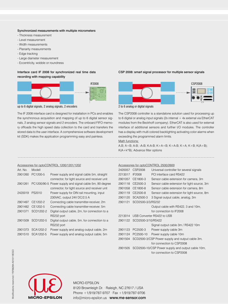
Synchronized measurements with multiple micrometers
- Thickness measurement
- Level measurement
- Width measurements
- Planarity measurements
- Edge tracking
- Large diameter measurement
- Eccentricity, wobble or roundness
CSP2008
2 to 6 analog or digital signalsup to 6 digital signals, 2 analog signals, 2 encoders
The CSP2008 controller is a standalone solution used for processing up
to 6 digital or analog input signals (2x internal + 4x external via EtherCAT
modules from the Beckhoff company). EtherCAT is also used for external
interface of additional sensors and further I/O modules. The controller
has a display with multi colored backlighting activating color alarms when
exceeding the programmed alarm limits.
Math functions:
A,B; A+B; A-B; -A-B; K-A-B; K+A+B; K+A-B; K+A; K+B; K(A+B);
K(A+k*B); Advance filter options
CSP 2008: smart signal processor for multiple sensor signalsInterface card IF 2008 for synchronized real time data
recording with mapping capability
The IF 2008 interface card is designed for installation in PCs and enables
the synchronous acquisition and mapping of up to 6 digital sensor sig-
nals, 2 analog sensor signals and 2 encoders. The onboard FIFO memo-
ry offloads the high speed data collection to the card and transfers the
stored data to the user interface. A comprehensive software development
kit (SDK) makes the application programming easy and painless.
IF2008
MICRO-EPSILON 8120 Brownleigh Dr. · Raleigh, NC 27617 / USAPhone +1/919/787-9707 · Fax +1/919/[email protected] · www.me-sensor.com