fast track precast concrete pavement rehabilitation pilot
TRANSCRIPT

Fast Track Precast Concrete Pavement Rehabilitation Pilot Project
Susanne Chan, M.A.Sc, P.Eng.
Pavement Design Engineer,
Ministry of Transportation Ontario
Warren Lee, M.A.Sc, P.Eng. Pavement Design Engineer,
Ministry of Transportation Ontario
Becca Lane, P.Eng. Manager, Materials Engineering Research office,
Ministry of Transportation
Tom Kazmierowski, P.Eng Senior Consultant, Pavement and Materials Engineering,
Golder Associates Ltd.
Paper prepared for presentation at SES - Innovations in Pavement Management, Engineering and Technologies Session
of the 2017 Conference of the Transportation Association of Canada
St. John’s, NL

1
ABSTRACT
As Ontario’s highway network expands and is subjected to increasing traffic volumes, the
Ministry of Transportation Ontario (MTO) is challenged to look for new and innovative solutions
to preserve and maintain the highway system. The ministry has identified a few high truck traffic
sections having Average Annual Daily Truck Traffic (AADTT) greater than 25,000 that are
experiencing progressively early rutting failure, and a few thick asphalt pavements experiencing
full depth cracking. To reduce impacts to the travelling public, these high volume highways
require all major maintenance and rehabilitation works to be performed under tight nightly
construction closures. The typical rehabilitation holding treatment of mill and overlay at these
locations may last only 3 to 5 years, rather than the expected 8 to 12 years, before the rutting
and cracking return. Based on the progressively shorter lifecycles of this holding strategy, the
ministry is investigating a potentially more life cycle friendly option of using overnight precast
concrete mill and inlay techniques to mitigate this progressive rutting and cracking challenge.
This paper describes an MTO pilot project using precast concrete slabs to rehabilitate a deep
strength flexible pavement. The paper discusses how three different slab support systems were
evaluated based on factors such as load transfer and ease of construction; the challenges of
construction staging based on an 8 hours work window, with adaptations of horizontal and
longitudinal joint details for the anticipated temporary and permanent works; lessons learned
and next steps. Furthermore, the paper presents post construction roughness, load transfer
efficiency and friction results of the tined longitudinal texture on the precast slabs.

2
1. INTRODUCTION
The Ministry of Transportation Ontario (MTO) is challenged to look at innovations to preserve
and maintain the highway system. Several high volume flexible highways are experiencing
progressive early rutting failure with full depth cracking issues. The typical holding strategy used
is mill and overlay with HMA, which lasts only 3 to 5 years, rather than the expected 8 to 12
years, before the rutting and cracking issues return. To reduce the construction impact to the
travelling public, these locations require all maintenance and rehabilitation work be performed
under tight nightly closures. With this operational constraint, MTO is interested in studying a
new method for rehabilitation that has a longer service life but can still be installed during
overnight construction windows.
2. BACKGROUND
The ministry investigated a potentially more life cycle friendly use of precast concrete inlay on
deep strength flexible pavement to mitigate the progressive rutting and cracking performance.
The idea was inspired by the use of precast concrete slabs to repair existing concrete on some
high volume composite pavements in the Toronto area.
In 2004, MTO carried out its first trial project to evaluate construction techniques for precast
concrete slab repairs on concrete/composite pavements. The initial trial was carried out on
Highway 427, in Toronto (1). Based on MTO experience with this trial contract, a specification
was developed and additional precast repair work carried out through the years. MTO has
successful experience on the use of precast concrete repairs on concrete pavement, and this
experience inspired the use of precast concrete slab to repair flexible pavement.
3. PROJECT LOCATION
The pilot project is located on the northbound section of Highway 400 between the intersections
of Highways 88 (to the south) and 89 (to the north). The 2013 average annual daily traffic
(AADT) in both directions was estimated to be 87,300. Figure 1 below shows the approximate
location of the pilot project.

3
Figure 1: Pilot Project Location on Highway 400 and between Highway 88 and 89
(Source: Google Map)
4. METHODOLOGY
The pilot project used precast concrete slabs based on the Fort Miller Super-Slab® Method. The
hot mix asphalt (HMA) in lane 3 (outside lane) was milled partial depth and the precast slabs
were placed within the milled-out recess. Three slab support methods or systems were
employed for this pilot study: 1) Asphalt Supported Slab; 2) Graded Supported Slab; and 3)
Grout Supported Slab. Also, long term monitoring instrumentation was installed as part of the
work in partnership with University of Waterloo, Center for Pavement and Transportation
Technology (CPATT).
4.1 Precast Concrete Slab Fabrication
There were a total of 22 reinforced precast slabs required for this contract and they were
fabricated in late August to early September 2016 at the Armtec production facility located in
Mitchell, Ontario. To ensure good friction, sufficient micro and macro texture on the precast
surface was mandatory. Several trials were performed on the precast concrete surface to
produce an acceptable surface texture. The final surface texture was a broom finish, followed by
longitudinal tining. Care was exercised to ensure a constant pressure was applied during the
brooming and longitudinal tining processes to provide the required texture. Figure 2 below
shows the precast concrete slab production.

4
Figure 2: Precast Slab Production
4.2 Design Considerations
Cores of the site location were taken to ensure sufficient asphalt depth was available to provide
uniform support of the precast slabs. Three cores indicated the northbound lane 3 asphalt
thicknesses were 355, 375 and 375 mm. With a precast concrete slab of 205 mm, there was
sufficient asphalt thickness to mill down and place the precast concrete inlay slab, with about
150 mm asphalt remaining as the base support. Figure 3 is the schematic of the precast
concrete slab inlay repair of the flexible pavement.
Figure 3: Precast Concrete Slab Repair Rehabilitation on Asphalt Pavement
5
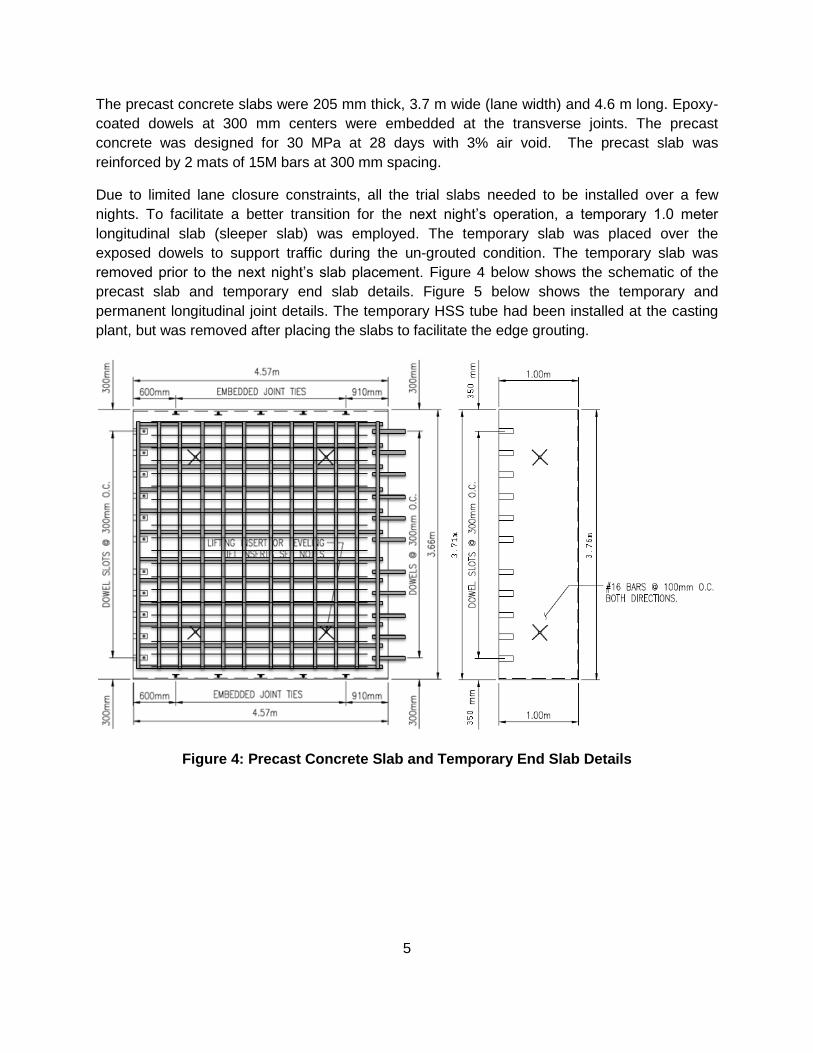
The precast concrete slabs were 205 mm thick, 3.7 m wide (lane width) and 4.6 m long. Epoxy-
coated dowels at 300 mm centers were embedded at the transverse joints. The precast
concrete was designed for 30 MPa at 28 days with 3% air void. The precast slab was
reinforced by 2 mats of 15M bars at 300 mm spacing.
Due to limited lane closure constraints, all the trial slabs needed to be installed over a few
nights. To facilitate a better transition for the next night’s operation, a temporary 1.0 meter
longitudinal slab (sleeper slab) was employed. The temporary slab was placed over the
exposed dowels to support traffic during the un-grouted condition. The temporary slab was
removed prior to the next night’s slab placement. Figure 4 below shows the schematic of the
precast slab and temporary end slab details. Figure 5 below shows the temporary and
permanent longitudinal joint details. The temporary HSS tube had been installed at the casting
plant, but was removed after placing the slabs to facilitate the edge grouting.
Figure 4: Precast Concrete Slab and Temporary End Slab Details

6
Figure 5: Temporary and Permanent Longitudinal Joint Details
5. CONSTRUCTION
There were a total of 22 precast concrete slabs with three support methods used in this pilot
study. The contractor planned to install 7 to 8 slabs for each of the three methods in three
consecutive nights. Due to the tight timeline, the nightly activity needed to be well planned in
advance to avoid any possible construction delay. Figure 6 below is the nightly construction
activity schedule.
Figure 6: Precast Concrete Trial Activity Schedule

7
The final site location and layout of the three installation methods was decided upon discussion
with MTO, CPATT, the Consultant and the Contractor. Figure 7 below shows the planned layout
of the installation method.
Figure 7: Site Layout of the Three Support Methods
The Contractor began the site layout on September 15th, 2016, followed by saw-cutting of the
perimeter of the asphalt area to be milled on September 19th, 2016.
5.1 Option 1: Asphalt Supported Slab Method
The first night of slab installation commenced on Sept 20th, 2016 with the Asphalt Supported
Slab method. This method requires the precast concrete slabs to be supported directly onto a
precisely milled asphalt base and then grouted in place the following night.
The milling machine was a Wirtgen Model W120 CFI, with a 1.2 m-wide milling head. Three
passes of the milling unit were carried out to mill to the required width. (Figure 8)
Figure 8: Wirtgen Milling Machine

8
Since the Asphalt Supported Slab method requires a precise milling depth of the asphalt
(tolerance of ± 3 mm), the Fort Miller grade check apparatus was adopted to ensure milled
surface tolerances were achieved prior to placing the slab (Figure 9). (2)
Figure 9: Fort Miller Grade Checker Apparatus
After first slab placement, the surface deferential between the adjacent lane surface and the
precast slab surface was found to be approximately 9 mm. This was corrected by slab removal
and additional milling of 12 mm based on the readings from Fort Miller’s grade checker. The
surface differential between adjacent slabs was found to be small (within ± 3 mm tolerance as
required in the specification) for the remainder of the slabs. The CPATT instrumentation was
installed beneath the fourth and eighth Asphalt Supported Slab. Figure 10 shows the installation
of the precast concrete slab.

9
Figure 10: Precast Concrete Slab Installation (Asphalt Supported Slab)
A total of 8 asphalt supported slabs were placed in approximately 1 hour 10 minutes, for an
average placement time of approximately 9 minutes/slab. Following placement of the 8 slabs,
the temporary end slab was then installed (Figure 11). The fast-setting bedding grouting, dowel
grout and edge grout for longitudinal joints were applied the next night (Figure 12).
Figure 11: Asphalt Supported Slab and Temporary End Slab

10
Figure 12: Pumping the Dowel Grout
5.2 Option 2: Grade Supported Slab Method
The Grade Supported Slabs were placed on September 21st, 2016. This method involved milling
of the asphalt, followed by placement, grading, and wetting of the cement-treated bedding
material (CTBM) prior to placing the precast concrete slab on top.
The same milling machine (Figure 8) and Fort Miller Grade Checker (Figure 9) were used as in
the Asphalt Supported Slab method. The CPATT instrumentation was installed underneath the
second and fourth slabs prior to placement of the CTBM. The CTBM was graded using a
manual leveling screed and compacted using the plate tamper to the correct elevation. The
material was wetted to begin hydration and the slabs were placed directly on this bedding layer
(Figure 13).
Figure 13: Compaction of the CTBM Grade Supported Slab Method
A total of 7 grade supported slabs were placed in approximately 90 minutes, for an average of
approximately 13 minutes/slab. Following placement of the 7 slabs, the temporary end slab was
then installed. The edge grout for longitudinal joints was applied the next night.

11
5.3 Option 3: Grout Supported Slab Method
The Grout Supported Slabs were placed on September 22nd, 2016. This method used built-in
leveling screws (or jacking bolts) which rested on the milled asphalt surface. These leveling
screws have the capability of adjusting the level of the concrete slab to the required elevation,
Quick setting bedding grout was then injected to support the slab.
The same milling machine (Figure 8) used for the Asphalt Supported Slab method was used to
remove the asphalt for this support method, and the CPATT instrumentation was installed prior
to slab placement. Three grout mixers were used to produce the increased amount of bedding
grout required to fill the void beneath the Grout Supported Slab. Figure 14 below shows the
adjustment of the levelling screw for this method.
Figure 14: Grout Supported Slab Levelling Screw and Adjustment
A total of 7 grout supported slabs were placed in approximately 85 minutes, for an average
placement time of approximately 12 minutes/slab.
5.4 Summary of Construction
Table 1 below shows the summary of the construction timing and usage of bedding grout for
each installation method.
Table 1: Summary of Construction Activity
Asphalt Supported
Grade Supported
Grout Supported
Date Installed Sept 20, 2016 Sept 21, 2016 Sept 22, 2016
Milling time (min) 215 120 75
Slab Placement Time (min) 70 90 85
Time per Slab (min/slab) 9 13 12
Bedding Grout per slab (bags) 12 4 14

12
6. POST-CONSTRUCTION DATA ANALYSIS
The post construction data collected right after construction included Falling Weight
Deflectometer (FWD), friction and roughness testing. Out of the 22 slabs placed, only one slab
did not meet the 3 mm tolerance and needed to be diamond ground as per the specification.
6.1 Falling Weight Deflectometer
MTO retained a consultant to carry out the load transfer testing using the FWD at the transverse
joints of the precast slabs. The testing was completed on October 6 and 7, 2016 according to
ministry’s requirement. (3) A total of 23 joints were tested for load transfer efficiency (LTE %)
and void detection. Below is the summary table showing the FWD testing results.
Table 2: FWD Testing Results Summary
Joint Station
Outer Wheelpath (OWP) Inner Wheelpath (IWP)
Approach (LTE %)
Leave (LTE %) Void
Approach (LTE %)
Leave (LTE %) Void
1 17+550 67.8 66.7 No 66.6 87.8 No
2 17+555 73.3 84.4 No 81 74.3 No
3 17+560 84.3 81.7 No 81.3 81.4 No
4 17+565 85.3 83.4 No 79.5 75.7 No
5 17+570 81.5 81.6 No 83.6 85.1 No
6 17+575 78.1 79.3 No 79.1 77.6 No
7 17+580 86 82.2 No 80.2 78 No
8 17+585 77.7 79.9 No 78 80.3 No
9 17+590 78.8 85.4 No 75.7 77.7 No
10 17+595 76.7 79.8 No 80.2 83.1 No
11 17+600 77.1 77.5 No 83.8 76.3 No
12 17+605 77.5 81 No 82.3 79.3 No
13 17+610 80.8 79.2 No 84.8 82.9 No
14 17+615 80 82.8 No 81.9 82.2 No
15 17+620 78.8 83.5 No 83.6 78.4 No
16 17+625 83.3 82.3 No 82.6 76.3 No
17 17+630 80.4 79.5 No 79.9 77.7 No
18 17+635 86.8 84 No 84 83.4 No
19 17+640 87.2 83.3 No 79.8 77.5 No
20 17+645 89.3 87.2 No 83.7 80.9 No
21 17+650 88 82.6 No 83.4 77.9 No
22 17+655 89 81.4 No 82.5 82 No
23 17+660 90 78.2 No 54.5 50.9 No

13
As a general practice, the load transfer is considered to be acceptable when LTE is greater than
70%. The average LTE for all 23 joints was 80.3%, which indicates a relatively good load
transfer for this precast concrete slab placement. Breaking it down to the different installation
methods, joint 2 to 9 for asphalt supported method achieved an average 80.4% LTE; joint 10 to
16 for grade supported method averaged 80.6% LTE; and joint 17 to 22 for grout supported
method averaged 83% LTE. The first and last joints were not counted in the breakdown
because those joints were adjacent to the asphalt with no load transfer device installed. Overall,
all three methods of support provided good load transfer efficiency and no voids were
encountered, with the grout supported method providing slightly better LTE when compared to
the 2 other support methods.
6.2 Roughness
Roughness was assessed by measuring the International Roughness Index (IRI) using the
Automated Road Analyzer (ARAN). IRI is a roughness index with 0 mm/m representing a
perfectly smooth pavement, and as the IRI increases, the measure represents a less
smooth/rougher pavement. Typical IRI values for a concrete surface are higher than a HMA
surface because the longitudinal profile measurement will capture the tining of the concrete
surface resulting in a higher reading. The average IRI summarized in 10 m intervals for all the
precast concrete inlay slabs was 2.14 mm/m and for the adjacent asphalt pavement was 0.76
mm/m.
Table 3 below is the breakdown of the IRI result for each installation method, and it appears
Grout Supported Slab method was smoother when compared to the other 2 methods.
Table 3: Summary of IRI Result
Asphalt Supported Grade Supported Grout Supported
IRI (mm/m) 2.39 2.57 1.81
6.3 Friction
Frictional resistance testing was performed using a locked wheel Friction Tester unit per ASTM
E-274 with ASTM E 501 standard ribbed tire. The tined longitudinal texture provided friction
numbers in excess of FN30.
7. LESSONS LEARNED
Precast concrete slabs require a uniform base for support. The challenge of this pilot project
was to precisely mill the asphalt to a specific depth and provide a uniform surface for the
precast slab to sit on. Thus, precise surface measurement and milling head control is critical for
the success of this process.
Base on this pilot experience, it was found that milling slightly deeper is better than under
milling. The specialized milling machine was able to meet the specified grade requirement of ± 3
mm and provide a uniform milled surface texture.

14
Manual chipping of localized high spots and chipping of the asphalt rounding from the milling
head delayed installation by about 1 hour. Therefore, it is recommended that Bobcat mounted
chipping equipment be used to significantly reduce the chipping time.
The slabs should be broom finished and longitudinally grooved at the plant and then diamond
ground or grooved on site as a post installation process.
Saw cutting of longitudinal joints prior to milling is not needed; however, transverse end joints
should be sawcut.
The milling width dimension required over-milling by 75 mm to freely accommodate the precast
slab. However, the installation process shows a need for only 25 mm of over-milling. With the
narrower gap, the temporary longitudinal steel channel is not required.
In addition, the use of the temporary 1 meter long end slab was a success to facilitate the next
day’s start up.
In order to achieve full production speed, two crews with separate grout mixing equipment are
required for the production of dowel grout and bedding grout as the two grouts haves different
mixing consistency. It was found that grouting slabs in the same night before opening to traffic
provided sufficient set time to achieve the required grout strength.
8. CONCLUSIONS AND RECOMMENDATIONS
This pilot project of installing precast concrete inlay slabs on a milled flexible pavement structure
was a success. A total of 22 precast concrete slabs using three different slab support systems
were successfully placed on three consecutive nights as per schedule. When the base support
was prepared, each slab placement took about 10 minutes. At full production speed, 30 to 40
slabs could be placed in an 8 hour construction window.
Based on the post construction data collected to date, the Grout Supported Slab method is
slightly superior in terms of load transfer and roughness. However, based on a
constructability/cost perspective, the ministry prefers the Asphalt Supported Slab method as the
final grading is achievable by the precision milling, and it does not require additional bedding
grout. It is recommended that for future projects, the Asphalt Supported method be used
incorporating embedded leveling screws in the precast slab as a contingency to correct any
grade issues.
Ongoing performance monitoring will be carried out by MTO. Instrumentation installed beneath
all trial inlay slabs will be monitored by CPATT in partnership with MTO. Revisions to the
specification based on the lessons learned, and standardizing the method of installation is
required prior to full implementation.
.

15
9. REFERENCES
1. Short Term Performance of Innovative Precast Concrete Slab Repairs on Highway 427,
Toronto. Becca Lane and Tom Kazmierowski. Saskatoon, Saskatchewan : Transportation
Association of Canada, 2007.
2. Tighe, Dan Pickel and Susanne. Precast Concrete Inlay Panel Installation on Highway 400:
Construction Report. Waterloo, Ontario : CPATT, 2017.
3. Warren Lee, Fiona Leung, Susanne Chan and Becca Lane. Falling Weight Deflectometer
(FWD) Testing Manual 2016 Edition. Toronto, ON : MTO, MERO, 2016.
10. ACKNOWLEDGEMENTS
This trial project would not have been completed without the technical input and leadership of
Stephen Lee, Head, Pavements and Foundations Section and the support of MTO Central
Region Operations and Geotechnical Section, Bill Cung, Head of Geotechnical Section and
Fouad Tannous, Geotechnical Engineer.