fastlane: flow-based channel assignment in dense wireless
TRANSCRIPT

University of Nebraska - Lincoln University of Nebraska - Lincoln
DigitalCommons@University of Nebraska - Lincoln DigitalCommons@University of Nebraska - Lincoln
Computer Science and Engineering: Theses, Dissertations, and Student Research
Computer Science and Engineering, Department of
Spring 4-19-2013
FastLane: Flow-Based Channel Assignment in Dense Wireless FastLane: Flow-Based Channel Assignment in Dense Wireless
Networks Networks
Dane N. Seaberg University of Nebraska-Lincoln, [email protected]
Follow this and additional works at: https://digitalcommons.unl.edu/computerscidiss
Part of the Computer Engineering Commons
Seaberg, Dane N., "FastLane: Flow-Based Channel Assignment in Dense Wireless Networks" (2013). Computer Science and Engineering: Theses, Dissertations, and Student Research. 57. https://digitalcommons.unl.edu/computerscidiss/57
This Article is brought to you for free and open access by the Computer Science and Engineering, Department of at DigitalCommons@University of Nebraska - Lincoln. It has been accepted for inclusion in Computer Science and Engineering: Theses, Dissertations, and Student Research by an authorized administrator of DigitalCommons@University of Nebraska - Lincoln.
FASTLANE: FLOW-BASED CHANNEL ASSIGNMENT IN DENSE WIRELESSNETWORKS
by
Dane Seaberg
A THESIS
Presented to the Faculty of
The Graduate College at the University of Nebraska
In Partial Fulfilment of Requirements
For the Degree of Master of Science
Major: Computer Science
Under the Supervision of Professor Ziguo Zhong
Lincoln, Nebraska
April, 2013

FASTLANE: FLOW-BASED CHANNEL ASSIGNMENT IN DENSE WIRELESS
NETWORKS
Dane Seaberg, M. S.
University of Nebraska, 2013
Adviser: Ziguo Zhong
Wireless communication in dense networks is becoming more apparent and presents
challenges in achieving reliable and near real-time communication. While some works
have begun to address dense wireless networks, few address both reliability and la-
tency. In this work we introduce FastLane, a method of flow-based channel assignment
for dense wireless networks, which works to achieve reliable, near real-time communi-
cation in a dense environment with single-radio devices. FastLane uses an assignment
mechanism that assigns channels at a flow-level granularity, rather than a tree-level
or link-level granularity. Our scheme also takes into account channel quality and can
adapt as the quality changes over time. We have created an extensive event-driven
simulator to measure the performance of our design in terms of packet delivery rate
and end-to-end delivery latency. In the simulation and evaluation we compare Fast-
Lane to two state-of-the-art tree-level and link-level designs: RACNet and MMSN,
respectively. Our results show considerable improvements of latency in even high
densities while still achieving a comparable delivery rate.
iii
DEDICATION
I dedicate this thesis to my parents, for they are the ones who gave me the will to
learn and supported me along each step of my journey.

iv
ACKNOWLEDGMENTS
I want to acknowledge the contributions of my adviser, Dr. Ziguo Zhong, for guiding
me along the way as I worked. He helped show me the process of conducing research,
from finding a research problem to writing about my idea and evaluations. What I
have learned from him I believe will help with my future endeavors.
My aknowledgements also extend to Dr. Mehmet Can Vuran and Dr. Lisong Xu
for serving as my committee members and providing me with feedback on my work.
Lastly, I would like to acknowledge my labmates, Hao Huang, Yaoxin Liang, and
Jihoon Yun, for providing me with suggestions and advice toward my work.

v
Contents
Contents v
1 Introduction 1
2 Related Work 4
2.1 Hop-Based Channel Assignment . . . . . . . . . . . . . . . . . . . . . 4
2.2 Tree-Based Channel Assignment . . . . . . . . . . . . . . . . . . . . . 5
2.3 Flow-Based Channel Assignment . . . . . . . . . . . . . . . . . . . . 6
2.4 Channel Assignment in FastLane . . . . . . . . . . . . . . . . . . . . 6
3 Design 8
3.1 Overview . . . . . . . . . . . . . . . . . . . . . . . . . . . . . . . . . . 8
3.2 Channel Assignment . . . . . . . . . . . . . . . . . . . . . . . . . . . 10
3.2.1 Measuring Channel Quality . . . . . . . . . . . . . . . . . . . 10
3.2.2 Determining Flows and Channel Assignment . . . . . . . . . . 11
3.2.3 Late Joining to Network . . . . . . . . . . . . . . . . . . . . . 13
3.2.4 Maintaining Link Quality . . . . . . . . . . . . . . . . . . . . 16
3.3 Reliability Overlap . . . . . . . . . . . . . . . . . . . . . . . . . . . . 17
4 Simlation Evaluation 18

vi
4.1 Latency Performance . . . . . . . . . . . . . . . . . . . . . . . . . . . 19
4.1.1 Effect of Density . . . . . . . . . . . . . . . . . . . . . . . . . 19
4.1.2 Effect of Number of Hops . . . . . . . . . . . . . . . . . . . . 20
4.1.3 Effect of Traffic Conditions . . . . . . . . . . . . . . . . . . . . 21
4.2 PDR Performance . . . . . . . . . . . . . . . . . . . . . . . . . . . . . 22
4.2.1 Effect of Density . . . . . . . . . . . . . . . . . . . . . . . . . 23
4.2.2 Effect of Number of Hops . . . . . . . . . . . . . . . . . . . . 24
4.2.3 Effect of Traffic Conditions . . . . . . . . . . . . . . . . . . . . 24
4.3 Reliability Performance . . . . . . . . . . . . . . . . . . . . . . . . . . 26
4.3.1 Effect on Packet Delivery Rate . . . . . . . . . . . . . . . . . 26
4.3.2 Effect on Latency . . . . . . . . . . . . . . . . . . . . . . . . . 29
4.4 Summary . . . . . . . . . . . . . . . . . . . . . . . . . . . . . . . . . 30
5 Discussion 31
5.1 Multi-Channel MAC Compatibility . . . . . . . . . . . . . . . . . . . 31
5.2 Broadcasting and Flooding . . . . . . . . . . . . . . . . . . . . . . . . 32
5.3 Low Duty Cycling . . . . . . . . . . . . . . . . . . . . . . . . . . . . . 33
5.4 Limiting Channel Diversity . . . . . . . . . . . . . . . . . . . . . . . . 33
6 Conclusions 36
6.1 Summary of Work . . . . . . . . . . . . . . . . . . . . . . . . . . . . 36
6.2 Forward Directions . . . . . . . . . . . . . . . . . . . . . . . . . . . . 36
Bibliography 38

1
Chapter 1
Introduction
Since the advent of wireless communication, wireless devices are becoming more and
more pervasive and are beginning to present an issue of handling high density net-
works. Within the next few years, there is expected to be tens of billions of devices
being networked and connected to the Internet [10]. This trend is due to the in-
creasing availability and decreasing cost of wireless devices, and also to the increasing
number of applications for wireless communications.
The growing popularity of these applications is causing an increasing density in
networks, which creates problems affecting the network performance in terms of de-
livery latency and delivary reliability. For other uses being developed, such as wireless
communities [28] and large wireless mesh networks [2], the density of networks can
greatly affect the efficiency and latency of service. When latency becomes too high,
then users have less desire to use the particular application or service. It can be rea-
soned that wired networks cannot be used here since people will not want to physically
connect their phone, laptop, PDA, or even vehicle to communicate on the network.
A loss of reliability is unacceptable in some applications, such as structural health
monitoring of bridges and dams [1], and monitoring a data center environment [23].

2
If messages are lost in the network, hazardous situations can occur, such as a vehicle
driving across a structurally deficient bridge, or a a rack in a data center becoming
too warm. In these cases, achieving reliability via wired networks is not viable due to
the high cost and/or difficulty of installation, configuration, and maintenance. There
are also applications where achieving high reliability is crucial, such as monitoring
forest fires [14] or outdoor habitat monitoring [29]. In these types of applications,
wires are not an option because they could interfere with the natural environment
and also their high setup cost.
Wireless communication in dense networks must overcome the challenges of la-
tency, reliability, and throughput. As the number of devices increases in an area, the
amount of contention to access the channel also increases which increases the time an
entity must wait to communicate. With higher densities, losing messages in trans-
mission due to collisions or due to buffer overflow becomes more frequent. In recent
years, works have been utilizing the benefit of using multiple channels for communi-
cation. They have the goal of spreading out communication over multiple channels
to reduce the frequency of collisions, which in effect reduces latency and increases
reliability and throughput. However, many of these works are not well suited to high
densities, as explained further in Section 2.
To the best of our knowledge, this work is one of the first to explore flow-based
channel assignments in specifics to dense wireless networks, and is also one of the first
flow-based methods to take channel quality into consideration during assignment and
also to adapt to varying channel conditions. The main contributions of this work are
as follows:
• A design of a flow-based multi-channel assignment scheme is presented. This
method of assignment utilizes the good channels in the spectrum and tries to

3
keep a flow on the same channel along its path, merging flows when necessary.
• Since challenges in a dense network are reliability and latency, we implement
and evaluate the channel assignment design by measuring the packet reception
ratio (PRR) and the average delivery latency of FastLane. We also implement
and measure these for other state-of-the-art methods for comparison.
• As the density can vary from network to network and by application, we create
a simulation to observe the effects that density has on the performance of Fast-
Lane and other state-of-the-art designs, with PRR and latency as the observed
metrics.
• Lastly, we obverse the impact that the number of channels used by an entity
has on reliability and latency. It is obvious that the more channels an entity
has assigned for its neighbors, the more complex its algorithm and listening and
channel switching becomes.
The rest of this work is organized in the following manner. In chapter 2, we
identify and discuss related work. The design of the flow-based channel assignment
scheme, FastLane is presented in Chapter 3. In Chapter 4, results from a large scale
simulation are given. Chapter 5 discusses potential places for improvement in the
design. Lastly, Chapter 6 concludes this work with a summary.

4
Chapter 2
Related Work
Most existing work for dense wireless networks roughly takes either one of two ap-
proaches to channel assignment in multi-channel networks: per-hop channel assign-
ment [3, 15, 17, 18, 26, 30, 34, 36] and per-tree channel assignment [6, 11, 13, 19,
20, 31, 32, 33], neither of which are well fitted for achieving near real-time in a dense
wireless network. There are also a few works that do address channel assignment at a
network flow-level [12, 25, 35]. Most works either have a poor latency, have poor reli-
ability, were not originally designed for a dense network and have poor performance
in such a setting, or rely on a devices in the network having multiple radios.
2.1 Hop-Based Channel Assignment
Channel assignment done on a per-hop basis [15, 17, 18, 30, 34, 36] brings about
simplicity in network setup, and show better performance when compared to a single
channel protocols. In Y-MAC [17], entities employ a simple synchronization mecha-
nism and increase throughput by spreading out communication over multiple chan-
nels, with all communication originating on a common channel. This is suited only

5
for medium density networks, as contention on the base channel can become a bottle-
neck. Some protocols allow entities to choose their own channel [34, 36] to mitigate
channel contention amongst entities, but aren’t suited for high density networks, as
they can assume a large number of orthogonal channels. EM-MAC [30] employs a
channel hopping mechanism to increase throughput by spreading communication out
amongst different channels. It also keeps a blacklist of poor quality channels in order
to avoid using them for communication. However, such a channel hopping mecha-
nism with blacklisted channels can introduce complexity in channel switching and
synchronization, which is not desired in a dense network. In [15] and [18], channel
assignments are done in a wireless mesh network, but devices are assumed to have
multiple radios.
2.2 Tree-Based Channel Assignment
When the network topology is divided into trees, entities in the network are either
assigned to or choose which tree to join in the network, with each tree operating on
a different channel to avoid interference from other trees [6, 11, 13, 20, 32, 33]. This
topology reduces the complexity that can exist with per-hop assignments, as each
entity does not have to listen on a large number of different channels. RACNet [20]
uses a token mechanism to avoid the contention present in a dense network, but the
data collection is not suited for real-time requirements. In [32], they assign entities to
sub-trees in a way to minimize the intra-tree interference, but use a centralized design
can be resource intensive in a dense network. Use of the same channel for a tree can
leave some links using a bad channel. It is well known that using a bad channel for
communication leads to increased retransmissions [9], so the use of these bad links in
the tree can result in higher latency from parts of the network. In another per-tree

6
channel assignments method, Vedantham et al. design a way of assigning channels in
[31]. This showed improvements over hop-based and strictly flow-based assignments,
but is not well suited for dense networks because the assigned components grow larger
and larger with increasing density. Tree-based assignments in mesh networks is done
in [33], however, does not work well with single-transceiver devices as the design is
for multi-radio transceivers.
2.3 Flow-Based Channel Assignment
There are some works that do assign at a flow-level [12, 25, 35], however, most focus
on networks of serveral hops instead of handling contention within a few hops in a
dense network. Rather than handling flows within one network, Singh et al. in [25]
address channel assignment of flows traversing through multiple networks and not
how do assignment to spread out flows within in a dense environment. In [12], they
address flow channel assignment in networks with several hops, which is not a common
characteristic of dense networks, and also devices are assumed to have multiple radios.
Maximum Flow-Segment [35] minimizes the number of channel switches of a flow to
reduce latency, but contention of several flows on the same channel can become an
issue in a dense network.
2.4 Channel Assignment in FastLane
FastLane differs from most of these existing works by assigning channels with a flow-
level granularity, and is designed for use with single-transceiver radios. It avoids the
extremes of a complex channel switching scheme present in several works with per-
hop channel assignment, and takes into consideration of channel quality, which not all

7
previous works do. Compared to most of the flow-based assignment designs, FastLane
does not rely on the fact that devices have multiple radios, as in many applications
the devices have only a single radio. In FastLane, entities measure channel qualities
with their neighbors to determine which channels are of good quality, and only use a
limited number of different channels in assigning. FastLane is the first to have entities
assign and try to keep a flow on a channel to spread out communication, while avoid
using too many channels.

8
Chapter 3
Design
Since per-hop channel assignment and per-tree channel assignment are two ends of
the spectrum of ways to assign channels in a network, in terms of granularity, trying
to assign per-flow can be viewed as a mid-level granularity for channel assignment.
When these three methods are compared in terms of the size of the components being
assigned, it can be reasoned that a tree is the largest, followed by a flow, with a hop
being the smallest. By assigning at a mid-level granularity, per-hop assignment will
spread out communication amongst multiple channels to reduce the communication
contention between entities, and will avoid using too many channels to keep reduce
delay by having entities only needing to listen on a few channels.
3.1 Overview
The flows in the network are determined at the network setup, and takes advantage
of the fact that all flows will end up at the root entity. Determining the flows is a
flowering out process from the root entity, such as an access point in a Wi-Fi network
or a sink node in a wireless sensor network. The root will commence the setup to find

9
the flows by discovering its neighbors, essentially finding out the start of the paths of
the flows that will exist in the network. The root assigns its neighbors to channels,
and then its neighbors repeat this step.
Rather than strictly assign each flow to a separate channel, FastLane takes ad-
vantage of the fact that in a dense network, there will be many overlapping and
converging flows. The idea is to give preference for keeping a flow on the same chan-
nel, but the channel might change to accommodate the merging of multiple flows.
This avoids the complexity of having multiple overlapping flows, which will mostly
follow the same path, using differing channels. As each entity determines the channel
assignments for its neighbors, it will give preference to re-use its assigned channel to
keep a flow on the same channel. However, if the quality of a given channel for a link
in the flow is below a certain threshold, then the entity may switch the channel of
the flow. This will avoid using a poor quality channel for a link, as entity pairs are
not forced to all use the same channel.
FastLane is designed to maintain channel quality and handle late joining of the
network. Entities can reassign channels to adapt to varying channel quality over
time, or the introduction of interference. Reassignment is done in such a way that
will minimize the effect of one entities reassignment on other existing assignments.
When an entity wants to join the network after the initial setup, it can simply request
from its neighbors to conduct the channel quality test and be given an assignment.
To make clear explanation of the setup process and the flow determination in the
network, a small network is used to describe and illustrate the key ideas in FastLane.
The network shows all entities, their actions at various times, and their resulting
channel assignments.

10
3.2 Channel Assignment
In order to assign channels, the good quality channels for each communication link
that make up all the flows must first be determined, and also the paths of the flows, or
essentially the network topology. Flows are defined as bidirectional communication
paths between the root entity and all other entities in the network. Starting with
the root entity, the good channels are determined for its neighbors, and the flows are
determined at the same time. Assessing the quality of different channels at multiple
nodes.
3.2.1 Measuring Channel Quality
Before beginning to assign channels to links, entities must determine which channels
are of good quality for each of its potential neighbors. To measure the channel
quality, an entity will broadcast a packet to announce to its neighbors that it wants
to perform a channel quality test. Interested neighbors will respond, and then the test
will commence. The test consists of the entity and its neighbors sending a number of
packets back and forth on each channel to measure the RSSI of the packets, cycling
through all available channels.
It is noted that there are many existing works on channel quality measurement
[4, 5, 7, 9, 16]. Using RSSI as an indicator is not perfect, but it does provide a rough
estimate. The design of FastLane uses RSSI as a measure of channel quality for the
sake of clarity, as any method of measuring channel quality could be used without
compromising any other part of the design of FastLane.
Upon completion of the test on each of the channels, the entity now knows which
channels are good for each of its neighbors, and can begin assign channels to links for
each of its neighbors.

11
B
C
D
E
A
F
G
INAUG
INAUG
(a) Phase 1
B
C
D
E
A
C1F
G
INAUG
C2
INAUG
INAUG
(b) Phase 2
B
C
D
E
A
C2
C1F
C3
GINAUGC2
C1
INAUG
(c) Phase 3
B
C
D
E
A
C2
C1F
C3
GC2
C2
C1
(d) Phase 4
Figure 3.1: The phases of setup where the entity broadcasts INAUG messages.
3.2.2 Determining Flows and Channel Assignment
With the channel quality test defined, the entities in the network can begin deter-
mining the paths of the flows and channel assignments for communication links. De-
termining the flows is a flowering process from the root entity, so first the root entity
will measure channel qualities and make assignments to its neighbors, and then its
neighbors will do the same, effectively forming the paths that the flows will take.
When making assignments, entities will try to keep at least one of its neighbors on
the same channel CP as it was assigned in order to preserve the per-flow assignment.
Each entity will first assign to channel CP any neighbors that have a good quality
on that channel, either up to the maximum number of children per channel or until
there are no more neighbors with a good quality on that channel. For the remaining
neighbors, one of its good quality channels is selected at random for assignment or
from the channels in use if the maximum number of channels has been reached.

12
Leftover neighbors, from either maximum channels and neighbors being reached or
from not having a good quality channel, receive no assignment and will wait for
another entities INAUG message.
An INAUG message serves as a request from an entity to begin channel quality
testing, and then channels are assigned by that entity after the testing is complete.
Since flows will start/end with the root entity, it will be the root that will start the
initialization process of determining the flows in the network and channel assignment.
Initially, all entities but the root will listen on the lowest frequency channel for an
INAUG message. The root entity will broadcast an INAUG message, as shown in
Figure 3.1(a), and all interested neighbors will start replying back with packets.
Received packet RSSI values are recorded for each channel at both the root and the
neighbors. The root entity will then use this information to assign a channel to
each of its neighbors, and the neighbors use the information to determine whether
to accept the assignment, essentially making sure that the link is of good quality in
both directions. Our simulation in Section 5 will discuss the effects of limiting the
number of channels used by each entity.
Upon being assigned a channel by the root entity, the neighboring entities will
repeat the same process with its neighbors by broadcasting an INAUG message. This
will commence the channel quality testing, and once the testing is finished, the entity
then assigns channels to its neighbors. As shown in Figure 3.1(b), entities B and C
got assigned to channels C1 and C2, respectively. Now they’re broadcasting INAUG
packets to their neighbors. Differing from the root, however, each entity will give
preference to using its assigned channel in order to keep flows on the same channel.
Figure 3.1(c) shows that entity D assigned entity E to channel C1, and entity B
assigned entity C to channel C2. Obviously, if that channel is of poor quality, then a
different channel will be assigned to avoid communicating with a poor quality channel.

13
This can be seen in Figure 3.1(c), where entity D has assigned entity F to channel
C2. This flowing process of receiving an INAUG message, being assigned a channel,
and then broadcasting an INAUG message repeats until all entities in the network
are assigned to a channel, if effect, until all the flows are formed.
Also shown in Figure 3.1(c) is an example of where an entity receives an INAUG
message after it has been assigned a channel by a parent. Within each INAUG
message, a metric for how close the entity is to the root entity, such as hop count or
expected transmission count [9], can be contained. If the received INAUG message
is from an entity “closer” to the root, then it can respond and be reassigned. If its
current assignment is better, then the INAUG can be ignored. When the assignments
are all finished, the resulting network looks like that in Figure 3.1(d).
3.2.3 Late Joining to Network
If an entity joins the network late, then it will not receive any INAUG messages. Once
an entity determines that the initialization has already happened, it cycles through
the channels sending an ADD message on each channel until another entity responds.
The new entity will then perform a channel quality test and become the child of the
entity that responded.
When an entity receives an ADD message, it can choose whether or not to respond
based on its availability. The entity must not have reached its limit on the number of
children allowed per channel and number of channels available for each entity. If the
entity choses to respond, it will send an INAUG message to commence the channel
quality testing with the new entity only, and assign it to a channel. Figure 3.2(a)
illustrates an example. Entity H wants to join the network so it broadcasts an ADD
message. When one of its neighbors responds, as shown in Figure 3.2(b), the channel

14
B
C
D
E
A
C2
C1F
C3
GC2
C2
C1
H
ADD
ADD
(a) Entity H sending an ADD message tojoin the network.
B
C
D
E
A
C2
C1F
C3
GC2
C2
C1
HINAUG
(b) Entity F replying with an INAUG mes-sage.
B
C
D
E
A
C2
C1F
C3
GC2
C2
C1
HC3
(c) Entity H after receiving a channel as-signment from entity F.
Figure 3.2: The process of an entity joining the network after initial setup.
quality test begins and then an assignment is made, with the finalized setup in 3.2(c).
By only conducting the quality test and making an assignment for only the new
entity, forcing large portions of the network to redo their assignments is avoided. At
minimum, only the new entity and its parent are affected, and the most changes would
occur when the new entity becomes a “closer” entity to the root for some neighboring
entities. An overview of the setup process is shown in Algorithm 1.
Entities use only their ID in determining whether or not they are the root entity,
which determines whether the entity starts off broadcasting or starts off listening.
Root Entity: As line 1 shows, the root entity will skip to line 16 where it will
broadcast an INAUG message to commence a channel quality test with its neighbors,
and then execute lines 17 to 19, performing the channel quality test and making
channel assignments for its neighbors.
15
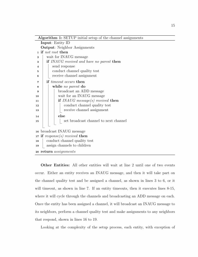
Algorithm 1: SETUP initial setup of the channel assignments
Input: Entity IDOutput: Neighbor Assignments
1 if not root then2 wait for INAUG message3 if INAUG received and have no parent then4 send response5 conduct channel quality test6 receive channel assignment
7 if timeout occurs then8 while no parent do9 broadcast an ADD message
10 wait for an INAUG message11 if INAUG message(s) received then12 conduct channel quality test13 receive channel assignment
14 else15 set broadcast channel to next channel
16 broadcast INAUG message17 if response(s) received then18 conduct channel quality test19 assign channels to children
20 return assignments
Other Entities: All other entities will wait at line 2 until one of two events
occur. Either an entity receives an INAUG message, and then it will take part on
the channel quality test and be assigned a channel, as shown in lines 3 to 6, or it
will timeout, as shown in line 7. If an entity timeouts, then it executes lines 8-15,
where it will cycle through the channels and broadcasting an ADD message on each.
Once the entity has been assigned a channel, it will broadcast an INAUG message to
its neighbors, perform a channel quality test and make assignments to any neighbors
that respond, shown in lines 16 to 19.
Looking at the complexity of the setup process, each entity, with exception of

16
the root, will perform two channel quality tests: one to receive a channel assignment
and one to make assignments. The time for channel quality testing depends on the
number of usable channels in the spectrum, resulting in a complexity of O(2n), where
n is the number of channels. The testing of each individual channel could potentially
increase the complexity, but it is not included here since there exist a number of
methods of measurement, as explained earlier. If an entity times out, it will have to
broadcast ADD messages. Worst case, the entity will have to send an ADD message
on each channel, resulting in a complexity of O(n). Putting these together, the overall
complexity is O(3n), meaning that the setup process depends linearly on the number
of available channels.
3.2.4 Maintaining Link Quality
It is well known that channel quality will vary overtime and is subject to inteference
[21, 22, 27]. In order to keep the communication using only good quality channels,
reassignments can be made as necessary. To avoid the costs of having to redo the
assignments through the entire network, when the quality of a link decreases below
a threshold, the parent entity will send an INAUG message and start the channel
quality test to reassign the link to a better channel.
During reassignment, the entity will try to keep as many of its neighbors in the
same channel as they were previously. However, if an entity gets reassigned to a
channel on which none if its children are assigned, then it will also send an INAUG
message to reassign its children to keep to the design of flow-based assignment.

17
B
C
D
E
A
C2
C2
C1
C3
F
C3
GC2
C1
C2
C1
C1
C2 C3
Primary
Secondary
Figure 3.3: A network with primary (solid line) and secondary (dotted line) channelassignments.
3.3 Reliability Overlap
Alongside low latency and high throughput, a network also needs to be able to reliable
deliver messages. In a dense network, an entity will receive multiple INAUG messages,
meaning it will have several choices from which to select a parent. To achieve increased
reliability in the network, each entity can reply to other INAUG messages even after
being assigned a to channel, and will then have a primary parent and a secondary
parent. The entity will communicate with its primary parent, unless a certain number
of retransmissions is reached or the channel quality on the link drops below a certain
level.
Figure 3.3 shows an example. If entity C experiences multiple failed retransmis-
sions to entity B, then it could transmit to its secondary parent, entity D. For every
entity, there are at least two different paths to the root, and for either path the flow
takes, it tends to stay on the same channel, except where it has to merge with another
flow. In a dense network, reliability could easily be extended to use more than just a
secondary parent.

18
Chapter 4
Simlation Evaluation
To observe the behaviors in larger network scenarios, we created an event-based sim-
ulation for FastLane, as well as the other protocols looked at during evaluation:
RACNet and MMSN. The simulator outputs the packet delivery ratio (PDR) and
the average end-to-end packet latency, and has several parameter settings to observe
the design performance under different network characteristics. Table 4.1 shows the
default parameter values used in the simulations. The limits of channels uses and
number of children per channel only apply to FastLane. The simulation looks at
how network density, number of hops to the root entity, and traffic load and patters
can affect the latency and reliability of the network. Each aspect is simulated inde-
pendently of the other two. Lastly, we also use the simulator to test the reliability
overlap, looking at how the number of parents an entity can have affects the latency
and packet delivery rate.

19
Parameter Description/ValueTopology Layout Grid LayoutTime Per Channel 50 msMaximum Number Of Channels 5Maximum Number Of Children Per Channel 10Number Of Iterations 20/setting
Table 4.1: The default parameters used in the simulation.
4.1 Latency Performance
The latency of the network is measured by recording and averaging the end-to-end
packet delivery latency. A number of simulations are run under varying settings such
as density, number of hops in the network, and traffic load.
4.1.1 Effect of Density
Figures 4.1(a) and 4.1(b) show the effect of network density under two different
traffic patterns. In the case of periodic traffic, every 30 seconds each entity has a
0.5 probability of generating packet. In the random traffic case, entities have a 0.5
probability of generating packet within a 30 second interval. For both traffic patterns,
RACNet and MMSN show a steady increase of latency, approaching 10 seconds when
the density reaches 200 entities. FastLane, however, maintains a much more modest
rate in latency increase as the density increases, with latency staying below 500 ms.
FastLane achieves better latency because multiple entities can transmit at the same
time, and entities have a small number of channels on which to switch between for
listening.

20
1
10
100
1000
10000
100000
0 50 100 150 200 250 300
Av
era
ge
La
ten
cy (
ms)
Avg. Number of Neighbors
FastLane
RACNet
MMSN
(a) periodic traffic
1
10
100
1000
10000
100000
0 50 100 150 200 250 300
Av
era
ge
La
ten
cy (
ms)
Avg. Number of Neighbors
FastLane
RACNet
MMSN
(b) random traffic
Figure 4.1: Latency vs. Density
4.1.2 Effect of Number of Hops
Latency is also observed with regards to the number of hops the farthest entities
are from the root, with two different settings for network density: with 63 neighbors
on average, and with 195 neighbors on average. As can be seen in Figure 4.2(a),
MMSN and RACNet start off at a high latency of around 3 seconds and just over
1 second, respectively. MMSN quickly increases and reaches over 8 seconds with
5 hops. FastLane also shows an increase, but the latency stays significantly less
than MMSN and RACnet, with a latency of 400 ms even at 5 hops. The same
evaluation with a higher density is displayed in Figure 4.2(b), which shows FastLane
again staying less than 1 second while RACNet and MMSN reach a latency of several
seconds. As mentioned with the density results, FastLane allows multiple entities to

21
0
1000
2000
3000
4000
5000
6000
7000
8000
9000
0 1 2 3 4 5 6
Av
era
ge
La
ten
cy (
ms)
Number of Hops
FastLane
RACNet
MMSN
(a) density 63
0
5000
10000
15000
20000
25000
0 1 2 3 4 5 6
Av
era
ge
La
ten
cy (
ms)
Number of Hops
FastLane
RACNet
MMSN
(b) density 195
Figure 4.2: Latency vs. Num. of Hops
be transmitting simultaneously, and entities have only a small number of channel on
which to listen. Also, in FastLane, since a flow is mostly kept on the same channel, an
entity can likely forward a packet right away instead of having to change to another
channel and wait for its neighbor to also switch to that channel.
4.1.3 Effect of Traffic Conditions
The last characteristic observed with respect to latency is traffic load and pattern.
With the density fixed at 63 neighbors on average, the traffic patterns used are:
• Random traffic: Entities have a probability p of generating a packet within
each 10 second interval with p ranging from 0 to 1.

22
0
500
1000
1500
2000
2500
3000
3500
0 0.02 0.04 0.06 0.08 0.1 0.12
Av
era
ge
Le
ten
cy (
ms)
Packets/entity/s
FastLane-R
RACNet-R
MMSN-R
FastLane-P
RACNet-P
MMSN-P
Figure 4.3: Latency vs. Traffic Load
• Periodic traffic: Every 10 seconds, each entity generates a packet with prob-
ability p, with p ranging from 0 to 1.
Figure 4.3 shows how traffic load and pattern affects the performance in terms
of end-to-end latency. Even as the amount of traffic increases, FastLane’s latency
increases slowly and stays under 300 ms even as the amount of traffic increases for
both random and periodic traffic patterns. Meanwhile, the latency in both RACNet
and MMSN increases at a higher rate, especially in the case of periodic traffic, where
they both reach around 3 seconds at higher traffic. FastLane’s performance in higher
traffic is mainly due to the fact that separate flows operate on different channels,
allowing entities to transmit simultaneously. MMSN again suffers because entities
have to operate on too many channels to listen for all of its neighbors.
4.2 PDR Performance
Packet delivery rate at the root entity is used as a metric to measure network re-
liability, and similar to measuring latency performance, the PDR is measured with
respect to three different characteristics: average network density, number of hops in

23
0
20
40
60
80
100
120
0 50 100 150 200 250 300
Pa
cke
t D
eli
ve
ry R
ate
(%
)
Avg. Number of Neighbors
FastLane
RACNet
MMSN
(a) periodic traffic
0
20
40
60
80
100
120
0 50 100 150 200 250 300
Pa
cke
t D
eli
ve
ry R
ate
(%
)
Avg. Number of Neighbors
FastLane
RACNet
MMSN
(b) random traffic
Figure 4.4: Packet Delivery vs. Density
the network, and traffic load and pattern.
4.2.1 Effect of Density
Figures 4.4(a) and 4.4(b) show the effect of network density under two different traf-
fic patterns. While RACNet acheives 100% delivery regardless of density, FastLane
maintains a high delivery rate as the density increases, staying around 97% for ran-
dom traffic and around 90% for periodic traffic as the density reaches 250 neighbors.
FastLane has a decrease in PDR with increasing density due to there being a higher
probability that two neighboring entities cause collisions. MMSN suffers because of
the large number of channels and contention on each channel with which each entity
must deal, and the PDR is below 80% for a high density.
24
4.2.2 Effect of Number of Hops
The reliability is also tested with varying number of hops in the network, with two
setting of a fixed average number of neighbors (63 neighbors and 195 neighbors). As
can be seen in Figures 4.5(a) and 4.5(b), FastLane’s performance drops when the size
of the network becomes more than a few hops, dropping to under 60% as the number
of hops goes beyond 3. This is because as the number of hops increases, entities where
multiple flows converge become more frequent in the network, and entities also must
listen on potentially more channels. An entity to which several flows converge will
need to store more packets and thus, has a higher chance of losing packets due to a
buffer overflow. MMSN suffers from the same reason, and its PDR drops below 60%
when there are more than two hops. RACNet still achieves a high reliability because
of its token passing mechanism. FastLane suffers to a lesser degree than MMSN
because in MMSN entities generally have greater channel diversity, increasing the
complexity of the listening scheme.
4.2.3 Effect of Traffic Conditions
Lastly, the delivery rate is measured with respect to varying traffic rates and traffic
pattern. The same two settings used for simulating latency are used for simulating
PDR. While RACNet is unaffected by traffic load or pattern in regards to delivery rate
and maintains a 100% PDR, Figure 4.6 shows that FastLane exhibits a slight decrease
in performance as the traffic amount increases. However, the PDR of FastLane still is
comparable to that of RACNet, achieving a PDR in the mid 90’s even at the highest
traffic load. Since entities are allowed to transmit simultaneously in FastLane, albeit
spread out amongst different channels, collisions are bound to occur and some packets
will be lost. The PDR of MMSN decreases steadily as the traffic rate increases and

25
0
20
40
60
80
100
120
0 1 2 3 4 5 6
Pa
cke
t D
eli
ve
ry R
ate
(%
)
Number of Hops
FastLane
RACNet
MMSN
(a) density 63
0
20
40
60
80
100
120
0 1 2 3 4 5 6
Pa
cke
t D
eli
ve
ry R
ate
(%
)
Number of Hops
FastLane
RACNet
MMSN
(b) density 195
Figure 4.5: Packet Delivery vs. Numer of Hops
50
60
70
80
90
100
110
0 0.02 0.04 0.06 0.08 0.1 0.12
Pa
cke
t D
eli
ve
ry R
ate
(%
)
Packets/entity/s
FastLane-R
FastLane-P
RACNet-R
RACNet-P
MMSN-R
MMSN-P
Figure 4.6: PDR vs. Traffic Load
drops to mid 80’s, regardless of the traffic pattern.

26
4.3 Reliability Performance
To test the effect that the amount of redundancy in the network has on performance,
we perform simulations where entities have a primary, secondary, or tertiary parent
under varying densities, number of hops, and traffic loads. Our metrics for evaluation
are packet delivery rate and average end-to-end latency.
4.3.1 Effect on Packet Delivery Rate
The delivery rate is observed under varying density, number of hops, and traffic
load of the network. With density testing, each entity periodically generates a packet
every 30 seconds with a probability of 0.5. As expected, with the added redundancy of
multiple parents, the delivery rate increases. Figure 4.7(a) illustrates this. With only
one parent, the PDR drops below 90% when the density approaches 200 neighbors.
At the same density, adding a secondary parent raises the PDR to around 96%, while
adding a tertiary parent shows diminishing returns with a PDR of 97%.
For varying number of hops, the average density is fixed at 63 neighbors, and
entities again generate packets periodically as done with density testing. Figure
4.7(b) displays the results, which reveal that having multiple parents for each entity
significantly increases the delivery rate. At three hops, the PDR goes from around
60% with only a single parent to high 80’s with two or three parents. Similar to
having one parent, the PDR when having multiple parents shows a drop for beyond
three hops, however, there is still a large gain in PDR (>10%) for four and five hops.
Even with multiple parents, FastLane shows a drop in delivery rate for the same
reason explained earlier: as the number of hops increases, multiple flows converging
at an entity occur more frequently meaning that entities must listen on potentially
more and more channels. An entity to which several flows converge may need to wait

27
86
88
90
92
94
96
98
100
102
0 50 100 150 200 250 300
Pa
cke
t D
eli
ve
ry R
ate
(%
)
Avg. Number of Neighbors
FastLane-1
FastLane-2
FastLane-3
(a) PDR vs Density
0
20
40
60
80
100
120
0 1 2 3 4 5 6
Pa
cke
t D
eli
ve
ry R
ate
(%
)
Number of Hops
FastLane-1
FastLane-2
FastLane-3
(b) PDR vs Number of Hops
50
60
70
80
90
100
110
0 0.02 0.04 0.06 0.08 0.1 0.12
Pa
cke
t D
eli
ve
ry R
ate
(%
)
Packets/entity/s
FastLane-1
FastLane-2
FastLane-3
(c) PDR vs Traffic Load
Figure 4.7: PDR performance on the number of parents an entity can have.
longer to cycle to the needed channel and resultantly will need to store more packets
and thus, has a higher chance of losing packets due to a buffer overflow.
Lastly, the delivery rate with multiple parents is measured under different traffic
loads. The network density is fixed at 63 neighbors on average and entities randomly
generate a packet during 10 second intervals with a probability p, where p ranges
from 0 to 1. In Figure 4.7(c), we can observe that having two or three parents as
opposed to only one has minimal effect on the packet delivery rate when it comes to

28
0
50
100
150
200
250
300
350
400
450
500
0 50 100 150 200 250 300
Av
era
ge
La
ten
cy (
ms)
Avg. Number of Neighbors
FastLane-1
FastLane-2
FastLane-3
(a) Latency vs Density
0
50
100
150
200
250
300
350
0 1 2 3 4 5 6
Av
era
ge
La
ten
cy (
ms)
Number of Hops
FastLane-1
FastLane-2
FastLane-3
(b) Latency vs Number of Hops
0
20
40
60
80
100
120
140
160
180
200
0 0.02 0.04 0.06 0.08 0.1 0.12
Av
era
ge
Le
ten
cy (
ms)
Packets/entity/s
FastLane-1
FastLane-2
FastLane-3
FastLane-1
FastLane-2
(c) Latency vs Traffic Load
Figure 4.8: Latency performance on the number of parents an entity can have.
traffic load. For any number of parents, the PDR stays in the mid to high 90’s, with
two and three parents’ delivery rates being 1% or 2% more than single parent when
the traffic load gets high.

29
4.3.2 Effect on Latency
Latency is first looked at under different network densities. With the density varying,
the rest of the network characteristics are the same as for evaluating the packet
delivery rate. At lower densities, the performance is similar for any number of parents.
As Figure 4.8(a) shows though, FastLane with two and three parents per entity starts
to outperform FastLane with one parent when the density reaches 150 and higher.
With only one parent, an entity must wait until it and its parent are on the same
frequency to forward a packet, while with secondary and tertiary parents, entities can
forward packets sooner, as it must only wait until any one of its parents are operating
on the same channel.
Next the latency is looked at with varying number of hops to the root entity.
Again, the density and traffic pattern are the same as when testing the delivery
rate. In general, as the number of hops increases, so does the average end-to-end
latency. This is intuitive, as packets must be transmitted along more links to reach
its destination, regardless of the number of parents to which an entity can transmit.
With more than one parent though, the latency is improved a little bit, especially in
cases of more hops. At 4 hops, the average latency for using a single parent is 290
ms, while for three parents the latency is below 200 ms, shown in Figure 4.8(b). At
one and two hops, the improvement is not as significant since a large number of the
entities can transmit directly to the root.
Under varying traffic loads, the average latency is observed for effects of multiple
parents. With the same settings as measuring packet delivery rate, Figure 4.8(c)
shows the results. Similar to the PDR, the latency does not improve significantly
with increasing number of parent entities. However, as the traffic load increases,
there is a small reduction in the latency, which is due to a similar reason as with

30
density: each entity can transmit when any of its parents are on the same frequency
as it, as opposed to waiting for one specific entity.
4.4 Summary
Through extensive simulation, we have shown the effects that network density, number
of hops, and traffic load have on the performance with respect to end-to-end latency
and packet delivery rate. FastLane makes a slight trade-off between latency and PDR.
While FastLane does not always achieve 100% PDR, it still achieves a PDR of over
90% in most tests, at the same time having significantly better performance in terms
of end-to-end latency.
The delivery rate increases with increasing number of parents because entities can
forward packets to another parent if transmissions to one keep experiencing collisions,
and can forward packets sooner to avoid buffer overflow. Also, by being able to
forward packets sooner, the average end-to-end latency is also reduced when using
multiple parents instead of a single parent.

31
Chapter 5
Discussion
In this section we take a look at points of consideration for use with other netowrk
layers, and potential changes and adaptions to our design to make it more robust and
to fit it to other applications.
5.1 Multi-Channel MAC Compatibility
Since a channel assignment scheme naturally requires a multi-channel MAC protocol,
it needs to be able to work with them and vice versa. When using just a single
parent for each entity, FastLane must wait until the underlying MAC protocol is
operating on the frequency of the parent to transmit packets. When entities have
multiple parents, the implementation can vary. An entity could try transmitting to
each parent in order (primary, secondary, etc.), waiting for the MAC protocol to
switch to the channel of each parent, or it could opportunistically transmit, sending
to the parent whose channel is switched to next.
A MAC protocol could also be designed to be compatible with FastLane. To
perform the channel quality test, FastLane needs to be able to explicitly tell the

32
MAC protocol which channel to use. After setup, the MAC protocol either needs to
routinely cycle through all the channels used by the entity, or to again take commands
to switch to a certain channel. Routinely cycling through the channels would give
fairness to each channel and would require FastLane to wait to transmit until the
MAC protocol switches to the channel of the entities parent. If the MAC protocol
can also take requests to change channel, then FastLane could request the MAC
protocol to change to the parent’s channel when the entity has a packet to send.
5.2 Broadcasting and Flooding
Since there is no common channel amongst all entities and they will be listening
on different channels at a given time, our design brings about a challenges for an
efficient way to broadcast or flood a message. Designating a common channel for
broadcasting and control messages could serve as a simple solution, but a common
channel designated for broadcasting may be a bad channel for some links, meaning
that not all neighbors will receive the message. An alternative to a common channel
is to have the broadcasting entity transmit on each channel that is has assigned to
its neighbors. While it would ensure that all neighbors receive the message, the time
before every neighbor receives the message could be significant.
Flooding has similar challenges as broadcasting, but it brings about more with
the two proposed solutions above. In addition to potential poor quality links, when a
common channel amongst the entities, the delay increases with flooding as the network
grows in hops. This is due to entities constantly switching between channels and when
an entity floods the message on the common channel, not all of its neighbors may
be operating on the common channel at that time. If instead of a common channel,
entities flooded the message on all of its used channels, then packet explosion may

33
occur, which is undesirable.
5.3 Low Duty Cycling
Many applications for wireless devices, such as in wireless sensor networks or even
mobile phones and PDAs, batteries power the devices and thus, they have a limited
power supply. To conserve power and lengthen lifetime, many resource constrained
devices employ low duty cycling with its radio [8, 24]. Low duty cycling introduces
challenges in transmission because not only will each entity be switching between
channels, but its radio will remain off most of the time. This could potentially be
handled with synchronization and the sharing of schedules, as each entity could inform
its neighbors about when in the future it will listen on each channel.
5.4 Limiting Channel Diversity
The number of channels used by each entity to which to assign its neighbors is an
obvious design parameter in FastLane, and other designs as well. As a look to what
effect that can have, we perform a simulation with two different network densities,
where the maximum number of channels an entity is allowed to use in assignments
varies from 1 to 10. Along with FastLane, we simulate the other designs used in the
simulation: RACnet and MMSN. Since each tree in RACnet operates on only one
channel, the results show RACNet’s performance for one channel only.
First we look at the effect it has on the delivery rate (PDR). As Figures 5.1(b)
and 5.1(a) show, at first the PDR quickly increases for both FastLane and MMSN,
because spreading out the communication among a number of channels will obviously
reduce the amount of contention and collisions that occur. At some point though,

34
88
90
92
94
96
98
100
102
0 2 4 6 8 10 12
Pa
cke
t D
eli
ve
ry R
ate
(%
)
Number of Channels
FastLane
RACNet
MMSN
(a) density 63
0
20
40
60
80
100
120
0 2 4 6 8 10 12
Pa
cke
t D
eli
ve
ry R
ate
(%
)
Number of Channels
FastLane
RACNet
MMSN
(b) density 195
Figure 5.1: Packet Delivery vs. Number of Channels
communication can only be spread out so much before the effects are minimal. Figure
5.1(b) shows how going from 1 to 4 channels increases the PDR from low 60’s to mid
90’s. Beyond 4 channels does not result in significant performance increase.
Second, we study the effects that the number of channels has on the end-to-end
packet latency. Figures 5.2(a) and 5.2(a) show similar findings. As the number of
channels used per entity increases, the latency also increases. This is due to the fact
that the more channels that an entity uses, the more time it has to spend listening
on other channels. Obviously, it takes longer for an entity to return to listening to
the same channel.
The effects of the maximum number of channel used per entity are as expected for
a dense network. At first using more channels quickly increases PDR, and then after

35
1
10
100
1000
10000
100000
0 2 4 6 8 10 12
Av
era
ge
La
ten
cy (
ms)
Number of Channels
FastLane
RACNet
MMSN
(a) density 63
1
10
100
1000
10000
100000
0 2 4 6 8 10 12
Av
era
ge
La
ten
cy (
ms)
Number of Channels
FastLane
RACNet
MMSN
(b) density 195
Figure 5.2: Latency vs. Number of Channels
a certain number, the PDR levels off. Using more channels also steadily increases the
latency. This increase though is a trade-off though, because using 3 or 4 channels
in our simulation showed a slight increase in the latency for a large increase in the
delivery rate.

36
Chapter 6
Conclusions
6.1 Summary of Work
Presented in this work was FastLane, the first design of a flow-based channel as-
signment scheme that takes into account channel quality and adapts to variations in
channel quality. Flows in the network are determined and assigned to channels at
network setup. With a flowering process from the root entity, entities perform channel
quality testing with its neighbors, and makes channel assignments, trying to re-use
its assigned channel in order to preserve the per-flow assignment. Through extensive
evaluation with an event-driven simulator, and through implementation in a real test
bed, we show that FastLane achieves significantly better end-to-end latencies while
still maintaining a high packet delivery rate.
6.2 Forward Directions
Although there are many growing applications and ones being developed that must
handle a dense wireless networking environment, the work in this thesis only addresses

37
a specific subset of them. One aspect of research is to achieve high performance
in a dense mesh network and cognitive radio networks. Some challenges presented
are handing more frequencies on which to use, and communication routes traversing
several hops in a network. As seen in the evaluation of FastLane, using multiple
channels causes reliability issues as the number of hops increases.
Another area of future research is using flow-based assignments for networks where
no root entity is present, where flows can start and end arbitrarily. Assigning a flow
to a channel becomes a challenge because the flows are not necessarily known at time
of setup and can be dynamic. Assignment would need to be done on demand as
data needs to be sent. Also, the setup process would need to be simpler for changing
network flows. Addressing this would allow for a more versatile design to handle a
more diverse set of dense networking applications.

38
Bibliography
[1] A. Araujo, J. Garcia-Palacios, J. Blesa, F. Tirado, E. Romero, A. Samartin, and
O. Nieto-Taladriz. Wireless measurement system for structural health monitoring
with high time-synchronization accuracy. Instrumentation and Measurement,
IEEE Transactions on, 61(3):801 –810, march 2012.
[2] M. Audeh. Metropolitan-scale wi-fi mesh networks. Computer, 37(12):119 – 121,
dec. 2004.
[3] Paramvir Bahl, Ranveer Chandra, and John Dunagan. Ssch: slotted seeded chan-
nel hopping for capacity improvement in ieee 802.11 ad-hoc wireless networks.
In Proceedings of the 10th annual international conference on Mobile computing
and networking, MobiCom ’04, pages 216–230, New York, NY, USA, 2004. ACM.
[4] Sanjit Biswas and Robert Morris. Exor: opportunistic multi-hop routing for
wireless networks. In Proceedings of the 2005 conference on Applications, tech-
nologies, architectures, and protocols for computer communications, SIGCOMM
’05, pages 133–144, New York, NY, USA, 2005. ACM.
[5] Marianna Carrera, Henrik Lundgren, Theodoros Salonidis, and Christophe Diot.
A cross-layer load-independent link cost metric for wireless mesh networks. In
Proceedings of the 2007 ACM CoNEXT conference, CoNEXT ’07, pages 72:1–
72:2, New York, NY, USA, 2007. ACM.

39
[6] Ding Chen-li, Zhang Guo-an, Gu Jin-yuan, and Bao Zhi-hua. A route tree-based
channel assignment algorithm in cognitive wireless mesh networks. In Wireless
Communications Signal Processing, 2009. WCSP 2009. International Conference
on, pages 1–5, 2009.
[7] Kwan-Wu Chin, John Judge, Aidan Williams, and Roger Kermode. Implemen-
tation experience with manet routing protocols. SIGCOMM Comput. Commun.
Rev., 32(5):49–59, November 2002.
[8] D. Culler, D. Estrin, and M. Srivastava. Guest editors’ introduction: Overview
of sensor networks. Computer, 37(8):41–49, 2004.
[9] Douglas S. J. De Couto, Daniel Aguayo, John Bicket, and Robert Morris. A high-
throughput path metric for multi-hop wireless routing. Wirel. Netw., 11(4):419–
434, July 2005.
[10] Mohamed Ali Feki, Fahim Kawsar, Mathieu Boussard, and Lieven Trappeniers.
The internet of things: The next technological revolution. Computer, 46(2):24–
25, 2013.
[11] Weihuang Fu, Bin Xie, D.P. Agrawal, and A. Kumar. A tree-based channel
assignment scheme for wireless mesh networks. In Mobile Adhoc and Sensor
Systems, 2007. MASS 2007. IEEE Internatonal Conference on, pages 1–6, 2007.
[12] Weihuang Fu, Bin Xie, Xiaoyuan Wang, and D.P. Agrawal. Flow-based channel
assignment in channel constrained wireless mesh networks. In Computer Com-
munications and Networks, 2008. ICCCN ’08. Proceedings of 17th International
Conference on, pages 1–6, 2008.

40
[13] Omprakash Gnawali, Rodrigo Fonseca, Kyle Jamieson, David Moss, and Philip
Levis. Collection tree protocol. In Proceedings of the 7th ACM Conference on
Embedded Networked Sensor Systems, SenSys ’09, pages 1–14, New York, NY,
USA, 2009. ACM.
[14] Carl Hartung, Richard Han, Carl Seielstad, and Saxon Holbrook. Firewxnet: a
multi-tiered portable wireless system for monitoring weather conditions in wild-
land fire environments. In Proceedings of the 4th international conference on
Mobile systems, applications and services, MobiSys ’06, pages 28–41, New York,
NY, USA, 2006. ACM.
[15] Felix Juraschek, Mesut Gunes, Matthias Philipp, and Bastian Blywis. On the fea-
sibility of distributed link-based channel assignment in wireless mesh networks.
In Proceedings of the 9th ACM international symposium on Mobility manage-
ment and wireless access, MobiWac ’11, pages 9–18, New York, NY, USA, 2011.
ACM.
[16] Srinivasan Keshav. A control-theoretic approach to flow control. In Proceedings
of the conference on Communications architecture & protocols, SIGCOMM ’91,
pages 3–15, New York, NY, USA, 1991. ACM.
[17] Youngmin Kim, Hyojeong Shin, and Hojung Cha. Y-mac: An energy-efficient
multi-channel mac protocol for dense wireless sensor networks. In Proceedings of
the 7th international conference on Information processing in sensor networks,
IPSN ’08, pages 53–63, Washington, DC, USA, 2008. IEEE Computer Society.
[18] Murali Kodialam and Thyaga Nandagopal. Characterizing the capacity region
in multi-radio multi-channel wireless mesh networks. In Proceedings of the 11th

41
annual international conference on Mobile computing and networking, MobiCom
’05, pages 73–87, New York, NY, USA, 2005. ACM.
[19] Hieu Khac Le, Dan Henriksson, and Tarek Abdelzaher. A control theory ap-
proach to throughput optimization in multi-channel collection sensor networks.
In Proceedings of the 6th international conference on Information processing in
sensor networks, IPSN ’07, pages 31–40, New York, NY, USA, 2007. ACM.
[20] Chieh-Jan Mike Liang, Jie Liu, Liqian Luo, Andreas Terzis, and Feng Zhao.
Racnet: a high-fidelity data center sensing network. In Proceedings of the 7th
ACM Conference on Embedded Networked Sensor Systems, SenSys ’09, pages
15–28, New York, NY, USA, 2009. ACM.
[21] Chieh-Jan Mike Liang, Nissanka Bodhi Priyantha, Jie Liu, and Andreas Terzis.
Surviving wi-fi interference in low power zigbee networks. In Proceedings of the
8th ACM Conference on Embedded Networked Sensor Systems, SenSys ’10, pages
309–322, New York, NY, USA, 2010. ACM.
[22] R. Maheshwari, Jing Cao, and S.R. Das. Physical interference modeling for
transmission scheduling on commodity wifi hardware. In INFOCOM 2009, IEEE,
pages 2661–2665, 2009.
[23] Chandrakant D. Patel, Cullen E. Bash, Ratnesh Sharma, Monem Beitelmal, and
Rich Friedrich. Smart cooling of data centers. ASME Conference Proceedings,
2003(36908b):129–137, 2003.
[24] Joseph Polastre, Jason Hill, and David Culler. Versatile low power media access
for wireless sensor networks. In Proceedings of the 2nd international conference
on Embedded networked sensor systems, SenSys ’04, pages 95–107, New York,
NY, USA, 2004. ACM.

42
[25] Jatinder Pal Singh, Tansu Alpcan, Piyush Agrawal, and Varun Sharma. A
markov decision process based flow assignment framework for heterogeneous net-
work access. Wirel. Netw., 16(2):481–495, February 2010.
[26] Jungmin So and Nitin H. Vaidya. Multi-channel mac for ad hoc networks: han-
dling multi-channel hidden terminals using a single transceiver. In Proceedings
of the 5th ACM international symposium on Mobile ad hoc networking and com-
puting, MobiHoc ’04, pages 222–233, New York, NY, USA, 2004. ACM.
[27] Kannan Srinivasan, Maria A. Kazandjieva, Saatvik Agarwal, and Philip Levis.
The β-factor: measuring wireless link burstiness. In Proceedings of the 6th
ACM conference on Embedded network sensor systems, SenSys ’08, pages 29–42,
New York, NY, USA, 2008. ACM.
[28] Jun Sun and Marshall Scott Poole. Beyond connection: situated wireless com-
munities. Commun. ACM, 53(6):121–125, June 2010.
[29] Robert Szewczyk, Alan Mainwaring, Joseph Polastre, John Anderson, and David
Culler. An analysis of a large scale habitat monitoring application. In Proceed-
ings of the 2nd international conference on Embedded networked sensor systems,
SenSys ’04, pages 214–226, New York, NY, USA, 2004. ACM.
[30] Lei Tang, Yanjun Sun, Omer Gurewitz, and David B. Johnson. Em-mac: a
dynamic multichannel energy-efficient mac protocol for wireless sensor networks.
In Proceedings of the Twelfth ACM International Symposium on Mobile Ad Hoc
Networking and Computing, MobiHoc ’11, pages 23:1–23:11, New York, NY,
USA, 2011. ACM.
[31] Ramanuja Vedantham, Sandeep Kakumanu, Sriram Lakshmanan, and Raghu-
pathy Sivakumar. Component based channel assignment in single radio, multi-

43
channel ad hoc networks. In Proceedings of the 12th annual international confer-
ence on Mobile computing and networking, MobiCom ’06, pages 378–389, New
York, NY, USA, 2006. ACM.
[32] Yafeng Wu, J.A. Stankovic, Tian He, and Shan Lin. Realistic and efficient multi-
channel communications in wireless sensor networks. In INFOCOM 2008. The
27th Conference on Computer Communications. IEEE, pages 1193 –1201, april
2008.
[33] Kai Xing, Xiuzhen Cheng, Liran Ma, and Qilian Liang. Superimposed code
based channel assignment in multi-radio multi-channel wireless mesh networks.
In Proceedings of the 13th annual ACM international conference on Mobile com-
puting and networking, MobiCom ’07, pages 15–26, New York, NY, USA, 2007.
ACM.
[34] Jingbin Zhang, Gang Zhou, Chengdu Huang, Sang H. Son, and John A.
Stankovic. Tmmac: An energy efficient multi-channel mac protocol for ad hoc
networks. In in IEEE ICC, 2007.
[35] Changliang Zheng, Ren Ping Liu, Xun Yang, I.B. Collings, Zheng Zhou, and
E. Dutkiewicz. Maximum flow-segment based channel assignment and routing
in cognitive radio networks. In Vehicular Technology Conference (VTC Spring),
2011 IEEE 73rd, pages 1–6, 2011.
[36] G. Zhou, C. Huang, T. Yan, T. He, J. A. Stankovic, and T. F. Abdelzaher.
Mmsn: Multi-frequency media access control for wireless sensor networks. In
INFOCOM 2006. 25th IEEE International Conference on Computer Communi-
cations. Proceedings, pages 1 –13, april 2006.