fastmig - kemppi · wire spool. wire feeders can be used with fastmig pulse, fastmig kms and...
TRANSCRIPT

FastMigMXF 63, 65, 67
Operating manual
Brugsanvisning
Gebrauchsanweisung
Manual de instrucciones
Käyttöohje
Manuel d’utilisation
Manuale d’uso
Gebruiksaanwijzing
Bruksanvisning
Instrukcja obsługi
Manual de utilização
Инструкции по эксплуатации
Bruksanvisning
操作手册
EN
DA
DE
ES
FI
FR
IT
NL
NO
PL
PT
RU
SV
ZH


OPERATING MANUALEnglish

EN
CONTENTS
1. Preface . . . . . . . . . . . . . . . . . . . . . . . . . . . . . . . . . . . . . . . . . . . . . . . . . . . . . . . . . . . . . . . . . . . . . . . . . . . . . . . . . . . . . . . . . . . . . . . . . . . . . . . . . . . 31.1 General . . . . . . . . . . . . . . . . . . . . . . . . . . . . . . . . . . . . . . . . . . . . . . . . . . . . . . . . . . . . . . . . . . . . . . . . . . . . . . . . . . . . . . . . . . . . . . . . . . . . . . . . . . . . . . . . . . . . . . . . . . . . . . . . . . . . . . . 31.2 About FastMig products . . . . . . . . . . . . . . . . . . . . . . . . . . . . . . . . . . . . . . . . . . . . . . . . . . . . . . . . . . . . . . . . . . . . . . . . . . . . . . . . . . . . . . . . . . . . . . . . . . . . . . 3
2. Installation . . . . . . . . . . . . . . . . . . . . . . . . . . . . . . . . . . . . . . . . . . . . . . . . . . . . . . . . . . . . . . . . . . . . . . . . . . . . . . . . . . . . . . . . . . . . . . . . . . . . 42.1 Machine introduction, MXF 65, MXF 67 and MXF 63 . . . . . . . . . . . . . . . . . . . . . . . . . . . . . . . . . . . . . . . . . . . . . . . . 42.2 Connection of system . . . . . . . . . . . . . . . . . . . . . . . . . . . . . . . . . . . . . . . . . . . . . . . . . . . . . . . . . . . . . . . . . . . . . . . . . . . . . . . . . . . . . . . . . . . . . . . . . . . . . . . . . . . 52.3 Assembly of MIG/MAG system . . . . . . . . . . . . . . . . . . . . . . . . . . . . . . . . . . . . . . . . . . . . . . . . . . . . . . . . . . . . . . . . . . . . . . . . . . . . . . . . . . . . . . . . . . 62.4 Accessories corresponding to wire diameter . . . . . . . . . . . . . . . . . . . . . . . . . . . . . . . . . . . . . . . . . . . . . . . . . . . . . . . . . . . . . . 72.5 Welding gun selection . . . . . . . . . . . . . . . . . . . . . . . . . . . . . . . . . . . . . . . . . . . . . . . . . . . . . . . . . . . . . . . . . . . . . . . . . . . . . . . . . . . . . . . . . . . . . . . . . . . . . . . . . . 72.6 Mounting and locking of wire spool . . . . . . . . . . . . . . . . . . . . . . . . . . . . . . . . . . . . . . . . . . . . . . . . . . . . . . . . . . . . . . . . . . . . . . . . . . . . . . . 72.7 Loading the filler wire and automatic feed . . . . . . . . . . . . . . . . . . . . . . . . . . . . . . . . . . . . . . . . . . . . . . . . . . . . . . . . . . . . . . . . . . 82.8 DuraTorque™ 400, 4-wheel wire feed mechanism . . . . . . . . . . . . . . . . . . . . . . . . . . . . . . . . . . . . . . . . . . . . . . . . . . . . . 82.9 Wire liners . . . . . . . . . . . . . . . . . . . . . . . . . . . . . . . . . . . . . . . . . . . . . . . . . . . . . . . . . . . . . . . . . . . . . . . . . . . . . . . . . . . . . . . . . . . . . . . . . . . . . . . . . . . . . . . . . . . . . . . . . . . . . . . . 102.10 Adjustment of pressure arms . . . . . . . . . . . . . . . . . . . . . . . . . . . . . . . . . . . . . . . . . . . . . . . . . . . . . . . . . . . . . . . . . . . . . . . . . . . . . . . . . . . . . . . . . . . 112.11 Adjustment of spool brake . . . . . . . . . . . . . . . . . . . . . . . . . . . . . . . . . . . . . . . . . . . . . . . . . . . . . . . . . . . . . . . . . . . . . . . . . . . . . . . . . . . . . . . . . . . . . . . 112.12 Burn back time . . . . . . . . . . . . . . . . . . . . . . . . . . . . . . . . . . . . . . . . . . . . . . . . . . . . . . . . . . . . . . . . . . . . . . . . . . . . . . . . . . . . . . . . . . . . . . . . . . . . . . . . . . . . . . . . . . . . . . 112.13 Earth return cable . . . . . . . . . . . . . . . . . . . . . . . . . . . . . . . . . . . . . . . . . . . . . . . . . . . . . . . . . . . . . . . . . . . . . . . . . . . . . . . . . . . . . . . . . . . . . . . . . . . . . . . . . . . . . . . . . 112.14 Shielding gas . . . . . . . . . . . . . . . . . . . . . . . . . . . . . . . . . . . . . . . . . . . . . . . . . . . . . . . . . . . . . . . . . . . . . . . . . . . . . . . . . . . . . . . . . . . . . . . . . . . . . . . . . . . . . . . . . . . . . . . . . . 122.15 Main switch I/O . . . . . . . . . . . . . . . . . . . . . . . . . . . . . . . . . . . . . . . . . . . . . . . . . . . . . . . . . . . . . . . . . . . . . . . . . . . . . . . . . . . . . . . . . . . . . . . . . . . . . . . . . . . . . . . . . . . . . 132.16 Operation of cooling unit, FastCool 10 . . . . . . . . . . . . . . . . . . . . . . . . . . . . . . . . . . . . . . . . . . . . . . . . . . . . . . . . . . . . . . . . . . . . . . . . 132.17 MXF hanging kit . . . . . . . . . . . . . . . . . . . . . . . . . . . . . . . . . . . . . . . . . . . . . . . . . . . . . . . . . . . . . . . . . . . . . . . . . . . . . . . . . . . . . . . . . . . . . . . . . . . . . . . . . . . . . . . . . . . . 14
3. Control panel operations . . . . . . . . . . . . . . . . . . . . . . . . . . . . . . . . . . . . . . . . . . . . . . . . . . . . . . . . . . . . . . . . . . . . . . . . 153.1 Connecting and mounting . . . . . . . . . . . . . . . . . . . . . . . . . . . . . . . . . . . . . . . . . . . . . . . . . . . . . . . . . . . . . . . . . . . . . . . . . . . . . . . . . . . . . . . . . . . . . . . 15
4. Welding software delivery profile . . . . . . . . . . . . . . . . . . . . . . . . . . . . . . . . . . . . . . . . . . . . . . . . . . . . . . . . 16
5. Panel button functions . . . . . . . . . . . . . . . . . . . . . . . . . . . . . . . . . . . . . . . . . . . . . . . . . . . . . . . . . . . . . . . . . . . . . . . . . . . 195.1 PF 63 and PF 65 control panel for FastMig Pulse . . . . . . . . . . . . . . . . . . . . . . . . . . . . . . . . . . . . . . . . . . . . . . . . . . . . . . 195.2 PF 63 and PF 65 control panel button functions . . . . . . . . . . . . . . . . . . . . . . . . . . . . . . . . . . . . . . . . . . . . . . . . . . . . . . 205.3 SF 51 and 54 control panel for FastMig KMS . . . . . . . . . . . . . . . . . . . . . . . . . . . . . . . . . . . . . . . . . . . . . . . . . . . . . . . . . . . . . . 235.4 SF 52W and 53W control panel for FastMig KMS . . . . . . . . . . . . . . . . . . . . . . . . . . . . . . . . . . . . . . . . . . . . . . . . . . . . . 245.5 MS 200 and MS 300 control panel for FastMig M . . . . . . . . . . . . . . . . . . . . . . . . . . . . . . . . . . . . . . . . . . . . . . . . . . . . . 255.6 MR 200 and MR 300 control panel for FastMig M . . . . . . . . . . . . . . . . . . . . . . . . . . . . . . . . . . . . . . . . . . . . . . . . . . . . 26
6. Basic troubleshooting . . . . . . . . . . . . . . . . . . . . . . . . . . . . . . . . . . . . . . . . . . . . . . . . . . . . . . . . . . . . . . . . . . . . . . . . . . . . . 27
7. Maintenance . . . . . . . . . . . . . . . . . . . . . . . . . . . . . . . . . . . . . . . . . . . . . . . . . . . . . . . . . . . . . . . . . . . . . . . . . . . . . . . . . . . . . . . . . . . . . . 287.1 Daily maintenance . . . . . . . . . . . . . . . . . . . . . . . . . . . . . . . . . . . . . . . . . . . . . . . . . . . . . . . . . . . . . . . . . . . . . . . . . . . . . . . . . . . . . . . . . . . . . . . . . . . . . . . . . . . . . . . 287.2 Service shop maintenance . . . . . . . . . . . . . . . . . . . . . . . . . . . . . . . . . . . . . . . . . . . . . . . . . . . . . . . . . . . . . . . . . . . . . . . . . . . . . . . . . . . . . . . . . . . . . . . 28
8. Disposal of the machine . . . . . . . . . . . . . . . . . . . . . . . . . . . . . . . . . . . . . . . . . . . . . . . . . . . . . . . . . . . . . . . . . . . . . . . . . 28
9. Ordering numbers . . . . . . . . . . . . . . . . . . . . . . . . . . . . . . . . . . . . . . . . . . . . . . . . . . . . . . . . . . . . . . . . . . . . . . . . . . . . . . . . . . . . 29
10. Technical data . . . . . . . . . . . . . . . . . . . . . . . . . . . . . . . . . . . . . . . . . . . . . . . . . . . . . . . . . . . . . . . . . . . . . . . . . . . . . . . . . . . . . . . . . . . . 33
FastMig MXF 63, 65, 672

EN
1. PREFACE
1.1 GeneralCongratulations on choosing the FastMig MXF equipment. Used correctly, Kemppi products can significantly increase the productivity of your welding, and provide years of economical service. This operating manual contains important information on the use, maintenance and safety of your Kemppi product. The technical specifications of the equipment can be found at the end of the manual. Please read the operating manual and the safety instructions booklet carefully before using the equipment for the first time. For your own safety and that of your working environment, pay particular attention to the safety instructions in the manual.For more information on Kemppi products, contact Kemppi Oy, consult an authorised Kemppi dealer, or visit the Kemppi web site at www.kemppi.com.The specifications presented in this manual are subject to change without prior notice.
Important notesItems in the manual that require particular attention in order to minimise damage and personal harm are indicated with the ’NOTE!’ notation. Read these sections carefully and follow their instructions.
DisclaimerWhile every effort has been made to ensure that the information contained in this guide is accurate and complete, no liability can be accepted for any errors or omissions. Kemppi reserves the right to change the specification of the product described at any time without prior notice. Do not copy, record, reproduce or transmit the contents of this guide without prior permission from Kemppi.
1.2 About FastMig productsKemppi FastMig™ MXF 63, MXF 65 and MXF 67 are wire feeders designed for demanding professional use. MXF 63 is intended for 200 mm wire spool, MXF 65 and MXF 67 for 300 mm wire spool. Wire feeders can be used with FastMig Pulse, FastMig KMS and FastMig M power sources. Which alternative panel to choose for MXF 63, 65 and 67 depends on the used power source i.e. FastMig KMS becomes compatible by connecting SF 51, SF 52W, SF 53W or SF 54 control panels with MXF wire feed unit, and in the case of PF 63 and PF 65 control panels FastMig Pulse power source can be connected. With FastMig M the MR 200, MR 300, MS 200 or MS 300 panels are used. Operation of wire feed units is controlled and adjusted by microprocessor. By adding an optional synchronization unit (MXF Sync 65), SuperSnake sub-feeder device may be connected to MXF 63, 65 and 67.This manual provides instructions on the start-up and use of the MXF 63, 65 and 67 MIG/MAG wire feeding units.
3© Kemppi Oy / 1736

EN
2. INSTALLATION
2.1 Machine introduction, MXF 63, MXF 65 and MXF 67
WF #
5.
5.
1.
1.
3.
2.
2.3.
4.
1. Control panel2. Remote control connector3. Sub-feeder sync connector (kit optional)4. Gun water connections (cooling optional) 5. Euro gun connector
6.
7.
8.
9.
8.
7.
6.
9.
6. Shielding gas connection7. Connection for control cable8. Welding current cable connector9. Lead-in and clamping of cooling liquid hoses
FastMig MXF 63, 65, 674
EN
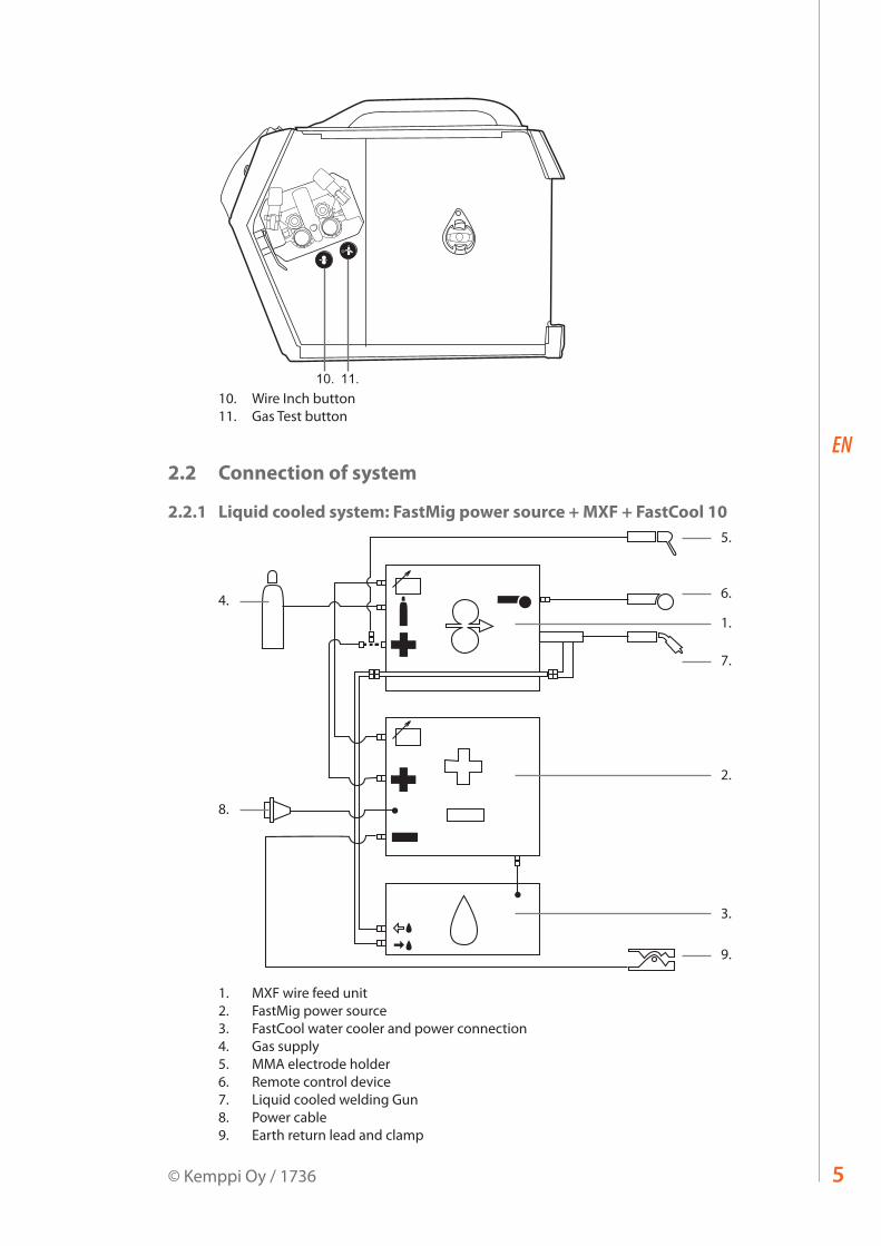
10. 11.10. Wire Inch button11. Gas Test button
2.2 Connection of system
2.2.1 Liquid cooled system: FastMig power source + MXF + FastCool 10
1.
4.
8.
2.
3.
9.
5.
6.
7.
1. MXF wire feed unit2. FastMig power source3. FastCool water cooler and power connection4. Gas supply5. MMA electrode holder6. Remote control device7. Liquid cooled welding Gun8. Power cable9. Earth return lead and clamp
5© Kemppi Oy / 1736

EN
2.2.2 Air cooled system: FastMig power source + MXF
1.
4.
5.
6.
8.
2.
3.
7.
1. MXF wire feed unit2. FastMig power source3. Gas supply4. MMA electrode holder5. Remote control device6. Air cooled welding gun7. Power cable8. Earth return lead and clamp
2.3 Assembly of MIG/MAG systemAssemble the units in the order mentioned below. Follow the additional mounting and operating instructions delivered with each package.
1. Installation of power sourceRead paragraph: ”Installation” in the operation instructions for FastMig power sources, and complete the installation according to that advice.
2. Mounting of power sources to transport wagonRead and follow the instructions given in the transport cart installation/assembly manual.
3. Mounting the FastMig MXF wire feed unit to the power sourceRemove the cover sticker on top of the power source. Screw the fastening pivot into the power source – hand tighten only. Place the supplied plastic spacers over the pivot. Lift the MXF wire feeder into place, locating over the pivot.
4. Connecting cablesConnect the cables in accordance with the equipment notes provided in this manual.The polarity of the welding wire (+ or –) can be selected by connecting the wire feed unit to either the positive or the negative power source terminals.Most MIG/MAG applications run the wire feed unit connected to the positive terminal of the power source.
5. Mounting FastMig wire feed units to boom and swing armsWhen mounting wire feed units to boom and swing arms, the unit must be electrically isolated from both.Suspension angle of wire feed unit can be changed by moving the fixing point in handle.
FastMig MXF 63, 65, 676

EN
2.4 Accessories corresponding to wire diameterColour coded wire feed rolls and guide tubes are available to suit a variety of filler wire types and sizes. Drive roll groove geometry and design vary depending on the application. Further details are available in the spare part tables.Please ensure you select the correct drive rolls and guide tubes from the table to suit your particular welding application.
2.5 Welding gun selectionPlease ensure that the welding gun selected is suitable for the target application. Check the gun manufacturer's specification and ensure the gun meets the welding duty requirements. Also consider the extra heating effects of Pulse MIG/MAG welding on the gun selected.Kemppi gun products are designed to meet many different applications. Special wire liners and contact tips are available for different wire types and sizes.Distance wire feeding is accommodated with WeldSnake and SuperSnake products in either air or liquid cooled models.Thermal and load protection is also designed to some Kemppi Gun models and feed units, so carefully consider your requirements and consult your local Kemppi sales team to ensure you choose the correct alternative for your needs.
2.6 Mounting and locking of wire spool
NOTE! Check that the filler wire spool is correctly mounted and locked into position. Ensure the spool is not damaged or deformed in such a way that it can rub or chaff against the internal surface of the wire feed unit chassis or door. This may result in increased drag, impacting on weld quality. This may also result in long term wire feed unit damage, rendering the unit unserviceable or unsafe to use.
7© Kemppi Oy / 1736

EN
2.7 Loading the filler wire and automatic feedAutomatic wire feed makes wire spool changes faster. When changing the wire spool, the pressure of feed rolls need to be released.Simply ensure that the groove of the feed roll matches the diameter of filler wire used. Release the wire end from the spool and cut off any deformed section. Be careful the wire does not spill from the spool sides.Straighten about 20 cm of filler wire and ensure the tip has no sharp edges. File if necessary, as a sharp wire edge may damage the wire gun liner - particularly softer plastic liners.Present the filler wire tip to the back of the wire feed rolls and press the Wire Inch button on the wire feed panel or use the switch inside the wire spool cabinet. Feed the wire to the gun contact tip and prepare to weld.
NOTE! Smaller diameter filler wires may need to be loaded manually – with the feed roll pressure arms released. This is because it is easy to overestimate the pressure required to feed these smaller filler wires. Too high feed roll pressures can easily deform filler wires and contribute to later feeding problems.
2.8 DuraTorque™ 400, 4-wheel wire feed mechanismWire guide tubes
ø mm outlet tube middle tube inlet tubeSs, Al, (Fe, Mc, Fc)plastic
0.6 SP007437 SP007429 SP007293
0.8 – 0.9 SP007438 SP007430 SP007294
1.0 SP007439 SP007431 SP007295
1.2 SP007440 SP007432 SP007296
1.4 SP007441 SP007433 SP007297
1.6 SP007442 SP007434 SP007298
2.0 SP007443 SP007435 SP007299
2.4 SP007444 SP007436 SP007300
Fe, Mc, Fcmetal
0.8 – 0.9 SP007454 SP007465 SP007536
1.0 SP007455 SP007466 SP007537
1.2 SP007456 SP007467 SP007538
1.4 – 1.6 SP007458 SP007469 SP007539
2.0 SP007459 SP007470 SP007540
2.4 SP007460 SP007471 SP007541
24.8.2005 12:55
FastMig MXF 63, 65, 678
EN
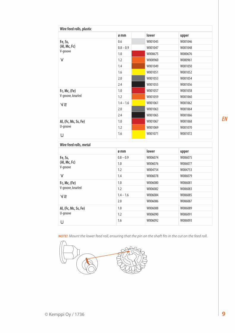
Wire feed rolls, plasticø mm lower upper
Fe, Ss, (Al, Mc, Fc)V-groove
0.6 W001045 W001046
0.8 – 0.9 W001047 W001048
1.0 W000675 W000676
1.2 W000960 W000961
1.4 W001049 W001050
1.6 W001051 W001052
2.0 W001053 W001054
2.4 W001055 W001056
Fc, Mc, (Fe)V-groove, knurled
1.0 W001057 W001058
1.2 W001059 W001060
1.4 – 1.6 W001061 W001062
2.0 W001063 W001064
2.4 W001065 W001066
Al, (Fc, Mc, Ss, Fe)U-groove
1.0 W001067 W001068
1.2 W001069 W001070
1.6 W001071 W001072
Wire feed rolls, metalø mm lower upper
Fe, Ss, (Al, Mc, Fc)V-groove
0.8 – 0.9 W006074 W006075
1.0 W006076 W006077
1.2 W004754 W004753
1.4 W006078 W006079
Fc, Mc, (Fe)V-groove, knurled
1.0 W006080 W006081
1.2 W006082 W006083
1.4 – 1.6 W006084 W006085
2.0 W006086 W006087
Al, (Fc, Mc, Ss, Fe)U-groove
1.0 W006088 W006089
1.2 W006090 W006091
1.6 W006092 W006093
NOTE! Mount the lower feed roll, ensuring that the pin on the shaft fits in the cut on the feed roll.
9© Kemppi Oy / 1736
EN
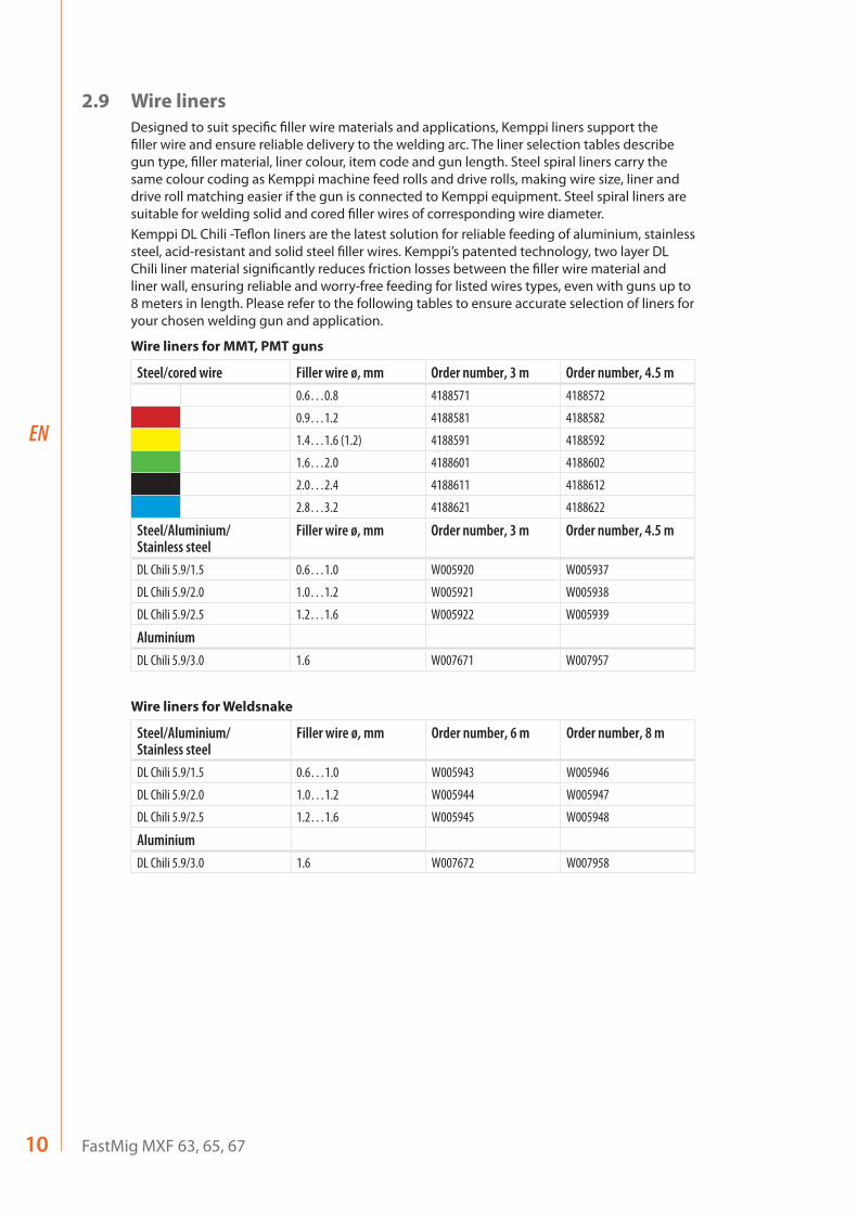
2.9 Wire linersDesigned to suit specific filler wire materials and applications, Kemppi liners support the filler wire and ensure reliable delivery to the welding arc. The liner selection tables describe gun type, filler material, liner colour, item code and gun length. Steel spiral liners carry the same colour coding as Kemppi machine feed rolls and drive rolls, making wire size, liner and drive roll matching easier if the gun is connected to Kemppi equipment. Steel spiral liners are suitable for welding solid and cored filler wires of corresponding wire diameter.Kemppi DL Chili -Teflon liners are the latest solution for reliable feeding of aluminium, stainless steel, acid-resistant and solid steel filler wires. Kemppi’s patented technology, two layer DL Chili liner material significantly reduces friction losses between the filler wire material and liner wall, ensuring reliable and worry-free feeding for listed wires types, even with guns up to 8 meters in length. Please refer to the following tables to ensure accurate selection of liners for your chosen welding gun and application.
Wire liners for MMT, PMT guns
Steel/cored wire Filler wire ø, mm Order number, 3 m Order number, 4.5 m0.6…0.8 4188571 4188572
0.9…1.2 4188581 4188582
1.4…1.6 (1.2) 4188591 4188592
1.6…2.0 4188601 4188602
2.0…2.4 4188611 4188612
2.8…3.2 4188621 4188622
Steel/Aluminium/ Stainless steel
Filler wire ø, mm Order number, 3 m Order number, 4.5 m
DL Chili 5.9/1.5 0.6…1.0 W005920 W005937
DL Chili 5.9/2.0 1.0…1.2 W005921 W005938
DL Chili 5.9/2.5 1.2…1.6 W005922 W005939
AluminiumDL Chili 5.9/3.0 1.6 W007671 W007957
Wire liners for Weldsnake
Steel/Aluminium/ Stainless steel
Filler wire ø, mm Order number, 6 m Order number, 8 m
DL Chili 5.9/1.5 0.6…1.0 W005943 W005946
DL Chili 5.9/2.0 1.0…1.2 W005944 W005947
DL Chili 5.9/2.5 1.2…1.6 W005945 W005948
AluminiumDL Chili 5.9/3.0 1.6 W007672 W007958
FastMig MXF 63, 65, 6710

EN
2.10 Adjustment of pressure armsAdjust the drive pressure to the filler wire with the thumb screws mounted over the pressure arms. Notice the graduated scales indicating load. The load applied should be sufficient to overcome a light braking force applied by hand to the filler wire, as it exits the welding gun contact tip.For smaller diameter and soft filler wires, less feed pressure is required. It should be possible to apply a light breaking force to the filler wire by hand, as it exits the gun contact tip. But slightly more wire flow restriction should render the drives rolls to slip slightly over the filler wire without deforming the wire.
NOTE! Excessive pressure causes flattening of the filler wire and damage to coated or cored filler wires. It also causes undue wear of the feed rolls and increases gearbox load, so reducing service life.
2.11 Adjustment of spool brakeBrake force is adjusted through the hole behind the locking clip. Remove the locking clip by hand, and adjust the tension and pressure to the friction pads mounted inside with a screw driver. See diagram and location A.
A
The load applied varies depending on the size and weight of the filler wire and spool, but also the filler wire feed speed set. The heavier the wire spool and the faster the feed speed, the greater the need to increase the braking load. Adjust the pressure, secure the locking clip, set the wire feed speed and check that the braking force is enough to ensure the filler wire does not spill from the spool on overrun.
NOTE! Too much or unnecessary loads can impact welding quality, load and wear to the wire feed system.
2.12 Burn back timeFastMig electronics controls the burn back time. When welding stops, an automatic sequence ensures that the filler wire does not stick to the work piece and that no ball is formed at the wire tip, ensuring reliable re-ignition. This system works regardless of the wire feed speed set.
2.13 Earth return cablePreferably the earth return cable and clamp should be connected directly to the welding material.Always use a good quality, 70 mm2 heavy copper cable, and if possible a screw type 600 A clamp. Ensure that the surface contact to the work piece is clean of metal oxide and or paint. Make sure the clamp is firmly secured.
11© Kemppi Oy / 1736

EN
2.14 Shielding gasNOTE! Handle shielding gas bottle with care. Assess the risks associated with handling and using compressed gas. Always use a cylinder transport carriage and secure the cylinder safely.
There are many different suppliers of quality shielding gases for welding. Please ensure that you are selecting the correct gas for your application. FastMig products uses welding programs for Synergic and Pulsed welding. These curves are created and recommend against a particular shielding gas.Shielding gas effects welding performance and is a fundamental component to overall weld quality.
MMT 32
l/min
5
10
15
20
NOTE! Shielding gas flow rate from the welding gun is set according to the application, weld joint, gas type and gas nozzle shape and size. The flow rate should be measured at the welding gun nozzle before welding via a rotameter, and normally measure's between 10 – 20 litres per minute for many welding applications.
2.14.1 Installing gas bottleAlways fasten the gas bottle properly in the vertical position, in a special holder against the wall or on a cylinder carriage. Remember to close gas bottle valve after welding.
Parts of gas flow regulator
5
2
4
7
1 63
1. Gas bottle valve2. Flow regulation screw3. Connecting nut4. Hose tail5. Hose tail nut6. Gas bottle pressure gauge7. Shielding gas flow meter
FastMig MXF 63, 65, 6712
EN
2.15 Main switch I/OWhen you turn the main switch of the FastMig power source into I-position, the pilot lamp closest to this switch will illuminate, indicating the power source is ready for welding. The equipment will return to the operation state as before the main switch was turned to the zero position.Always start and switch off the machine with the main switch, never use the mains plug as a switch.
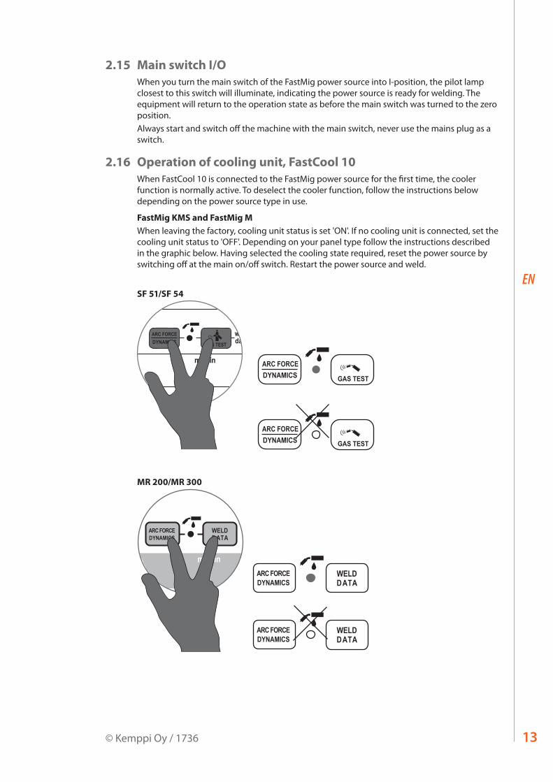
2.16 Operation of cooling unit, FastCool 10When FastCool 10 is connected to the FastMig power source for the first time, the cooler function is normally active. To deselect the cooler function, follow the instructions below depending on the power source type in use.
FastMig KMS and FastMig MWhen leaving the factory, cooling unit status is set 'ON'. If no cooling unit is connected, set the cooling unit status to 'OFF'. Depending on your panel type follow the instructions described in the graphic below. Having selected the cooling state required, reset the power source by switching off at the main on/off switch. Restart the power source and weld.
SF 51/SF 54
WIRE INCH
welddata
VA
m/min
4T
SETUP2T U
MMA
MIGMMA
PANEL
SF 51
W00
1318
DYNAMICSARC FORCE
GAS TEST
GAS TEST
ARC FORCEDYNAMICS
GAS TEST
ARC FORCEDYNAMICS
MR 200/MR 300
13© Kemppi Oy / 1736
EN
SF 52W/SF 53W and MS 200/MS 300
> 5 s
SETUP A + D B WIRE INCHGAS TEST
ch
ch clear
MINILOG
SET
ON
MEMORY
PANEL
SAVESET
quicksetup
welddata
ARC FORCEDYNAMICS
4T
2TSETUP
POWERU
SELECTSYNERGICPROGRAM
MMA
WISE1-MIGMIG
A V
m/minmm
SF 52W
W00
4269MMA PEN
remoteCH
C WIRE INCHGAS TEST
ch
ch clear
MINILOG
SET
ON
MEMORY
PANEL
SAVESET
quicksetup
welddata
ARC FORCEDYNAMICS
4T
2TSETUP
POWERU
SELECTSYNERGICPROGRAM
MMA
WISE1-MIGMIG
A V
m/minmm
W00
4269MMA PEN
remoteCH
SF 52W
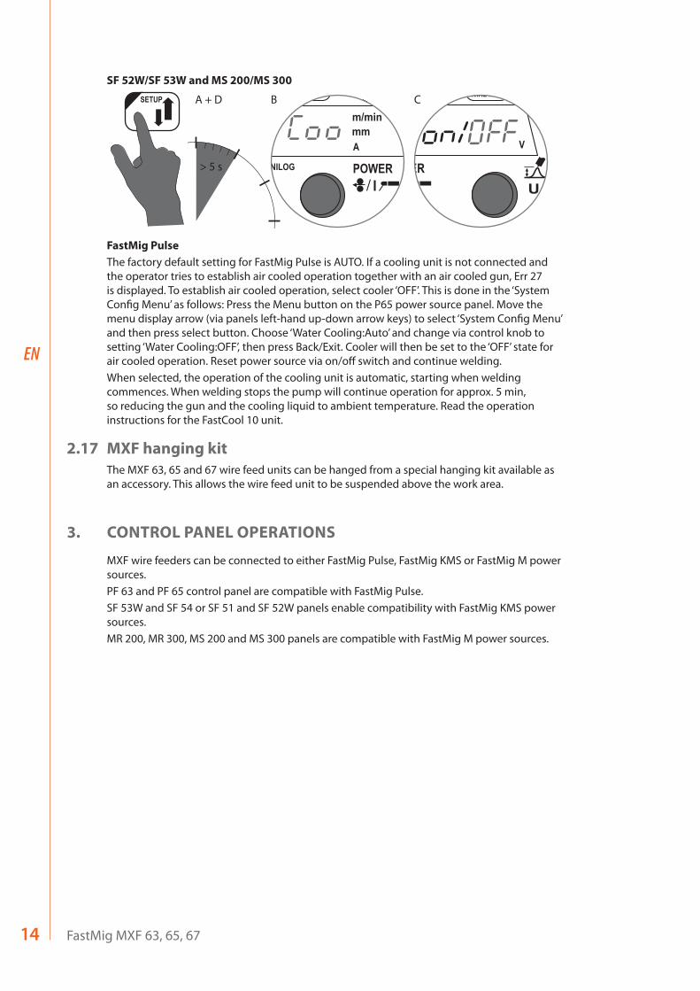
FastMig PulseThe factory default setting for FastMig Pulse is AUTO. If a cooling unit is not connected and the operator tries to establish air cooled operation together with an air cooled gun, Err 27 is displayed. To establish air cooled operation, select cooler ‘OFF’. This is done in the ‘System Config Menu’ as follows: Press the Menu button on the P65 power source panel. Move the menu display arrow (via panels left-hand up-down arrow keys) to select ‘System Config Menu’ and then press select button. Choose ‘Water Cooling:Auto’ and change via control knob to setting ‘Water Cooling:OFF’, then press Back/Exit. Cooler will then be set to the ‘OFF’ state for air cooled operation. Reset power source via on/off switch and continue welding.When selected, the operation of the cooling unit is automatic, starting when welding commences. When welding stops the pump will continue operation for approx. 5 min, so reducing the gun and the cooling liquid to ambient temperature. Read the operation instructions for the FastCool 10 unit.
2.17 MXF hanging kitThe MXF 63, 65 and 67 wire feed units can be hanged from a special hanging kit available as an accessory. This allows the wire feed unit to be suspended above the work area.
3. CONTROL PANEL OPERATIONS
MXF wire feeders can be connected to either FastMig Pulse, FastMig KMS or FastMig M power sources.PF 63 and PF 65 control panel are compatible with FastMig Pulse.SF 53W and SF 54 or SF 51 and SF 52W panels enable compatibility with FastMig KMS power sources.MR 200, MR 300, MS 200 and MS 300 panels are compatible with FastMig M power sources.
FastMig MXF 63, 65, 6714

EN
3.1 Connecting and mounting
Fasten the ribbon cable connector from the MXF wire feed unit to the control panel. Attach the yellow-green earth lead into the fork connector on the PF panel.
MXF 65
1.
2.
1. Place the bottom edge of the panel behind the securing clips on the machine. Remove the fixing pin from the top edge with, for example, a screwdriver. Then gently push the upper part of the panel into place. Make sure that the cables do not get damaged, continue gently pushing the upper part of the panel until it clips into place.
2. Finally secure the panel into place with the additional black plastic security clip provided (MXF 65 only). Ensure that the clip is positioned correctly. You will notice that the clip does not seat snuggly if its positioned upside down.
MXF 63 + MXF 67
MXF 63 MXF 67
+
15© Kemppi Oy / 1736
EN
4. WELDING SOFTWARE DELIVERY PROFILE
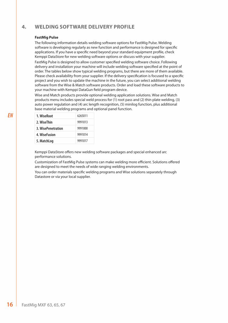
FastMig PulseThe following information details welding software options for FastMig Pulse. Welding software is developing regularly as new function and performance is designed for specific applications. If you have a specific need beyond your standard equipment profile, check Kemppi DataStore for new welding software options or discuss with your supplier.FastMig Pulse is designed to allow customer specified welding software choice. Following delivery and installation your machine will include welding software specified at the point of order. The tables below show typical welding programs, but there are more of them available. Please check availability from your supplier. If the delivery specification is focused to a specific project and you wish to update the machine in the future, you can select additional welding software from the Wise & Match software products. Order and load these software products to your machine with Kemppi DataGun field program device.Wise and Match products provide optional welding application solutions. Wise and Match products menu includes special weld process for (1) root pass and (2) thin plate welding, (3) auto power regulation and (4) arc length recognition, (5) minilog function, plus additional base material welding programs and optional panel function.
1. WiseRoot 6265011
2. WiseThin 9991013
3. WisePenetration 9991000
4. WiseFusion 9991014
5. MatchLog 9991017
Kemppi DataStore offers new welding software packages and special enhanced arc performance solutions.Customization of FastMig Pulse systems can make welding more efficient. Solutions offered are designed to meet the needs of wide ranging welding environments.You can order materials specific welding programs and Wise solutions separately through Datastore or via your local supplier.
FastMig MXF 63, 65, 6716
EN
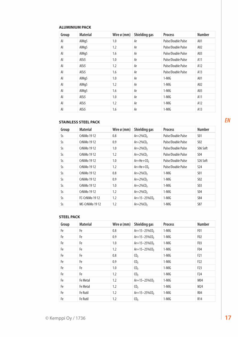
ALUMINIUM PACK
Group Material Wire ø (mm) Shielding gas Process NumberAl AlMg5 1.0 Ar Pulse/Double Pulse A01
Al AlMg5 1.2 Ar Pulse/Double Pulse A02
Al AlMg5 1.6 Ar Pulse/Double Pulse A03
Al AlSi5 1.0 Ar Pulse/Double Pulse A11
Al AlSi5 1.2 Ar Pulse/Double Pulse A12
Al AlSi5 1.6 Ar Pulse/Double Pulse A13
Al AlMg5 1.0 Ar 1-MIG A01
Al AlMg5 1.2 Ar 1-MIG A02
Al AlMg5 1.6 Ar 1-MIG A03
Al AlSi5 1.0 Ar 1-MIG A11
Al AlSi5 1.2 Ar 1-MIG A12
Al AlSi5 1.6 Ar 1-MIG A13
STAINLESS STEEL PACK
Group Material Wire ø (mm) Shielding gas Process NumberSs CrNiMo 19 12 0.8 Ar+2%CO₂ Pulse/Double Pulse S01
Ss CrNiMo 19 12 0.9 Ar+2%CO₂ Pulse/Double Pulse S02
Ss CrNiMo 19 12 1.0 Ar+2%CO₂ Pulse/Double Pulse S06 Soft
Ss CrNiMo 19 12 1.2 Ar+2%CO₂ Pulse/Double Pulse S04
Ss CrNiMo 19 12 1.0 Ar+He+CO₂ Pulse/Double Pulse S26 Soft
Ss CrNiMo 19 12 1.2 Ar+He+CO₂ Pulse/Double Pulse S24
Ss CrNiMo 19 12 0.8 Ar+2%CO₂ 1-MIG S01
Ss CrNiMo 19 12 0.9 Ar+2%CO₂ 1-MIG S02
Ss CrNiMo 19 12 1.0 Ar+2%CO₂ 1-MIG S03
Ss CrNiMo 19 12 1.2 Ar+2%CO₂ 1-MIG S04
Ss FC-CrNiMo 19 12 1.2 Ar+15–25%CO₂ 1-MIG S84
Ss MC-CrNiMo 19 12 1.2 Ar+2%CO₂ 1-MIG S87
STEEL PACK
Group Material Wire ø (mm) Shielding gas Process NumberFe Fe 0.8 Ar+15–25%CO₂ 1-MIG F01
Fe Fe 0.9 Ar+15–25%CO₂ 1-MIG F02
Fe Fe 1.0 Ar+15–25%CO₂ 1-MIG F03
Fe Fe 1.2 Ar+15–25%CO₂ 1-MIG F04
Fe Fe 0.8 CO₂ 1-MIG F21
Fe Fe 0.9 CO₂ 1-MIG F22
Fe Fe 1.0 CO₂ 1-MIG F23
Fe Fe 1.2 CO₂ 1-MIG F24
Fe Fe Metal 1.2 Ar+15–25%CO₂ 1-MIG M04
Fe Fe Metal 1.2 CO₂ 1-MIG M24
Fe Fe Rutil 1.2 Ar+15–25%CO₂ 1-MIG R04
Fe Fe Rutil 1.2 CO₂ 1-MIG R14
17© Kemppi Oy / 1736

EN
WORK PACK
Group Material Wire ø (mm) Shielding gas Process NumberAl AlMg5 1.2 Ar Pulse/Double Pulse A02
Al AlSi5 1.2 Ar Pulse/Double Pulse A12
Fe Fe 1.0 Ar+15–25%CO₂ Pulse/Double Pulse F03
Fe Fe 1.2 Ar+15–25%CO₂ Pulse/Double Pulse F04
Ss CrNiMo 19 12 1.0 Ar+2%CO₂ Pulse/Double Pulse S06
Ss CrNiMo 19 12 1.2 Ar+2%CO₂ Pulse/Double Pulse S04
Al AlMg5 1.2 Ar 1-MIG A02
Al AlSi5 1.2 Ar 1-MIG A12
Fe Fe 0.9 Ar+15–25%CO₂ 1-MIG F02
Fe Fe 1.0 Ar+15–25%CO₂ 1-MIG F03
Fe Fe 1.2 Ar+15–25%CO₂ 1-MIG F04
Fe Fe 0.9 CO₂ 1-MIG F22
Fe Fe 1.0 CO₂ 1-MIG F23
Fe Fe 1.2 CO₂ 1-MIG F24
Fe Fe Metal 1.2 Ar+15–25%CO₂ 1-MIG M04
Fe Fe Metal 1.2 CO₂ 1-MIG M24
Fe Fe Rutil 1.2 Ar+15–25%CO₂ 1-MIG R04
Fe Fe Rutil 1.2 CO₂ 1-MIG R14
Ss CrNiMo 19 12 1.0 Ar+2%CO₂ 1-MIG S03
Ss CrNiMo 19 12 1.2 Ar+2%CO₂ 1-MIG S04
Ss FC-CrNiMo 19 12 1.2 Ar+15–25%CO₂ 1-MIG S84
More welding programs are available by purchasing MatchCurve and MatchCustom products.You can also order welding program packs together with WiseFusion function.
FastMig MXF 63, 65, 6718

EN
5. PANEL BUTTON FUNCTIONS
5.1 PF 63 and PF 65 control panel for FastMig Pulse
W00
3712
PF 65
9. 13.10.11. 12.7.
8.
1. 4.3. 5.2. 6.
1. ON/OFF button2. a) Wire feed speed/welding current display
b) Display of selected adjustable parameter3. a) Activation of MIG welding dynamics / Arc Force adjustment
b) Selection of Wire Feeder (= paralleled wire feeders)4. Gas test 5. Wire inch 6. a) Display of welding voltage /plate thickness /timer settings
b) Display of selected adjustable parameter7. Selection of MIG gun trigger function: 2T/4T/MATCHLOG long press *8. Display of welding process: MIG, 1-MIG, PULSE, DOUBLE PULSE, WISE *9. a) Selection of additional MIG functions
b) Activation of MMA welding process (long press) *10. a) Adjustment of wire feed speed
b) Adjustment of welding power (Synergic 1-MIG and PULSE) c) Adjustment of electrode welding (MMA) current *) d) Adjustment of additional parameters when selected (ie Wire inch, Gas Test)
11. Memory channels 0 – 9, programming through P65 panel on the power source, panel lock (long press on +)
12. a) Adjustment of welding voltage b) Adjustment of length of welding arc (Synergic 1-MIG and PULSE) c) Adjustment of additional parameters when selected (ie MIG Dynamics)
13. Panel control/remote control unit selection, channel remote control (long press)*) Not included in standard delivery. See chapter Ordering numbers
Automatic Weld Data display:Last recorded welding values are displayed post welding. See power source panel P65. Select MENU and then Weld Data.
19© Kemppi Oy / 1736

EN
5.2 PF 63 and PF 65 control panel button functions1. 3.2. 4.
5. 6. 7. 8. 9.
10.
11.
W00
3712
PF 65
5.2.1 ON/OFF button
1.
Short Press: Panel returns to default display.Long Press: When welding panel (PF 65) is ON => Welding panel is turned OFF. When welding panel (PF 65) OFF => welding panel is turned ON and Setup Panel (P65) turns ON and selects automatically that welding panel (WF#).
5.2.2 Dynamics button
2.
Short Press: Dynamics setting if welding process is MIG/Synergic MIG. ArcForce setting if welding process is MMA. Forming Pulse setting if welding process is Wise-Root/WiseThin.Long Press: Wire Feeder number selection (WF#). If more than one wire feeder is connected to system WF number selection must be made. Every wire feeder must be different WF number.
5.2.3 Gas Test button
3.
Gas Test function.Pressing the button will show the gas test time. Gas test time can be adjusted by using the pulse encoder.Gas test will proceed after time adjustment is complete (short delay).Gas test can be stopped by pressing any button.(Gas test can also be started by pressing the Gas Test button inside the wire spool cabinet.)
FastMig MXF 63, 65, 6720

EN
5.2.4 Wire Inch button
4.
Wire Feeder will start immediately when the button is pressed.The default wire inch speed is 5.0m/min.Wire Inch speed can be adjusted (+/-) using the pulse encoder.When the button is released the wire feeder will stop. If the button is pressed again, the wire feeder starts again and slopes to selected wire feed speed (if higher speed is adjusted).(Wire Feeder can also be started by pressing the Wire Inch button inside the wire spool cabinet.)
5.2.5 Channel -
5.
Memory channel down selection.Panel jumps directly to the previous memory channel that can be found from memory.
5.2.6 Channel +
6.
Short Press: Memory channel up selection.Panel jumps directly to next memory channel that can be found from memory.Long Press: Selected memory channel is locked / unlocked. No panel parameter changes allowed to that memory channel (panel lock).
5.2.7 2T/4T button
7.
Gun trigger logic selection.Short Press: 2T / 4T selection.Long Press: MatchLog ON/OFF selection if licence found.
5.2.8 Extra functions button
8.
Short Press: Crater Filling selection / Hot Start Selection.Long Press: MMA ON/OFF selection if licence found.
21© Kemppi Oy / 1736

EN
5.2.9 Remote Selection button
9.
Short Press: Panel /Gun Remote / Hand remote selection. If remote auto recognition is selected ON (see P65 panel menu) only those remote controls which can be found are selected.Long Press: CH remote function ON/OFF. Gun remote or Hand remote control must be first selected before CH remote function can be selected ON/OFF. When active, memory channels are selectable from the remote control device.
5.2.10 Power encoder control knob
10.
The power encoder knob allows adjustment of the wire feed speed or power in either Basic, Synergic and Pulse MIG/MAG process. MMA current level is also adjusted here if the process licence is active. Adjustments can be made before or during the arc process. This control also adjusts additional parameter values when selected.
5.2.11 Arc length/voltage/adjustment control knob
11.
Arc length, voltage and parameter adjustments can be made using this knob. Adjustments can be made before or during welding.
FastMig MXF 63, 65, 6722

EN
5.3 SF 51 and 54 control panel for FastMig KMSFor full operational descriptions for SF 51 and SF 54 control panels refer to the digital storage device delivered with the product.
DYNAMICS WIRE INCHGAS TEST
welddata
ARC FORCE
VA
m/min
4T
SETUP2T U
MMA
MIGMMA
PANEL
SF 51
W00
1318
1. 2. 3. 4. 5. 6. 7.
8.
9. 10. 11. 12. 13.
1. ON/OFF button2. a) Wire feed speed/welding current display
b) Display of selected SETUP entry3. MIG dynamics/MMA Arc Force selection4. Selection of air/liquid cooled MIG gun5. Gas test6. Weld data: Last used welding parameters shown in displays7. Wire inch8. a) Welding voltage display
b) Adjustable parameters display9. Selection of MIG/MMA process10. a) Selection of switching logic: 2T/4T
b) Long press: Setting the basic parameters (SETUP)11. a) Adjustment of wire feed speed
b) Adjustment of MMA current c) Selection of SETUP parameter
12. a) Adjustment of welding voltage b) Adjustment of MIG dynamics or MMA Arc Force c) Adjustment of SETUP parameters
13. Manual control/remote control unit selection
23© Kemppi Oy / 1736

EN
5.4 SF 52W and 53W control panel for FastMig KMSFor full operational descriptions for SF 52W and SF 53W control panels refer to the digital storage device delivered with the product.
WIRE INCHGAS TEST
SET
ON
CH
PANEL
SAVESET
ch clear ch remote
MEMORY
SELECT
quicksetup
welddata
ARC FORCEDYNAMICS
4T
2TSETUP
MMA PEN
MMA
WISE1-MIGMIG
POWERU
SYNERGICPROGRAM
A V
m/minmm
SF 53W
W00
4270
/ MINILOG
1.2. 3. 4. 5. 6. 7.
8.
11.
10.
9.
16.14.12.
13.
15.
1. ON/OFF button2. a) Wire feed speed/welding current/sheet thickness display
b) Selected SETUP entry display3. MIG dynamics/MMA Arc Force/Wise Forming Pulse selection **4. Display of air/liquid cooled MIG gun (selection from setup)5. Gas test6. Weld data: Last used welding parameters shown in displays7. Wire inch8. a) Welding voltage display
b) Selection display for adjustable parameters9. a) 1-MIG/WISE synergic welding program check **
b) 1-MIG/WISE synergic welding program selection (long press) **10. a) Selection of switching logic: 2T/4T/4T Minilog *
b) Long press: Setting the basic parameters (SETUP)11. Selection of welding process MIG,1-MIG, MMA, WISE **12. Selection of additional MIG functions/WisePenetration ** (long press)13. a) Adjustment of wire feed speed
b) Adjustment of welding power setting 1-MIG/WiseRoot/WiseThin ** c) Adjustment of MMA current d) Selection of SETUP parameter e) Selection of 1-MIG/WiseRoot/WiseThin welding program (material group) **
14. Memory channels, storage of MIG parameters15. a) Welding voltage adjustment
b) Adjustment of length of welding arc (1-MIG) c) Adjustment of MIG dynamics d) Adjustment of SETUP parameter e) Selection of 1-MIG/WiseRoot/WiseThin welding program (program number) ** f ) WiseRoot and WiseThin base current adjustment
16. Manual control/remote control unit selection*) Minilog is not included in standard delivery**) Wise products are available as optional welding process solutions. Not included in the standard delivery. Please visit www.kemppi.com or Kemppi Datastore.
FastMig MXF 63, 65, 6724
EN
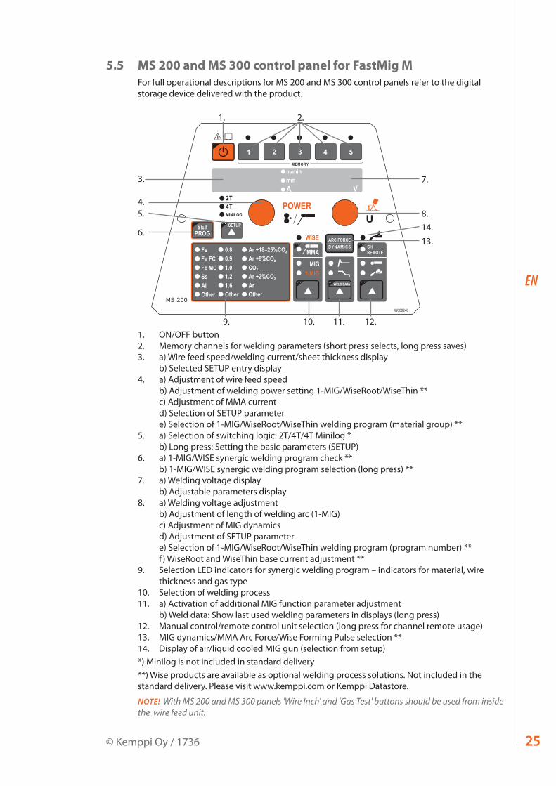
5.5 MS 200 and MS 300 control panel for FastMig MFor full operational descriptions for MS 200 and MS 300 control panels refer to the digital storage device delivered with the product.
1. 2.
9. 10. 11. 12.
4.5.
6.
8.
7.3.
13.14.
1. ON/OFF button2. Memory channels for welding parameters (short press selects, long press saves)3. a) Wire feed speed/welding current/sheet thickness display
b) Selected SETUP entry display4. a) Adjustment of wire feed speed
b) Adjustment of welding power setting 1-MIG/WiseRoot/WiseThin ** c) Adjustment of MMA current d) Selection of SETUP parameter e) Selection of 1-MIG/WiseRoot/WiseThin welding program (material group) **
5. a) Selection of switching logic: 2T/4T/4T Minilog * b) Long press: Setting the basic parameters (SETUP)
6. a) 1-MIG/WISE synergic welding program check ** b) 1-MIG/WISE synergic welding program selection (long press) **
7. a) Welding voltage display b) Adjustable parameters display
8. a) Welding voltage adjustment b) Adjustment of length of welding arc (1-MIG) c) Adjustment of MIG dynamics d) Adjustment of SETUP parameter e) Selection of 1-MIG/WiseRoot/WiseThin welding program (program number) ** f ) WiseRoot and WiseThin base current adjustment **
9. Selection LED indicators for synergic welding program – indicators for material, wire thickness and gas type
10. Selection of welding process11. a) Activation of additional MIG function parameter adjustment
b) Weld data: Show last used welding parameters in displays (long press)12. Manual control/remote control unit selection (long press for channel remote usage)13. MIG dynamics/MMA Arc Force/Wise Forming Pulse selection **14. Display of air/liquid cooled MIG gun (selection from setup)*) Minilog is not included in standard delivery**) Wise products are available as optional welding process solutions. Not included in the standard delivery. Please visit www.kemppi.com or Kemppi Datastore.
NOTE! With MS 200 and MS 300 panels 'Wire Inch' and 'Gas Test' buttons should be used from inside the wire feed unit.
25© Kemppi Oy / 1736

EN
5.6 MR 200 and MR 300 control panel for FastMig MFor full operational descriptions for MR 200 and MR 300 control panels refer to the digital storage device delivered with the product.
1. 2. 3. 4. 5.
6.
7. 8. 9. 10. 11.
1. ON/OFF button2. a) Wire feed speed/welding current display
b) Selected SETUP entry display3. MIG dynamics/MMA Arc Force selection4. Selection of air/liquid cooled MIG gun5. Weld data: Last used welding parameters shown in displays6. a) Welding voltage display
b) Adjustable parameters display7. Selection of MIG/MMA process8. a) Selection of switching logic: 2T/4T
b) Long press: Setting the basic parameters (SETUP)9. a) Adjustment of wire feed speed
b) Adjustment of MMA current c) Selection of SETUP parameter
10. a) Adjustment of welding voltage b) Adjustment of MIG dynamics c) Adjustment of SETUP parameters
11. Manual control/remote control unit selection
NOTE! With MR 200 and MR 300 panels 'Wire Inch' and 'Gas Test' buttons should be used from inside the wire feed unit.
FastMig MXF 63, 65, 6726
EN
6. BASIC TROUBLESHOOTING
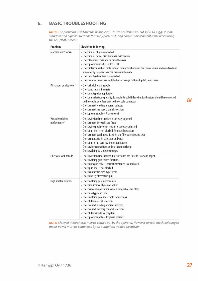
NOTE! The problems listed and the possible causes are not definitive, but serve to suggest some standard and typical situations that may present during normal environmental use when using the MIG/MAG process.
Problem Check the followingMachine won’t work? • Check mains plug is connected
• Check mains power distribution is switched on• Check the mains fuse and or circuit breaker• Check power source 0/I switch is ON• Check interconnection cable set and connectors between the power source and wire feed unit
are correctly fastened. See the manual schematic• Check earth return lead is connected• Check control panels are switched on – Orange buttons top left, long press.
Dirty, poor quality weld? • Check shielding gas supply• Check and set gas flow rate• Check gas type for application• Check gun/electrode polarity. Example: Fe solid filler wire: Earth return should be connected
to the – pole, wire feed unit to the + pole connector • Check correct welding program selected• Check correct memory channel selection• Check power supply – Phase down?
Variable welding performance?
• Check wire feed mechanism is correctly adjusted• Check correct drive rolls are fitted• Check wire spool overrun tension is correctly adjusted• Check gun liner is not blocked. Replace if necessary• Check correct gun liner is fitted for the filler wire size and type• Check contact tip for size, type and wear• Check gun is not over heating in application • Check cable connections and earth return clamp• Check welding parameter settings.
Filler wire won’t feed? • Check wire feed mechanism. Pressure arms are closed? Close and adjust• Check welding gun switch function.• Check euro gun collar is correctly fastened to euro block• Check gun liner is not blocked• Check contact tip, size, type, wear• Check and try alternative gun.
High spatter volume? • Check welding parameter values• Check inductance/Dynamics values• Check cable compensation value if long cables are fitted• Check gas type and flow• Check welding polarity – cable connections• Check filler material selection• Check correct welding program selected• Check correct memory channel selection • Check filler wire delivery system• Check power supply – 3 x phase present?
NOTE! Many of these checks may be carried out by the operator. However certain checks relating to mains power must be completed by an authorised trained electrician.
27© Kemppi Oy / 1736
EN
7. MAINTENANCE
When considering and planning routine maintenance, please consider the frequency of machine use and the working environment. Correct operation of the machine and regular maintenance will help you avoid unnecessary downtime and equipment failure.
NOTE! Disconnect the machine from the mains before handling the electrical cables.
7.1 Daily maintenance• Check the overall condition of the welding gun. Remove welding spatter from the
contact tip and clean the gas nozzle. Replace worn or damaged parts. Only use original Kemppi spare parts.
• Check the condition and connection of the welding circuit components: welding gun, earth return cable and clamp, sockets and connectors.
• Check the condition of the feed rolls, needle bearings and shafts. Clean and lubricate bearings and shafts with a small quantity of light machine oil if necessary. Assemble, adjust and test function.
7.2 Service shop maintenanceKemppi Service Workshops complete maintenance according to their Kemppi service agreement. Recommended termed service and cleaning is listed in the FastMig Pulse Power source manual.Regular preventative maintenance by trained technicians will increase equipment life and ensure reliable operation.
8. DISPOSAL OF THE MACHINE
Do not dispose of electrical equipment with normal waste!In observance of European Directive 2002/96/EC on waste electrical and electronic equipment, and its implementation in accordance with national law, electrical equipment that has reached the end of its life must be collected separately and taken to an appropriate environmentally responsible recycling facility. The owner of the equipment is obliged to deliver a decommissioned unit to a regional collection centre, per the instructions of local authorities or a Kemppi representative. By applying this European Directive you will improve the environment and human health.
FastMig MXF 63, 65, 6728

EN
9. ORDERING NUMBERS
FastMig PulsePF 63 panel 6155200
PF 65 panel 6155100
FastMig Pulse 350, 3 ~ 400V 6150400
FastMig Pulse 450, 3 ~ 400V 6150500
MXF 63 EL wire feeder Work pack profile 6152300EL
MXF 65 EL wire feeder Work pack profile 6152100EL
MXF 67 EL wire feeder Work pack profile 6152200EL
MXF 63 wire feeder Project pack custom 6152300
MXF 65 wire feeder Project pack custom 6152100
MXF 67 wire feeder Project pack custom 6152200
FastMig KMSMXF 63 wire feeder 6152300
MXF 65 wire feeder 6152100
MXF 67 wire feeder 6152200
SF 51 panel, 200 mm 6085100
SF 52W panel, 200 mm 6085200W
SF 53W panel, 300 mm 6085300W
SF 54 panel, 300 mm 6085400
FastMig KMS 300, 3 ~ 400V 6053000
FastMig KMS 400, 3 ~ 400V 6054000
FastMig KMS 500, 3 ~ 400V 6055000
FastMig MMXF 63 EL wire feeder To be used with MS panels 6152300EL
MXF 65 EL wire feeder To be used with MS panels 6152100EL
MXF 67 EL wire feeder To be used with MS panels 6152200EL
MXF 63 wire feeder To be used with MR panels 6152300
MXF 65 wire feeder To be used with MR panels 6152100
MXF 67 wire feeder To be used with MR panels 6152200
FastMig MR 200 panel 6136100
FastMig MR 300 panel 6136200
FastMig MS 200 panel 6136300
FastMig MS 300 panel 6136400
FastMig M 320, 3 ~ 400V 6132320
FastMig M 420, 3 ~ 400V 6132420
FastMig M 520, 3 ~ 400V 6132520
29© Kemppi Oy / 1736

EN
Cooling unit FastCool 10 6068100
Sub feeder synchronisation unit MXF Sync 65
W004030
SuperSnake GT02S sub feeder 10m 6153100
SuperSnake GT02S sub feeder 15m 6153150
SuperSnake GT02S sub feeder 20m 6153200
SuperSnake GT02S sub feeder 25m 6153250
SuperSnake GT02S W sub feeder 10m 6154100
SuperSnake GT02S W sub feeder 15m 6154150
SuperSnake GT02S W sub feeder 20m 6154200
SuperSnake GT02S W sub feeder 25m 6154250
Transport unit PM500 6185291
Transport unit P 501 6185269
Transport unit PM 501 6185292
Transport unit PM 502 6185293
MSF 55 & MXF 65 hanging kit W001694
KFH 1000 hanging device 6185100
KV 200 mounting kit for 2 wire feeders 6185249
Remote control units R20 5 m 6185419
R30 DataRemote 5 m 6185420
R30 DataRemote 10 m 618542001
RMT 10 (for PMT MIG gun) 6185475
FastMig MXF 63, 65, 6730

EN
MIG gunsPMT 35 3 m 6253513
PMT 35 4,5 m 6253514
PMT 42 3 m 6254213
PMT 42 4,5 m 6254214
PMT 50 3 m 6255013
PMT 50 4,5 m 6255014
PMT 30W 3 m 6253043
PMT 30W 4,5 m 6253044
PMT 42W 3 m 6254203
PMT 42W 4,5 m 6254204
PMT 52W 3 m 6255203
PMT 52W 4,5 m 6255204
WS 35 AL 1.2 mm 6 m 6253516A12
WS 30 W AL 1.2 – 1.6 mm 6 m 6253046A12
WS 30 W AL 1.2 – 1.6 mm 8 m 6253048A12
WS 42 W AL 1.2 – 1.6 mm 6 m 6254206A12
WS 42 W AL 1.2 – 1.6 mm 8 m 6254208A12
WS 35 Ss 1.0 mm 6 m 6253516S10
WS 30 W Ss 1.0 mm 6 m 6253046S10
WS 30 W Ss 1.2 mm 6 m 6253046S12
WS 30 W Ss 1.0 mm 8 m 6253048S10
WS 30 W Ss 1.2 mm 8 m 6253048S12
WS 42 W Ss 1.0 mm 6 m 6254206S10
WS 42 W Ss 1.2 mm 6 m 6254206S12
WS 42 W Ss 1.0 mm 8 m 6254208S10
WS 42 W Ss 1.2 mm 8 m 6254208S12
For a complete list of welding guns, please visit Kemppi website at www.kemppi.com.
Interconnection cable 1.8 m 6260401
Interconnection cable 5 m 6260405
Interconnection cable 10 m 6260326
Interconnection cable 15 m 6260325
Interconnection cable 20 m 6260327
Interconnection cable 30 m 6260330
Interconnection cable, water cooled 1.8 m 6260410
Interconnection cable, water cooled 5 m 6260407
Interconnection cable, water cooled 10 m 6260334
Interconnection cable, water cooled 15 m 6260335
Interconnection cable, water cooled 20 m 6260337
Interconnection cable, water cooled 30 m 6260340
Other lengths available
31© Kemppi Oy / 1736

EN
WiseFusion welding function 9991014
WisePenetration welding function 9991000
WiseRoot welding process 6265011
WiseThin welding process 9991013
WiseSynergicMig (for FastMig M) 9990420
MatchLog 9991017
MatchPIN 6265026
MMA welding process (for FastMig Pulse) 9991016
Welding program packages for FastMig PulseWork Pack 99904230
Aluminium Pack 99904231
Steel Pack 99904232
Stainless Steel Pack 99904233
Work Pack + Wise Fusion 99904234
Aluminium Pack + Wise Fusion 99904235
Steel Pack + Wise Fusion 99904236
Stainless Steel Pack + Wise Fusion 99904237
FastMig MXF 63, 65, 6732

EN
10. TECHNICAL DATA
FastMig MXF 63 MXF 65 MXF 67Operating voltage (safety voltage)
50 V DC 50 V DC 50 V DC
Rated power 100 W 100 W 100 W
Output 40 °C 60 % ED 520 A 520 A 520 A
100 % ED 440 A 440 A 440 A
Wire feed speed 0 – 25 m/min 0 – 25 m/min 0 – 25 m/min
Wire feed mechanism 4-roll 4-roll 4-roll
Diameter of feed rolls 32 mm 32 mm 32 mm
Filler wires ø Fe, Ss 0.6 – 1.6 mm 0.6 – 1.6 mm 0.6 – 1.6 mm
ø Cored wire 0.8 – 1.6 mm 0.8 – 2.0 mm 0.8 – 2.0 mm
ø Al 1.0 – 1.6 mm 1.0 – 2.4 mm 1.0 – 2.4 mm
Wire spool max. weight 5 kg 20 kg 20 kg
max. ø 200 mm 300 mm 300 mm
Maximum gas pressure 0.5 MPa 0.5 MPa 0.5 MPa
Gun connection Euro Euro Euro
Operation temperature range -20 ... +40 °C -20 ... +40 °C -20 ... +40 °C
Storage temperature range -40 ... +60 °C -40 ... +60 °C -40 ... +60 °C
EMC class A A A
Degree of protection IP23S IP23S IP23S
External dimensions L x W x H 510 x 200 x 310 mm 620 x 210 x 445 mm 625 x 243 x 476 mm
Weight 9.4 kg 11.1 kg 12.5 kg
33© Kemppi Oy / 1736

www.kemppi.com
1923680 1736
KEMPPI OYKempinkatu 1PL 13FIN-15801 LAHTIFINLANDTel +358 3 899 11Telefax +358 3 899 [email protected]
Kotimaan myynti:Tel +358 3 899 11Telefax +358 3 734 [email protected]
KEMPPI SVERIGE ABBox 717S-194 27 UPPLANDS VÄSBYSVERIGETel +46 8 590 783 00Telefax +46 8 590 823 [email protected]
KEMPPI NORGE A/SPostboks 2151, PostterminalenN-3103 TØNSBERGNORGETel +47 33 346000Telefax +47 33 [email protected]
KEMPPI DANMARK A/SLiterbuen 11DK-2740 SKOVLUNDEDANMARKTel +45 4494 1677Telefax +45 4494 [email protected]
KEMPPI BENELUX B.V.NL-4801 EA BREDANEDERLANDTel +31 765717750Telefax +31 [email protected]
KEMPPI (UK) LTDMartti Kemppi BuildingFraser RoadPriory Business ParkBEDFORD, MK44 3WHUNITED KINGDOMTel +44 (0)845 6444201
Telefax +44 (0)845 [email protected]
KEMPPI FRANCE S.A.S.65 Avenue de la Couronne des Prés78681 EPONE CEDEXFRANCETel +33 1 30 90 04 40Telefax +33 1 30 90 04 [email protected]
KEMPPI GMBHPerchstetten 10D-35428 LANGGÖNSDEUTSCHLANDTel +49 6 403 7792 0Telefax +49 6 403 779 79 [email protected]
KEMPPI SPÓŁKA Z O.O.Ul. Borzymowska 3203-565 WARSZAWAPOLANDTel +48 22 7816162Telefax +48 22 [email protected]
KEMPPI AUSTRALIA PTY LTD13 Cullen PlaceP.O. Box 5256, Greystanes NSW 2145SMITHFIELD NSW 2164 AUSTRALIATel. +61 2 9605 9500Telefax +61 2 9605 [email protected]
OOO KEMPPIPolkovaya str. 1, Building 6127018 MOSCOWRUSSIATel +7 495 240 84 03Telefax +7 495 240 84 [email protected]
ООО КЕМППИул. Полковая 1, строение 6127018 МоскваTel +7 495 240 84 03Telefax +7 495 240 84 [email protected]
KEMPPI WELDING TECHNOLOGY (BEIJING) CO., LTD.Unit 105, 1/F, Building #1, No. 26 Xihuan South Rd.,Beijing Economic-Technological Development Area (BDA),100176 BEIJINGCHINATel +86-10-6787 6064+86-10-6787 1282Telefax +86-10-6787 [email protected]
肯倍焊接技术(北京) 有限公司中国北京经济技术开发区 西环南路26号1号楼1层105室(100176)电话:+86-10-6787 6064/1282传真:+86-10-6787 [email protected]
KEMPPI INDIA PVT LTDLAKSHMI TOWERSNew No. 2/770, First Main Road, Kazura Garden, Neelankarai, CHENNAI - 600 041 TAMIL NADUTel +91-44-4567 1200Telefax +91-44-4567 [email protected]
KEMPPI WELDING SOLUTIONS SDN BHDNo 12A, Jalan TP5A,Taman Perindustrian UEP,47600 Subang Jaya, SELANGOR, MALAYSIATel +60 3 80207035Telefax +60 3 [email protected]