fat hvac, acceptance requirements
TRANSCRIPT
8/13/2019 FAT HVAC, Acceptance Requirements
http://slidepdf.com/reader/full/fat-hvac-acceptance-requirements 1/120
Acceptance Requirements Page 8-1
2005 Nonresidential Compliance Manual March 2005
8. Acceptance Requirements Acceptance requirements ensure that equipment, controls and systems operateas required by the Standards. The activities specified in these requirements
have three aspects:
• Visual inspection of the equipment and installation
• Review of the certification requirements, and
• Functional tests of the systems and controls
Mechanical acceptance requirements are outlined in §121, §122 & §125 of theStandards. Lighting acceptance requirements are outlined in §131. Bothmechanical and lighting acceptance requirements are detailed in Appendix NJ ofthe Non-Residential ACM Manual.
The acceptance process is a way of assuring that the installation was done in away that meets the requirements of the Standards. This process assures notonly that the appropriate equipment was purchased and installed, but that thatequipment is operating properly.
8.1 Overview
Acceptance requirements are defined as the application of targeted inspectionchecks and testing to determine whether specific building systems conform tothe criteria set forth in the Standards and to plans or specifications.
Third party review is not required in the Standards. The Standards permit the Acceptance Agent to be the installing contractor, design professional or anagent selected by the owner. This Acceptance Agent’s role should focus on thefollowing areas:
• Review the bid documents to make sure that sensor locations,devices and control sequences are properly documented,
• Review the installation, perform acceptance tests and documentresults, and
• Document the operating and maintenance information, completeinstallation certificate and indicate test results on the Certificate of
Acceptance, and submit the certificate to the building departmentprior to receiving a final occupancy permit.
Acceptance testing is not intended to take the place of commissioning or testand balance procedures that a building owner might incorporate into a buildingproject. It is an adjunct process focusing only on demonstrating compliance withthe Standards.
This chapter summarizes the requirements for acceptance testing including:
• Section 8.1 Overview provides an overview of roles, responsibilitiesand reasons for the acceptance requirements.

8/13/2019 FAT HVAC, Acceptance Requirements
http://slidepdf.com/reader/full/fat-hvac-acceptance-requirements 2/120
Page 8-2-Acceptance Requirements
2005 Nonresidential Compliance Manual March 2005
• Section 8.2 Acceptance Testing Process discusses how acceptancetesting fits into plan review, construction inspection, system andequipment testing and certification (Certificate of Occupancy).
• Section 8.3 Forms includes a list of forms necessary for completingthe acceptance requirements.
• Section 8.4 Mechanical Acceptance Testing addresses requirementsfor inspecting and testing mechanical systems and equipment.
• Section 8.5 Lighting Acceptance Testing addresses requirements forinspecting and testing lighting systems and equipment.
• Section 8.6 Test Procedures for Mechanical Systems
• Section 8.7 Test Procedures for Lighting Equipment
• Section 8.8 Mechanical Forms for Acceptance Requirements detailsthe compliance forms used to document the mechanical acceptancetesting.
• Section 8.9 Lighting Forms for Acceptance Requirements details the
compliance forms used to document the lighting acceptance testing.
8.1.1 Roles and Responsibilities
The installing contractor, engineer of record or owners agent can act as the Acceptance Agent who shall be responsible for documenting the inspection andtesting results of the acceptance requirement procedures on the AcceptanceTest forms (see Section 8.3 Forms). To make sure that the tests are performed,it is critical that the engineer of record document in the construction documentswho is to perform these tests and the details of the tests to be performed. Thiscould be integrated into the specifications for testing and air balance, energy
management and control system, equipment startup procedures orcommissioning. It is quite possible that the work will be performed by acombination of the Test and Balance (TAB) contractor, mechanical/electricalcontractor and the Energy Management Control System (EMCS) contractor soroles and responsibilities should clearly be called out to get accurate pricing.
A Certificate of Acceptance signed by the Acceptance Agent is required to besubmitted to the building department in order to receive the final Certificate ofOccupancy. Building departments shall not release a final Certificate ofOccupancy unless the submitted Certificate of Acceptance demonstrates thatthe specified systems and equipment have been shown to be performing inaccordance with the Standards. In addition to the Certificate of Acceptance,each test form requires a signature and license number, as appropriate, for the
party who has performed the test. Design professionals and contractors shouldreview the contract provided by the owner to make sure it covers the scope ofthe acceptance testing procedures.
Building officials have authority to require the Acceptance Agent to demonstratecompetence, to the satisfaction of the building official. Building officials shouldplace extra scrutiny on situations where there may be either real or perceivedcompromising of the independence of the Acceptance Agent, and exercise theirauthority to disallow a particular Acceptance Agent from being used in their
8/13/2019 FAT HVAC, Acceptance Requirements
http://slidepdf.com/reader/full/fat-hvac-acceptance-requirements 3/120
Acceptance Requirements Page 8-3
2005 Nonresidential Compliance Manual March 2005
jurisdiction or disallow Acceptance Agent practices that the building officialbelieves will result in compromising of Acceptance Agents independence.
8.1.2 When Are Acceptance Tests Required?
In general the Acceptance Tests apply to new equipment and systems installedin either new construction or retrofit applications. The scope of each test andthe specific exceptions to this rule are noted in the following paragraphs. If anacceptance test is required, the MECH -1-A along with the each specific testmust be submitted to the building department before a final occupancy permitcan be granted.
Mechanical Test Procedures
MECH-2-A: Ventilation System Acceptance Document
• Variable Air Volume Systems Outdoor Air Acceptance
New Construction and Retrofit:
• Applies only to new Variable Air Volume (VAV)systems
• Constant Volume Systems Outdoor Air Acceptance
New Construction and Retrofit:
• Applies only to new Constant Air Volume (CAV)systems
MECH-3-A: Packaged HVAC System Acceptance Document
• Constant Volume Packaged HVAC Systems Acceptance
New Construction and Retrofit:
• Applies only to new single-zone units with directexpansion (DX) cooling. These units may be coolingonly or heating and cooling.
MECH-4-A: Air-Side Economizer Acceptance
• New Construction and Retrofit: All new equipment with air-sideeconomizers must comply. Units with economizers that are installedat the factory and certified with the Commission do not requireequipment testing but do require construction inspection.
MECH-5-A: Air Distribution Acceptance
• New Construction (§144K): Only required for single zone units(heating only, cooling only or heating and cooling) serving 5,000 ft2of space or less where 25% or more of the duct surface area is inone of the following spaces:
• Outdoors, or

8/13/2019 FAT HVAC, Acceptance Requirements
http://slidepdf.com/reader/full/fat-hvac-acceptance-requirements 4/120
Page 8-4-Acceptance Requirements
2005 Nonresidential Compliance Manual March 2005
• In a space directly under a roof where the U-factor of the roof isgreater than the U-factor of the ceiling, or
• In a space directly under a roof with fixed vents or openings to theoutside or unconditioned spaces, or
• In an unconditioned crawlspace; or
• In other unconditioned spaces.
Downshot units with ducts in spaces with insulation on the walls and roof neednot be sealed. Units with extensive ductwork on the roof or in an uninsulatedattic may need to be sealed (it depends on the surface area ratio).
Retrofit: The same scope limitations for zone size, unit type and ductworklocation apply as in new construction. With these constraints, requirements forsealing and testing apply to:
• New ductwork serving either new or existing single-zone units(§149D)
• New ductwork as an extension of existing ductwork with either new
or existing single-zone units, and
• Existing ductwork where the single-zone unit is being replaced orhaving a major component replaced (§149E) including:
• Cooling coil
• Furnace
• Condenser coil (split system) or
• Condensing unit (split system)
Different levels of leakage requirements apply to new and existing ductwork(see §149D).
MECH-6-A: Demand Control Ventilation Acceptance Document
• New Construction and Retrofit: All new DCV controls installed onnew or existing packaged systems must be tested.
MECH-7-A: Supply Fan Variable Flow Controls
• New Construction and Retrofit:
• All new VAV fan volume controls installed on new orexisting systems must be tested.
MECH-8-A: Hydronic System Control Acceptance Document
• Variable Flow Controls
• New Construction and Retrofit:
• Applies to chilled and hot water systems.
• Hydronic System Automatic Isolation Controls
• New Construction and Retrofit:

8/13/2019 FAT HVAC, Acceptance Requirements
http://slidepdf.com/reader/full/fat-hvac-acceptance-requirements 5/120
Acceptance Requirements Page 8-5
2005 Nonresidential Compliance Manual March 2005
• Applies to new boilers and chillers where there is more than oneboiler or chiller in the plant and the primary pumps are connected toa common header.
• Hydronic System Supply Water Temperature Reset Controls
New Construction and Retrofit:
• Applies to new constant flow chilled and hot watersystems that have a design capacity greater than orequal to 500,000 Btu/hr. Note this is not required forsystems that are designed for variable flow.
• Water-loop Heat Pump Controls
• New Construction and Retrofit:
• Applies to all new water-loop heat pump systemswhere the combined loop pumps are greater than 5hp.
• Pump Variable Frequency Drive Control
New Construction and Retrofit:
• Applies to all new distribution pumps on new variableflow chilled, hydronic heat pump or condenser watersystems where the pumps motors are greater than 5hp.
Lighting Test Procedures
All of the lighting acceptance tests apply to new equipment and controlsinstalled on new or existing lighting systems. These tests include:
LTG-2-A: Lighting Control Acceptance Document
• Occupancy Sensor Acceptance
• Manual Daylight Controls Acceptance
• Automatic Time Switch Control Acceptance
LTG-3-A: Automatic Daylight Control Acceptance Document
8.1.3 Why Test for Acceptance?
Building control systems are an integral component of a new building. Fromsimple thermostatic controls and manual light switches to complex buildingautomation systems, controls are an integral part of building health, safety andcomfort. They also are a key component of a building’s energy efficiency. APIER report titled, Integrated Design of Small Commercial HVAC Systems,Element 4, http://www.energy.ca.gov/reports/2003-11-17_500-03-082.PDF found the following problems with package rooftop equipment:
• Economizers. Economizers show a high rate of failure in the study.Of the units equipped with economizers, 64%were not operating

8/13/2019 FAT HVAC, Acceptance Requirements
http://slidepdf.com/reader/full/fat-hvac-acceptance-requirements 6/120
Page 8-6-Acceptance Requirements
2005 Nonresidential Compliance Manual March 2005
correctly. Failure modes included dampers that were stuck orinoperable (38%), sensor or control failure (46%), or poor operation(16%). The average energy impact of inoperable economizers isabout 37% of the annual cooling energy.
• Refrigerant charge. A total of 46% of the units tested were
improperly charged, resulting in reductions in cooling capacity and/orunit efficiency. The average energy impact of refrigerant chargeproblems was about 5% of the annual cooling energy.
• Low airflow. Low airflow was also a common problem. Overall,39% of the units tested had very low airflow rates (< 300 cfm/ton).The average flowrate of all units tested was 325 cfm/ton, which isabout 20% less than the flowrates generally used to rate unitefficiency. Reduced airflow results in reduced unit efficiency andcooling capacity. The annual energy impact of low airflow is about7% of the annual cooling energy.
• Cycling fans. System fans were found to be cycling on and off witha call for heating or cooling in 38% of the units tested. The supply ofcontinuous fresh air during occupied hours relies on continuousoperation of the HVAC unit supply fan.
• Unoccupied fan operation. Fans were also observed to runcontinuously during unoccupied periods in 30% of the systemsobserved. While this practice improves the ventilation of the space, itrepresents an opportunity to save energy through thermostat setbackand fan cycling during unoccupied periods.
• Simultaneous heating and cooling. Adjacent units controlled byindependent thermostats were observed to provide simultaneousheating and cooling to a space in 8% of the units monitored in thestudy. This was largely due to occupant errors in the set up and useof the thermostats, and poor thermostat placement duringconstruction.
• No outdoor air. A physical inspection revealed that about 8% of theunits were not capable of supplying any outdoor air to the spacesserved. In some cases, outdoor air intakes were not provided orwere sealed off at the unit. In other instances, outdoor air damperswere stuck shut, preventing outdoor air intake.
Acceptance testing is a way of assuring that targeted building systems weredesigned, constructed and started up to the intent of the Standards.
8.2 Acceptance Testing Process
The acceptance requirements require four major check-points to be conducted.They are:
• Plan review
• Construction inspection
• Testing

8/13/2019 FAT HVAC, Acceptance Requirements
http://slidepdf.com/reader/full/fat-hvac-acceptance-requirements 7/120
Acceptance Requirements Page 8-7
2005 Nonresidential Compliance Manual March 2005
• Certificate of Occupancy
These will be discussed in more detail below.
8.2.1 Plan Review
The installing contractor, engineer of record or owners agent shall beresponsible for reviewing the plans and specifications to assure they conform tothe acceptance requirements. This is typically done prior to signing a Certificateof Compliance.
In reviewing the plans, the designer will be noting on the MECH-1-C and LTG-1-C code compliance forms, all of the respective mechanical and lighting systemsthat will require acceptance tests. An exhaustive list is required so that thatwhen the acceptance tests are bid, all parties are aware of the scope ofacceptance testing on the project.
8.2.2 Construction InspectionThe installing contractor, engineer of record or owners agent shall beresponsible for performing a construction inspection prior to testing. Reviewingthe acceptance requirements with the contractor prior to installation is veryuseful on several counts.
In some cases, it is most economical to perform testing immediately afterinstallation.
Awareness of the acceptance test may result in the contractor identifying adesign or construction practice that would not comply with the acceptancetesting requirements prior to installation.
Purchasing equipment with calibration certificates reduces the amount ofrequired site calibration and may keep overall costs down.
The purpose of the construction inspection is to assure that the equipment thatis installed is capable of complying with the requirements of the Standards.Construction inspection also assures that the equipment is installed correctlyand is calibrated.
8.2.3 Testing
The installing contractor, engineer of record or owners agent shall beresponsible for undertaking all required acceptance requirement procedures.They shall be responsible for identifying all performance deficiencies, ensuringthat they are corrected and again implementing the acceptance requirementprocedures until all specified systems and equipment are performing inaccordance with the Standards.
The installing contractor, engineer of record or owners agent shall beresponsible for documenting the results of the acceptance requirementprocedures on the acceptance test forms and indicate satisfactory completion bysigning the Certificate of Acceptance.

8/13/2019 FAT HVAC, Acceptance Requirements
http://slidepdf.com/reader/full/fat-hvac-acceptance-requirements 8/120
Page 8-8-Acceptance Requirements
2005 Nonresidential Compliance Manual March 2005
8.2.4 Certificate of Occupancy
Building departments shall not release a final Certificate of Occupancy until aCertificate of Acceptance is submitted that demonstrates that the specifiedsystems and equipment have been shown to be performing in accordance withthe Standards. The installing contractor, engineer of record or owners agent
upon completion of undertaking all required acceptance requirement proceduresshall record their State of California Contractor’s License number or their Stateof California Professional Registration License Number on each Certificate of
Acceptance that they issue.
8.3 Forms
Acceptance tests are documented using a series of forms. These include aCertificate of Acceptance and individual worksheets to assist in field verification.Table 8-1 shows the acceptance forms and reference Standards sections:
Table 8-1 – Acceptance Forms
Section Form Name Standards Reference ACM Manual
AppendixReference
Lighting LTG-1-A Certificate of Acceptance §10-103 N/A
LTG-2-A Lighting Controls §119(d) and §131(d) NJ 6.2, 6.3 and6.4
LTG-3-A Automatic Daylighting §119(e) NJ 6.1
Mechanical MECH-1-A Certificate of Acceptance §10-103 N/A
MECH-2-A Ventilation Systems – Variable andConstant Volume
§121(b)2 NJ 3.1 and 3.2
MECH-3-A Packaged HVAC Systems §121(b)2, §122 NJ 4.1
MECH-4-A Air-Side Economizer §144(e) NJ 7.1
MECH-5-A Air Distribution Systems §144(k) NJ 5.1
MECH-6-A Demand Control Ventilation §121(c)4 NJ 8.1
MECH-7-A Supply Fan VFD §144(c) NJ 9.1
MECH-8-A Hydronic Systems Control §144(j) NJ 10.1 – 10.5
The forms listed above can be found in Appendix A.
8.4 Mechanical Acceptance Testing Overview
8.4.1 Administration
§10-103 (b)
The administrative requirements contained in the Standards require themechanical plans and specifications to contain:
8/13/2019 FAT HVAC, Acceptance Requirements
http://slidepdf.com/reader/full/fat-hvac-acceptance-requirements 9/120
Acceptance Requirements Page 8-9
2005 Nonresidential Compliance Manual March 2005
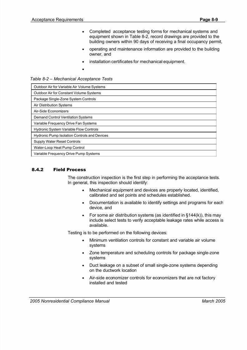
• Completed acceptance testing forms for mechanical systems andequipment shown in Table 8-2, record drawings are provided to thebuilding owners within 90 days of receiving a final occupancy permit,
• operating and maintenance information are provided to the buildingowner, and
• installation certificates for mechanical equipment.
•
Table 8-2 – Mechanical Acceptance Tests
Outdoor Air for Variable Air Volume Systems
Outdoor Air for Constant Volume Systems
Package Single-Zone System Controls
Air Distribution Systems
Air-Side Economizers
Demand Control Ventilation Systems
Variable Frequency Drive Fan Systems
Hydronic System Variable Flow Controls
Hydronic Pump Isolation Controls and Devices
Supply Water Reset Controls
Water-Loop Heat Pump Control
Variable Frequency Drive Pump Systems
8.4.2 Field Process
The construction inspection is the first step in performing the acceptance tests.
In general, this inspection should identify:• Mechanical equipment and devices are properly located, identified,
calibrated and set points and schedules established.
• Documentation is available to identify settings and programs for eachdevice, and
• For some air distribution systems (as identified in §144(k)), this mayinclude select tests to verify acceptable leakage rates while access isavailable.
Testing is to be performed on the following devices:
• Minimum ventilation controls for constant and variable air volume
systems
• Zone temperature and scheduling controls for package single-zonesystems
• Duct leakage on a subset of small single-zone systems dependingon the ductwork location
• Air-side economizer controls for economizers that are not factoryinstalled and tested
8/13/2019 FAT HVAC, Acceptance Requirements
http://slidepdf.com/reader/full/fat-hvac-acceptance-requirements 10/120
Page 8-10-Acceptance Requirements
2005 Nonresidential Compliance Manual March 2005
• Demand control ventilation systems
• Fan volume controls for variable air volume systems
• Variable flow controls for chilled water and hot water systems servingmore than 3 coil control valves.
• Isolation valves on chillers and boilers in plants with more than onechiller or boiler being served by the same primary pumps through acommon header
• Supply water reset controls for constant flow chilled and hot watersystems with a design capacity greater than 500,000 Btu/hr
• Water-loop heat pump isolation valve controls for systems with acombined circulation loop pump horsepower greater than 5 hp
• Variable frequency drive pump systems
8.4.3 Mechanical Acceptance Test Issues
Acceptance testing must be tailored for each specific design, job site, andclimactic conditions. While the steps for conducting each test remain consistent,the application of the tests to a particular site may vary. The following sectiondiscusses some of the known issues that occur when the acceptance tests areapplied to a project.
General Issues
Combining tests to reduce testing costs
Many of the acceptance tests overlap in terms of activities. For example, bothNJ.3.1 Variable Air Volume Systems Outdoor Air Acceptance and NJ.9.1 Supply
Fan Variable Flow Controls Acceptance require that the zone controls beoverridden to force the system into full design flow and low flow conditions.Since the bulk of the time for either test is the process of driving the VAV boxesinto a set position it makes sense to combine these two tests: performing thesuperset of activities with the boxes at both design and part-load conditions.There are a number of places where combining tests will save time. These aresummarized here and described again in the individual test descriptions below.
• Tests that require override of zone controls: NJ.3.1 Variable AirVolume Systems Outdoor Air Acceptance and NJ.9.1 Supply FanVariable Flow Controls Acceptance.
• Tests that require override of the OSA damper: NJ.3.1 Variable Air
Volume Systems Outdoor Air Acceptance (or NJ.3.2 ConstantVolume Systems Outdoor Air Acceptance), NJ.7.1 (Air-Side)Economizer Acceptance, and NJ.8.1 Demand Control Ventilation
Acceptance.
• Tests that require changing the unit mode of operation: NJ.4.1Constant Volume Packaged HVAC Systems Acceptance and NJ.7.1
Air-Side Economizer Acceptance.

8/13/2019 FAT HVAC, Acceptance Requirements
http://slidepdf.com/reader/full/fat-hvac-acceptance-requirements 11/120
Acceptance Requirements Page 8-11
2005 Nonresidential Compliance Manual March 2005
• Tests that require deadheading the circulation pump and overridingcontrol valves: NJ.10.1 Variable Hydronic Flow Controls Acceptance(alternate 2), NJ.10.2 Automatic Isolation Controls Acceptance andNJ.10.4 Water-loop Heat Pump Controls Acceptance (alternate 2),.Note that systems with flow measurement capabilities can usealternate 1 for both NJ.10.1 Variable Hydronic Flow Controls
Acceptance and NJ.10.4 Water-loop Heat Pump Controls Acceptance which do not require deadheading of the pump but dorequire closing control valves.
Internal control delays
Be aware of the potential for delays programmed into many control sequences.The purpose of delays is to prevent the system from controlling too rapidly andbecoming unstable. With delays between five to 30 minutes, the acceptancetesting can be prolonged considerably.
Examples include the normal time that it takes to stroke a damper (typicallyseveral minutes end to end) and anti-recycle timers on refrigerant compressors(typically on the order of 5 to 15 minutes).
Initial conditions
Each test instructs the contractor to return the systems to normal operatingcondition based on the initial schedules, setpoints, and control parameters.These initial settings shall be recorded prior to initiating the testing process.
Obtain correct control sequences before testing
It is essential to know exactly what the control sequences are before testingbegins. Otherwise, the contractor will not be able to customize the test to the
particular systems or verify that the systems work as intended. In many cases,the testing will be performed in conjunction with the controls contractor. Alsomany of these tests can be performed as part of the start-up process.
• Electronic controls are usually documented in the equipment O&Mmanual.
• With pneumatic controls, you need to review the control drawings toascertain how the system is being controlled.
• With DDC controls, it is best to review the control programming thatis currently loaded in the controllers. It is important to note that theactual control logic is often different from the sequences on thedesign plans and specifications for a number of reasons including:
• poorly written or incomplete sequences on the design drawings
• standard practices by the installing EMCS contractor
• issues that arose in the field during control system startup andcommissioning.
Testing based on incorrect sequences will not necessarily yield a valid result.

8/13/2019 FAT HVAC, Acceptance Requirements
http://slidepdf.com/reader/full/fat-hvac-acceptance-requirements 12/120
Page 8-12-Acceptance Requirements
2005 Nonresidential Compliance Manual March 2005
Time to Complete
To give the full picture to contractors, the test summaries below (“At-a-Glance”)include estimates of the time to complete construction observation as well as equipment testing. These estimates are made for a specific test on a specificsystem; they need to be aggregated to estimate the time for completion on the
entire building. These estimates need to be used with caution; times will varydepending on a number of factors including the complexity of the controls, thenumber of control zones, the number of similar tests and other issues. Expectthat the first time a test is performed it will take longer. Subsequent tests willtake less time as tester becomes more experienced and familiar with the test.
8.4.4 Sensor Calibration
A variety of sensors are used to control many facets of heating, ventilating, andair conditioning systems. Confirming that a sensor is measuring the respectiveparameter accurately is crucial to proper system operation and energyperformance. For example, if a supply fan variable frequency drive is controlled
based on duct static pressure, then it is imperative that the pressure sensor ismeasuring accurately. A precise definition of calibration is to perform a set oftest procedures under specific conditions in order to establish a relationshipbetween the value indicated by a measuring device and the correspondingvalues that would be realized by the standard being applied. The most commontesting standards have been developed by the National Institute of Standardsand Technology (NIST). However, the term “calibration” used in the acceptancetests simply refers to verification that the measured value from a sensor willcorrespond reasonably well (within 10% for pressure or light and within 2°F fortemperature) to the actual state of the medium being measured.
The requirement found in a few test procedures for sensor calibration can bemet by either having a calibration certificate provided with the sensor from themanufacturer or through field verification. A calibration certificate from themanufacturer verifies that the particular sensor was tested per a traceablestandard (typically NIST) and confirmed to be measuring accurately. A factory-calibrated sensor is assumed to be accurate and requires no further testing.Field verification generally requires checking the measured value from thesensor against a calibrated instrument while the sensor is installed in thesystem. Typically most sensors can be checked at a single operating point if theexpected measurement range does not vary significantly. Any adjustments thatare necessary to make the field-installed sensor correspond to the valuemeasured by the calibrated instrument can be made at either the transmitteritself or within the control system database.
The following sensors are required to be checked for calibration.• Pressure sensors used in variable flow applications (i.e. supply fan or
pump variable frequency drive is controlled to maintain a specificpressure setpoint). This is applicable to test procedure(s): NJ9.1Supply Fan Variable Flow Controls; NJ10.4 Water-loop Heat PumpControls; and NJ10.5 (Pump) Variable Frequency Drive Controls.
Accuracy to 10%.

8/13/2019 FAT HVAC, Acceptance Requirements
http://slidepdf.com/reader/full/fat-hvac-acceptance-requirements 13/120
Acceptance Requirements Page 8-13
2005 Nonresidential Compliance Manual March 2005
• Temperature sensors used to control field-installed economizers andsupply temperature reset. This is applicable to test procedure(s):NJ7.1 Economizer Acceptance; and NJ10.3 Supply WaterTemperature Reset Controls. Accuracy to 2°F.
• Carbon dioxide sensors used to control outside air dampers. This is
applicable to test procedure(s): NJ8.1 Demand Control Ventilation Acceptance. Accuracy to 75 PPM (parts per million) of CO2 concentration.
• Flow sensors only if used to control outside air dampers. This isapplicable to test procedure(s): NJ3.1 Variable Air Volume SystemsOutdoor Air Acceptance. Overall the system need to be able tocontrol flows to within the 10% of the design outside air value.
Zone temperature sensors or thermostats do not need to be checked forcalibration. Typically if these sensors are out of calibration, zone temperaturesetpoint will most likely be adjusted to accommodate for any variation betweenmeasured and actual values. In order to satisfy the “calibration” requirementoutlined in NJ4.1 Constant Volume Package HVAC Systems Acceptance,simply review manufacturer’s cut sheet.
8.4.5 Air and Water Measurements
Balancing. It is recommended that before an occupancy permit is granted for anew building or space, or a new space-conditioning system serving a building orspace is operated for normal use, the system should be balanced in accordancewith the procedures defined by the Testing Adjusting and Balancing Bureau(TABB) National Standards (2003); the National Environmental BalancingBureau (NEBB) Procedural Standards (1983); or Associated Air BalanceCouncil (AABC) National Standards (1989).
8.4.6 Factory Air-Side Economizer Certification Procedure
When a manufacturer supplies an HVAC unit with a factory-installed economizersection certified to meet California Energy Commission economizer qualitycontrol requirements, the manufacturer shall be responsible for verifying that theunit meets the following acceptance requirements.
Equipment components shall be certified as passing inspections or tests shownin Table 8-3.

8/13/2019 FAT HVAC, Acceptance Requirements
http://slidepdf.com/reader/full/fat-hvac-acceptance-requirements 14/120
Page 8-14-Acceptance Requirements
2005 Nonresidential Compliance Manual March 2005
Table 8-3 – Certification of Air-Side Economizer Components
Component Factory Inspect and/or Test
Outdoor Temperature Sensor orEnthalpy
Enclosure mounted outdoor temperature or enthalpy sensor is calibratedand properly shielded from direct sunlight.
High-Limit Switch Test and verify high-limit switch showing compliance with Standards Table
144-C per §144 (e)3. Air-Side Economizer Controller Test and verify that economizer sequences in an integrated fashion per
§144(e)2B and can modulate up to 100% outside air per §144(e)1A..
In addition to component certification, the equipment shall pass the followingoperational tests:
Step 1: Test the equipment under a simulated cooling load and verify thefollowing:
• Economizer damper modulates open per §144(e)1.A. to maximumposition to satisfy cooling space temperature setpoint.
• Return air damper modulates closed and is completely closed when
economizer damper is 100% open.• Economizer damper is 100% open before mechanical cooling is
enabled.
• Relief fan, or return fan (if integral to the unit) is operating orbarometric relief dampers (if integral to the unit) freely swing open.
• Mechanical cooling is only enabled if cooling space temperaturesetpoint is not met with economizer at 100% open.
Step 2: Continue from Step 1 and disable the economizer using the high-limitswitch. Verify and document the following:
• Economizer damper closes to minimum position.
• Return air damper opens to normal operating position.
• Relief fan, if applicable, shuts off or barometric relief dampers close.Return fan (if applicable) may still operate even when the economizeris disabled.
• Mechanical cooling remains enabled.
For units with economizers that are factory installed and certified operational bythe manufacturer to California Energy Commission economizer quality controlrequirements, the in field economizer acceptance test does not have to beconducted. A copy of the certification certificate must be attached to the MECH-4-A. All pre-test inspection procedures must be completed.
8.4.7 Alternate Test Procedures for Hydronic System Controls Acceptance
It is important to make sure that control valves are selected to be able to shut offfully against the circulating pump pressure. Failure to do so wastes pumpenergy and may also cause systems to perform reheat (or recool) to make upfor valve leakage. When the acceptance tests were first written, they included aprovision that all valve actuators must be reviewed to ensure that they aresufficient to close off against the pump pressure. In a system with hundreds of
8/13/2019 FAT HVAC, Acceptance Requirements
http://slidepdf.com/reader/full/fat-hvac-acceptance-requirements 15/120
Acceptance Requirements Page 8-15
2005 Nonresidential Compliance Manual March 2005
control valves this is both impractical and costly. Alternate 2 of NJ.10.1 VariableHydronic Flow Controls tests all of the valves in a hydronic system at the sametime to demonstrate the control valve ability to shut off flow.
Alternate 1 of the NJ.10.5 (Pump) Variable Frequency Drive Controls Acceptance required measurement of the hydronic flow and drive power both at
full load and 50% flow conditions. This was intended to demonstrate theprovision of §144(j)6 that requires a variable speed drive or equivalent controlthat draws no more than 30% full load power at 50% flow. The purpose of thistest in the Standards is to determine if a control other than a variable speeddrive can meet or exceed the performance of a variable speed drive. If thepumps are controlled by variable speed drives their power and flow do not needto be measured as they generally meet the 30% power at 50% flow provision ifthe hydronic loop control pressure is kept constant or is reduced with reducedflow.. Measuring the control loop pressure at full and low flow in Alternate 2 ofthe NJ.10.5 (Pump) Variable Frequency Drive Controls Acceptance testvalidates that the VFD control is responding correctly.
8.5 Lighting Acceptance Testing Overview
Acceptance requirements can effectively improve code compliance and helpdetermine whether lighting equipment meets operational goals and whether itshould be adjusted to increase efficiency and effectiveness.
8.5.1 Administration
§10-103 (b)
The administrative requirements contained in the Standards require the lighting
plans and specifications to contain:• Completed acceptance testing forms for automatic daylighting
controls, manual daylight switching, occupant sensing devices andautomatic shut-off controls.
• Record drawings are provided to the building owners within 90 daysof receiving a final occupancy permit, ,
• Operating and maintenance information be provided to the buildingowner, and
• Requirement for the issuance of installation certificates fordaylighting controls, occupant sensing devices and automatic shut-
off controls.For example, the plans and specifications would require automatic shut-offlighting controls. A construction inspection would verify the device location andwiring is complete. Acceptance tests would verify proper zoning, on-off functionsand overrides to assure the shut-off system is properly functioning. Owners’manuals and maintenance information would be prepared for delivery to thebuilding owner. Finally, record drawing information, including programminginformation for the automatic shut-off lighting controls must be submitted to thebuilding owner within 90 days of the issuance of a final occupancy permit.

8/13/2019 FAT HVAC, Acceptance Requirements
http://slidepdf.com/reader/full/fat-hvac-acceptance-requirements 16/120
Page 8-16-Acceptance Requirements
2005 Nonresidential Compliance Manual March 2005
8.5.2 Constructability Plan Review
Although acceptance testing does not require a plan review to be performed bythe construction team, the construction team should review the constructiondrawings and specifications to understand the scope of the acceptance testsand raise critical issues that might affect the success of the acceptance tests
prior to starting construction. Any constructability issues associated with thelighting system should be forwarded to the design team so that necessarymodifications can be made prior to equipment procurement and installation. Asan example, understanding the construction inspection requirements for manualor automatic daylighting controls (NJ6.3 and NJ6.1) could prevent expensiverewiring if the circuiting requirements are understood prior to installing thewiring.
8.5.3 Field Process
Construction Inspection
“Do it right the first time.” It is better to check that the wiring plan complies withthe acceptance test requirements before installation. The alternative may resultin the wiring not passing the construction acceptance test and rewiring.
Construction inspection should occur while wiring is installed. If changes haveto be made to circuiting, it is better to do this while a lift is still on site or beforeobstructions are installed.
Key circuiting issues are:
• Wiring for multi-level control. Lamps, luminaires or rows ofluminaires are regularly assigned to different circuits so that lightlevels can be increased uniformly by switching
• Lighting in the daylit zone has to be on separate circuits from otherlighting and, in most cases, must also be wiring for multi-levelcontrol.
Construction inspection should also identify:
• Lighting control devices are properly located, calibrated andsetpoints or schedules established,
• Documentation is available to identify settings and programs for eachdevice, and
Testing is to be performed on the following devices:
• Automatic daylighting controls• Manual daylighting controls
• Occupancy sensing devices, and
• Automatic shut-off controls
8/13/2019 FAT HVAC, Acceptance Requirements
http://slidepdf.com/reader/full/fat-hvac-acceptance-requirements 17/120
Acceptance Requirements Page 8-17
2005 Nonresidential Compliance Manual March 2005
8.5.4 Lighting Acceptance Test Issues
Acceptance testing must be tailored for each specific design, job site, andclimactic conditions. While the steps for conducting each test remain consistent,the application of the tests to a particular site may vary. The following sectiondiscusses some of the known issues that occur when the acceptance tests are
applied to a project.
General Issues
Internal control delays
Be aware of the potential for delays programmed into many control sequences.The purpose of delays is to prevent the system from controlling too rapidly andbecoming unstable. With delays between five to 30 minutes, the acceptancetesting can be prolonged considerably.
Initial conditions
Each test instructs the contractor to return the systems to normal operatingcondition based on the initial schedules, setpoints, and control parameters.These should be recorded prior to initiating the testing process.
Obtain correct control sequences before testing
It is essential to know exactly how the control sequences are programmedbefore testing begins. Otherwise, the contractor will not be able to customize thetest to the particular systems or verify that the systems work as intended.Written control sequences often do not include enough detail to test the systemagainst, or they are found to be incorrect. Testing based on incorrect sequenceswill not necessarily yield a valid result. In addition, to be successful, the
contractor will need to know how to manipulate the control system.
Time to complete
To give the full picture to contractors, the At-a-Glance includes the time tocomplete construction observation as well as equipment testing. In addition, the
At-A-Glance indicates the time shown is per system (not per building).
8.6 Test Procedures for Mechanical Systems
This section includes test and verification procedures for mechanical systemsthat require acceptance testing as listed below:
Use the MECH-2-A for
• NJ.3.1 Variable Air Volume Systems Outdoor Air Acceptance
• NJ.3.2 Constant Volume Systems Outdoor Air Acceptance
Use the MECH-3-A for
• NJ.4.1 Constant Volume Packaged HVAC Systems Acceptance

8/13/2019 FAT HVAC, Acceptance Requirements
http://slidepdf.com/reader/full/fat-hvac-acceptance-requirements 18/120
Page 8-18-Acceptance Requirements
2005 Nonresidential Compliance Manual March 2005
Use the MECH-4-A for
• NJ.7.1 Air-Side Economizer Acceptance
Use the MECH-5-A for
• NJ.5.1 Air Distribution Acceptance
Use the MECH-6-A for
• NJ8.1 Packaged Systems DCV Acceptance
Use the MECH-7-A for
• NJ9.1 Supply Fan Variable Flow Controls
Use the MECH-8-A for
• NJ10.1 Variable Flow Controls
• NJ10.2 Automatic Isolation Controls
• NJ10.3 Supply Water Temperature Reset Controls
• NJ10.4 Water-loop Heat Pump Controls• NJ10.5 Variable Frequency Drive Control
The numbers preceding each test are keyed to the section of the Nonresidential ACM Manual, Appendix NJ where the required test is documented.

8/13/2019 FAT HVAC, Acceptance Requirements
http://slidepdf.com/reader/full/fat-hvac-acceptance-requirements 19/120
Acceptance Requirements Page 8-19
2005 Nonresidential Compliance Manual March 2005
8.6.1 NJ.3.1 Variable Air Volume Systems Outdoor Air Acceptance
At-a-Glance
NJ.3.1 Variable Air Volume Systems Outdoor Air Acceptance
Use Form MECH-2-APurpose of the Test
This test ensures that adequate outside air ventilation is provided through the variable air volume airhandling unit under all operating conditions. The test consists of measuring outside air valves atmaximum flow and at or near minimum flow. The test verifies that the minimum volume of outside air, asrequired per §121(b)2, is introduced to the air handling unit when the system is in occupied mode at anysupply airflow. Note that this test should be performed in conjunction with NJ.9.1 Supply Fan VariableFlow Controls Acceptance test procedures to reduce the overall system testing time. Related acceptancetests for these systems include the following:
• NJ.7.1 (Air-Side) Economizer Acceptance (if applicable)
• NJ.8.1 Demand Control Ventilation Acceptance (if applicable)
• NJ.9.1 Supply Fan Variable Flow Controls Acceptance
Benefits of the Test
Bringing adequate outside air into all spaces promotes good indoor air quality. The Standards requirethat minimum ventilation be provided during all normally occupied times to prevent indoor air qualityproblems.
Variable air volume systems will modulate the total supply airflow to meet varying loads. In systems with afixed minimum position on the outside air (OSA) damper this will lead to variations in OSA as the supplyvolume varies. The minimum OSA needs to be dynamically controlled to provide minimum ventilationthroughout the entire range of supply fan operation. A number of methods are presented in Chapter 4 ofthis manual.
Instrumentation
Performance of this test will require measuring outside airflow. The instrumentation needed to performthe task may include, but is not limited to:
• A means to measure airflow (typically either a velocity pressure probe or hot wireanemometer).
• If the system was installed with an airflow monitoring station (AFMS) on the outsideair, it can be used for the measurements if it has a calibration certificate or is fieldcalibrated.
Test Conditions
To perform the test, it will be necessary to override the normal operation of the controls. Thecontrol system of the air handling unit and variable air volume (VAV) boxes must becomplete, including:
• Supply fan capacity control (typically a variable speed drive )
• Air-Side Economizer control
• Minimum outside air damper control
• VAV box control (including zone thermostats and box minimums)

8/13/2019 FAT HVAC, Acceptance Requirements
http://slidepdf.com/reader/full/fat-hvac-acceptance-requirements 20/120
Page 8-20-Acceptance Requirements
2005 Nonresidential Compliance Manual March 2005
All systems must be installed and ready for system operation, including:
• Duct work
• VAV boxes
• Control sensors (temperature, flow, pressure, etc.)
• Electrical power to air handling unit
• Completion of air handling unit start-up procedures, per manufacturer’srecommendations
Document the initial conditions before overrides or manipulation of the setpoints and schedules. All systems must be returned to normal at the end of the test.
Time to Complete
Construction inspection: 0.5 hours (review of flow station with calibration certificate) to 2 hours (to testcalibration of a damper with a calibrated flow curve)
Equipment testing: 1 to 3 hours (depending on the type of zone control and the number of zones)
Acceptance Criteria
Outside airflow station is calibrated (if applicable)
Calibration curve of outside air vs. outside air damper position, inlet vane signal, or VFD signalwas completed during system TAB procedures.
Measured outside airflow is no less than 90% of the Standards requirement found onMechanical Plan Check document MECH-3-CC-05 at:
• Minimum system airflow or 30% of total design flow, whichever is greater
• Design supply airflow
• If a dedicated minimum ventilation fan exists, the measured CFM deliveredregardless of the speed of the supply fan is within 10% of design minimum outside air
found on Mechanical Plan Check document MECH-3-C column I. Note that thisdesign minimum outside air ventilation rate can be significantly greater than thecalculated minimum outside air to account for building pressurization issues, specialrequirements of the space or the preferences of the owner.
Potential Issues and Cautions
Use caution when performing test during winter months in cold climates. Since outside airflowmust remain constant as supply fan flow is reduced, total supply flow can approach 100%outside air. Be sure that all freeze protection and heating coil controls are functioning beforeperforming test.
Coordinate test procedures with the controls contractor since they may be needed to assist withmanipulation of the BAS to achieve the desired operating conditions.
Ensure economizer control is disabled before performing test.

8/13/2019 FAT HVAC, Acceptance Requirements
http://slidepdf.com/reader/full/fat-hvac-acceptance-requirements 21/120
Acceptance Requirements Page 8-21
2005 Nonresidential Compliance Manual March 2005
8.6.2 Test Procedure: NJ.3.1 Variable Air Volume Systems Outdoor Air
Acceptance, Use MECH-2-A
Construction Inspection
The system was designed to dynamically maintain the minimum OSA
throughout the full range of supply airflow.
If an outside airflow station is part of the system, it is calibrated
If the system relies on a calibrated damper, there is a calibration curve ofoutside air vs. outside air damper position, inlet vane signal, or VFD signal thatis documented in the TAB report.
Attach the calibration certificate to the acceptance test form and check thecalibration certificate box under the “Construction Inspection” section of MECH-2-A.
Checkout Procedure if the System Has a Flow Station Installed
If the manufacturer provides a calibration certificate specifically for the flowstation, this is acceptable. Note this includes traditional airflow monitoringstations with an array of pitot-tubes or hot-wire anemometers and othercalibrated systems to measure flow. There are several manufactured productsthat correlate flow to a damper’s position using a corresponding pressuremeasurement. If the calibration certificate indicates that the damper has beencalibrated across its intended range of operation, this is sufficient. Attach thecalibration certificate to the acceptance test form and check the “Calibrationcertificate” box in the “Construction Inspection” section of MECH-2-A.
If the manufacturer does not provide a calibration certificate specifically for theflow station, then the flow station must be calibrated in the field with thecalibration documented to the satisfaction of the acceptance testing agent.
Methods for field calibration of airflow monitoring stations include:
1. Traverse across the outside air duct to measure duct velocity, measure ductsize, and calculate flow.
2. Measure face velocity at various points across outside air intake, measureintake damper size, and calculate flow.
3. Traverse across the supply and return ducts to calculate flow (outside airflowcan be estimated as the difference between the supply and return flow rates).
4. Measure differential pressure across flow station at test ports and usemanufacturer’s pressure vs. flow curve to determine airflow (least desirablesince not actually measuring flow).
After calibrating the flow station to within 10% of measured flow, check the“Field calibration” box in the “Construction Inspection” section of MECH-2-A.
Checkout Procedure if the System Does Not Have a Flow Station Installed
If the system does not use an airflow monitoring station to directly measureairflow, the Acceptance Agent should review the sequences of operation toensure that the system has been designed for dynamic control of minimum

8/13/2019 FAT HVAC, Acceptance Requirements
http://slidepdf.com/reader/full/fat-hvac-acceptance-requirements 22/120
Page 8-22-Acceptance Requirements
2005 Nonresidential Compliance Manual March 2005
outdoor air and review the installation to make sure that all of the devices thatare part of that sequence are indeed installed.
There are a number of means to dynamically control minimum OSA. A surveyof common methods are presented in Chapter 4 of the Non-Residential User’sManual. After validating that the sequence of control will dynamically control
outside air check the “System is designed to dynamically control minimum OSA”box in the “Construction Inspection” section of MECH-2-A.
Equipment Testing
Step 1: Disable the air-side economizer, if applicable. For systems with anair-side economizer, disabling the economizer will prevent the outside airdamper from modulating during the test due to atmospheric conditions ratherthan supply airflow variations. Disabling the economizer is necessary only if thesystem is in cooling mode and outside air temperature is below the economizerhigh limit setpoint. The economizer can be disabled in a number of waysdepending on the control strategy used to modulate the outside air dampers:
• Use the high limit switch by reducing the setpoint (return air value oroutside air value if a comparative or changeover strategy,respectively, is used) below the current OSA dry-bulb or enthalpymeasurement
• Disable the economizer damper control loop through software if it isa DDC system.
Step 2: Disable the demand control ventilation, if applicable. For systemswith demand control ventilation, this control must be disabled during the test ofthe minimum OSA control as it may interfere with the setpoint for the minimumOSA control. On a multiple zone system, the demand control ventilation willalmost assuredly be provided using a DDC control package. Using the DDCsoftware, the reset signal to the minimum OSA control loop can be set to a fixed
point equal to the design minimum OSA at full occupancy.
Step 3: Drive all VAV boxes to the greater of the minimum airflow or 30%of total design airflow. The intent is to measure outside airflow when thesystem is operating at or near a minimum flow condition. This point is providedalong with the design point to test the minimum OSA control at either end of itscontrol range. If the system has an airflow monitoring station (AFMS) it will testthe accuracy of that AFMS at the lowest velocity, its least accurate point. Thereare a variety of ways to force the VAV boxes to a minimum position dependingon the building automation system capabilities and control strategies used, forexample:
• Override all space temperature setpoints to a wide range (e.g. 60F
heating and 90F cooling) that will force the VAV boxes into thedeadband (may be accomplished by a global command or it mayhave to be done per individual box).
• Command all VAV boxes to minimum flow position (may beaccomplished by a global command or it may have to be done perindividual box).
8/13/2019 FAT HVAC, Acceptance Requirements
http://slidepdf.com/reader/full/fat-hvac-acceptance-requirements 23/120
Acceptance Requirements Page 8-23
2005 Nonresidential Compliance Manual March 2005
• Set maximum flow setpoint to be the same as minimum flow setpoint(may be accomplished by a global command or it may have to bedone per individual box).
In all three cases, you must release or restore the zone or box controls to theirpretest settings after the test is complete.
An alternative method is to manually adjust the VFD until the system airflow is atthe desired condition. If the VAV boxes are in control they will open up as youare doing this, so you need to provide some time (about 5 minutes) to allow thesystem to settle. Be warned that although this is acceptable for testing OSA,this would not meet the requirements of test NJ.9.1 Supply Fan Variable FlowControls Acceptance for testing the stability of the pressure control loop. Thesetwo tests should be done concurrently to minimize cost.
Verify and Document
Measured outside airflow is within 10% of design outside air flowrate found onMechanical Plan Check document MECH-3-C column I. Acceptable methodsfor measuring outside airflow include, but are not limited to the followingtechniques. The recommendations provided earlier for field airflowmeasurement methods apply here.
1. Read the outside airflow value measured by an airflow monitoring station ifone is installed.
2. Traverse across the outside air duct to measure duct velocity, measure ductsize, and calculate flow.
3. Measure face velocity at various points across outside air intake, measureintake damper size, and calculate flow.
4. Traverse across the supply and return ducts to calculate flow (outside airflowcan be estimated as the difference between the supply and return flow rates).
System operation stabilizes within 15 minutes. The intent is to ensure the PIDcontrol loops are tuned properly so that the system does not hunt.
Step 4: Drive all VAV boxes to achieve design airflow. The intent is tomeasure outside airflow when the system is operating at or near full design flowcondition. This typically occurs when all of the VAV boxes are operating atmaximum cooling flow rate. There are a variety of ways to force the VAV boxesto a maximum cooling position depending on the building automation systemcapabilities and control strategies used, for example:
• Override all space temperature setpoints to be below current spaceconditions to force the VAV box into maximum cooling (may beaccomplished by a global command or it may have to be done perindividual box).
• Command all VAV boxes to maximum flow position (may beaccomplished by a global command or it may have to be done perindividual box).
In either case, you must release or restore the zone or box controls to theirpretest settings after the test is complete.

8/13/2019 FAT HVAC, Acceptance Requirements
http://slidepdf.com/reader/full/fat-hvac-acceptance-requirements 24/120
Page 8-24-Acceptance Requirements
2005 Nonresidential Compliance Manual March 2005
Again, we do not recommend simply forcing the supply fan VFD to a maximumspeed since building pressure/return fan/exhaust damper control strategies mayadversely impact overall system and outside airflow rates. It is much better toallow the system to react as intended under “normal” operating conditions.
Verify and Document
Measured outside airflow is within 10% of design outside air flowrate found onMechanical Plan Check document MECH-3-C column I. Acceptable methodsfor measuring outside airflow include, but are not limited to the followingtechniques. The recommendations provided earlier for field airflowmeasurement methods apply here.
1. Read the airflow value measured by the flow station.
2. Traverse across the outside air duct to measure duct velocity, measure ductsize, and calculate flow.
3. Measure face velocity at various points across outside air intake, measureintake damper size, and calculate flow.
4. Traverse across the supply and return ducts to calculate flow (outside airflowcan be estimated as the difference between the supply and return flow rates).
System operation stabilizes within 15 minutes. The intent is to ensure the PIDcontrol loops are tuned properly so that the system does not hunt.
Step 5: Return system back to normal operating condition. Ensure allschedules, setpoints, operating conditions, and control parameters are placedback at their initial conditions. Release any overrides on the economizer ordemand ventilation controls.
Exception to Equipment Testing Procedures
Air handling systems that have a dedicated fan providing ventilation air to theunit would be exempt from measuring ventilation airflow at minimum andmaximum supply airflow conditions. An independent ventilation air fan willdeliver a constant minimum outside air volume to the air handling unitregardless of the speed of the supply fan. Therefore, the only verificationneeded for this system type would be to measure the actual CFM delivered bythe dedicated ventilation air fan.
Verify and Document
Measured outside airflow is within 10% of design outside air flowrate found onMechanical Plan Check document MECH-3-C column I. Acceptable methodsfor measuring outside airflow include, but are not limited to:
• Read the airflow value measured by the flow station.
• Traverse across the outside air duct to measure duct velocity,measure duct size, and calculate flow.
• Measure face velocity at various points across outside air intake,measure intake damper size, and calculate flow.
• Traverse across the supply and return ducts to calculate flow(outside airflow can be estimated as the difference between the

8/13/2019 FAT HVAC, Acceptance Requirements
http://slidepdf.com/reader/full/fat-hvac-acceptance-requirements 25/120

8/13/2019 FAT HVAC, Acceptance Requirements
http://slidepdf.com/reader/full/fat-hvac-acceptance-requirements 26/120

8/13/2019 FAT HVAC, Acceptance Requirements
http://slidepdf.com/reader/full/fat-hvac-acceptance-requirements 27/120
Acceptance Requirements Page 8-27
2005 Nonresidential Compliance Manual March 2005
control package). The economizer control package is responsible formaintaining a minimum ventilation damper position as necessary andwill most likely receive operation signals from either a thermostat orthrough a connection to a central DDC system.
• Large packaged HVAC systems (> 20 tons) will most likely have
either a stand-alone economizer controller/actuator package (forexample, a Honeywell W7459A) or a control package similar to abuilt-up system (i.e. outside and return air dampers controlled by aDDC signal). The stand-alone economizer package may receiveoperation signals from a thermostat, an internal DDC controller, or acentral DDC system. The “built-up” style economizer will most likelybe controlled by an internal DDC controller or a central DDC system.Some large package systems may also have a dedicated outside airdamper/actuator, independent of the economizer control strategy.
• Built-up HVAC system can control the outside and return dampersthrough a single actuator and damper linkages or throughindependent actuators and control signals. The control signals will
most likely come from a central DDC system. Some built-up systemsmay also have a dedicated outside air damper/actuator, independentof the economizer control strategy.
Equipment Testing
Step 1: Disable the air-side economizer, if applicable. For systems with anair-side economizer, disabling the economizer will prevent the outside airdamper from modulating during the test due to atmospheric conditions ratherthan supply airflow variations. Disabling the economizer is necessary only if thesystem is in cooling mode and outside air temperature is below the economizerhigh limit setpoint. The economizer can be disabled in a number of waysdepending on the control strategy used to modulate the outside air dampers:
• Use the high-limit switch by reducing the setpoint (return air value oroutside air value if a comparative or changeover strategy,respectively, is used) below the current OSA dry-bulb or enthalpymeasurement
• Disable the economizer damper control loop through software if it isa DDC system.
Step 2: Disable the demand control ventilation, if applicable. For systemswith demand control ventilation, this control must be disabled during the test ofthe minimum OSA control as it may interfere with the setpoint for the minimumOSA control. On a multiple zone system, the demand control ventilation will
almost assuredly be provided using a DDC control package. Using the DDCsoftware, the reset signal to the minimum OSA control loop can be set to a fixedpoint equal to the design minimum OSA at full occupancy.
Verify and Document
Measured outside airflow is within 10% of design outside air flowrate found onMechanical Plan Check document MECH-3-C column I. Acceptable methodsfor measuring outside airflow include, but are not limited to, the following
8/13/2019 FAT HVAC, Acceptance Requirements
http://slidepdf.com/reader/full/fat-hvac-acceptance-requirements 28/120

8/13/2019 FAT HVAC, Acceptance Requirements
http://slidepdf.com/reader/full/fat-hvac-acceptance-requirements 29/120
Acceptance Requirements Page 8-29
2005 Nonresidential Compliance Manual March 2005
Test Conditions
Packaged unit and thermostat installation and programming must be complete.
HVAC system must be installed and ready for system operation, including completion of all start-upprocedures, per manufacturer’s recommendations.
Document the initial conditions before overrides or manipulation of the setpoints and schedules. Allsystems must be returned to normal at the end of the test.
Time to Complete
Construction inspection: 0.5 to 1 hour (depending on familiarity with thermostat programming)
Equipment test: 1 to 2 hours
Acceptance Criteria
The thermostat is wired to the unit correctly (note this can be inferred from the acceptance tests).
The heating and cooling setpoints and schedules have been programmed into a thermostat or centralDDC system. The heating and cooling setpoints can be adjusted to least 5°F apart.
Acceptance Criteria
The following modes of operation function correctly:
• Occupied heating mode operation: The supply fan operates continuously, allheating stages operate, cooling is not enabled, and the outdoor air damper is atminimum position.
• Occupied operation with no heating or cooling load: The supply fan operatescontinuously, heating or cooling are not enabled, and the outdoor air damper is at
minimum position.• Occupied cooling mode operation without economizer : The supply fan operates
continuously, all cooling stages operate, heating is not enabled, and outside damperis at minimum position.
• Unoccupied operation with no heating or cooling load: The supply fan shuts off,heating or cooling are not enabled, and the outdoor air damper is closed.
• Unoccupied operation with heating load: The supply cycles ON, heating isenabled, cooling is not enabled, and the outdoor air damper is at minimum position.
• Unoccupied cooling mode operation without economizer : The supply cycles ON,cooling is enabled, heating is not enabled, and the outdoor air damper is at minimumposition.
• Override mode: System reverts to occupied mode, the supply fan turns ON forduration of override, heating or cooling is enabled as necessary, outdoor air damperopens to minimum position.

8/13/2019 FAT HVAC, Acceptance Requirements
http://slidepdf.com/reader/full/fat-hvac-acceptance-requirements 30/120
Page 8-30-Acceptance Requirements
2005 Nonresidential Compliance Manual March 2005
Potential Issues and Cautions
• Ensure that the supply fan runs continuously in occupied mode and cyclesappropriately in unoccupied mode. Cycling refers to the supply fan running onlywhen heating or cooling is enabled.
• When testing the manual override, it may be necessary to adjust the length of the
override period to minimize test time. Be sure to reset the override period back to thecorrect length of time.
• Overall test time may be reduced (especially for rooftop HVAC units controlled bythermostats) if two people perform the test - one to manipulate the thermostat whilesomeone else verifies operation at the packaged unit.
• The Standards do not mandate the actual differential between occupied and
unoccupied setpoints, only that the system must be adjustable down to 55°F for
heating and up to 85°F for cooling and that the thermostat can be set for a 5°Fdeadband.
• Setback control is only required for climates where the winter median of extremes isless than or equal to 32°F.
• Setup control is only required for climates where the 0.5% summer design dry-bulbtemperature is greater than or equal to 100°F.
8.6.6 Test Procedure: NJ.4.1 Constant Volume Packaged HVAC Systems
Acceptance, Use Form MECH-3-A
Test Comments
The following acceptance test procedures are applicable to systems controlledby individual thermostats, internal DDC, or central DDC systems. Most of thetests can be performed through simple manipulation of the individual thermostator the DDC system controlling each packaged HVAC unit. Specific details andexamples of how to perform each test are provided below.
Construction Inspection
Thermostat, or temperature sensor, is located within the zone that the HVAC systemserves.
Thermostat is wired to the unit correctly. Note that this can be inferred from theacceptance tests.
1. In particular, ensure that multiple stage terminals (i.e., 1st and 2nd stage
wires) on the thermostat, both cooling and heating stages, are wired to thecorresponding circuits at the unit.
2. Verify that no factory-installed or field-installed jumpers exist across the 1stand 2nd stage cooling terminals at the unit (this will ensure that only theeconomizer can be enabled as the 1st stage of cooling).
3. For heat pump only, verify the “O” terminal on the thermostat is wired to thereversing valve at the unit.
8/13/2019 FAT HVAC, Acceptance Requirements
http://slidepdf.com/reader/full/fat-hvac-acceptance-requirements 31/120
Acceptance Requirements Page 8-31
2005 Nonresidential Compliance Manual March 2005
4. For heat pump only, verify thermostat dip switch or programmable software isset to heat pump.
Thermostat is capable of achieving a 5°F deadband between heating andcooling setpoints.
Setup and setback (unoccupied) setpoints have been enabled (if required).
Occupied, unoccupied, and holiday schedules have been programmed.Schedules are programmed into an individual thermostat or central DDCsystem. Note that some thermostat brands require that the thermostat be in the“program” mode of operation in order for time schedules to be enabled.
Pre-occupancy purge has been programmed per §121(c)2. This is most easilyaccomplished by scheduling the unit to start one hour prior to actual occupancy.
Equipment Testing
The following procedures are applicable to systems controlled by aprogrammable thermostat, internal DDC (packaged systems only), or centralDDC system.
Step 1: Simulate heating load during occupied condition. (Mode A on MECH-3-A form).
• Set “occupied” time schedule to include actual time or adjust time tobe within the “occupied” time schedule (which ever is easier).
• Set heating setpoint above actual space temperature.
Verify and Document
• Supply fan operates continually during occupied condition.
• Ensure all available heating stages operate. This may require raising
the heating setpoint even further so that multiple heating stages canbecome enabled. For example, many programmable thermostatsand DDC control algorithms use time delays and deviation fromsetpoint to enable multiple heating stages. Setting the heatingsetpoint very high should prevent the 1st stage of heat from meetingsetpoint and allow the system adequate time to enable the 2nd or 3rdstages.
• Cooling is not enabled.
• Outside air damper is open to minimum ventilation position (Note:Outdoor ventilation air requirements will be tested under sectionNJ.3.2 Constant Volume System Outdoor Air Acceptance).
Step 2: Simulate dead band operation during occupied condition.(Mode B)
• Set “occupied” time schedule to include actual time or adjust time tobe within the “occupied” time schedule (which ever is easier).
• Adjust heating and cooling setpoints so that actual spacetemperature is between the two values.

8/13/2019 FAT HVAC, Acceptance Requirements
http://slidepdf.com/reader/full/fat-hvac-acceptance-requirements 32/120
Page 8-32-Acceptance Requirements
2005 Nonresidential Compliance Manual March 2005
Verify and Document
• Supply fan operates continually during occupied condition.
• Heating or cooling should not be enabled.
• Outside air damper is open to minimum ventilation position.
Step 3: For systems without an economizer, simulate cooling load during occupiedcondition. Mode F
• Set “occupied” time schedule to include actual time or adjust time tobe within the “occupied” time schedule (which ever is easier).
• Set cooling setpoint below actual space temperature.
Verify and Document
• Supply fan operates continually during occupied condition.
• Ensure all available cooling stages operate. This may require
lowering the cooling setpoint even further so that multiple coolingstages can become enabled. For example, many programmablethermostats and DDC control algorithms use time delays anddeviation from setpoint to enable multiple cooling stages. Setting thecooling setpoint very low should prevent the 1st stage of cooling frommeeting setpoint and allow the system adequate time to enable the2nd stage.
• Heating is not enabled.
• Outside air damper is open to minimum ventilation position.
Step 4: Simulate dead band operation during unoccupied condition.Mode D
• Set “unoccupied” time schedule to include actual time or adjust timeto be within the “unoccupied” time schedule (which ever is easier).
• Ensure actual space temperature is in between unoccupied heatingand cooling setpoints. Adjust each setpoint as necessary to achievedesired control.
Verify and Document
• Supply fan shuts OFF during unoccupied condition.
• Neither heating or cooling is enabled.
• Outside air damper is completely shut.
Step 5: Simulate heating load during unoccupied condition.
Mode C Note: This test is only applicable for all systems in a climate where thedesign winter median of extremes is less than or equal to 32°F( that are notexempt by §122(e)2.A).
• Set “unoccupied” time schedule to include actual time or adjust timeto be within the “unoccupied” time schedule (which ever is easier).

8/13/2019 FAT HVAC, Acceptance Requirements
http://slidepdf.com/reader/full/fat-hvac-acceptance-requirements 33/120
Acceptance Requirements Page 8-33
2005 Nonresidential Compliance Manual March 2005
• Set heating setpoint above actual space temperature.
Verify and Document
• Supply fan cycles on with call for heating.
• Heating is enabled.
• Cooling is not enabled.
Step 6: For systems without an economizer, simulate cooling load during unoccupiedcondition.
Mode G Note: systems with an economizer will be tested for proper systemoperation under a cooling load in section NJ.7.1 Economizer Acceptance. Thistest is only applicable for those systems in a climate where the 0.5% summerdesign dry-bulb temperature is greater than or equal to 100°F (other systemsare exempted by §122(e)2.B).
• Set “unoccupied” time schedule to include actual time or adjust time
to be within the “unoccupied” time schedule (which ever is easier).• Set cooling setpoint above actual space temperature.
Verify and Document
• Supply fan cycles on with call for cooling.
• Heating is not enabled.
• Cooling is enabled.
• Outside air damper.
Step 7: Simulate manual override during unoccupied condition. Mode E
• Set “unoccupied” time schedule to include actual time or adjust timeto be within the “unoccupied” time schedule (which ever is easier).
• Engage the manual override. This could entail pushing an overridebutton, triggering an occupancy sensor, or enabling some other formof override control.
Verify and Document
• System reverts back to an “occupied” condition. For a DDC controlsystem, verify the “active” heating and cooling setpoints correspondto those programmed for the occupied condition. For a
programmable thermostat, the thermostat may display that it is in the“occupied” mode.
• Supply fan turns on and stays on for the duration of the timedoverride period.
• Heating or cooling is enabled as necessary to maintain spacetemperature setpoint. Actual operation of the equipment depends onwhether heating or cooling is needed at the time of the test.

8/13/2019 FAT HVAC, Acceptance Requirements
http://slidepdf.com/reader/full/fat-hvac-acceptance-requirements 34/120
Page 8-34-Acceptance Requirements
2005 Nonresidential Compliance Manual March 2005
• Outside air damper opens to minimum ventilation position andremains open for the duration of the timed override period. If thesystem has an economizer and there is call for cooling during themanual override, then the economizer should be enabled asnecessary.
•
System reverts back to an “unoccupied” condition at the end of thetimed override period. It may be necessary to adjust the length of theoverride period to minimize test time.
Step 8: For systems with an economizer, simulate cooling load during occupiedcondition (Mode H).
• Set “occupied” time schedule to include actual time or adjust time tobe within the “occupied” time schedule (which ever is easier).
• Set cooling setpoint below actual space temperature.
Verify and Document
• Supply fan operates continually during occupied condition.
• Ensure all available cooling stages operate. This may requirelowering the cooling setpoint even further so that multiple coolingstages can become enabled. For example, many programmablethermostats and DDC control algorithms use time delays anddeviation from setpoint to enable multiple cooling stages. Setting thecooling setpoint very low should prevent the 1st stage of cooling frommeeting setpoint and allow the system adequate time to enable the2nd stage.
• Heating is not enabled
• System passes tests for economizer in NJ.7.1 Air-Side EconomizerAcceptance and documented on form MECH-4-A.
Step 9: For systems with an economizer, simulate cooling load during unoccupiedcondition (Mode I).
• Set “unoccupied” time schedule to include actual time or adjust timeto be within the “unoccupied” time schedule (which ever is easier).
• Set cooling setpoint above actual space temperature.
Verify and Document
• Supply fan cycles on with call for cooling.
• Heating is not enabled.
• Cooling is enabled.
• Outside air damper is closed.
• System passes tests for economizer in NJ.7.1 Air-Side EconomizerAcceptance and documented on form MECH-4-A.
8/13/2019 FAT HVAC, Acceptance Requirements
http://slidepdf.com/reader/full/fat-hvac-acceptance-requirements 35/120
Acceptance Requirements Page 8-35
2005 Nonresidential Compliance Manual March 2005
Step 10: Return system back to normal operating condition.
Ensure all schedules, setpoints, operating conditions, and control parametersare placed back at their initial conditions.
8.6.7 NJ.7.1 Air-Side Economizer Acceptance At-a-Glance
NJ.7.1 (Air-Side) Economizer Acceptance
Use Form MECH-4-APurpose of the Test
The purpose of functionally testing an air-side economizer cycle is to verify that an HVAC system usesoutside air to satisfy space cooling loads when outside air conditions are acceptable. There are twotypes of economizer controls:
• stand-alone packages and DDC controls. The stand-alone packages are commonlyassociated with rooftop packaged HVAC equipment and DDC controls are typicallyassociated with built-up or large packaged air handling systems. Test procedures forboth economizer control types are provided.
For units with economizers that are factory installed and certified operational by the manufacturer toCalifornia Energy Commission economizer quality control requirements, the in field economizeracceptance test does not have to be conducted. A copy of the certification certificate must be attached tothe MECH-4-A. All pre-test inspections must be completed regardless of whether the economizer isfactory or field installed.
Benefits of the Test
Ensuring that the economizer fully utilizes outside air for “free cooling” can save significant cooling energycompared to operating mechanical refrigeration.
Provision and control of building relief prevents building over pressurization which is a common reasonfor economizers being disabled by building operators.
Since an economizer cycle will bring in outdoor air beyond what is required for ventilation purposes, it willimprove building indoor air quality.
Instrumentation
None required

8/13/2019 FAT HVAC, Acceptance Requirements
http://slidepdf.com/reader/full/fat-hvac-acceptance-requirements 36/120
Page 8-36-Acceptance Requirements
2005 Nonresidential Compliance Manual March 2005
Test Conditions
Equipment installation is complete (including HVAC unit, duct work, sensors, control system,thermostats).
Simple systems are required to have a two-stage thermostat.
HVAC system must be ready for system operation, including completion of all start-up procedures permanufacturer’s recommendations.
For those units having DDC controls, it may be necessary to use the building automation system (BAS) tooverride or temporarily modify the variable(s) to achieve the desired control. BAS programming for theeconomizer, cooling valve control, and related safeties must be complete.
For built-up systems all interlocks and safeties must be operable--for example, freeze protection, limitswitches, static pressure cut-out, etc.
Document the initial conditions before overrides or manipulation of the settings. All systems must bereturned to normal at the end of the test.
Time to Complete
Construction Inspection: 0.5 to 1 hours (depending on familiarity with the controls)
Equipment Testing: 0.5 to 2 hours (depending on familiarity with the controls and issues that arise duringtesting)
Acceptance Criteria
If the economizer is factory installed and certified, a valid factory certificate is required for acceptance.No additional equipment tests are necessary.
Air-Side Economizer lockout setpoint complies with Table 144-C per Standards Section 144(e)3. Outsidesensor location accurately reads true outdoor air temperature and is not affected by exhaust air or otherheat sources.
All sensors are located appropriately to achieve the desired control.
During economizer mode, the outside air damper modulates open to a maximum position and return airdamper modulates 100% closed.
The outside air damper is 100% open before mechanical cooling is enabled and for units 75,000 Btuh andlarger remains at 100% open while mechanical cooling is enabled (economizer integration when used forcompliance).
When the economizer is disabled, the outside air damper closes to a minimum position, the return
damper modulates 100% open, and mechanical cooling remains enabled.

8/13/2019 FAT HVAC, Acceptance Requirements
http://slidepdf.com/reader/full/fat-hvac-acceptance-requirements 37/120
Acceptance Requirements Page 8-37
2005 Nonresidential Compliance Manual March 2005
Potential Issues and Cautions
If conditions are below freezing when test is performed, coil(s) may freeze when operating at100% outside air.
Outdoor air and relief dampers should be closed when the system is in unoccupied and warm-up modes, preventing problems with unconditioned air entering the building duringunoccupied hours.
If the damper interlocks fail and the outdoor air damper does not open before the return dampercloses, damage to the air handling unit or associated duct work may occur.
Air-Side Economizers with poor mixing can have excessively stratified air streams that cancause comfort problems or freezestat trips. Mixing problems are more likely to occur as theVAV system reduces flow, leading to reduced velocities in the mixing box and through thedampers.
Check for exterior doors standing open and other signs of building over-pressurization when allunits are on full economizer cooling (100% OSA).
8.6.8 Test Procedure: NJ.7.1 Air-Side Economizer Acceptance,
Use Form MECH-4-A
Purpose (Intent) of Test
There are basically two types of economizer controls: 1) stand-alone packages(i.e. Honeywell W7459A, Trane Precedent or Voyager, Carrier Durablade, whichare most common); and 2) DDC controls. The stand-alone packages are mostcommonly associated with rooftop packaged HVAC equipment and DDCcontrols are typically associated with built-up or large packaged air handling
systems. Test procedures for both economizer control types have beendeveloped and a brief description of each control strategy is provided below.
If the economizer is factory installed and certified by the manufacturer to theCalifornia Energy Commission, no field testing is required.
The typical economizer control will have the following components: a controller(stand alone or DDC); an actuator that will drive both outside and return airdampers (sometimes separate actuators in built-up systems); an outside airsensor; a return air sensor where differential high-limit controls are used; and amixed/discharge air temperature sensor to which the economizer is controlled.The sensor types used to measure outside and return air include dry-bulbtemperature sensors, enthalpy sensors, and electronic enthalpy sensors (a
combination of dry-bulb and enthalpy).In general, a first-stage call for cooling from the zone thermostat will enable theeconomizer controller, which will either allow the outside air damper to open fullyif outside air conditions are suitable or enable the compressor. The fourstrategies available for economizer control are: 1) fixed dry-bulb; 2) fixedenthalpy; 3) differential dry-bulb; and 4) differential enthalpy. The fixed dry-bulband enthalpy strategies both compare outside air conditions to a “fixed” setpointto determine if the economizer can be enabled, whereas differential dry-bulband enthalpy strategies compares outside air and return air conditions to enable
8/13/2019 FAT HVAC, Acceptance Requirements
http://slidepdf.com/reader/full/fat-hvac-acceptance-requirements 38/120

8/13/2019 FAT HVAC, Acceptance Requirements
http://slidepdf.com/reader/full/fat-hvac-acceptance-requirements 39/120
Acceptance Requirements Page 8-39
2005 Nonresidential Compliance Manual March 2005
Table 8-4 – Standards Table 144-C Air Economizer High Limit Shut Off Control Requirements
Device Type Climate Zones Required High Limit (Economizer Off When):
Equation Description
Fixed Dry Bulb 1, 2, 3, 5, 11, 13, 14, 15 & 16 TOA > 75ºF Outside air temperatureexceeds 75ºF
4, 6, 7, 8, 9, 10 & 12 TOA > 70ºF Outside air temperatureexceeds 70°F
Differential Dry Bulb All TOA > TRA Outside air temperatureexceeds return air
temperature
Fixed Enthalpya 4, 6, 7, 8, 9, 10 & 12 hOA > 28 Btu/lb
b Outside air enthalpy exceeds
28 Btu/lb of dry air b
Electronic Enthalpy All (TOA, RHOA) > A Outside air temperature/RHexceeds the "A" set-point
curvec
Differential Enthalpy All hOA > hRA Outside air enthalpy exceedsreturn air enthalpy
a Fixed Enthalpy Controls are prohibited in climate zones 1, 2, 3, 5, 11, 13, 14, 15 & 16.b At altitudes substantially different than sea level, the Fixed Enthalpy limit value shall be set to the enthalpy value at75 F and 50% relative humidity. As an example, at approximately 6000 foot elevation the fixed enthalpy limit isapproximately 30.7 Btu/lb.
c Set point "A" corresponds to a curve on the psychometric chart that goes through a point at approximately 75 Fand 40% relative humidity and is nearly parallel to dry bulb lines at low humidity levels and nearly parallel to enthalpylines at high humidity levels.
• For stand-alone packages only, verify that a two-stage thermostat isused, and that the system is wired so that the economizer is the firststage of cooling and the compressor is the second stage. The two-stage space thermostat must have wires connected to Y1 and Y2 on
the thermostat landed on the respective Y1 and Y2 terminals at theunit. There should not be any jumpers installed across Y1 and Y2 atthe thermostat or the unit. For York units in particular, verify that the“J1” jumper located on the OEM board has been removed. The unitscome from the factory with the “J1” jumper installed and must beremoved in the field (the “J1” jumper is the same as having a jumperacross the Y1 and Y2 terminals – the compressor and economizercome on simultaneously on a call for cooling, which effectively makesthe economizer inoperable). Note that if a single-stage thermostat isinstalled, there should not be any jumper between Y1 and Y2.
• Air-Side Economizer outside (lockout) sensor location is adequate to
achieve the desired control. Outside air sensors should be locatedaway from building exhausts and other heat sources like air-cooledcondensers and cooling towers; should be open to the air but notexposed to direct sunlight (unless it is provided with a radiationshield); and could be located either directly in the air stream orremote from the unit (for example mounted on a north-facing wall).
• Ensure all systems have some method of relief to prevent overpressurization of the building. Most packaged HVAC units withstand-alone economizer controls will typically have barometric

8/13/2019 FAT HVAC, Acceptance Requirements
http://slidepdf.com/reader/full/fat-hvac-acceptance-requirements 40/120
Page 8-40-Acceptance Requirements
2005 Nonresidential Compliance Manual March 2005
dampers to exhaust the return air when the return dampers are fullyclosed and the unit is in economizer mode. Built-up and largerpackaged air handling units may control return fans, relief dampers,or dedicated relief fans to actively maintain building pressurizationwhen the unit is in economizer mode.
Equipment Testing
Since the test procedures vary significantly between stand-alone packages andDDC controls, the procedures for each system type are provided. In addition,there can be significant differences in test procedures between various stand-alone packages themselves. Contact your equipment supplier to see if theyhave equipment and test protocols that will allow you to easily field test theireconomizer to ACM NJ.7.1 Air-Side Economizer Acceptance for filling out formMECH-4-A. While it would not be feasible to cover every variation, three of themost common stand-alone packages are discussed below. The commonfeature of these procedures is that they all exercise the economizer functioneither by enabling an on-board diagnostic function or by “fooling” the control byinserting resistors that simulate mild weather conditions while the system is incooling mode.
Stand-alone Package
Trane Voyager and Precedent Series. Both of these control packages haveinternal test sequences that can be used to verify proper system operation.Each operating mode is enabled by providing a momentary (2 second) jumpacross the test terminals.
Step 1. Use internal test sequences to enable operating modes.
Refer to manufacturer’s literature for detailed description of the procedures,however the basic steps are outlined below:
• 1st jumper – supply fan is enabled
• 2nd jumper – economizer mode is enabled
• 3rd jumper – compressor is enabled
• 4th jumper – heating stage is enabled
Verify and Document
• Outside air damper is at minimum position when the supply fan isenabled.
• The outside air damper opens completely and the return dampercloses completely during economizer mode.
• Outside air damper is at minimum position when the compressor isenabled.
• Outside air damper is at minimum position when heating is enabled.
• Verify the mixed/discharge cut-out sensor wire is landed on the SAterminal on the OEM board. If the sensor wire is not landed on theSA terminal, the economizer will not operate.

8/13/2019 FAT HVAC, Acceptance Requirements
http://slidepdf.com/reader/full/fat-hvac-acceptance-requirements 41/120
Acceptance Requirements Page 8-41
2005 Nonresidential Compliance Manual March 2005
Step 2. Return system to normal operation.
Taking the system out of test mode can be accomplished by shutting power offto the unit. The unit will return to normal operation when power is restored.
Verify and Document
• Final economizer changeover dip-switch settings comply withStandards Table 144-C per §144(e)3.
Honeywell controllers. There are many Honeywell controllers available, butthe most common is the W7459A series and most of the procedures used tocheck out this controller can be used on the others as well (always refer tomanufacturer’s literature for additional information). All Honeywell controllershave an adjustment pot with “A, B, C, D” settings. For a fixed changeoverstrategy, the position of the adjustment pot with respect to the A, B, C, Dsettings will determine the economizer lockout setpoint. For a differentialchangeover strategy, the controller should be on the “D” setting. Note that thecontrollers typically come from the factory with the adjustment pot at the “D”
setting, but this does not mean a differential control strategy is being used. Theeasiest way to verify a differential changeover strategy is to look at the SR and +terminals on the controller. If standard sensor wires are connected to theterminals, then it is a differential control strategy. If there is a 620 Ohm resister
jumpered across these terminals, then a fixed control strategy is being used.
Step 1. Simulate a cooling load and enable the economizer.
The simplest way to determine if the controller is functioning is to:
• Turn the unit OFF at the disconnect.
• Install a 1.2K Ohm resister across the SO and + terminals on thecontroller (this is the outside air temperature sensor).
• Install a 620 Ohm resister across the SR and + terminals on thecontroller (this resister is already installed for a fixed control strategyand must only be installed if there is a return air sensor).
• Turn the economizer setpoint adjustment pot all the way to the “A”setting.
• Install a jumper across the R and Y1 terminals at the unit terminalstrip.
• Disconnect the wire from the Y2 terminal at the unit terminal strip(this will prevent the 2nd stage of cooling from being enabled duringthe test).
• Turn the unit back ON at the disconnect.
Verify and Document
• Outside air dampers open fully. Adjust linkages, if necessary, toensure dampers are at the desired position.
• Return air dampers close completely. Adjust linkages, if necessary,to ensure dampers are at the desired position.

8/13/2019 FAT HVAC, Acceptance Requirements
http://slidepdf.com/reader/full/fat-hvac-acceptance-requirements 42/120
Page 8-42-Acceptance Requirements
2005 Nonresidential Compliance Manual March 2005
• Compressor does not run.
Step 2. Simulate a cooling load and disable the economizer.
Continuing from above:
• Turn the unit OFF at the disconnect.
• Leave the 1.2K Ohm resister across the SO and + terminals and 620Ohm resister across the SR and + terminals in place.
• Turn the economizer setpoint adjustment pot all the way to the “D”setting.
• Leave jumper across the R and Y1 terminals at the unit terminal strip.
• Leave Y2 disconnected.
• Turn the unit back ON at the disconnect.
Verify and Document
• Outside air dampers close to minimum position. Adjust linkages, ifnecessary, to ensure dampers are at the desired position.
• Return air dampers open completely. Adjust linkages, if necessary, toensure dampers are at the desired position.
• Compressor operates.
Step 3: Return system back to normal operating condition.
Remove all jumpers and reconnect all wires.
Verify and Document
• Final economizer changeover setting (A,B,C,D) complies withStandards Table 144-C per §144(e)3. Consult with manufacturer’sliterature to determine the appropriate A, B, C, D setting for bothfixed dry-bulb or enthalpy control strategies. The controller must beset on “D” for all differential control strategies.
Carrier Durablade. Most Carrier HVAC units utilize the “Durablade”economizer control package, which uses a single damper “blade” that slides ona worm gear across both the outside and return air streams. Blade position isdetermined by end-switches that will cut power to the drive-motor when desireddamper position is reached. Typically the economizer will be controlled byeither a fixed dry-bulb or fixed enthalpy control strategy. Enthalpy control
typically utilizes a customized Honeywell controller and the checkout proceduresoutlined above can be used to determine economizer functionality. Thefollowing test procedures should be followed for a fixed dry-bulb strategy.
Step 1. Simulate a cooling load and enable the economizer.
The simplest way to determine if the economizer is functioning is to:
• Turn the unit OFF at the disconnect.
• Install a jumper across the outside air temperature thermostat.

8/13/2019 FAT HVAC, Acceptance Requirements
http://slidepdf.com/reader/full/fat-hvac-acceptance-requirements 43/120
Acceptance Requirements Page 8-43
2005 Nonresidential Compliance Manual March 2005
• Install a jumper across the R and Y1 terminals at the unit terminalstrip.
• Disconnect the wire from the Y2 terminal at the unit terminal strip(this will prevent the 2nd stage of cooling from being enabled duringthe test).
• Turn the unit back ON at the disconnect.
Verify and Document
• Damper blade slides completely across the return air duct and mixedair plenum is open to the outside air intake. Adjust end-switches asnecessary to achieve the desired position.
• Compressor does not run.
Step 2. Simulate a cooling load and disable the economizer.
Continuing from above:
• Turn the unit OFF at the disconnect.
• Remove the jumper and disconnect the outside air sensor completelyfrom the circuit.
• Leave Y2 disconnected.
• Turn the unit back ON at the disconnect.
Verify and Document
• Damper blade returns to minimum outside air position. Adjust endswitches as necessary to achieve the desired position.
• Compressor operates.
Step 3: Return system back to normal operating condition.
Remove all jumpers and reconnect all wires.
Verify and Document
• Final economizer changeover setting complies with Standards Table144-C per §144(e)3.
DDC Controls
Step 1. Simulate a cooling load and enable the economizer.
Simulating a cooling load and enabling the economizer can be accomplished by:
• Commanding the discharge air temperature setpoint to be lower thancurrent discharge conditions.
• For a fixed dry-bulb or enthalpy control strategy, raising theeconomizer lockout setpoint to be above current outside airconditions (if this is not the case already) to enable the economizer.
8/13/2019 FAT HVAC, Acceptance Requirements
http://slidepdf.com/reader/full/fat-hvac-acceptance-requirements 44/120
Page 8-44-Acceptance Requirements
2005 Nonresidential Compliance Manual March 2005
• For a differential dry-bulb or enthalpy control strategy; raising thereturn air conditions to be above current outside air conditions (if thisis not the case already) to enable the economizer.
Verify and Document
• Outside air damper modulates open to a maximum position.
• Return air damper modulates closed and is 100% closed when theoutside air dampers are 100% open. Return dampers should closetight to minimize leakage.
• Outside air damper is 100% open before mechanical cooling isenabled. This implies that cooling coil valves in chilled watersystems should not modulate or compressors in DX systems shouldnot start until the unit is in 100% economizer mode. Depending onthe speed of the PID loop, it is possible that mechanical coolingcould be commanded on before the outside air dampers actuallystroke fully open. If this occurs, it does not mean the system has
failed the test. One option is to watch the output of the PID loop andverify that the COMMAND sent to the outside air damper reaches100% before a command is sent to the mechanical cooling devices.
• Although space pressurization requirements are not part of thecurrent Standards, most systems employ some form of controlstrategy to maintain space pressure during economizer mode.Control strategies can include, but are not limited to: 1) return fanspeed control; 2) dedicated relief fans; or 3) relief damper controls.Observe that the space served by the air handling unit being testeddoes not appear to experience any pressurization problems (i.e.,perimeter doors pushed open or excessive airflow between zonesserved by different units).
Step 2. Simulate a cooling load and disable the economizer.
Continuing from the procedures outlined in Step 1:
• Keep the discharge air temperature setpoint lower than currentdischarge conditions.
• For a fixed dry-bulb or enthalpy control strategy, lower theeconomizer lockout setpoint to be below current outside airconditions (if this is not the case already) to disable the economizer.
• For a differential dry-bulb or enthalpy control strategy; lower thereturn air conditions to be below current outside air conditions (if this
is not the case already) to disable the economizer.
Verify and Document
• Outside air damper closes to a minimum position.
• Return air damper opens to normal operating position when thesystem is not in economizer mode.

8/13/2019 FAT HVAC, Acceptance Requirements
http://slidepdf.com/reader/full/fat-hvac-acceptance-requirements 45/120

8/13/2019 FAT HVAC, Acceptance Requirements
http://slidepdf.com/reader/full/fat-hvac-acceptance-requirements 46/120
Page 8-46-Acceptance Requirements
2005 Nonresidential Compliance Manual March 2005
8.6.9 NJ.5.1 Air Distribution Acceptance
At-a-Glance
NJ.5.1 Air Distribution Acceptance
Use Form MECH-5-APurpose of the Test
The purpose of this test is to verify all duct work associated with all non-exempt constant volume, single-zone, HVAC units (i.e. air conditioners, heat pumps, and furnaces) meet the material, installation, andinsulation R-values per §124(a) requirements of §144(k), including construction materials, installation,insulation R-values, and that duct leakage does not exceed the maximum allowable leakage fraction per§144(k) for new duct systems or §149(b)1D for existing duct systems.
As detailed in the Standard this test is only required for single-zone units serving 5,000 ft2 of space or
less where 25% or more of the duct surface area is in one of the following spaces:
• Outdoors, or
• In a space directly under a roof where the U-factor of the roof is greater than the U-factor of the ceiling, or
• In a space directly under a roof with fixed vents or openings to the outside orunconditioned spaces, or
• In an unconditioned crawlspace; or
• In other unconditioned spaces.
Within this criteria, this test applies to both new duct systems and to existing duct systems which areeither being extended or the space conditioning system is altered by the installation or replacement ofspace conditioning equipment including: replacement of the air handler; outdoor condensing unit of a splitsystem air conditioner or heat pump; cooling or heating coil; or the furnace heat exchanger. Existing duct
systems do not have to be tested if they are insulated or sealed with asbestos.
Benefits of the Test
Duct construction and insulation can have adverse impacts on energy usage and duct-system durability.These are most acute where the ducts are located in unconditioned spaces or out of doors.
Instrumentation
Performance of this test will require measuring airflow. Equipment used:
• Fan flowmeter (a fan with a calibrated orifice used to pressurize the ducts) accuracy
within 3% of measured flow. Contact CHEERS or CalCerts for proper equipment.
• Digital manometer (pressure meter) accuracy within 0.2 Pascals.
Duct leakage tests must be verified by a certified HERS rating agency certified by the California EnergyCommission. There are currently two company’s that certify HEERS raters. They can be found athttp://www.CHEERS.org or http://www.CalCerts.com

8/13/2019 FAT HVAC, Acceptance Requirements
http://slidepdf.com/reader/full/fat-hvac-acceptance-requirements 47/120
Acceptance Requirements Page 8-47
2005 Nonresidential Compliance Manual March 2005
Test Conditions
For new construction all ductwork must be accessible for visual inspection. Hence, visual inspectionmust be performed before ceiling is installed.
All ductwork and grilles should be in place before performing the fan flow test to ensure system depicts
normal operating configuration. Hence, testing must occur after visual inspection and installation of thediffusers.
HVAC system must be installed and ready for system operation, including completion of all start-upprocedures, per manufacturer’s recommendations.
Time to Complete
Construction Inspection: 0.5 to 2 hours (depending on duct access for visual inspections andavailability of construction material documentation – i.e. cut sheets, etc.)
Equipment Test: 3 to 6 hours (depending on how long it takes to seal all supply diffusers and return grills
and whether total system airflow is measured rather than calculated)
Acceptance Criteria
Flexible ducts are not constricted in any way.
Drawbands are either stainless steel worm-drive hose clamps or UV-resistant nylon duct ties. Joints andseams are not sealed with a cloth-back rubber adhesive tape unless used in combination with mastic anddrawbands.
Duct R-values comply with Standards and insulation is protected from damage per Standards.
For new duct systems, the leakage fraction for the HVAC duct system does not exceed 6%, where the
leakage fraction is calculated by dividing total measured leakage flow rate by the total fan system flowrate.
For existing duct systems (covered by Standard Sections 149b1(D or E), the leakage fraction for theHVAC duct system does not exceed either 15% or leakage is reduced by a 60% The leakage fraction iscalculated by dividing total measured leakage flow rate by the total fan system flow rate.
Duct installation, insulation and leakage verified by a Home Energy Rating System (HERS) rater.
Potential Issues and Cautions
If this test is to be applied to existing duct systems that are having alterations made to the ducts or theHVAC equipment attached to the ducts, test the system leakage before making the alterations.
Ensure all of the supply and return diffusers/grills are sealed tightly, all access panels are in place, andduct ends are sealed tightly prior to leakage testing.
After the test, remember to remove all blockages from the supply and return ducts (i.e., where the supplyand return ducts at the HVAC unit were blanked off). Seal any holes drilled in the supply and return ductsfor the static pressure probes.
Since a certified California HERS rater must also verify duct leakage performance, it may be prudent tocoordinate this test with the HERS rater so that the HERS rater can witness/verify the test simultaneously.

8/13/2019 FAT HVAC, Acceptance Requirements
http://slidepdf.com/reader/full/fat-hvac-acceptance-requirements 48/120
Page 8-48-Acceptance Requirements
2005 Nonresidential Compliance Manual March 2005
8.6.10 Test Procedure: NJ.5.1 Air Distribution Acceptance, Use Form
MECH-5-A
Scope of the Requirements
This test only applies to single-zone units serving 5,000 ft2 of space or less
where 25% or more of the duct surface area is in one of the following spaces:
• Outdoors, or
• In a space directly under a roof where the U-factor of the roof isgreater than the U-factor of the ceiling, or
• In a space directly under a roof with fixed vents or openings to theoutside or unconditioned spaces, or
• In an unconditioned crawlspace; or
• In other unconditioned spaces
Within this criteria, this test applies to both new duct systems and to existing
duct systems which are either being extended or the space conditioning systemis altered by the installation or replacement of space conditioning equipmentincluding: replacement of the air handler; outdoor condensing unit of a splitsystem air conditioner or heat pump; cooling or heating coil; or the furnace heatexchanger. Existing duct systems do not have to be tested if they are insulatedor sealed with asbestos.
Purpose (Intent) of Test
The duct work of these small single-zone systems with ducts in unconditionedspaces must meet the requirements of §144(k) for duct leakage and new ductsystems must meet the requirements of §124 including construction materials,installation, and insulation R-values.
Construction Inspection
The first component of the construction inspection is to assure that the ductsystem falls under the scope this test (see above Scope of the Requirements).Most of the rest of the construction inspection applies to new duct systems. Forexisting duct system the purpose of this test is to assure the ducts do not leakexcessively and do not require that existing ducts have to be brought up tocurrent standards in terms of insulation, or requirements for fasteners. Performa brief review of the drawings and construction to verify that the following itemsare specified in the construction set and installed in the field. A comprehensivereview of each duct is not required.
• Drawbands are either stainless steel worm-drive hose clamps or UV-resistant nylon duct ties. Verify compliance by reviewing material cutsheets and visual inspection.
• Flexible ducts are not constricted in any way. For example, ensurethe flex duct is not compressed against immovable objects,squeezed through openings, or contorted into extreme configurations
(i.e., 180° angles). Flex duct that is constricted can increase systemstatic pressure as well as compromise insulation values. Verifycompliance through visual inspection.

8/13/2019 FAT HVAC, Acceptance Requirements
http://slidepdf.com/reader/full/fat-hvac-acceptance-requirements 49/120
Acceptance Requirements Page 8-49
2005 Nonresidential Compliance Manual March 2005
• Duct leakage tests shall be performed before access to ductwork andassociated connections are blocked by permanently installedconstruction material. The intent here is to ensure constructionmodifications can be made, if necessary, before access to theductwork is restricted.
•
Joints and seams are not sealed with a cloth-back rubber adhesivetape unless used in combination with mastic and drawbands. Verifycompliance through visual inspection.
• Duct R-values are verified. Duct insulation R-value shall comply with§124(a), 124(c), and 124(d), and can be verified by reviewingmaterial cut sheets and through visual inspection.
• Insulation is protected from damage per §124(f). Verify complianceby reviewing material cut sheets and through visual inspection.
Equipment Testing
Refer to the Scope section above for where this test is required. Where it is
required the test will often be conducted by the installer and verified by a HERSrater using the procedures outlined in the Nonresidential ACM Manual,
Appendix NG, Section 4.3.8.2 and documented on compliance form, MECH-5-A.
The primary metric calculated is the leakage fraction of total fan flow. Total fanflow is based on the cooling capacity of heating and cooling equipment andbased on the heating capacity of heating only equipment. Total fan flow isdetermined to be 400 cfm/ton for cooling or heating and cooling equipmentwhere a ton of cooling capacity is equal to 12 kBtu/h of cooling capacity. . Forheating only equipment, total fan flow is 21.77 cfm per kBtu. The cooling andheating capacity of equipment can be found on the product nameplate.
For new duct systems, the installer blocks off all of the supply and return
registers or diffusers and pressurizes the ducts with a fan flowmeter to 25Pascals (Pa) and records the leakage airflow measured by the fan flowmeter.This leakage amount at 25 Pa is divided by the total fan flow for the leakagepercentage. If this leakage percentage is less than or equal to 6%, the systempasses. If the system does not pass, then the installer should look of allaccessible leaks and seal any gaps. It is easier to find leaks with the ductspressurized as one can often feel the air escaping from larger gaps.
For existing duct systems that are having additional ducts added or are havingmajor repairs or replacement of equipment connected to the ducts, the leakagerate of the existing duct system should be tested first before any alterationsproceed. This leakage amount is the Pre-test leakage value. After theadditional ducts or equipment repairs or replacements conducted, then the ducts
are sealed along any fittings or joints. After blocking off all supply and returnregisters or diffusers, the ducts are then pressurized using a fan flowmeter to 25Pascals (Pa) and the fan flowmeter measures the final test leakage rate at 25Pa. This final test leakage amount at 25 Pa is divided by the total fan flow for theleakage percentage. If this leakage percentage is less than or equal to 15%,the system passes. If the system does not pass, then the installer should lookof all accessible leaks and seal any gaps. It is easier to find leaks with the ductspressurized as one can often feel the air escaping from larger gaps.

8/13/2019 FAT HVAC, Acceptance Requirements
http://slidepdf.com/reader/full/fat-hvac-acceptance-requirements 50/120
Page 8-50-Acceptance Requirements
2005 Nonresidential Compliance Manual March 2005
If after all accessible leaks are sealed, the leakage percentage is still above15%, the installer has two options:
If the final test leakage is 60% lower than the pre-test leakage rate and a visualinspection finds no accessible leaks, crushed ducts, animal infestation, rustedducts etc., this will be sufficient to pass this requirement.
If the system meets neither the 15% leakage percentage nor was it possible toreduce the pre-tested leakage value by 60%, then the system must pass avisual inspection by a HERS rater. Unlike the other methods of compliance thismethod cannot be sampled – every system must be inspected by the HERSrater.
After completing the air distribution acceptance test, the installer shall affix asticker to the air handler access door describing if the system met theprescriptive leakage requirements (6% leakage for new systems and 15% forexisting systems or if the system) or if the system failed to meet this standardbut that all accessible leaks were sealed. The installer supplies thee stickersand can have their company logo on them. However, the following informationmust be on the sticker in 14 pt font or larger.
Document management
After conducting the air distribution acceptance test, the installer will contact theHERS rater so that the results can be validated. The Construction Inspection and the Installer Certification portion of MECH-5-A will be sent to the HERSProvider, the Builder (General Contractor or Construction Manager), the BuildingOwner at Occupancy and the Building Department.
The HERS rater will validate the results by filling out the HERS RaterCompliance Statement portion of MECH-5-A and send copies to the Builder
(General Contractor or Construction Manager), the Building Owner atOccupancy and the Building Department. If the test complies by virtue of thetested leakage (6% for new ducts and 15% for existing ducts) or by virtue of a60% leakage reduction before the system was repaired or altered, the HERSrater will sample ducts system by installer, having only to sample every one outof seven systems. For existing duct systems that fail both the 15% leakage rateand the 60% reduction in leakage, the HERS rater will validate all of thesesystems (100% sampling) by visual inspection.
Reference material from ACM Manual Appendix NJ
Below are excerpts of air distribution acceptance testing requirements from ACM Manual Appendix NG Standard Procedure for Determining the EnergyEfficiencies of Single-Zone Nonresidential Air Distribution Systems in BufferSpaces or Outdoors
NG.4.1 Instrumentation Specifications
The instrumentation for the air distribution diagnostic measurements shallconform to the following specifications:
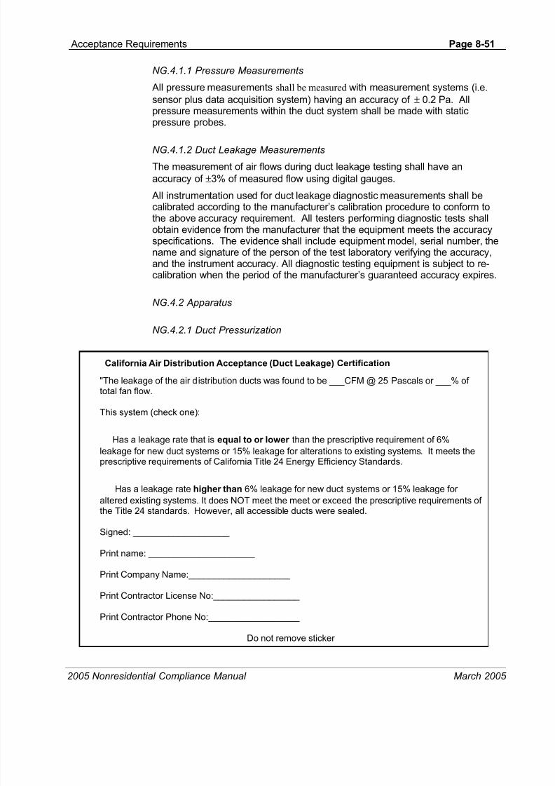
8/13/2019 FAT HVAC, Acceptance Requirements
http://slidepdf.com/reader/full/fat-hvac-acceptance-requirements 51/120
Acceptance Requirements Page 8-51
2005 Nonresidential Compliance Manual March 2005
NG.4.1.1 Pressure Measurements
All pressure measurements shall be measured with measurement systems (i.e.
sensor plus data acquisition system) having an accuracy of ± 0.2 Pa. Allpressure measurements within the duct system shall be made with staticpressure probes.
NG.4.1.2 Duct Leakage Measurements
The measurement of air flows during duct leakage testing shall have an
accuracy of ±3% of measured flow using digital gauges.
All instrumentation used for duct leakage diagnostic measurements shall becalibrated according to the manufacturer’s calibration procedure to conform tothe above accuracy requirement. All testers performing diagnostic tests shallobtain evidence from the manufacturer that the equipment meets the accuracyspecifications. The evidence shall include equipment model, serial number, thename and signature of the person of the test laboratory verifying the accuracy,and the instrument accuracy. All diagnostic testing equipment is subject to re-
calibration when the period of the manufacturer’s guaranteed accuracy expires.
NG.4.2 Apparatus
NG.4.2.1 Duct Pressurization
California Air Distribution Acceptance (Duct Leakage) Certification
"The leakage of the air distribution ducts was found to be ___CFM @ 25 Pascals or ___% oftotal fan flow.
This system (check one):
Has a leakage rate that is equal to or lower than the prescriptive requirement of 6%
leakage for new duct systems or 15% leakage for alterations to existing systems. It meets theprescriptive requirements of California Title 24 Energy Efficiency Standards.
Has a leakage rate higher than 6% leakage for new duct systems or 15% leakage for
altered existing systems. It does NOT meet the meet or exceed the prescriptive requirements ofthe Title 24 standards. However, all accessible ducts were sealed.
Signed: ___________________
Print name: _____________________
Print Company Name:____________________
Print Contractor License No:_________________
Print Contractor Phone No:__________________
Do not remove sticker
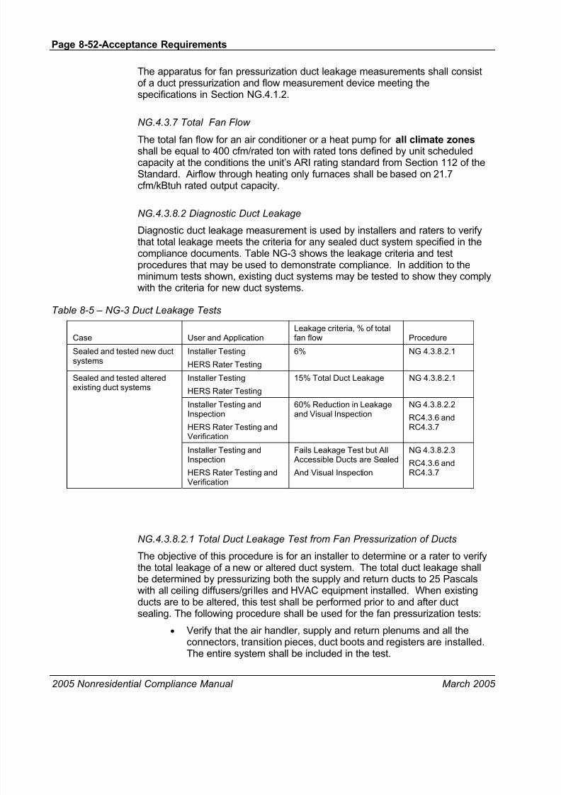
8/13/2019 FAT HVAC, Acceptance Requirements
http://slidepdf.com/reader/full/fat-hvac-acceptance-requirements 52/120
Page 8-52-Acceptance Requirements
2005 Nonresidential Compliance Manual March 2005
The apparatus for fan pressurization duct leakage measurements shall consistof a duct pressurization and flow measurement device meeting thespecifications in Section NG.4.1.2.
NG.4.3.7 Total Fan Flow
The total fan flow for an air conditioner or a heat pump for all climate zonesshall be equal to 400 cfm/rated ton with rated tons defined by unit scheduledcapacity at the conditions the unit’s ARI rating standard from Section 112 of theStandard. Airflow through heating only furnaces shall be based on 21.7cfm/kBtuh rated output capacity.
NG.4.3.8.2 Diagnostic Duct Leakage
Diagnostic duct leakage measurement is used by installers and raters to verifythat total leakage meets the criteria for any sealed duct system specified in thecompliance documents. Table NG-3 shows the leakage criteria and testprocedures that may be used to demonstrate compliance. In addition to the
minimum tests shown, existing duct systems may be tested to show they complywith the criteria for new duct systems.
Table 8-5 – NG-3 Duct Leakage Tests
Case User and ApplicationLeakage criteria, % of totalfan flow Procedure
Sealed and tested new ductsystems
Installer Testing
HERS Rater Testing
6% NG 4.3.8.2.1
Sealed and tested alteredexisting duct systems
Installer Testing
HERS Rater Testing
15% Total Duct Leakage NG 4.3.8.2.1
Installer Testing and
InspectionHERS Rater Testing andVerification
60% Reduction in Leakage
and Visual Inspection
NG 4.3.8.2.2
RC4.3.6 andRC4.3.7
Installer Testing andInspection
HERS Rater Testing andVerification
Fails Leakage Test but All Accessible Ducts are Sealed
And Visual Inspection
NG 4.3.8.2.3
RC4.3.6 andRC4.3.7
NG.4.3.8.2.1 Total Duct Leakage Test from Fan Pressurization of Ducts
The objective of this procedure is for an installer to determine or a rater to verifythe total leakage of a new or altered duct system. The total duct leakage shallbe determined by pressurizing both the supply and return ducts to 25 Pascalswith all ceiling diffusers/grilles and HVAC equipment installed. When existingducts are to be altered, this test shall be performed prior to and after ductsealing. The following procedure shall be used for the fan pressurization tests:
• Verify that the air handler, supply and return plenums and all theconnectors, transition pieces, duct boots and registers are installed.The entire system shall be included in the test.
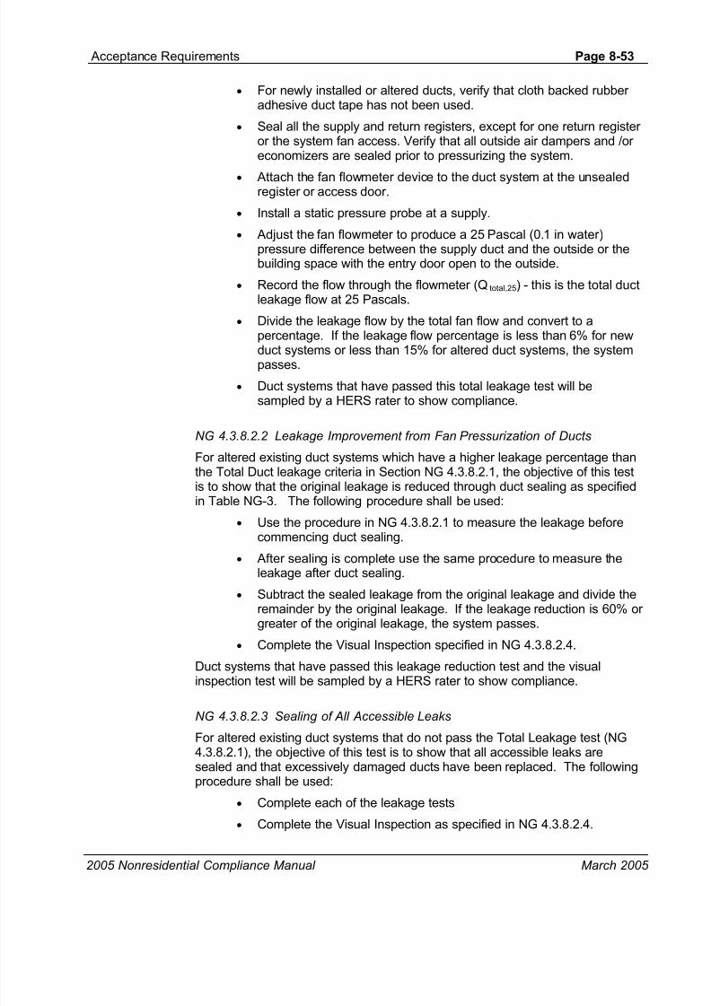
8/13/2019 FAT HVAC, Acceptance Requirements
http://slidepdf.com/reader/full/fat-hvac-acceptance-requirements 53/120
Acceptance Requirements Page 8-53
2005 Nonresidential Compliance Manual March 2005
• For newly installed or altered ducts, verify that cloth backed rubberadhesive duct tape has not been used.
• Seal all the supply and return registers, except for one return registeror the system fan access. Verify that all outside air dampers and /oreconomizers are sealed prior to pressurizing the system.
• Attach the fan flowmeter device to the duct system at the unsealedregister or access door.
• Install a static pressure probe at a supply.
• Adjust the fan flowmeter to produce a 25 Pascal (0.1 in water)pressure difference between the supply duct and the outside or thebuilding space with the entry door open to the outside.
• Record the flow through the flowmeter (Qtotal,25) - this is the total ductleakage flow at 25 Pascals.
• Divide the leakage flow by the total fan flow and convert to apercentage. If the leakage flow percentage is less than 6% for new
duct systems or less than 15% for altered duct systems, the systempasses.
• Duct systems that have passed this total leakage test will besampled by a HERS rater to show compliance.
NG 4.3.8.2.2 Leakage Improvement from Fan Pressurization of Ducts
For altered existing duct systems which have a higher leakage percentage thanthe Total Duct leakage criteria in Section NG 4.3.8.2.1, the objective of this testis to show that the original leakage is reduced through duct sealing as specifiedin Table NG-3. The following procedure shall be used:
•
Use the procedure in NG 4.3.8.2.1 to measure the leakage beforecommencing duct sealing.
• After sealing is complete use the same procedure to measure theleakage after duct sealing.
• Subtract the sealed leakage from the original leakage and divide theremainder by the original leakage. If the leakage reduction is 60% orgreater of the original leakage, the system passes.
• Complete the Visual Inspection specified in NG 4.3.8.2.4.
Duct systems that have passed this leakage reduction test and the visualinspection test will be sampled by a HERS rater to show compliance.
NG 4.3.8.2.3 Sealing of All Accessible Leaks
For altered existing duct systems that do not pass the Total Leakage test (NG4.3.8.2.1), the objective of this test is to show that all accessible leaks aresealed and that excessively damaged ducts have been replaced. The followingprocedure shall be used:
• Complete each of the leakage tests
• Complete the Visual Inspection as specified in NG 4.3.8.2.4.
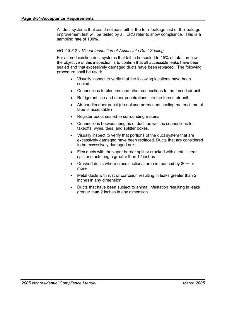
8/13/2019 FAT HVAC, Acceptance Requirements
http://slidepdf.com/reader/full/fat-hvac-acceptance-requirements 54/120
Page 8-54-Acceptance Requirements
2005 Nonresidential Compliance Manual March 2005
All duct systems that could not pass either the total leakage test or the leakageimprovement test will be tested by a HERS rater to show compliance. This is asampling rate of 100%.
NG 4.3.8.2.4 Visual Inspection of Accessible Duct Sealing
For altered existing duct systems that fail to be sealed to 15% of total fan flow,the objective of this inspection is to confirm that all accessible leaks have beensealed and that excessively damaged ducts have been replaced. The followingprocedure shall be used:
• Visually inspect to verify that the following locations have beensealed:
• Connections to plenums and other connections to the forced air unit
• Refrigerant line and other penetrations into the forced air unit
• Air handler door panel (do not use permanent sealing material, metaltape is acceptable)
• Register boots sealed to surrounding material
• Connections between lengths of duct, as well as connections totakeoffs, wyes, tees, and splitter boxes.
• Visually inspect to verify that portions of the duct system that areexcessively damaged have been replaced. Ducts that are consideredto be excessively damaged are:
• Flex ducts with the vapor barrier split or cracked with a total linearsplit or crack length greater than 12 inches
• Crushed ducts where cross-sectional area is reduced by 30% ormore
• Metal ducts with rust or corrosion resulting in leaks greater than 2inches in any dimension
• Ducts that have been subject to animal infestation resulting in leaksgreater than 2 inches in any dimension

8/13/2019 FAT HVAC, Acceptance Requirements
http://slidepdf.com/reader/full/fat-hvac-acceptance-requirements 55/120
Acceptance Requirements Page 8-55
2005 Nonresidential Compliance Manual March 2005
NG 4.3.8.4 Labeling requirements for tested systems
A sticker shall be affixed to the exterior surface of the air handler access doorwith the following text in 14 point font:
California Air Distribution Acceptance (Duct Leakage) Certification
"The leakage of the air distribution ducts was found to be ___CFM @ 25 Pascals or ___% of totalfan flow.
This system (check one):
Has a leakage rate that is equal to or lower than the prescriptive requirement of 6% leakagefor new duct systems or 15% leakage for alterations to existing systems. It meets the prescriptiverequirements of California Title 24 Energy Efficiency Standards.
Has a leakage rate higher than 6% leakage for new duct systems or 15% leakage for alteredexisting systems. It does NOT meet the meet or exceed the prescriptive requirements of the Title24 standards. However, all accessible ducts were sealed.
Signed: ___________________
Print name: _____________________
Print Company Name:____________________
Print Contractor License No:_________________
Print Contractor Phone No:__________________
Do not remove sticker"

8/13/2019 FAT HVAC, Acceptance Requirements
http://slidepdf.com/reader/full/fat-hvac-acceptance-requirements 56/120
Page 8-56-Acceptance Requirements
2005 Nonresidential Compliance Manual March 2005
8.6.11 NJ.8.1 Demand Control Ventilation Acceptance
At-a-Glance
NJ.8.1 Demand Control Ventilation Acceptance
Use Form MECH-6-APurpose of the Test
The purpose of the test is to verify that systems required to employ demand control ventilation (refer to§121(c)3) can vary outside ventilation flow rates based on maintaining interior carbon dioxide (CO2)concentration setpoints. Demand control ventilation refers to an HVAC system’s ability to reduce outsideair ventilation flow below design values when the space served is at less than design occupancy. CO2 isa good indicator of occupancy load and is the basis used for modulating ventilation flow rates.
Benefits of the Test
The Standards state that all non-exempt HVAC systems can maintain a minimum ventilation flow rate noless than the value calculated per §121(c)4.E, as long as measured CO2 concentrations do notexceed specified levels. Lowering ventilation airflow based on actual load (as indicated by CO2 level)
reduces energy usage associated with heating, cooling, or dehumidification of the outside ventilationair delivered to the space.
Instrumentation
To perform the test, it may be necessary to vary and possibly measure (if calibration is necessary)ambient CO2 levels. The instrumentation needed to perform the task may include, but is not limitedto:
• Hand-held reference CO2 probe calibrated to +/-10 ppm
Test Conditions
Equipment installation is complete (including HVAC unit, duct work, sensors, and control system).
HVAC system must be ready for system operation, including completion of all start-up procedures per
manufacturer’s recommendations.Building automation system (BAS) programming (if applicable) for the air handler and demand control
ventilation strategy must be complete. To perform the test, it may be necessary to use BAS tooverride or temporarily modify the CO2 sensor reading.
Air-Side Economizer is disabled so that it will not interfere with outside air damper operation during test.
Document the initial conditions before overrides or manipulation of the settings. All systems must bereturned to normal at the end of the test.

8/13/2019 FAT HVAC, Acceptance Requirements
http://slidepdf.com/reader/full/fat-hvac-acceptance-requirements 57/120
Acceptance Requirements Page 8-57
2005 Nonresidential Compliance Manual March 2005
Time to Complete
Construction inspection: 0.5 to 1 hours (depending on CO2 sensor calibration)
Equipment testing: 1 to 2 hours (depending on how ambient CO2 concentration levels are manipulated,system response time to variations in CO2)
Acceptance Criteria
Each CO2 sensor is factory calibrated (with calibration certificate) or field calibrated.
Each CO2 sensor is wired correctly to the controls to ensure proper control of the outdoor air damper.
Each CO2 sensor is located correctly within the space 1 to 6 feet above the floor.
Interior CO2 concentration setpoint is 600 ppm plus outside air CO2 value if dynamically measured or1000 ppm if no OSA sensor is provided.
A minimum OSA setting is provided whenever the system is in Occupied mode per Standard §121(c)4Eregardless of space CO2 readings.
A maximum OSA damper position for DCV control can be established per the exception to §121(c)4C,
regardless of space CO2 readings.The outside air damper modulates open when the CO2 concentration within the space exceeds setpoint,
The outside air damper modulates closed (toward minimum position) when the CO2 concentration withinthe space is below setpoint.
Potential Issues and Cautions
Lock out the economizer control during the test. Outside air damper may not modulate correctly if theeconomizer control strategy is controlling damper operation.
Overall test time may be reduced (especially for rooftop HVAC units) if two people perform the test - oneto vary the CO2 concentration while someone else verifies operation of the outside air dampers.
During the testing of the DCV controls, the outside damper will modulate open.. Care should be taken toprevent freezing of coils when testing with cold temperatures outside.
8.6.12 Test Procedure: NJ.8.1 Demand Control Ventilation Acceptance, Use
Form MECH-6-A
Test Comments and Applicability
The Standards require that only HVAC systems with the following characteristicsmust employ demand control ventilation:
• Single-zone systems. The intent was to limit the demand controlventilation requirement to systems that primarily serve spaces with
variable occupancy. Keep in mind, however, that it is possible that afacility may have a majority of spaces with fixed occupancy and onlya few variable occupancy zones that meet the requirement, but stillmust implement demand control ventilation for those variableoccupancy zones. Single-zone HVAC systems can include, but arenot limited to: 1) constant volume packaged units with stand-aloneeconomizer controllers (e.g., Honeywell W7340 Logic Module); or 2)constant volume systems with individual dampers/actuators andeither stand-alone or centralized DDC control.

8/13/2019 FAT HVAC, Acceptance Requirements
http://slidepdf.com/reader/full/fat-hvac-acceptance-requirements 58/120
Page 8-58-Acceptance Requirements
2005 Nonresidential Compliance Manual March 2005
• The HVAC system must have an economizer. The reason for thisrequirement is that the system must have the ability to modulateoutside airflow.
• Spaces served with specific use types or have the followingoccupancy densities, as described in the Uniform Building Code
(UBC) Chapter 10, must utilize DCV control:• Assembly areas, concentrated use (without fixed
seating); or
• Auction rooms; or
• Assembly areas, less concentrated use; or
• Occupancy density of 40 square feet per person orless. Occupancy density is calculated using UBCSection 1003.2.2.2.2 for spaces without fixed seatingand UBC Section 1003.2.2.2.3 for spaces with fixedseating. However, classrooms are exempt from thedemand control ventilation requirement.
The Standards state that the system will maintain a minimum ventilation flowrate no less than the value calculated per §121(c)4.E. This doesn’t necessarilyrequire that the system deliver less than design minimum, but it can if§121(c)4.E. is satisfied.
Construction Inspection
• The CO2 sensor is located within the control zone(s) between 1 ftand 6 ft above the floor. This is the critical range for measuring CO2 since most occupants will be typically either sitting or standing withinthe space.
• CO2 sensor is either factory calibrated or field calibrated. Acalibration certificate from the manufacturer will satisfy this
requirement. In order to perform a field calibration check, follow thecalibration procedures provided by the manufacturer. Some sensormanufacturers may require using equipment-specific calibration kits(kits may include trace gas samples and other hand-held devices)whereas others may be calibrated simply by using a pre-calibratedhand-held CO2 measuring device and making proper adjustmentsthrough the sensor or ventilation controller.
• Sensor is wired correctly to the controls to ensure proper control ofthe outdoor air damper. For stand-alone economizercontroller/actuators, this means that the CO2 sensor lead wires are
landed on the proper terminals and sensor polarity is correct. ForDDC controlled systems, ensure CO2 sensor value is being read –this will ensure that the sensor is connected to the DDC control panelcorrectly.
• Interior CO2 concentration setpoint is 600 ppm plus outside air CO2 value if outside concentration is measured dynamically. Else setpointis 1000 ppm. Outside air CO2 concentration can be determined bythree methods: 1) assume a value of 400 ppm without any directmeasurement; 2) measure outside concentration dynamically to
8/13/2019 FAT HVAC, Acceptance Requirements
http://slidepdf.com/reader/full/fat-hvac-acceptance-requirements 59/120
Acceptance Requirements Page 8-59
2005 Nonresidential Compliance Manual March 2005
continually adjust interior concentration setpoint; or 3) measureoutside concentration one time during system checkout and use thisvalue continually to determine inside concentration setpoint.
Equipment Testing
Step 1: Defeat the economizer.
Defeating the economizer will prevent the outside air damper from modulatingduring the test due to atmospheric conditions rather than CO2 variations. Theeconomizer can be defeated in a number of ways depending on the controlstrategy used to modulate the outside air dampers, however the simplestmethod would be to change the economizer changeover setpoint below currentatmospheric conditions. The changeover setpoint is the value that will lock outthe economizer, example control strategies include:
• Outside air dry-bulb temperature or enthalpy.
• Comparison between outside and return air temperature or enthalpy.
Step 2: Simulate a high CO 2 load.
The intent of this test is to ensure the outside air damper modulates open whenthe CO2 concentration within the space exceeds setpoint. Simulating a highCO2 load can be accomplished by, but not limited to: 1) commanding thesetpoint value to be slightly below current concentration level; 2) exposing thesensor to a known concentration of source gas (i.e. canister of CO2 gas with aconcentration greater than setpoint); or 3) exposing the sensor to an unknownconcentration (i.e. breathing excessively onto the sensor – human breath willprovide a very high concentration of CO2). Regardless of the method used tosimulate a high CO2 load, ensure the condition persists long enough for theHVAC system to respond.
Verify and Document
Ensure the outside air damper modulates open. If the CO2 setpoint is lowered just below current concentration levels, the outside air damper will modulateopen and the increased outside air should bring interior concentrations down tomeet and maintain the new setpoint. If a known concentration of CO2 gas wasused to simulate an elevated concentration, then the outside air damper maymodulate fully open since the “measured” concentration will not be influenced bythe increase in outside air (Note that §121(c)4.C states that outdoor ventilationrate is not required to exceed design minimum value calculated in §121(b)2,regardless of CO2 concentration. Therefore, the outside air damper may onlyopen to a position that provides the design minimum flow rate). If an unknownconcentration was used to simulate a high load, then the outside air dampercould modulate open and closed since the “measured” concentration may varyconsiderably throughout the test.
Step 3: Simulate a low CO 2 load.
The intent of this test is to ensure the outside air damper modulates towardsminimum position when the CO2 concentration within the space is belowsetpoint. Eventually the outside air damper should close to a position that

8/13/2019 FAT HVAC, Acceptance Requirements
http://slidepdf.com/reader/full/fat-hvac-acceptance-requirements 60/120
Page 8-60-Acceptance Requirements
2005 Nonresidential Compliance Manual March 2005
provides minimum ventilation flow rate per §121(c)4.E, regardless of how far themeasured interior concentration is below setpoint. Simulating a low CO2 loadcan be accomplished by, but not limited to: 1) commanding the setpoint value tobe slightly higher than current concentration level; 2) exposing the sensor to aknown concentration of source gas (i.e. canister of CO2 gas with a concentrationless than setpoint); or open doors and windows to reduce CO2 concentration in
the space.. Regardless of the method used to simulate a low CO2 load, ensurethe condition persists long enough for the HVAC system to respond.
Verify and Document
Ensure the outside air damper modulates towards minimum position. If setpointis raised just above current concentration levels, the outside air damper willmodulate closed and the reduced outside air should bring interior concentrationsup to meet and maintain the new setpoint. If necessary, continue to adjust thesetpoint upward until the outside air damper closes to a minimum position. If aknown concentration of CO2 gas was used to simulate a lowered concentration,then the outside air damper will most likely modulate to minimum position since
the “measured” concentration will not be influenced by the decrease in outsideair.
Step 4: Return system back to normal operating condition.
Ensure all schedules, setpoints, operating conditions, and control parametersare placed back at their initial conditions.

8/13/2019 FAT HVAC, Acceptance Requirements
http://slidepdf.com/reader/full/fat-hvac-acceptance-requirements 61/120
Acceptance Requirements Page 8-61
2005 Nonresidential Compliance Manual March 2005
8.6.13 NJ.9.1 Supply Fan Variable Flow Controls Acceptance
At-a-Glance
NJ.9.1 Supply Fan Variable Flow Controls Acceptance
Use Form MECH-7-APurpose of the Test
The purpose of the test is to ensure that the supply fan in a variable air volume application modulates tomeet system airflow demand. In most applications, the individual variable air valve (VAV) boxes servingeach space will modulate the amount of air delivered to the space based on heating and coolingrequirements. As a result, the total supply airflow provided by the central air handling unit must also varyto maintain sufficient airflow through each VAV box. Airflow is typically controlled using a variablefrequency drive (VFD) to modulate supply fan speed and vary system airflow. The most commonstrategy for controlling the VFD is to measure and maintain static pressure within the duct.
Related acceptance tests for these systems include the following:
•
NJ.3.1 Variable Air Volume Systems Outdoor Air Acceptance
Benefits of the Test
Using a VFD to reduce supply fan airflow as system loads decrease, is more energy efficient thanmodulation flow through other methods (i.e. inlet guide vanes or outlet dampers).
Instrumentation
The instrumentation needed to perform the task may include, but is not limited to:
• Differential pressure gauge
If applicable, supply air temperature reset should be disabled during testing to prevent any unwantedinteraction.
All systems and components must be installed and ready for system operation, including:
• Duct work
• VAV boxes
• Static pressure sensor(s) (note multiple sensors with separate control loops are oftenused on large systems with multiple branches)
• Electrical power to air handling unit
• Air handling unit start-up procedures are complete, per manufacturer’srecommendations

8/13/2019 FAT HVAC, Acceptance Requirements
http://slidepdf.com/reader/full/fat-hvac-acceptance-requirements 62/120

8/13/2019 FAT HVAC, Acceptance Requirements
http://slidepdf.com/reader/full/fat-hvac-acceptance-requirements 63/120

8/13/2019 FAT HVAC, Acceptance Requirements
http://slidepdf.com/reader/full/fat-hvac-acceptance-requirements 64/120
Page 8-64-Acceptance Requirements
2005 Nonresidential Compliance Manual March 2005
Step 2: Drive all VAV boxes to the greater of the minimum airflow or 30% of total designairflow.
The intent is to verify proper supply fan operation when the system is at or nearminimum flow conditions. This typically occurs when all of the VAV boxes areoperating at minimum cooling flow rate. There are a variety of ways to force the
VAV boxes to a minimum position depending on the building automation systemcapabilities and control strategies used, for example:
• Command all VAV boxes to minimum flow position (may beaccomplished by a global command or it may have to be done perindividual box).
• Set maximum flow setpoint to be the same as minimum flow setpoint(may be accomplished by a global command or it may have to bedone per individual box).
• Space temperature setpoint can be raised above current spaceconditions to force the VAV box into minimum cooling or heatingmode (may be accomplished by a global command or it may have to
be done per individual box or per zone thermostat). Again, you cannot simply override the VFD as it would negate the purpose ofthe test.
Verify and Document
• VFD reduces supply fan speed to meet flow conditions.
• Supply fan maintains discharge static pressure setpoint within ±10%.Verification can be accomplished by simply reading the value
measured by calibrated pressure sensor and comparing it tosetpoint.
• System operation stabilizes within 15 minutes. The intent is toensure the PID control loops are tuned properly so that the systemdoes not hunt.
Step 3: Return system back to normal operating condition. Ensure allschedules, setpoints, operating conditions, and control parameters are placedback at their initial conditions.

8/13/2019 FAT HVAC, Acceptance Requirements
http://slidepdf.com/reader/full/fat-hvac-acceptance-requirements 65/120
Acceptance Requirements Page 8-65
2005 Nonresidential Compliance Manual March 2005
8.6.15 NJ.10.1 Variable Hydronic Flow Controls Acceptance
At-a-Glance
NJ.10.1 Variable (Hydronic) Flow Controls Acceptance
Use Form MECH-8-APurpose of the Test
The purpose of this test is to ensure that all chilled or heating water configurations with more than 3control valves are designed and operated so that total system flow changes as load requirementsfluctuate, i.e., the design incorporates two-way control valves at some if not all of the coils. A cooling andheating load is typically met by modulating the amount of water that flows through the respective coilusing a control valve. The Standards require that total system flow rate vary as a function of load; that is,the flow rate should decrease when the system calls for less-than-design flow.
Related acceptance tests for these systems include the following:
• NJ.10.2 Automatic Isolation Controls Acceptance
• NJ.10.5 (Pump)Variable Frequency Drive Controls Acceptance
• Testing time will be greatly reduced if these acceptance tests are donesimultaneously.
NOTE: There are two alternative tests applicable to this measure depending on system design: Alternate1 – with flow measurement and Alternate 2 – without flow measurement. The Acceptance Agent mayselect either of these two tests to comply.
Benefits of the Test
Modulating the system flow rate to meet load – rather than maintaining a constant flow throughout theentire system – helps to reduce pumping energy and improve heating and cooling plant efficiencies.
Instrumentation
Performance of this test will require measuring total hydronic system flow rate. The instrumentationneeded to perform the task may include, but is not limited to:
• Differential pressure gauge
Test Conditions
The whole hydronic system must be complete – all coils, control valves, and pumps installed; all piping ispressure tested, flushed, cleaned, filled with water; BAS controls, if applicable.
All equipment start-up procedures are complete, per manufacturer’s recommendations.
Document the initial conditions before overrides or manipulation of the BAS. All systems must bereturned to normal at the end of the test.

8/13/2019 FAT HVAC, Acceptance Requirements
http://slidepdf.com/reader/full/fat-hvac-acceptance-requirements 66/120
8/13/2019 FAT HVAC, Acceptance Requirements
http://slidepdf.com/reader/full/fat-hvac-acceptance-requirements 67/120

8/13/2019 FAT HVAC, Acceptance Requirements
http://slidepdf.com/reader/full/fat-hvac-acceptance-requirements 68/120
Page 8-68-Acceptance Requirements
2005 Nonresidential Compliance Manual March 2005
(for example there may be three-way valves located at one or moreof the coils to ensure system minimum flow rates can be achieved).
Equipment Testing
Step 1: Deadhead One Pump. The intent of this test is to establish a baseline
pump pressure for use in checking the ability of all valves to close across thesystem. Use manual isolation or balance valves at the inlet or bypass of allthree way valves and close it off. If a balance valve is used mark its currentposition so that it can be reset after the test.
Isolate one circulation pump and make sure that all chillers or boilers are off.Close off the isolation valve at the pumps discharge and turn the pump on fornot more than 5 minutes. Measure and note the pressure across the pump atthis “deadhead” condition. If the system is piped primary/secondary make surethis is a secondary pump. At the end of the measurement turn off the pump andopen the discharge valve at the pump.
Verify and Document
Step 2: Close control valves. The intent of this test is to ensure that all two-way valves can modulate fully closed and have actuators that can fully closeacross an operating pump. With the chillers or boiler still off, start the samepump that was used in Step 1 and drive all HX or coil control valves closed.Closing the control valves can be achieved in a variety of ways, examples ofwhich include: resetting control setpoints so that valves respond accordingly;commanding the valves directly using the DDC control system (i.e., buildingautomation system); or applying a fixed amount of air pressure to an actuator orvalve in the case of a pneumatic control system. Make sure that the pumpoperates for no more than 5 minutes in this “deadhead” condition.
Verify and Document
• Ensure each control valve closes completely under normal operatingpressure. The intent is to make sure that the actuator-valve torquerequirements are adequate to shut the valve under normal operatingsystem pressure. Verifying complete closure shall be done bymeasuring the pressure across the operating pump. If the pressureis more than 5% less than that previously measured the test fails asone or more valves have not fully closed. Diagnose and fix theproblem then retest.
Step 3: Return system back to normal operating condition. Ensure allschedules, setpoints, isolation and balance valves, operating conditions, andcontrol parameters are placed back at their initial conditions.

8/13/2019 FAT HVAC, Acceptance Requirements
http://slidepdf.com/reader/full/fat-hvac-acceptance-requirements 69/120
Acceptance Requirements Page 8-69
2005 Nonresidential Compliance Manual March 2005
8.6.16 NJ.10.2 Automatic Isolation Controls Acceptance
At-a-Glance
NJ.10.2 Automatic Isolation Controls Acceptance
Use Form MECH-8-APurpose of the Test
Many HVAC systems are served by central chilled water and heating hot water plants that consist ofmultiple pieces of equipment that work cooperatively to meet total system load. Often, each piece ofequipment is sized so that only a particular unit will operate at a given time based on the performancecharacteristics of that unit and its ability to serve the load. For example, a 600-ton cooling load may beserved by two 300-ton chillers, with one unit operating when the load is less than 300 tons and bothoperating to satisfy higher loads.
The purpose of the test is to verify that each piece of equipment is automatically isolated from thecondenser, chilled or hot water flow when it is not in operation; that is, the isolation valves serving eachpiece of equipment open fully before the equipment is started and close fully once the equipment isturned off. Note for equipment with dedicated pumps and check valves, automatic isolation valves andthis test are not required.
Related acceptance tests for these systems include the following:
• NJ.10.1 Variable (Hydronic) Flow Controls Acceptance
Benefits of the Test
Ensuring that automatic equipment isolation controls are operating correctly will avert excess pumpenergy and control problems due to the bypass of unconditioned water.
Instrumentation
To perform the test, it will be necessary to verify correct operation of the isolation valves during start-upand shutdown and that the valves close completely. There is no instrumentation needed to perform thistask.
Test Conditions
Each piece of equipment, along with the respective isolation valve, must be installed and started up.
If using the BAS to enable “start” and “stop” commands for the equipment, then programming of thestart/stop sequences and control valves must be complete.
The whole hydronic system must be complete – all coils, control valves, and pumps installed; all piping ispressure tested, flushed, cleaned, filled with water; BAS controls, if applicable.
Document the initial conditions before overrides or manipulation of the BAS. All systems must bereturned to normal at the end of the test.
8/13/2019 FAT HVAC, Acceptance Requirements
http://slidepdf.com/reader/full/fat-hvac-acceptance-requirements 70/120
8/13/2019 FAT HVAC, Acceptance Requirements
http://slidepdf.com/reader/full/fat-hvac-acceptance-requirements 71/120
Acceptance Requirements Page 8-71
2005 Nonresidential Compliance Manual March 2005
Verify and Document
• As each chiller or boiler is started visually verify that the isolationvalve(s) open fully.
• Ensure each isolation valve closes completely under normaloperating pressure. The intent is to make sure that the actuator-
valve torque requirements are adequate to shut the valve undernormal operating system pressure. Verifying complete closure shallbe done by measuring the pressure across the operating pump. Ifthe pressure is more than 5% less than that previously measured,the test fails as one or more valves have not fully closed. Diagnoseand fix the problem, then retest.
Step 3: Return system back to normal operating condition. Ensure allschedules, setpoints, isolation and balance valves, operating conditions, andcontrol parameters are placed back at their initial conditions.
8.6.17 NJ.10.3 Supply Water Temperature Reset Controls Acceptance
At-a-Glance
NJ.10.3 Supply Water Temperature Reset Controls Acceptance
Use Form MECH-8-APurpose of the Test
The intent of the test is to ensure that both the chilled water and hot water supply temperatures areautomatically reset based on either building loads or outside air temperature, as indicated in the controlsequences. Many HVAC systems are served by central chilled and heating hot water plants. Thesupply water operating temperatures must meet peak loads when the system is operating at design
conditions. As the loads vary, the supply water temperatures can be adjusted to satisfy the newoperating conditions. Typically the chilled water supply temperature can be raised as the cooling loaddecreases, and heating hot water supply temperature can be lowered as the heating load decreases.
This requirement only applies to chilled and hot water systems that are not designed for variable flowand that have a design capacity greater than or equal to 500 MBh (thousand BTU’s per hour).

8/13/2019 FAT HVAC, Acceptance Requirements
http://slidepdf.com/reader/full/fat-hvac-acceptance-requirements 72/120

8/13/2019 FAT HVAC, Acceptance Requirements
http://slidepdf.com/reader/full/fat-hvac-acceptance-requirements 73/120
Acceptance Requirements Page 8-73
2005 Nonresidential Compliance Manual March 2005
Test Procedure: NJ.10.3 Supply Water Temperature Reset Controls Acceptance, UseForm MECH-8-A
Test Comments
The most common control variables used to reset supply water temperature
setpoint include, but are not limited to: coil valve position; outside airtemperature; and space conditioning parameters like humidity. Examples ofeach control strategy are provided below.
• Coil valve position. A central energy management system is used tomonitor cooling coil and/or heating coil valve positions to determinewhen the supply water temperature can be reset. The followingexample highlights a common heating hot water control strategy, inwhich all heating coil valve positions (central heating and re-heatcoils) are monitored to determine current valve position. If all heatingvalves are less than 94% open, then the hot water supplytemperature will be incrementally lowered until one valve opens to94% and then the setpoint is maintained. If any valve opens to morethan 98% open, then the hot water supply temperature will beincrementally raised and maintained until one valve drops back downto 94% open. A similar control strategy can be used to reset thechilled water supply temperature. The chilled and hot watertemperature setpoint values will be determined by the designer andshould be available from either the design narrative, specifications,or control drawings.
• Outside air temperature. Another very common control strategy is toreset supply water temperature based on outside air temperature.Depending on the building type, internal loads, and designconditions, the designer may develop a relationship between the
chilled and hot water supply temperatures necessary to satisfybuilding loads at various outside air temperatures. For example, hotwater temperature may be reset linearly between 90°F and 140°Fwhen outside air temperature is above 50°F and below 35°F,respectively. Actual supply water and outside air temperatures willbe determined by the designer and should be available from eitherthe design narrative, specifications, or control drawings.
• Humidity control. For special applications like hospitals, museums,semiconductor fabrication and laboratories, the cooling coil controlmay be based on maintaining a constant relative humidity within thespace for not only comfort but also indoor air quality and moisturecontrol (i.e. mold issues). Therefore, the temperature of the chilled
water delivered to the coil should be sufficient to remove moisturefrom the supply air stream and the chilled water temperature can bereset upwards as the latent load decreases. Actual chilled watertemperature setpoint reset schedule will be determined by thedesigner and should be available from either the design narrative,specifications, or control drawings.

8/13/2019 FAT HVAC, Acceptance Requirements
http://slidepdf.com/reader/full/fat-hvac-acceptance-requirements 74/120
Page 8-74-Acceptance Requirements
2005 Nonresidential Compliance Manual March 2005
Construction Inspection
• Temperature sensors are either factory calibrated or field calibrated.Depending on the control strategy used to reset supply watertemperature, sensors can include, but are not limited to: 1) supplywater temperature sensor; and outside air temperature sensor (if
used for reset). Calibration certificates from the manufacturer areacceptable. Field calibration requires using either a secondarytemperature reference or placing the sensor in a known temperatureenvironment (typically either ice water or a calibrated dry-well bath).When field calibrating temperature sensors, it is recommended thatyou perform a “through system” calibration that compares thereference reading to the reading at the EMCS front end or inside thecontroller (e.g. it includes any signal degradation due to wiring andtransducer error).
• Sensor locations are adequate to achieve accurate measurements.Water temperature sensors will typically be located in immersionwells on the supply side of each piece of equipment, and the
equipment will be controlled accordingly to meet supply temperaturesetpoint. Location of the outside air temperature sensor is muchmore critical. The sensor should not be exposed to direct sun(preferably mounted on a north-facing wall with a protective cover) orany other heat sources like exhaust streams, cooling towers, orgeneration equipment.
• Sensors comply with specifications. Proper control depends on theinstallation of good sensors. Review all sensor cut sheets and verifyinstalled sensors meet all performance requirements as detailed inthe specifications.
Equipment Testing
Step 1. Achieve maximum supply water temperature setpoint (coldest forchilled water and warmest for heating water). Manually change the controlvariable in order to reset supply water temperature. For a valve position controlstrategy, command at least one coil valve to 100% open. An alternate methodwould be to adjust discharge air temperature or zone temperature setpoints todrive a valve into a 100% open condition. For an outside air temperature controlstrategy, override actual outside air sensor to exceed maximum water
temperature boundary value. For example, if the control strategy calls for 42°F
chilled water when outside air temperature is above 70°F, command the sensor
to read 72°F. For a humidity control sequence, command the humidity setpointto be 5% below actual humidity conditions.
Verify and Document
• Chilled and/or heating hot water supply temperature setpoint is resetto the appropriate value determined by the designer per the controlstrategy.
• Actual supply water temperature changes to meet the new setpoint.It may take a few minutes for the water temperature to changedepending on system conditions and equipment operation.

8/13/2019 FAT HVAC, Acceptance Requirements
http://slidepdf.com/reader/full/fat-hvac-acceptance-requirements 75/120
Acceptance Requirements Page 8-75
2005 Nonresidential Compliance Manual March 2005
Step 2. Achieve minimum supply water temperature setpoint (warmest forchilled water and coldest for heating water). Manually change the controlvariable in order to reset supply water temperature. For a valve position controlstrategy, command all coil valves to only be partially open. Continuing with oneof the examples above, if supply water temperature is reset when a valve is lessthan 94% open, command all valves to be 90% open. An alternate method
would be to adjust discharge air temperature or zone temperature setpoints todrive a valve into a partially open condition. For an outside air temperaturecontrol strategy, override actual outside air sensor to exceed minimum water
temperature boundary value. For example, if the control strategy calls for 90°F
heating water when outside air temperature is above 50°F, command the sensor
to read 52°F.
Verify and Document
• Chilled and/or heating hot water supply temperature setpoint is resetto the appropriate value determined by the designer per the controlstrategy.
• Actual supply water temperature changes to meet the new setpoint.It may take a few minutes for the water temperature to changedepending on system conditions and equipment operation.
Step 3: Return system back to normal operating condition. Ensure allschedules, setpoints, operating conditions, and control parameters are placedback at their initial conditions.

8/13/2019 FAT HVAC, Acceptance Requirements
http://slidepdf.com/reader/full/fat-hvac-acceptance-requirements 76/120
Page 8-76-Acceptance Requirements
2005 Nonresidential Compliance Manual March 2005
8.6.18 NJ.10.4 Water-loop Heat Pump Controls Acceptance
At-a-Glance
NJ.10.4 Water-loop Heat Pump Controls Acceptance
Use Form MECH-8-APurpose of the Test
For water-loop heat pump systems with total loop pump capacity greater than 5 hp, two-way isolationvalves are required at each heat pump. These valves close when the heat pump’s compressor hascycled off. This causes the flow through the loop to vary which saves energy. In addition, eachindividual loop pump with a motor greater than 5 hp is required to have a VSD to control it’s capacity(smaller pumps may ride the pump curve).
Related acceptance tests for these systems include the following:
NJ.10.5 (Pump) Variable Frequency Drive Controls Acceptance
• Note that this test should be performed in conjunction with NJ.10.5 (Pump) VariableFrequency Drive Controls Acceptance test if a VFD is required.
• NOTE: There are two alternative tests for this measure: Alternate 1 – with flowmeasurement and Alternate 2 – without flow measurement. The Acceptance Agentmay select either of the two tests to perform.
Benefits of the Test
By adjusting the overall system flow rate to match operating load, pumping energy can be reduced atpart-load operating condition.
Instrumentation
Performance of this test will require measuring total hydronic system flow rate and pump power. Theinstrumentation needed to perform the task may include, but is not limited to:
• Differential pressure gauge

8/13/2019 FAT HVAC, Acceptance Requirements
http://slidepdf.com/reader/full/fat-hvac-acceptance-requirements 77/120
Acceptance Requirements Page 8-77
2005 Nonresidential Compliance Manual March 2005
Test Conditions
To perform the test, the control system will be used to manipulate system operation to achieve thedesired control. At a minimum, the control system for the operation of the heat pumps, controlvalves, and water pumps must be complete, including:
• Equipment start-stop control
• Thermostatic control of zones
• Interlock control of isolation valves
• Circulation pump controls including start-stop and flow controls
All systems must be installed and ready for system operation, including:
• Heat pumps, cooling towers, boilers, pumps, control valves, piping, etc.
• All piping is pressure tested, flushed, cleaned, and filled with water
• Control sensors (temperature, flow, pressure, etc.)
• Electrical power to all equipment
• Start-up procedures for all pieces of equipment are complete, per manufacturer’srecommendations
Document the initial conditions before overrides or manipulation of the control system. All systems mustbe returned to normal at the end of the test.
Time to Complete
Construction inspection: 1 to 2 hours (depending on the number of heat pumps and the quality of thedocumentation.)
Equipment testing: 2 to 4 hours (depending on familiarity with BAS, method employed to varyoperating parameters, verification method for tight valve closure, VFD test if applicable)
Acceptance Criteria
All equipment installed per drawings (two-way control valves, sensors)
Potential Issues and Cautions
Difficulties could be encountered with manipulating the control system if not familiar with theprogramming language. Therefore, a controls contractor should be on-site to assist withcommanding the heat pumps and adjusting system operation.
Test Procedure: NJ.10.4 Water-loop Heat Pump Controls Acceptance, Use Form MECH- 8-A, (Alternate 1 – with flow measurement)
Test Comments
A typical water-loop heat pump system may consist of the following equipment:1) water-source heat pumps; 2) one or more circulation pumps (possibly withVFDs); 3) cooling tower (used to dissipate excess heat from the loop); and 4)hot water heating unit (used to add heat to the loop as necessary). A commonstrategy for controlling the circulation pump VFD would be to maintain aconstant system pressure, or differential pressure between supply and return,within the water circuit with the greatest pressure drop (typically the most remote
8/13/2019 FAT HVAC, Acceptance Requirements
http://slidepdf.com/reader/full/fat-hvac-acceptance-requirements 78/120
Page 8-78-Acceptance Requirements
2005 Nonresidential Compliance Manual March 2005
heat pump in the loop). This control strategy would require the installation of adifferential pressure sensor preferably far down the loop. The boilers andtowers may have a by-pass line and primary pumps to ensure minimum loopflow is maintained. If the water-loop circulating pump is controlled by a VFD, theVFD performance tests are executed in NJ10.5 (Pump) Variable FrequencyDrive Controls procedures.
Construction Inspection
• Ensure all valve and piping arrangements were installed per thedesign drawings in order to achieve the desired control. This refersto each heat pump having its own two-way control valve and ismounted in such a manner that process water cannot flow throughthe unit when it is not operating.
• Verify all valve and hydronic connection pressure ratings meetspecifications. Verification includes reviewing equipmentspecification cut sheets.
Equipment Testing
Step 1. Start all heat pumps. Command all heat pumps to be enabled, whichcan be accomplished by simply commanding each unit to operate or byadjusting space temperature setpoints to be outside the existing spacetemperature.
Verify and Document
• System operation achieves design conditions within ±5%. All of thetwo-way control valves should automatically open when thecorresponding heat pump is operating, and the system shouldoperate at or near design flow rate.
Step 2. Adjust system to test two-way control valves. Command severalheat pumps to be disabled, which can be accomplished by simply commandingeach unit OFF or by adjusting space temperature setpoints to be within theexisting space temperature.
Verify and Document
• For the units commanded OFF, the two-way control valves shouldautomatically close upon compressor shut down.
• Ensure each two-way control valve closes completely under normaloperating pressure. The intent is to make sure that the actuator-valve torque requirements are adequate to shut the valve under
normal operating system pressure. Complete closure can be verifiedif measured system flow has reduced by an amount equivalent to thecumulative flow of the disabled heat pumps.
Step 3: Return system back to normal operating condition. Ensure allschedules, setpoints, operating conditions, and control parameters are placedback at their initial conditions.

8/13/2019 FAT HVAC, Acceptance Requirements
http://slidepdf.com/reader/full/fat-hvac-acceptance-requirements 79/120
Acceptance Requirements Page 8-79
2005 Nonresidential Compliance Manual March 2005
Test Procedure: NJ.10.4 Water-loop Heat Pump Controls Acceptance, Use Form MECH- 8-A, (Alternate 2 – without flow measurement) Construction Inspection
• Ensure all valve and piping arrangements were installed per thedesign drawings in order to achieve the desired control. This refersto each heat pump having its own two-way control valve and is
mounted in such a manner that process water cannot flow throughthe unit when it is not operating.
Equipment Testing
Step 1: Deadhead One Loop Pump. The intent of this test is to establish abaseline pump pressure for use in checking the ability of all isolation valves toclose across the system.
Isolate one loop pump and make sure that all towers, boilers and heat pumpsare off. Close off the isolation valve at the pumps discharge and turn the pumpon for not more than 5 minutes. Measure and note the pressure across thepump at this “deadhead” condition. If the system is piped primary/secondary,make sure this is a secondary pump. At the end of the measurement turn offthe pump and open the discharge valve at the pump.
Verify and Document
• Note the “deadhead” pressure of the circulation pump. This will beused in the next test.
Step 2: Close all heat pump control valves. Temporarily disable all heatpumps so that their two-way isolation valves close. The intent of this test is toensure that all two-way valves can modulate fully closed and have actuators thatcan fully close across an operating pump. With the towers and boilers still off,start the same pump that was used in Step 1. Closing the heat pump isolationvalves can be achieved in a variety of ways, examples of which include:
resetting all thermostats to put them into the dead band (where no heating orcooling is called for); or commanding the heat pumps directly using the DDCcontrol system (i.e., building automation system). Make sure that the pumpoperates for no more than 5 minutes in this “deadhead” condition.
Verify and Document
• Ensure each control valve closes completely under normal operatingpressure. The intent is to make sure that the actuator-valve torquerequirements are adequate to shut the valve under normal operatingsystem pressure. Verifying complete closure shall be done bymeasuring the pressure across the operating pump. If the pressure
is more than 5% less than that previously measured the test fails asone or more valves have not fully closed. Diagnose and fix theproblem, then retest.
Step 3: Return system back to normal operating condition. Ensure allschedules, setpoints, isolation and balance valves, operating conditions, andcontrol parameters are placed back at their initial conditions.

8/13/2019 FAT HVAC, Acceptance Requirements
http://slidepdf.com/reader/full/fat-hvac-acceptance-requirements 80/120

8/13/2019 FAT HVAC, Acceptance Requirements
http://slidepdf.com/reader/full/fat-hvac-acceptance-requirements 81/120
Acceptance Requirements Page 8-81
2005 Nonresidential Compliance Manual March 2005
Test Conditions
To perform the test, it will be necessary to use the control system to manipulate system operation toachieve the desired control. At a minimum, control system programming for the operation of thecentral equipment, control valves, and pumps must be complete, including, but not limited to:
• Equipment start-stop control
• All control sensors installed and calibrated
• Control loops are tuned
All systems must be installed and ready for system operation, including:
• Heat pumps, cooling towers, boilers, pumps, control valves, piping, etc.
• All piping is pressure tested, flushed, cleaned, and filled with water
• Control sensors (temperature, flow, pressure, etc.)
• Electrical power to all equipment
• Start-up procedures for all pieces of equipment are complete, per manufacturer’s
recommendationsDocument the initial conditions before overrides or manipulation of the BAS. All systems must be
returned to normal at the end of the test.
Time to Complete
Construction inspection: 0.5 to 1 hour (depending on availability of construction documentation – i.e.plumbing drawings, material cut sheets, specifications, etc – as well as sensor calibration)
Equipment testing: 2 to 4 hours (depending on familiarity with BAS, method employed to varyoperating parameters, verification method for system flow and VFD power)
Acceptance Criteria
Differential pressure sensor is either factory calibrated (with calibration certificates) or field calibrated.
Pressure sensor is located at or near the most remote HX or control valve.
System controls to the setpoint stably.
Potential Problems and Cautions
Difficulties could be encountered with manipulating the control system if not familiar with theprogramming language. Therefore, a controls contractor should be on-site to assist with adjustingsystem operation and overriding controls.
Test Procedure: NJ.10.5 (Pump) Variable Frequency Drive Controls Acceptance,
comments and construction inspection common to both Alternative 1 (without flowmeters) and Alternative 2 (with flow meters)
Test Comments
§144(j)6 permits two general VFD control strategies: one based on system flow;and the other based on differential system pressure. The most common controlstrategy employed to control the pump VFD is to maintain constant differentialpressure between supply and return within the water circuit with the greatest

8/13/2019 FAT HVAC, Acceptance Requirements
http://slidepdf.com/reader/full/fat-hvac-acceptance-requirements 82/120
Page 8-82-Acceptance Requirements
2005 Nonresidential Compliance Manual March 2005
pressure drop (typically the most remote heat exchanger or coil in the loop). Aflow-based control strategy would require either the calculation or directmeasurement of system flow in order to control the pump speed effectively.Regardless of the control strategy employed, the intent of the test is to ensurethat as each control valve modulates, the pump VFD responds accordingly tomeet system water flow requirements.
• It is recommended that minimum VFD speed setpoint be verified. Ifthe minimum speed is too low, equipment may not operate correctly.However, if the minimum speed is too high, the system will not beallowed to turn down and the full energy savings of the VFD will notbe achieved. Guidance for setting minimum speed setpoint isprovided below:
1. The VFD minimum speed setpoint should meet the equipmentmanufacturer’s requirements, including pump motors, hot water heating unit,and cooling tower. Typically most motor manufacturers do not recommendoperating for extended periods of time below a designated speed becauseheat build-up in the motor can adversely effect winding insulation and motor
efficiency. Chillers and heating hot water units may also require a specificflow rate through the unit to ensure proper operation. For example, in aprimary-only chilled water system, the chiller manufacturer will dictate theminimum flow rate of chilled water through the evaporator.
2. VFD minimum setpoint should not be below the point where energy useincreases. Both the drive and motor efficiencies decrease at reduced loadand eventually a point is reached where a continued reduction in load (i.e.,speed) results in an increase in energy usage. Depending on the systemcharacteristics and equipment served, other factors may dictate minimumVFD speed (i.e., equipment manufacturer’s requirements), but the minimumspeed maintained by the VFD should never be set below this power inflectionpoint. Many VFDs can measure and display power usage on its control
screen and it is a simple process of reducing system speed and watchingpower consumption to determine the inflection point. If the VFD cannotmeasure power, measuring motor amperage would be a good substitute –inflection point is reached when motor amperage starts to increase.
Construction Inspection
• Sensor location is adequate to achieve the desired control. Systempressure or differential pressure sensor must be located near themost distant heat exchanger or coil. Verify actual sensor locationmatches design drawings.
• The differential pressure sensor (if applicable) is either factorycalibrated or field calibrated. Calibration certificates from themanufacturer are acceptable. Field calibration would requiremeasuring system pressure, or differential pressure, as close to theexisting sensor as possible using a calibrated hand-held measuringdevice and comparing the field measured value to the valuemeasured by the BAS.
8/13/2019 FAT HVAC, Acceptance Requirements
http://slidepdf.com/reader/full/fat-hvac-acceptance-requirements 83/120
Acceptance Requirements Page 8-83
2005 Nonresidential Compliance Manual March 2005
Test Procedure: NJ.10.5 (Pump) Variable Frequency Drive Controls Acceptance, UseForm MECH-8-A, (Alternate 1 – for systems without flow meters)
It is acceptable to use this method to verify VFD operation even if the controldoes have a flow meter. This method compares VFD speed and pressure at fulland minimum flow. If at minimum flow, VFD speed is decreased and system
pressure is no greater than at full flow, the system is compliant.
Equipment Testing
Step 1. Open all control valves. Ensure all control valves are 100% open.Opening the control valves can be achieved in a variety of ways, such as:resetting control setpoints so that valves respond accordingly, commanding thevalves directly using the DDC control system (i.e., building automation system),or applying a fixed amount of air pressure to an actuator or valve in the case ofa pneumatic control system.
Verify and Document
• Make note of VFD output – it should be close to 100% speed• Record system pressure at loop pressure sensor control point
• System pressure should stabilize within 5 minutes.
Step 2. Modulate control valves closed. Closing control valves can beaccomplished by simply commanding each valve to a specific position or byadjusting temperature setpoints to be within the existing temperature range.
Verify and Document
• Spot check to ensure that valves are closed.
• As the control valves close, the VFD should reduce pump speed.
Reduction in pump speed should be commensurate with theexpected decrease in water flow.
• Record system pressure at loop pressure sensor control point
• System pressure can be no greater at minimum flow than at full flow.
• Ensure system operation stabilizes within 5 minutes after initiating avalve closure procedure. The intent is to verify that the VFD controlPID loop is tuned properly so that changes in system pressure(differential pressure-based control strategy), or flow (flow-basedcontrol strategy) due to valve position do not cause excessivehunting of the VFD to achieve proper system flow.
Step 3. Return system back to normal operating condition. Ensure allschedules, setpoints, operating conditions, and control parameters are placedback at their initial conditions.
Test Procedure: NJ.10.5 (Pump) Variable Frequency Drive Controls Acceptance, UseForm MECH-8-A, (Alternate 2 – for systems with flow meters)
This test assures that power draw of the VFD and pump at 50% flow is nogreater than 30% of power draw at full flow.

8/13/2019 FAT HVAC, Acceptance Requirements
http://slidepdf.com/reader/full/fat-hvac-acceptance-requirements 84/120
Page 8-84-Acceptance Requirements
2005 Nonresidential Compliance Manual March 2005
Equipment Testing
Step 1. Open all control valves. Ensure all control valves are 100% open.Opening the control valves can be achieved in a variety of ways, such as:resetting control setpoints so that valves respond accordingly, commanding thevalves directly using the DDC control system (i.e., building automation system),
or applying a fixed amount of air pressure to an actuator or valve in the case ofa pneumatic control system.
Verify and Document
• System operation achieves design conditions within ±5%. All of thetwo-way control valves should open fully and the system shouldoperate at or near design flow rate. Verifying system flow rate canbe accomplished by reading flow measured with installed flow meter.
Step 2. Modulate control valves closed. Closing control valves can beaccomplished by simply commanding each valve to a specific position or byadjusting temperature setpoints to be within the existing temperature range.
Verify and Document
• Ensure each two-way control valve closes completely under normaloperating pressure. The intent is to make sure that the actuator-valve torque requirements are adequate to close the valve undernormal operating system pressure. Complete closure can beverifying that the measured system flow has reduced by an amountequivalent to the cumulative flow of the closed coils.
• As the control valves close, the VFD should reduce pump speed.Reduction in pump speed should be commensurate with theexpected decrease in water flow.
• Ensure system operation stabilizes within 5 minutes after initiating avalve closure procedure. The intent is to verify that the VFD controlPID loop is tuned properly so that changes in system pressure(differential pressure-based control) or flow (flow-based controlstrategy) due to valve position do not cause excessive hunting of theVFD to achieve proper system flow.
Step 3. Adjust system operation to achieve 50% flow. The intent of this testis to verify pump input power meets the required reduction stipulated in §144(j)6at 50% design flow. Review all heat exchanger and coil flow rates and varyvalve position as necessary to achieve a 50% flow condition.
Verify and Document
• The input power consumption for the pump motor/VFD does notexceed 30% of full-load power at a 50% flow condition. Input powercan be verified by reading power (kW) directly from the drive if thesystem has the capability, or a power meter can be used. Otherwise,measure voltage and amperage at each leg of the VFD, assume areasonable part-load system power factor, and calculate powerbased on: 1.73*Voltave*Ampave*power factor. At 30% of full-load

8/13/2019 FAT HVAC, Acceptance Requirements
http://slidepdf.com/reader/full/fat-hvac-acceptance-requirements 85/120
Acceptance Requirements Page 8-85
2005 Nonresidential Compliance Manual March 2005
power, the power factor may range from 50%-70%. It is preferable toverify power factor using motor manufacturer performance data.
• Note: If there are any large imbalances (±10% or greater for voltage
and ±20% or greater for amperage) between each leg, this may beindicative of an electrical system problem which could impact system
operation and equipment life.Step 4. Adjust system operation to verify system minimum flow. Theremay be situations where the water flow rate required by the heat exchangers orcoils could be far less than the minimum flow rate programmed into the VFD(refer to the discussion in the Test Comments section). The intent of this test isto verify the VFD maintains minimum pump speed, regardless of actual flowrequirements. To execute this test, command all but a few of the heatexchangers or coils fully closed. The cumulative flow rate through the coils stillopen should be much less than minimum flow set at the VFD.
Verify and Document
• The VFD maintains pump speed at minimum programmed value.
Step 5: Return system back to normal operating condition. Ensure allschedules, setpoints, operating conditions, and control parameters are placedback at their initial conditions.
8.7 Test Procedures for Lighting Equipments
This section includes test and verification procedures for lighting systems thatrequire acceptance testing as listed below.
• Form LTG-3-A
• NJ6.1 Automatic Daylighting Controls Acceptance
• Form LTG-2-A
• NJ6.2 Occupancy Sensor Acceptance
• NJ6.3 Manual Daylight Controls Acceptance
• NJ6.4 Automatic Time Switch Control Acceptance

8/13/2019 FAT HVAC, Acceptance Requirements
http://slidepdf.com/reader/full/fat-hvac-acceptance-requirements 86/120
Page 8-86-Acceptance Requirements
2005 Nonresidential Compliance Manual March 2005
8.7.1 NJ.6.1 Automatic Daylighting Control Acceptance
At-a-Glance
NJ.6.1 Automatic Daylighting Control Acceptance
Use Form LTG-3-APurpose of the Test
The purpose of this test is to ensure that spaces mandated to have automatic daylighting control (referto Standards Section 131(c)2) are capable of achieving the required reduced lighting levels. Automaticlighting controls can include continuous dimming, stepped dimming, and stepped switching. Automaticdaylighting controls under skylights are mandatory and must have multiple stages of control that reducelighting power to no greater than 35% of full power. Automatic daylighting controls by windows are for acredit, do not have to be multi-stage and need only control lights to no greater than 50% of full power.
Benefits of the Test
Reducing artificial light output when adequate daylight is available improves overall light quality andreduces energy usage.
Instrumentation
To perform the test, it will be necessary to measure ambient light level and validate overall powerreduction. The instrumentation needed to perform the task may include, but is not limited to:
• Light meter
• Hand-held amperage and voltage meter
• Power meter
• Manufacturer’s light versus power curve for dimming ballastsTest Conditions
All luminaires in the daylit area must be wired and powered.
Lighting control system must be installed and ready for system operation, including completion of allstart-up procedures, per manufacturer’s recommendations.
Simulating a bright condition can be difficult; therefore, performing the test under natural sunnyconditions is preferable.
Document the initial conditions before overrides or manipulation of the BAS. All systems must bereturned to normal at the end of the test.

8/13/2019 FAT HVAC, Acceptance Requirements
http://slidepdf.com/reader/full/fat-hvac-acceptance-requirements 87/120
Acceptance Requirements Page 8-87
2005 Nonresidential Compliance Manual March 2005
Time to Complete
Construction Inspection: 1 to 3 hours (depending on whether sensor calibration is necessary,familiarity with lighting control programming language, and availability of construction documentation –i.e. electrical drawings, material cut sheets, etc.)
Equipment Test: 2 to 5 hours (depending on ability to manipulate ambient light levels, familiarity withlighting control programming language, and method employed for verifying required power reduction)
Acceptance Criteria
Lighting is correctly circuited so that only fixtures in the daylit area are on the controlled circuit andlighting in the area can be reduced uniformly.
Photosensor has been located properly within the daylit area.
Photosensor is factory calibrated (with calibration certificate) or field calibrated.
Illuminance setpoint is maintained continually.
Light level from each fixture is delivered to the space uniformly.
The controlled fixtures reduce lighting power by at least 35% of full-load power under fully dimmedand/or stepped conditions.
For the continuous and stepped dimming control systems, the lamps do not “flicker” at a reduced lightoutput condition.
For the stepped dimming and switching control systems, there is at least one intermediate step betweenfull light output and minimum light output that reduces lighting power to between 70% and 50% offull-load power.
For the stepped dimming and switching control systems, there is documentation of a minimum timedelay of three minutes or greater between each step change.
Under dark conditions, the control system increases the amount of light delivered to the space to fulllight output for each fixture.
Potential Issues and Cautions
Check fixture circuiting while access to wiring is relatively easy (i.e. while lift is available or beforeobstructions are installed).
Simulating bright conditions and achieving proper luminance to perform the test can be difficult.Therefore, it is recommended that the test be performed under natural bright light conditions.
For the stepped dimming and switching control systems, it is acceptable to shorten the time delay whileperforming the tests, but the time delay must be returned to normal operating conditions when thetest is complete (at least three minutes).
8.7.2 Test Procedures: NJ.6.1 Automatic Daylighting Control Acceptance,
Use Form LTG-3-A
Construction Inspection
• All photosensors have been properly located. Per the Standards, anindividual photosensor must be located within the daylit area and

8/13/2019 FAT HVAC, Acceptance Requirements
http://slidepdf.com/reader/full/fat-hvac-acceptance-requirements 88/120
Page 8-88-Acceptance Requirements
2005 Nonresidential Compliance Manual March 2005
control only those fixtures in that zone. A lamp is considered to be inthe daylit area if at least ½ of the lamp is in the zone. With longpendant fixtures that cross into the daylit area, the lamps that are inthe daylit area must be controlled separately from those not in thedaylit area. For example, multiple enclosed offices my not becontrolled by a single photosensor. In addition the photosensor must
be either ceiling mounted or located where it will measure light levelsadequately and is inaccessible to unauthorized personnel. Correctphotosensor location within the daylit space is critical. For verticalglazing, the typical daylit area is estimated by multiplying windowwidth by a nominal 15 feet depth and the photosensor should belocated within this depth range. For horizontal glazing (skylights), thedaylit area is estimated by the dimensions of the skylight added tothe lesser of 70% of the floor-to-ceiling height, distance to nearest 60inch high partition, of half the distance to the next skylight or windowin all directions. The photosensor should be located within this daylitarea.
Boundary of
Daylit Area
or 1/2 of distance to next
glazing (windows or skylight)
2'-0" 2'-0"
These luminaires are
not in the daylit area. 1 5 ' - 0 " o
r
n e a r e s t 6 0 "
h i g h o
p a q u e
p a r t i t i o n
These luminaires
are in the daylit
area.
(or nearest
opaque
partition)
Figure 8-1 – Window Daylit Area
35 35
20’H
H x 0.7 20’ x 0.7 = 14’
DAYLIT AREA
36’ long, 32’ wide, area= 1,152 ft2
L – 8’
W – 4’
Figure 8-2 – Elevation View of Daylit Area under Skylight

8/13/2019 FAT HVAC, Acceptance Requirements
http://slidepdf.com/reader/full/fat-hvac-acceptance-requirements 89/120
Acceptance Requirements Page 8-89
2005 Nonresidential Compliance Manual March 2005
• All photosensors have been either factory calibrated or fieldcalibrated. A calibration certificate provided from the manufacturerfor each sensor will be acceptable. Field calibration check willrequire following manufacturer’s calibration instructions, required per§119(a), which may include measuring ambient light levels andcomparing the resulting light output of the controlled luminaires.
• Verify installer has provided adequate documentation pertaining toilluminance level setpoints, settings, and programming for each zonebeing controlled. Examples include, but are not limited to:
• Sufficient time delays are programmed for stepped dimming orswitching controls to prevent short cycling of light output from thelamps. Time delay between steps should be three minutes orgreater.
• Illuminance level to be maintained within each control zone isreasonable for the space and tasks served. The illumination setpointshould be provided by the lighting designer and may be found in thedesign narrative, specifications, or lighting control drawings. If thedesigner does not provide the information, contact the designer andask for documentation of illumination setpoints for each daylightingcontrol. These design setpoints should be attached to the as-builtplans.
• Ensure only the luminaires located within the various daylit zones arecontrolled by the automatic daylighting system. This can be verifiedby reviewing the lighting control as-built drawings and electricaldrawings.
Equipment Testing
Step 1: Simulate bright conditions. Ensure the lights within each daylit zone
are controlled correctly. Simulating a bright condition can be accomplished byopening all shading devices to allow natural daylight into the space or shine abright flashlight or other light source onto the photosensor if natural conditionsare not adequate at the time of the test.
Verify and Document
All Automatic Daylight Control Strategies
• Ensure only luminaires within the daylit zone are controlled. Forexample, if an enclosed zone has two fixtures and one is in the daylitarea but the other is not, only the fixture closest to the daylight
source is controlled.
• Measure ambient light level and document location of measurementwithin the control zone. Verify illuminance setpoint is maintainedcontinually.
• Automatic daylighting controls under skylights are required to havemultiple levels of light output and automatically reduce lighting powerto no greater than 35% of full power. This could include turning allluminaires completely off.
8/13/2019 FAT HVAC, Acceptance Requirements
http://slidepdf.com/reader/full/fat-hvac-acceptance-requirements 90/120
Page 8-90-Acceptance Requirements
2005 Nonresidential Compliance Manual March 2005
• Automatic daylighting controls by windows do not necessarily have tohave multiple steps, but they must reduce electric lighting in thedaylit area to no greater than 50% of full power.
Continuous Dimming Control Systems
• Typically with a continuous dimming control strategy, a lightingcontroller will vary the control voltage sent to the ballasts in directrelation to the input signal received from the photosensor in order tomaintain ambient light level setpoint. In some instances, thecontroller may turn the lights completely off if ambient light level farexceeds setpoint. However, some continuous dimming systems donot utilize a stand-alone controller and the ballasts are controlleddirectly from the output signal from the photosensor. In theseapplications, the ballasts will operate at a minimum output but will notturn off completely. Verify the controlled fixtures reduce lightingpower to at least 35% of full-load power under fully dimmedconditions. Validating power reduction can include, but is not limited
to:• Measuring minimum and maximum light output to calculate a percent
output value and comparing this value with manufacturer’s specifiedpower input at that percent light output (some ballast cut sheets willprovide a curve illustrating the ballast input power vs. percent lightoutput). If input power at a fully-dimmed condition is 35% of full-loadpower at full light output or if the controller turns the lights offcompletely when ambient light level far exceeds setpoint, the systempasses.
• Measure the input current to a fixture or a circuit of controlled fixturesat both minimum and maximum dimming conditions and calculate
power reduction as a ratio of current under minimum light output tothe current at full light output.
• Depending on the options available for the controller, it may bepossible to view lighting circuit amperage or power consumption fromthe output display.
• Ensure light level from each fixture is delivered to the spaceuniformly. This means that the light output from each fixtureconnected to the same control zone should be at the sameilluminance level. Uniformity is considered to be acceptable whenalternating lamps, luminaires or rows of luminaires are controlled bydifferent stages of a switching control. Combined daylight plus
electric light uniformity is also achieved if the light fixtures closest towindows or skylights are grouped together for turning off first beforeother light fixtures which are also in the daylit area but further awayfrom the daylight source.
• Verify that the lamps do not “flicker” at a reduced light outputcondition. The intent of this requirement is to ensure the lights do notflicker because occupants may override the system if light flicker isan annoyance. Flicker refers to a rapid fluctuation in light output thatcan be detected by the human eye.

8/13/2019 FAT HVAC, Acceptance Requirements
http://slidepdf.com/reader/full/fat-hvac-acceptance-requirements 91/120
Acceptance Requirements Page 8-91
2005 Nonresidential Compliance Manual March 2005
Stepped Dimming Control Systems
• Typically with a stepped dimming control strategy, a lightingcontroller will vary the control voltage sent to the ballasts in discrete
“steps” as ambient light level deviates from setpoint. Most steppeddimming control systems will have at least two or three “steps” toensure a more inconspicuous reduction in light level, with one of thesteps turning off the lights completely if ambient light level farexceeds setpoint. Verify the controlled fixtures reduce lighting powerto at least 50% of full-load power under fully dimmed conditions indaylit areas by windows and to no greater than 35% of full loadpower in daylit areas under skylights. Validating power reduction caninclude, but is not limited to:
• Make note if the lights dim. If they do, and there is only one step,make note of the fraction of power reduced according to themanufacturer’s cut sheet. If input power at a fully-dimmed conditionis below the criteria described above or if the controller turns thelights off completely when ambient light level far exceeds setpoint,the system passes.
• Measure the input current to the controlled fixtures at both minimumand maximum dimming conditions and calculate power reduction asa ratio of current under minimum light output to the current at full lightoutput.
• Depending on the options available for the controller, it may bepossible to view lighting circuit amperage or power consumption fromthe output display.
• Verify that there is at least one intermediate step between full lightoutput and minimum light output that reduces lighting power to
between 70% and 50% of full-load power. The intent is to preventdrastic changes in light level as natural daylight levels fluctuate. Thesame procedures as those described above can be used todetermine system power at this reduced light output level.
• Verify minimum time delay between each step change is threeminutes to prevent short cycling of light output. It would beacceptable to shorten the time delay while performing the tests, butensure the programmed time delay is at least three minutes and thesystem is returned to normal operating conditions when the test iscomplete.
• Ensure light level from each fixture is delivered to the spaceuniformly. The intent of this requirement is to prevent severecontrasts in illumination within the space because occupants mayoverride the system if uneven light distribution is an annoyance. Thismeans that the light output from each fixture connected to the samecontrol zone should be at the same illuminance level. The designermay have more than one control zone within the total daylit areas ofa space with the zone closest to the daylit source turning off at lowerambient daylight levels than those further away from the source.

8/13/2019 FAT HVAC, Acceptance Requirements
http://slidepdf.com/reader/full/fat-hvac-acceptance-requirements 92/120
Page 8-92-Acceptance Requirements
2005 Nonresidential Compliance Manual March 2005
• Verify that the lamps do not “flicker” at a reduced light outputcondition. The intent of this requirement is to ensure the lights do notflicker because occupants may override the system if light flicker isan annoyance. Flicker refers to a rapid fluctuation in light output thatcan be detected by the human eye.
Stepped Switching Control Systems
• Typically with a stepped dimming control strategy, a lightingcontroller will turn lamps ON and OFF in discrete “steps” as ambientlight level exceeds setpoint. Most stepped switching control systemswill have at least two or perhaps three “steps” to ensure a moreinconspicuous reduction in light level, with one of the steps turningoff the lights completely. Verify that the controlled fixtures reducelighting power to no more than 50% of full-load power under lowestlight output in daylit areas near windows and to no more than 35% offull-load power under lowest light output in daylit areas underskylights. Validating power reduction can include, but is not limited
to, visual inspection of the lamps within the control zone. Forexample, turning off 2 of 3 lamps in a 3-lamp fixture will satisfy therequirement. In addition, turning the lights off completely also meetsthe intent of the requirement – this may be a typical control strategyfor 2-lamp fixtures.
• Verify that there is at least one intermediate step between full lightoutput and minimum light output that reduces lighting power tobetween 70% and 50% of full-load power. The intent is to preventdrastic changes in light level as natural daylight levels fluctuate. Forexample, turning off 1 of 3 lamps in a 3-lamp fixture or 2 of 4 lamps ina 4-lamp fixture will satisfy the requirement.
• Verify minimum time delay between each step change is threeminutes to prevent short cycling of light output. It would be
acceptable to shorten the time delay while performing the tests, butensure the programmed time delay is at least three minutes and thesystem is returned to normal operating conditions when the test iscomplete.
• The amount of light delivered to the control zone is uniformlyreduced. The intent of this requirement is to prevent severecontrasts in illumination within the space because occupants mayoverride the system if uneven light distribution is an annoyance. Forswitch control, examples of uniform illuminance include: two of fourlamps in a fixture are turned off; center lamp or two outside lamps in
3-lamp fixtures are turned off; or lamps in alternating fixtures areturned off.
Step 2: Simulate dark conditions. Ensure the lights within each daylit zoneare controlled correctly. Simulating a dark condition can be accomplished by,but not limited to, closing all shading devices to block natural daylight into thespace, performing tests when natural conditions are accommodating (i.e., darkoutside), or shading the photosensor from the ambient light levels using portableshrouds.

8/13/2019 FAT HVAC, Acceptance Requirements
http://slidepdf.com/reader/full/fat-hvac-acceptance-requirements 93/120
Acceptance Requirements Page 8-93
2005 Nonresidential Compliance Manual March 2005
Verify and Document
All Automatic Daylight Control Strategies
• Measure ambient light level and document location of measurementwithin the control zone. Verify illuminance setpoint is maintained
continually.
Continuous Dimming Control Systems
• Verify the control system increases the amount of light delivered tothe space to full light output for each fixture.
• Verify that the lamps do not “flicker” at full light output condition. Theintent of the requirement is to ensure the lights do not flicker becauseoccupants may override the system if light flicker is an annoyance.
Stepped Dimming Control Systems
• Verify the control system increases the amount of light delivered tothe space to full light output for each fixture.
• Verify that the lamps do not “flicker” at full light output condition. Theintent of the requirement is to ensure the lights do not flicker becauseoccupants may override the system if light flicker is an annoyance.
• Verify minimum time delay between each step change is threeminutes to prevent short cycling of light output. It would beacceptable to shorten the time delay while performing the tests, butensure the programmed time delay is at least three minutes and thesystem is returned to normal operating conditions when the test iscomplete.
Stepped Switching Control Systems
• Verify the control system increases the amount of light delivered tothe space to full light output for each fixture.
• Verify minimum time delay between each step change is threeminutes to prevent short cycling of light output. It would beacceptable to shorten the time delay while performing the tests, butensure the programmed time delay is at least three minutes and thesystem is returned to normal operating conditions when the test iscomplete.
Step 3: Return system back to normal operating condition. Ensure allschedules, setpoints, operating conditions, and control parameters are placedback at their initial conditions.

8/13/2019 FAT HVAC, Acceptance Requirements
http://slidepdf.com/reader/full/fat-hvac-acceptance-requirements 94/120
Page 8-94-Acceptance Requirements
2005 Nonresidential Compliance Manual March 2005
8.7.3 NJ.6.2 Occupancy Sensor Acceptance
At-a-Glance
NJ.6.2 Occupancy Sensor Acceptance
Use Form LTG-2-APurpose of the Test
The purpose of the test is to ensure that occupancy sensors are located, adjusted, and wired properly toachieve the desired lighting control. There are three basic technologies utilized in most occupancysensors: 1) infrared; 2) ultrasonic; and 3) a combination of infrared and ultrasonic.
Benefits of the Test
Occupancy sensors are used to automatically turn lights ON immediately when a space is occupied,and automatically turn them OFF when the space is vacated after a pre-set time delay. Some sensorsare configured so the user must manually switch the lights ON but the sensor will automatically switchthe lights OFF (manual on controls). Automated lighting controls prevent energy waste fromunnecessarily lighting an unoccupied space.
Instrumentation
This test verifies the functionality of installed occupancy sensors visually and does not require specialinstrumentation.
Test Conditions
Occupancy sensors are installed properly, and located in places that avoid obstructions and minimizefalse signals.
All luminaires are wired and powered.
During the test, the space remains unoccupied.
Document the initial conditions before overrides or manipulation of the BAS. All systems must bereturned to normal at the end of the test.
Time to Complete
Construction Inspection: 0.25 to 0.5 hours (depending on visual and audible inspection requirements)
Equipment Test: 0.5 to 1 hours (depending on necessity to adjust time delay or mask sensor to preventfalse triggers)
Acceptance Criteria
Standard occupancy sensor responds to “typical” occupant movement to turn the lights ON immediately.
Manual ON occupancy sensor requires occupant to switch lighting on.
Ultrasonic occupancy sensors do not emit audible sound.
Lights controlled by the occupancy sensor turn OFF when the preset time delay is met.
The maximum time delay is not greater than 30 minutes.
Occupancy sensor does not trigger a false ON or OFF.
Status indicator or annunciator operates correctly.

8/13/2019 FAT HVAC, Acceptance Requirements
http://slidepdf.com/reader/full/fat-hvac-acceptance-requirements 95/120

8/13/2019 FAT HVAC, Acceptance Requirements
http://slidepdf.com/reader/full/fat-hvac-acceptance-requirements 96/120
Page 8-96-Acceptance Requirements
2005 Nonresidential Compliance Manual March 2005
since this technology relies on “line-of-sight” coverage. Ultrasonicsensors are less susceptible to obstructions.
• Ultrasonic sensors do not emit audible sound. As the name implies,ultrasonic sensors emit ultrasonic sound waves at frequencies thatshould be imperceptible to the human ear. Ensure the sensor does
not emit any sounds that ARE audible to the human ear at typicaloccupant location.
• Regular noise in the room (such as HVAC noise) does not result inpassive sonic detection keeping lights on. The sensitivity of thesensor can also be adjusted to minimize false signals due toregularly occurring noises.
Equipment Testing
Step 1: Simulate an unoccupied condition. Ensure the space being testedremains unoccupied during the test and wait for the lights to turn off (sensordelay time can be adjusted to shorten test time).
Verify and Document
Lights controlled by the occupancy sensor turn off when the time delay is met. Ifthe time delay was not adjusted prior to the test, ensure the maximum delay wasnot greater than 30 minutes. If the time delay was adjusted to minimize testtime, ensure the sensor time delay setting does not exceed 30 minutes.
Occupancy sensor does not trigger a false ON. Ensure that any movementoutside the desired control zone does not activate the lights. Examples include:
• Walking past an open door of an enclosed office
• Walking in an adjacent zone close to the control zone
• Movement other than occupants (i.e. airflow from HVAC system orfurnishing movement due to external forces)
Step 2: For a representative sample of building spaces, simulate anoccupied condition. Enter the test space.
Verify and Document
Ensure the lights in the control zone turn on immediately. Note that someapplications may use an occupancy sensor in conjunction with an automaticcontrol switch, which allows the occupant to manually turn ON/OFF the lights orallow them to automatically turn off when the space is unoccupied (automaticOFF and manual ON control strategy). In this case, activation of the controlswitch should enable the lights and they should stay illuminated while the spaceis occupied. The occupancy sensors that are required to have “manual on”capability are identified on the Lighting Control Worksheet.
Signal sensitivity is adequate to achieve the desired control. Ensure occupancysensor responds to “typical” occupant movement to trigger lights back on. Thismay require remaining in the space throughout the time delay period to ensurethe occupancy sensor continues to recognize the space is occupied. “Typical”movement pertains to the activities one may expect for the space being served,

8/13/2019 FAT HVAC, Acceptance Requirements
http://slidepdf.com/reader/full/fat-hvac-acceptance-requirements 97/120
Acceptance Requirements Page 8-97
2005 Nonresidential Compliance Manual March 2005
for example: light desk work; casual walking; athletic movement (i.e. fitnessrooms); sitting at rest (i.e. lunch/break room).
Status indicator or annunciator operates correctly. Most occupancy sensorshave an LED that will illuminate (typically flash) when motion is detected, whereothers may emit an audible sound.
Step 3: Return system back to normal operating condition. Ensure allschedules, setpoints, operating conditions, and control parameters (especiallytime delays) are placed back at their initial conditions.
8.7.5 NJ.6.3 Manual Daylighting Control Acceptance
At-a-Glance
NJ.6.3 Manual Daylighting Control Acceptance
Use Form LTG-2-A
Purpose of the TestThe purpose of this test is to ensure that spaces exempt from the automatic daylighting controlrequirements (refer to §131(c)2) are capable of achieving reduced lighting levels manually under brightconditions. Manual lighting controls can include, but are not limited to, switches and dimmers.
Benefits of the Test
Reducing artificial light output when adequate daylight is available improves overall light quality andreduces energy usage.
Instrumentation
To perform the test, it will be necessary to validate overall power reduction. The instrumentationneeded to perform the task may include, but is not limited to:
• Light meter
• Hand-held amperage and voltage meter
• Power meter
• Dimming ballast manufacturer’s light versus power curve
Test Conditions
The luminaires within each space are wired to manual switches and/or dimmers.
All luminaires are wired and powered.

8/13/2019 FAT HVAC, Acceptance Requirements
http://slidepdf.com/reader/full/fat-hvac-acceptance-requirements 98/120
Page 8-98-Acceptance Requirements
2005 Nonresidential Compliance Manual March 2005
Time to Complete
Construction Inspection: 0.25 to 0.5 hours (depending on access to necessary constructiondocumentation – i.e. electrical drawings, material cut sheets, etc.)
Equipment Test: 0.5 to 2 hours (depending on method employed for verifying required power
reduction)
Acceptance Criteria
Manual switching or dimming achieves a lighting power reduction of at least 50% within the controlzone.
The amount of light delivered to the control zone is uniformly reduced.
For the dimming controls, the lamps do not “flicker” at a reduced light output condition.
Potential Issues and Cautions
Verifying required power reduction can be difficult when using dimmers. One method is to measurepower (either directly or by calculating power using measured volts and amps) at maximum andminimum dimmer positions. Another method would be to measure light level at maximum andminimum dimmer positions and compare these values with ballast manufacturer’s published data oninput power vs. percent light output.
Uniform reduction in light level is subjective when lights are controlled by switches. Switching two offour lamps in a 4-lamp luminaire or having the center lamp and two outside lamps in a 3-lampluminaire on separate switches are reasonable examples of “uniform” lighting.
8.7.6 Test Procedures: NJ.6.3 Manual Daylighting Control Acceptance,
Use form LTG-2-A
Purpose (Intent) of the Test
When the total daylit area in an enclosed space is greater than 250 sf and hasadequate daylight. Controls must be installed which are capable of reducing theamount of electric lighting in the daylit areas. The purpose of this test is toensure that spaces not required to have automatic daylighting control arecapable of achieving reduced lighting levels manually. Manual lighting controlcan include, but is not limited to, switches and dimmers. The lights must becontrolled separately from lights outside the daylit area.

8/13/2019 FAT HVAC, Acceptance Requirements
http://slidepdf.com/reader/full/fat-hvac-acceptance-requirements 99/120
Acceptance Requirements Page 8-99
2005 Nonresidential Compliance Manual March 2005
Boundary of
Daylit Area
or 1/2 of distance to next
glazing (windows or skylight)
2'-0" 2'-0"
These luminaires are
not in the daylit area. 1 5 ' - 0 " o
r
n e a r e s t 6 0 "
h i g h o
p a q
u e
p a r t i t i o n
These luminaires
are in the daylit
area.
(or nearest
opaque
partition)
Figure 8-3 – Window Daylit Area
35 35
20’H
H x 0.7 20’ x 0.7 = 14’
DAYLIT AREA
36’ long, 32’ wide, area= 1,152 ft2
L – 8’
W – 4’
Figure 8-4 – Elevation View of Daylit Area under Skylight
Construction Inspection
If dimming ballasts are specified for light fixtures within the daylit area, ensurethey meet all Standards requirements, including “reduced flicker operation” formanual dimming control systems. Flicker refers to a rapid fluctuation in lightoutput that can be detected by the human eye.
Equipment Testing
Step 1: Perform manual switching control. Ensure the lights within eachspace are controlled correctly. Acceptable control includes, but is not limited to,toggle switches or dimmers.
Verify and Document
Manual switching or dimming achieves a lighting power reduction of at least50% within the control zone. For toggle switch controls, this implies that at least50% of the lamps (not necessarily fixtures) serving the control zone should beconnected to common switches and can be turned off. It is implied that 50%

8/13/2019 FAT HVAC, Acceptance Requirements
http://slidepdf.com/reader/full/fat-hvac-acceptance-requirements 100/120
Page 8-100-Acceptance Requirements
2005 Nonresidential Compliance Manual March 2005
power reduction is achieved if 50% of the lamps have been turned off (i.e. two offour lamps in a 4-lamp fixture). For dimmers, it is more likely that all of thefixtures and lamps within the control zone will be controlled simultaneously.Verifying power reduction using dimmer control can include, but is not limited to:
• Measure maximum light output (minimum dimmer position) and
minimum light output (maximum dimmer position) to calculate apercent output value and compare this value with manufacturer’sspecified power input at that percent light output. If lights are hard toreach, turn off lights to measure daylight footcandles and subtractdaylight footcandles from maximum and minimum measurements oflights at full power and lights fully dimmed. Most ballastmanufacturers will provide a curve illustrating the ballast input powervs. percent light output. If input power at maximum dimmer positionachieves a 50% power reduction over minimum dimmer position, thesystem passes.
• Measure input power to the fixture at both full and minimum dimmerpositions. The difference between the two measurements
determines power reduction (it is acceptable to measure input ampsand voltage and calculate power).
The amount of light delivered to the control zone is uniformly reduced. Theintent of this requirement is to prevent severe contrasts in illumination within thespace because occupants may override the system if uneven light distribution isan annoyance. For switch control, examples of uniform illuminance include: twoof four lamps in a fixture are turned off; center lamp or two outside lamps in 3-lamp fixtures are turned off; or lamps closest to the daylight source turn offcompletely but those further away remain operating. As stated above, dimmerapplications will typically control all of the lights in the control zone uniformly, butvariation may occur depending on how the fixtures are actually wired.
Step 2: Return system back to normal operating condition. Ensure allschedules, setpoints, operating conditions, and control parameters are placedback at their initial conditions.

8/13/2019 FAT HVAC, Acceptance Requirements
http://slidepdf.com/reader/full/fat-hvac-acceptance-requirements 101/120

8/13/2019 FAT HVAC, Acceptance Requirements
http://slidepdf.com/reader/full/fat-hvac-acceptance-requirements 102/120
Page 8-102-Acceptance Requirements
2005 Nonresidential Compliance Manual March 2005
Acceptance Criteria
Automatic time switch controls are programmed with acceptable weekday, weekend, and holidayschedules, per building occupancy profile.
The correct date and time are properly set in the lighting controller.
The battery back-up is installed and energized and is capable of retaining system programming for atleast 10 hours if power is interrupted.
All lights can be turned ON manually or turn ON automatically during the occupied time schedule.
All lights turn OFF at the preprogrammed, scheduled times.
The manual override switch is functional and turns associated lights ON when activated.
Override time limit is no more than two hours, except for spaces exempt per §131(d)2.D.
Enunciator warning the occupants that the lights are about to turn OFF functions correctly.
Potential Issues and Cautions
The manual override time limit can be adjusted to minimize test time, but the time limit setting must bereset upon completion of the test (not to exceed two hours).
It is preferable to perform the test when the spaces are unoccupied. Turning the lights OFF when otheroccupants are present can cause problems and unsafe working conditions.
Purpose (Intent) of the Test
The purpose of this test is to ensure that all non-exempt lights per §131(a) areautomatically turned off at a predetermined time and individual lighting circuitscan be manually enabled, if necessary, during scheduled OFF periods. Themost common term for this control strategy is a lighting “sweep”.
Construction Inspection
• Automatic time switch control is programmed with acceptableweekday, weekend, and holiday schedules. Non-exempt lightsshould be scheduled OFF a reasonable time after the space istypically unoccupied (i.e., 1 or 2 hours after most people havealready left the space).
• Verify schedule and other programming parameter documentationwas provided to the owner. This information will be used to verifysystem operation. The documentation should include weekday,weekend, and holiday schedules as well as sweep frequency and/oroverride time period. Sweep frequency or override time period refersto how often the OFF signal is sent through the system andcommands the lights OFF again.
• Verify correct date and time is properly set in the time switch. Lightswill not be controlled correctly if the programmed date and time donot match actual values.
• Verify the battery is installed and energized. Battery back-up shouldbe capable of retaining system programming for at least 10 hours ifpower is interrupted.
• Override time limit is no more than 2 hours. When the lights areswitched off, each lighting circuit can be turned back on manually.

8/13/2019 FAT HVAC, Acceptance Requirements
http://slidepdf.com/reader/full/fat-hvac-acceptance-requirements 103/120
Acceptance Requirements Page 8-103
2005 Nonresidential Compliance Manual March 2005
Most systems will either send out another OFF signal through theentire lighting network to command all lights back off, or consist of anoverride timer that will expire and turn off the lights that weremanually turned on. Regardless of the control strategy, lights thatwere manually turned ON during an OFF period should only beoperating for up to 2 hours before they are automatically turned off
again.
• Verify that override switch is readily accessible and located so that aperson using the device can see the lights being controlled--forexample, individual override switch per enclosed office or centrallylocated switch when serving an open office space.
Equipment Testing
Step 1: Simulate occupied condition. Set ON time schedule to include actualtime or adjust time to be within the ON time schedule (whichever is easier).
Verify and Document
• All lights can be enabled. Some systems may turn the lights onautomatically at the scheduled time, but others may require thatlights be turned on manually using their respective area controlswitch.
• Verify the local lighting circuit switch only operates lights in the areain which the switch is located. This is particularly important inenclosed spaces to ensure only lights within the enclosed space arecontrolled. However, switches serving open spaces should alsocontrol only lights in the designated zone.
Step 2: Simulate unoccupied condition. Set the OFF time schedule toinclude the actual time, or adjust the time to be within the OFF time schedule
(whichever is easier).
Verify and Document
• All non-exempt lights turn off. Most systems warn occupants that thelights are about to turn off by sending a pulse through the lightingcircuits to “flicker” the lights or provide another form of visual oraudible annunciation.
• Manual override switch is functional. Enabling the manual overrideswitch allows only the lights in the selected space where the switch islocated to turn ON. This is particularly important in enclosed spacesto ensure only lights within the enclosed space are controlled,
however, switches serving open spaces should also control onlylights in the designated zone. The lights should remain ONthroughout the override time period (refer to §131(d)2.D for maximumoverride times) and the system indicates that the lights are about tobe turned off again.
• All non-exempt lights turn off when the next OFF signal is supplied tothe lighting control circuits or the override time has expired. In orderto reduce testing time associated with the complete OFF-Manualoverride-OFF sequence, it is recommended that the override time be

8/13/2019 FAT HVAC, Acceptance Requirements
http://slidepdf.com/reader/full/fat-hvac-acceptance-requirements 104/120
Page 8-104-Acceptance Requirements
2005 Nonresidential Compliance Manual March 2005
shortened so that the entire sequence can be witnessed within areasonable amount of time.
Step 3: Return system back to normal operating condition. Ensure allschedules, setpoints, operating conditions, and control parameters are placedback at their initial conditions. Ensure the override time period is no more than
two hours.It is also good practice to leave a schedule in the timeclock itself for easyreference and to leave a blank schedule form so that the users can documentany schedule changes. See the example below.
8.8 Mechanical Forms for Acceptance Requirements
There are eight forms used to document the completion of these procedures.Each form includes a series of check boxes relating to each test or verificationthat needs to be performed. When completing the forms, check the appropriatebox on the form after each test or verification is completed. Where the formincludes data entry locations other than check boxes, enter the data requestedon the form. These forms are located in Appendix A:
• Certificate of Acceptance (3 pages)
• Ventilation System Acceptance Document
• Packaged HVAC Systems Acceptance Document
• Air Distribution Acceptance Document
• Air-Side Economizer Acceptance Document
• Demand Control Ventilation Acceptance Document
• Supply Fan Variable Flow Control Acceptance Document• Hydronic System Control Acceptance Document
MECH-1-A - Certificate of Acceptance Part 1 of 2
The form is separated into three basic sections: project information; generalinformation; and statement of acceptance. Each section consists of acombination of data entry requirements and check boxes.
Project Information
• PROJECT NAME is the title of the project, as shown on the CodeCompliance forms.
• DATE is the date of preparation of the compliance submittalpackage.
• PROJECT ADDRESS is the address of the project as shown on theCode Compliance forms.
• TESTING AUTHORITY is the person responsible for verifying allacceptance tests were performed and each system passed.
8/13/2019 FAT HVAC, Acceptance Requirements
http://slidepdf.com/reader/full/fat-hvac-acceptance-requirements 105/120
Acceptance Requirements Page 8-105
2005 Nonresidential Compliance Manual September 200
• TELEPHONE is the phone number where the testing authority canbe reached during regular business hours.
General Information
This section consists of a combination of data entry requirements and check
boxes, all of which are self-explanatory. Complete check boxes and enter dataas instructed.
Statement of Acceptance
This section consists of a combination of check boxes and data entryrequirements, including signature; date; and license number. Complete checkboxes and enter data as instructed.
MECH-1-A - Certificate of Acceptance Part 2 of 2
The form is used to document the overall final results of all acceptance test.
Summary of Acceptance Tests
• SYSTEM ACCEPTANCE DOCUMENT refers to the name of the testForm that has been completed. For example: “Ventilation System
Acceptance document (AHU-1). This designates the acceptance testof outside air ventilation for air handling unit #1. Typically anindividual form is completed for each piece of equipment tested.
• TESTING AUTHORITY is the person's name responsible for verifyingall acceptance tests were performed and each system passed.
• DATE OF TEST is the date each test was actually performed.
• PASS/FAIL is the final outcome of the acceptance test.
MECH-2-A - Ventilation System Acceptance Document
This form is used to document results of the minimum outside air ventilationtests for both constant and variable air volume fan systems. A separate formshould be completed for each system tested. The form is separated into sixbasic sections: project information; pre-test inspection; equipment testing;testing calculations and results; pass/fail evaluation; and certification statement.Each section consists of a combination of data entry requirements and checkboxes.
8/13/2019 FAT HVAC, Acceptance Requirements
http://slidepdf.com/reader/full/fat-hvac-acceptance-requirements 106/120
8/13/2019 FAT HVAC, Acceptance Requirements
http://slidepdf.com/reader/full/fat-hvac-acceptance-requirements 107/120
Acceptance Requirements Page 8-107
2005 Nonresidential Compliance Manual March 2005
operating modes; equipment testing requirements; testing results; pass/failevaluation; and certification statement. Each section consists of a combinationof data entry requirements and check boxes.
Project Information
• PROJECT NAME is the title of the project, as shown on the CodeCompliance forms.
• DATE is the date of preparation of the compliance submittalpackage.
• PROJECT ADDRESS is the address of the project as shown on theCode Compliance forms.
• TESTING AUTHORITY is the person responsible for verifying allacceptance tests were performed and each system passed.
• TELEPHONE is the phone number where the testing authority canbe reached during regular business hours.
• PACKAGED HVAC NAME/DESIGNATION is the name or uniqueidentifier for the system being tested. For example: ACU-1; DX-3;etc.
Pre-test Inspection
This section consists of check boxes. Complete check boxes as instructed.
Operating Modes
This section documents the various operating modes for packaged HVACsystems under which they will be tested. Note that operating modes “F” and “G”
are associated with systems that do not have an economizer and operatingmodes “H” and “I” are associated with systems that do have an economizer.The operating modes associated with these two equipment types are mutuallyexclusive – either the unit has or doesn’t have an economizer.
Equipment Testing
This section consists of check boxes arranged in a matrix pattern, with thevarious operating modes listed horizontally and expected system responseslisted vertically. As the HVAC system is tested under each applicable operatingmode, check the box associated with the expected system response. Again,note that operating modes “F” and “G” are mutually exclusive with operating
modes “H” and “I”. If the unit does not have an economizer, only modes “F”and “G” should be checked. Conversely, “H” and “I” are used only for systemswith an economizer.
Testing . Results
This section consists of data entry requirements for all operating modes. Enterdata associated with the appropriate operating mode as instructed.
8/13/2019 FAT HVAC, Acceptance Requirements
http://slidepdf.com/reader/full/fat-hvac-acceptance-requirements 108/120
Page 8-108-Acceptance Requirements
2005 Nonresidential Compliance Manual March 2005
Pass/Fail Evaluation
Check the appropriate box as instructed.
Certification Statement
The statement of compliance is signed by the person responsible for performingthe test and verifying system performance. The signatory provides thefollowing: name; company name; signature and date signed; as well as licensenumber and expiration date.
MECH-4-A - Economizer Acceptance Document
This form is used to document results of both stand-alone and DDC controlledeconomizer operating tests. A separate form should be completed for eachsystem tested. The form is separated into six basic sections: projectinformation; pre-test inspection; equipment testing requirements; testing results;pass/fail evaluation; and certification statement. Each section consists of acombination of data entry requirements and check boxes.
Project Information
• PROJECT NAME is the title of the project, as shown on the CodeCompliance forms.
• DATE is the date of preparation of the compliance submittalpackage.
• PROJECT ADDRESS is the address of the project as shown on theCode Compliance forms.
• TESTING AUTHORITY is the person responsible for verifying allacceptance tests were performed and each system passed.
• TELEPHONE is the phone number where the testing authority canbe reached during regular business hours.
• AIR ECONOMIZER NAME/DESIGNATION is the name or uniqueidentifier for the economizer being tested (typically associated with aparticular HVAC system). For example: AC-1; AHU-3; etc.
Pre-test Inspection
This section consists of check boxes for both stand-alone and DDC controlledeconomizers. Complete the appropriate check boxes as instructed.
Equipment Testing
• This section consists of check boxes for each test procedure.Complete check boxes as instructed.
Testing Results
• This section consists of data entry requirements for all tests. Enterdata as instructed.

8/13/2019 FAT HVAC, Acceptance Requirements
http://slidepdf.com/reader/full/fat-hvac-acceptance-requirements 109/120
Acceptance Requirements Page 8-109
2005 Nonresidential Compliance Manual March 2005
Pass/Fail Evaluation
• Check the appropriate box as instructed.
Certification Statement
• The statement of compliance is signed by the person responsible forperforming the test and verifying system performance. The signatoryprovides the following: name; company name; signature and datesigned; as well as license number and expiration date.
MECH-5-A - Air Distribution Acceptance Document
This form is used to document results of duct leakage tests performed onspecific packaged HVAC systems. A separate form should be completed foreach system tested. The form is separated into five basic sections: projectinformation; pre-test inspection; equipment testing requirements; pass/failevaluation; and certification statement. Each section consists of a combinationof data entry requirements and check boxes.
Project Information
• PROJECT NAME is the title of the project, as shown on the CodeCompliance forms.
• DATE is the date of preparation of the compliance submittalpackage.
• PROJECT ADDRESS is the address of the project as shown on theCode Compliance forms.
• TESTING AUTHORITY is the person responsible for verifying allacceptance tests were performed and each system passed.
• TELEPHONE is the phone number where the testing authority canbe reached during regular business hours.
• AIR DISTRIBUTOR NAME/DESIGNATION is the name or uniqueidentifier for the ductwork being tested (typically associated with aparticular HVAC system). For example: ACU-1 ductwork; etc.
Construction Inspection
• This section consists of check boxes. Complete check boxes asinstructed.
Certification Statement
• The statement of compliance is signed by the person responsible forperforming the test and verifying system performance. The signatoryprovides the following: name; company name; signature and datesigned; as well as license number and expiration date.
This form is used to verify duct tightness by the installer and/or HERS rater(third-party). Compliance credit requires third-party field verification.
8/13/2019 FAT HVAC, Acceptance Requirements
http://slidepdf.com/reader/full/fat-hvac-acceptance-requirements 110/120
Page 8-110-Acceptance Requirements
2005 Nonresidential Compliance Manual March 2005
Installer Certification
NEW CONSTRUCTION
• ENTER TEST LEAKAGE– enter the actual measured duct leakagevalue.
• FAN FLOW
CALCULATED FAN FLOW – enter the calculated fan flow eitherby multiplying 400cfm/ton times the number of tons of coolingor by entering 21.7 times the heating capacity of the unitbeing stalled in kBtu/h. In case of more than one separate fanflow unit calculate the fan flow for each separately and enterthe value in the Measured Values column.
MEASURED FAN FLOW – enter the actual fan flow measuredvalue in the Measured Values column.
• LEAKAGE PERCENTAGE – enter the leakage fraction by dividing
the Test Leakage by either the calculated or measured fan flow.Enter the value in the Measured Values column.
PASS OR FAIL – check the “Pass” box if duct leakage is lessthan 6 %.
ALTERATIONS
• ENTER PRE-TEST LEAKAGE FLOW - enter the actual measuredduct leakage value for existing ductwork where the single-zone unitis being replaced or having a major component replaced (§149E)including:
• Cooling coil
• Furnace
• Condenser coil (split system) or
• Condensing unit (split system)
Different levels of leakage requirements apply to new and existing ductwork(see §149D).
• ENTER FINAL TEST FOR LEAKAGE - enter the actual measuredduct leakage value after alterations are complete. There are threeoptions for meeting the leakage requirements.
• The measured duct leakage shall be less than 15% of fan flow; or
• The duct leakage shall be reduced by more than 60%relative to the leakage prior to the equipment havingbeen replaced and a visual inspection shalldemonstrate that all accessible leaks have beensealed; or
• If it is not possible to meet the duct sealingrequirements of Subsections a. or b., all accessible
8/13/2019 FAT HVAC, Acceptance Requirements
http://slidepdf.com/reader/full/fat-hvac-acceptance-requirements 111/120
Acceptance Requirements Page 8-111
2005 Nonresidential Compliance Manual March 2005
leaks shall be sealed and verified through a visualinspection by a certified HERS rater.
EXCEPTION to Section 149(b)1Dii: Existing duct systems that are extended,which are constructed, insulated or sealed with asbestos.
Otherwise check the “Fail” box. See §149(b)1D for additional applicable
information.
• ENTER REDUCTION IN LEAKAGE – This is option b. from above. Ifthe leakage after the alteration is reduced by 60% then the systempasses.
• NEW DUCTS – If all the ducts are new the leakage must not be over6%. Enter this values here.
• TEST OR VERIFICATION STANDARDS
• Leakage Percentage must be less than 15%. Afterthe alteration the duct leakage must be less than 15%of fan flow.
• Leakage Reduction - If a Pre-Test was conducted onthe system before any alterations the final test afterthe alteration must less than 60%.
• If none of the above options a HERS rater can test theduct system to verify by smoke test that all accessibleleaks have been sealed.
• SIGNATURE AND DATE – enter the signature of the installer anddate of the test.
• NAME OF INSTALLING CONTRACTOR OR SUBCONTRACTOR –enter the name of the company of the contractor of subcontractor.
HERS Rater Compliance Statement
The HERS rater fills out the following information:
• HERS RATER INFORMATION
• HERS Rater – Rater prints name and telephonenumber.
• CERTIFYING SIGNATURE – After tests passes theHERS Rater signs and dates form.
• FIRM – Enter company name
• SAMPLE GROUP NUMBER – Enter sample numberhere. Example, System 3 our of 7.
• ENTER TEST LEAKAGE– enter the actual measured duct leakagevalue.
• FAN FLOW
• CALCULATED FAN FLOW – enter the calculated fanflow either by multiplying 400cfm/ton times the numberof tons of cooling or by entering 21.7 times the heating

8/13/2019 FAT HVAC, Acceptance Requirements
http://slidepdf.com/reader/full/fat-hvac-acceptance-requirements 112/120

8/13/2019 FAT HVAC, Acceptance Requirements
http://slidepdf.com/reader/full/fat-hvac-acceptance-requirements 113/120
Acceptance Requirements Page 8-113
2005 Nonresidential Compliance Manual March 2005
• TEST OR VERIFICATION STANDARDS
• Leakage Percentage must be less than 15%. Afterthe alteration the duct leakage must be less than 15%of fan flow.
• Leakage Reduction - If a Pre-Test was conducted on
the system before any alterations the final test afterthe alteration must less than 60%.
• If none of the above options a HERS rater can test theduct system to verify by smoke test that all accessibleleaks have been sealed.
MECH-6-A - Demand Control Ventilation Acceptance Document
This form is used to document results of operational tests for HVAC systemsrequired to utilize demand ventilation control. A separate form should becompleted for each system tested. The form is separated into six basicsections: project information; pre-test inspection; equipment testing
requirements; testing results; pass/fail evaluation; and certification statement.Each section consists of a combination of data entry requirements and checkboxes.
Project Information
• PROJECT NAME is the title of the project, as shown on the CodeCompliance forms.
• DATE is the date of preparation of the compliance submittalpackage.
• PROJECT ADDRESS is the address of the project as shown on the
Code Compliance forms.• TESTING AUTHORITY is the person responsible for verifying all
acceptance tests were performed and each system passed.
• TELEPHONE is the phone number where the testing authority canbe reached during regular business hours.
• DEMAND CONTROL VENTILATION NAME/DESIGNATION is thename or unique identifier for the HVAC unit utilizing ventilationcontrol that is being tested. For example: AC-1; AHU-3; etc.
Pre-test Inspection
• This section consists of check boxes. Complete check boxes asinstructed.
Equipment Testing
• This section consists of both check boxes and data entry for eachtest procedure. Complete all check boxes and enter data asinstructed.
8/13/2019 FAT HVAC, Acceptance Requirements
http://slidepdf.com/reader/full/fat-hvac-acceptance-requirements 114/120
Page 8-114-Acceptance Requirements
2005 Nonresidential Compliance Manual March 2005
Testing Results
• This section consists of data entry requirements for all tests. Enterdata as instructed.
Pass/Fail Evaluation
• Check the appropriate box as instructed.
Certification Statement
The statement of compliance is signed by the person responsible for performingthe test and verifying system performance. The signatory provides thefollowing: name; company name; signature and date signed; as well as licensenumber and expiration date.
MECH-7-A - Supply Fan Variable Flow Control Acceptance Document
This form is used to document results of operational tests for HVAC supply fans
required to utilize variable flow control. A separate form should be completedfor each system tested. The form is separated into seven basic sections: projectinformation; pre-test inspection; equipment testing requirements; testcalculations; testing results; pass/fail evaluation; and certification statement.Each section consists of a combination of data entry requirements and checkboxes.
Project Information
• PROJECT NAME is the title of the project, as shown on the CodeCompliance forms.
• DATE is the date of preparation of the compliance submittal
package.
• PROJECT ADDRESS is the address of the project as shown on theCode Compliance forms.
• TESTING AUTHORITY is the person responsible for verifying allacceptance tests were performed and each system passed.
• TELEPHONE is the phone number where the testing authority canbe reached during regular business hours.
• VARIABLE FREQUENCY DRIVE NAME/DESIGNATION is thename or unique identifier for the supply fan that is being tested(typically associated with a particular HVAC system). For example:
SF-1 in ACU-1; SF-2 in AHU-3 (multiple fan unit); etc.
Pre-test Inspection
• This section consists of check boxes. Complete check boxes asinstructed.

8/13/2019 FAT HVAC, Acceptance Requirements
http://slidepdf.com/reader/full/fat-hvac-acceptance-requirements 115/120
Acceptance Requirements Page 8-115
2005 Nonresidential Compliance Manual March 2005
Equipment Testing
• This section consists of data entry requirements for each testprocedure. Enter data as instructed.
Test Calculations
• This section consists of data entry requirements for all tests. Enterdata as instructed.
Testing Results
• This section consists of data entry requirements for all tests. Enterdata as instructed.
Pass/Fail Evaluation
• Check the appropriate box as instructed.
Certification Statement
• The statement of compliance is signed by the person responsible forperforming the test and verifying system performance. The signatoryprovides the following: name; company name; signature and datesigned; as well as license number and expiration date.
MECH-8-A - Hydronic System Acceptance Document
This form is used to document the results for various hydronic system operatingtests. The form was designed so that data from up to five hydronic systems (forexample: chilled water; heating hot water; water-loop heat pump; etc.) could berecorded on one form. The form is separated into seven basic sections: projectinformation; pre-test inspection; system type; select acceptance tests;equipment testing requirements; pass/fail evaluation; and certification statement.Each section consists of a combination of data entry requirements and checkboxes.
Project Information
• PROJECT NAME is the title of the project, as shown on the CodeCompliance forms.
• DATE is the date of preparation of the compliance submittalpackage.
• PROJECT ADDRESS is the address of the project as shown on theCode Compliance forms.
• TESTING AUTHORITY is the person responsible for verifying allacceptance tests were performed and each system passed.
• TELEPHONE is the phone number where the testing authority canbe reached during regular business hours.

8/13/2019 FAT HVAC, Acceptance Requirements
http://slidepdf.com/reader/full/fat-hvac-acceptance-requirements 116/120
Page 8-116-Acceptance Requirements
2005 Nonresidential Compliance Manual March 2005
• HYDRONIC SYSTEM NAME/DESIGNATION is the name or uniqueidentifier for the system(s) being tested. For example: Chilled water;heating hot water; water-loop heat pump; etc.
Pre-test Inspection
• This section consists of check boxes. Complete check boxes asinstructed.
System Type
• This section documents the various system that will be tested. Thereare five columns under the “System ID” heading labeled 1 through 5and are identified as follows: column 1 – chilled water systems;column 2 – heating hot water systems; column 3 – water-loop heatpumps; and column 4 and column 5 – other system types. Checkeach system type that is tested in the appropriate column.
Select Acceptance Test
• This section documents which of the various acceptance tests will beperformed for each system type. Check the appropriate column foreach test that applies to the respective system type.
Equipment Testing
• This section consists of check boxes and data entry requirementsarranged by individual test. Check each box or enter data in eachSystem ID column for which the specific test applies.
Pass/Fail Evaluation• Check the appropriate box as instructed.
Certification Statement
• The statement of compliance is signed by the person responsible forperforming the test and verifying system performance. The signatoryprovides the following: name; company name; signature and datesigned; as well as license number and expiration date.
8.9 Lighting Forms for Acceptance Requirements
There are three forms used to document the completion of these procedures.Each form includes a series of check boxes relating to each test or verificationthat needs to be performed. When completing the forms, check the appropriatebox on the form after each test or verification is completed. Where the formincludes data entry locations other than check boxes, enter the data requestedon the form.
These forms are located in Appendix A.

8/13/2019 FAT HVAC, Acceptance Requirements
http://slidepdf.com/reader/full/fat-hvac-acceptance-requirements 117/120
Acceptance Requirements Page 8-117
2005 Nonresidential Compliance Manual September 200
• Certificate of Acceptance (3 pages)
• Lighting Control Acceptance Document
• Automatic Daylighting Controls Acceptance Document
LTG-1-A - Certificate of Acceptance Part 1 of 2
The form is separated into three basic sections: project information; generalinformation; and statement of acceptance. Each section consists of acombination of data entry requirements and check boxes.
Project Information
• PROJECT NAME is the title of the project, as shown on the CodeCompliance forms.
• DATE is the date of preparation of the compliance submittalpackage.
• PROJECT ADDRESS is the address of the project as shown on the
Code Compliance forms.
• TESTING AUTHORITY is the person responsible for verifying allacceptance tests were performed and each system passed.
• TELEPHONE is the phone number where the testing authority canbe reached during regular business hours.
General Information
This section consists of a combination of data entry requirements and checkboxes, all of which are self explanatory. Complete check boxes and enter dataas instructed.
Statement of Acceptance
• This section consists of a combination of check boxes and data entryrequirements, including signature; date; and license number.Complete check boxes and enter data as instructed.
LTG-1-A - Certificate of Acceptance Part 2 of 2
The form is used to document the overall final results of all acceptance test.
Summary of Acceptance Tests• SYSTEM ACCEPTANCE DOCUMENT refers to the name of the test
form that has been completed. For example: “Lighting Control Acceptance document, LTG-2-A. This designates the acceptance testof outside air ventilation for air handling unit #1. Typically anindividual form is completed for each piece of equipment tested.
• TESTING AUTHORITY is the person responsible for verifying allacceptance tests were performed and each system passed.

8/13/2019 FAT HVAC, Acceptance Requirements
http://slidepdf.com/reader/full/fat-hvac-acceptance-requirements 118/120
Page 8-118-Acceptance Requirements
2005 Nonresidential Compliance Manual September 2005
• DATE OF TEST is the date each test was actually performed.
• PASS/FAIL is the final outcome of the acceptance test.
LTG-2-A - Lighting Control Acceptance Document
This form is used to document the results for various lighting control tests. The
form was designed so that data for three lighting control strategies (occupancysensors, manual daylight control, and automatic time switch) could be recordedon one form. The form is separated into six basic sections: project information;pre-test inspection; select acceptance tests; equipment testing requirements;pass/fail evaluation; and certification statement. Each section consists of acombination of data entry requirements and check boxes.
Project Information
• PROJECT NAME is the title of the project, as shown on the CodeCompliance forms.
• DATE is the date of preparation of the compliance submittal
package.
• PROJECT ADDRESS is the address of the project as shown on theCode Compliance forms.
• TESTING AUTHORITY is the person responsible for verifying allacceptance tests were performed and each system passed.
• TELEPHONE is the phone number where the testing authority canbe reached during regular business hours.
• LIGHTING CONTROL SYSTEM NAME/DESIGNATION is the nameor unique identifier for the system(s) being tested. For example:“occupancy sensors and lighting sweep”
Pre-test Inspection
• This section consists of check boxes. Complete check boxes asinstructed.
Select Acceptance Test
• This section documents which of the acceptance tests wereperformed. Check the appropriate box for each applicable test.
8/13/2019 FAT HVAC, Acceptance Requirements
http://slidepdf.com/reader/full/fat-hvac-acceptance-requirements 119/120

8/13/2019 FAT HVAC, Acceptance Requirements
http://slidepdf.com/reader/full/fat-hvac-acceptance-requirements 120/120