fatigue failures in aeroenginne ccpmponelats viz.,
TRANSCRIPT

XIV NASAS: Fatigue, Fracture and Ageing Structures; Eds.: CM Manjunatha, VR Ranganath, RK Paretkar and DR Peshwe, 30-3 1 January 2006, Visvesvaraya National Institute of Technology, Nagpur, pp. 31-37.
Fatigue Failures in Aeroenginne Ccpmponelats
S.K. ~haumik* Failure Analysis Group, Materials Science Division
National Aerospace Laboratories Bangalore 560 017.
Abstract
Majority of service failures in aircrafi engine components occur by fatigue and it amounts to about 60% of the total failures. A number of factors influence the fatigue life of a component in service, viz., ( i ) complex stress cycles, (ii) engineering design, (iii) manufacturing and inspection, (iv) service conditions and environment and (v) material of construction. However, almost all service failures can ultimately be attributed to defects of various types introduced nzostly irzadvertently in various stages of manufacture of the component or otherwise. A large number of such failures have been investigated in the author's laboratoly over the past many years and a few of them are highlighted in this paper.
Keywords: Aeroengine components, Fatigue failures
1. Introduction
Failures can be broadly classified into two categories, those involving fracture and those without fracture. In each category, they can be classified depending upon whether they are caused by thermal, mechanical or chemical influences. Further classification is possible to identify the mechanism of failure. Mechanical failures are further studied considering the nature of forces, whether they are by monotonic or repetitive loads. Despite the fact that most engineers and designers are aware of fatigue, and that a vast amount of experimental data has been generated on the fatigue properties of various metallic and non-metallic materials, fatigue failures of engineering components are still common. A recent study [I] showed that majority of service failures in aircraft engine components occur by fatigue and it amounts to about 60% of the total failures. A number of factors influence the fatigue life of a component in service, viz., (i) complex stress cycles, (ii) engineering design, (iii) manufacturing and inspection, (iv) service conditions and environment and (v) material of construction [2]. However, almost all service failures can ultimately be attributed to defects of various types introduced mostly inadvertently in various stages of ma~lufacture of the component [3]. A large number of such failures have been investigated in the author's laboratory over the past many years and a few of them are highlighted in this paper.
2. Potential Sources of Failures
Aeroengine is one of the most complex engineering systems that have been developed by the mankind. The components in an aeroengine are always subjected to most arduous conditions and the applications demand working of all the components in tandem. Failure of the components usually leads to unavoidable accidents wherein the aircraft is lost and many of the times, it leads to destruction of properties with loss of human lives. The margin of errors at any stage from design to component manufacture to assembly is negligible or nil.
The failures in engine components can be because of varieties of reasons. The potential sources of failures can ultimately be related to one or more of the following errors: (i) design, (ii) manufacture, (iii) assembly, (iv) inspection, operation and (v) maintenance [2,3]. In the following section, these are illustrated with appropriate examples.
* Tel. 080-2508 6277, Fax: 080 - 2527 0098, E-mail: [email protected]

Fatigue failure in aeroengine componenrs
2.1. Failure of Tail Rotor Gearbox Housing of a Helicopter: Design Deficiency
Failures in engine components can result from inadequacies in design, even with the use of the best material of construction. Some of them result from design deficiencies of a nature indicating that little engineering effort was made to avoid design features known to be conducive to failure. At the other extreme, sometimes even a careful conceived and thoroughly evaluated design may still be deficient and contribute to early failure in service. There were a series of failures in tail rotor gearbox (TGB) housing of a particular type of helicopter. In all the cases, premature fatigue crack initiation was noticed at the fillet of one of the mounting lugs of the TGB housing (Fig. 1). It is important to note that the fatigue crack was located at the fillet of the fusing area of the lug with the temperature sensor-locating boss. Investigation revealed no deficiency in the material of construction. The fillet radius was also found adequate. Analysis showed that the premature fatigue crack initiation was facilitated due to wide difference between the reaction loads in the two webs of the lug. Because of the introduction of the temperature sensor-locating boss, the length of one of the webs was considerably shorter than that of the other one. This had resulted in disproportionate load sharing in the two webs such that the shorter one experienced the majority of the reaction load on the lug. Hence this particular lug was always vulnerable to early fatigue crack initiation. The failure of the TGB housing is, therefore, attributed to the faulty design. A lug with a wide difference in the web lengths is not a good engineering practice. It is desirable that the web lengths are similar so that the reaction loads are equally shared. It was recommended that the temperature sensor-locating boss be relocated to a non-critical region or isolated from the attachment lug. It was also recommended that in unavoidable circumstances, the threshold stress on the shorter web should be the design criterion.
Fig. 1. Photographs showing (a) cracked TGB housing and (b) the fatigue crack surface
2.2. Failure of a Compressor Rotor Drum of an Aeroengine: Manufacturing Defect
Defects introduced during the various manufacturing stages can have serious weakening effect on the component. They can also nucleate cracks that can then propagate by fatigue, leading to premature failures. A typical case is reported here. A second stage compressor rotor drum had developed cracks at the rivet holes (Fig. 2). Presence of beach marks on the fracture surface (Fig. 3a) and striations revealed by electron fractography (Fig. 3b) confirmed that the compressor drum had failed by fatigue, the crack initiating at the surface of the rivet hole. The fatigue crack initiation on the rivet hole surface

Bhaumik
and not at the edge is unusual and cannot occur unless there is stress concentration at this location. The cause of failure can be understood from Fig. 4, which shows improper contacts of the rivet with the rivet hole surface on the drum. This had resulted in severe localized deformation and generation of cracks in the drum material. The fatigue crack had initiated at these stress raisers.
Fig. 2. Photograph showing (a) cracked second stage compressor drum and (b) close-up view of the crack at the rivet hole (arrow)
Fig. 3. Scanning electron fractographs showing (a) crack origin (arrow) on the rivet hole surface and (b) fatigue striations in the region marked by a rectangular box in (a).
Fig. 4. Photographs showing (a) non-uniform contacts on the rivet and (b) localized deformation and cracking on the rivet hole swface.

Fatigue failure in aeroengine components
In blind fasteners such as the present ones, if the hardness of the rivet and the drum is of the same order, the tolerances on the rivets and the rivet holes are very critical and if not maintained properly, the problem of improper contact between the rivets and the rivet holes, as seen in the present case, is inevitable. On the other hand, if the rivet has lower hardness than that of the drum material, the tolerances are less critical and are normally taken care of due to deformation of the rivets during the riveting operation. As per the specification, the compressor drum and the rivets are made of titanium alloy and steel respectively, and have similar hardness. Therefore, the failure was due to improper manufacturing of the drum andlor the rivets wherein the tolerances on the rivettrivet holes in terms of clearance and ovality were not maintained as required.
2.3 Failure of tail rotor gearbox of a helicopter: assembly error
With the best component design and choice of the best material, sometimes mistakes can happen during the assembly. Such assembly errors are often not detected during inspection and usually, they do not prevent apparently normal operation of the engine. Deficiencies of this type are generally related to inaccurate, incomplete or ambiguous assembly specifications, but they also occur as a consequence of human error or negligence [2, 31.
There was an accident to a helicopter due to loss of control. A loud noise was heard when the helicopter was hovering at a height of about 5 m above the ground. Followed by this, the helicopter took a vicious turn. The attempt to bring down the helicopter failed and it impacted on the ground resulting in huge damage to the structure. Examination revealed that loss of power transmission to the tail rotor was responsible for the accident. The tail rotor was found freely rotating and the problem was traced to the failure in the intermediate gearbox.
Strip examination revealed that the driving gear had fractured into three pieces and the teeth on the driven gear were completely damaged (Fig. 5). Fractographic study confirmed that the driving gear had failed by fatigue (Fig. 6). There were severe wear and material flow on the loading flank of the teeth (Fig. 7a). This is typical of destructive wear and indicative of excessive load on the gear teeth, in general. On the non-loading flank, minor polishing wear was observed on a localized region (Fig. 7b). AS far as the functioning of the gear in the intermediate gearbox is concerned, it rotates in one direction. Therefore, the wear on the non- loading flank is unusual and can occur only when the gears do not mesh properly. Improper meshing of the gears also implies misalignment in the assembly. Any misalignment in the gear train, including the drive shaft, may result in extraordinary high loads on the gear, and may, therefore, lead to rapid failure by fatigue mechanism.
Fig. 5. Photographs of (a) fractured d r i~ ing '~ea r and (b) damaged driven gear
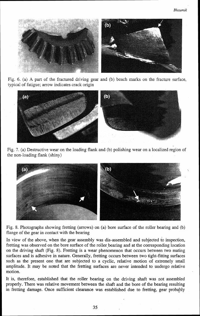
Fig. 4. (a) A part of the fractured driving gear and (b) beach marks on the fracture surface, typical of fatigue; arrow indicates crack origin
Fig. 7. (a) Destructive wear on the loading flank and (b) polishing wear on a localized region of the non-loading flank (shiny)
Fig. 8. Photographs showing fretting (arrows) on (a) bore surface of the roller bearing and (b) flange of the gear in contact with the bearing
In view of the above, when the gear assembly was dis-assembled and subjected to inspection, fretting was observed on the bore surface of the roller bearing and at the corresponding location on the driving shaft (Fig. 8). Fretting is a wear that occurs between two mating surfaces and is adhesive in nature. Generally, fretting occurs between two tight-fitting surfaces such as the present one that are subjected to a cyclic, relative motion of extremely small amplitude. It may be noted that the fretting surfaces are never intended to undergo relative motion.
It is, therefore, established that the roller bearing on the driving shaft was not assembled properly. There was relative movement between the shaft and the bore of the bearing resulting in fretting damage. Once sufficient clearance was established due to fretting, gear probably

Faiigue failure in aeroengine components
began pounding (low amplitude) on the driven gear causing excessive load on the teeth. This in turn had resulted in excessive wear on the loading flank as well as fatigue failure of the gear.
2.4. Failure of Connecting Rod of a Piston Engine: Operational Error
Failures are also caused by abuses in service. Many a failure has been witnessed when products were abused without recognizing the serious consequences. The following is an example. There were a series of accidents to a type of aircraft. The aircraft was fitted with six-piston engine and all the accidents were reported to have taken place due to engine failure. The failures were identical and in each case, one of the six connecting rods was found fractured into pieces (Fig. 9a), while there were no significant damages to the remaining five connecting rods. Fractographic examination confirmed that the connecting rod had failed by fatigue (Fig. 9b). Four fatigue cracks had initiated at the bolt cut out surfaces near the big cap and had progressed simultaneously over a period of time. Once these cracks had reached critical lengths, the big cap of the connecting rod had detached leading to extensive damage to the engine. One of the attachment bolts of the big cap had fractured into two pieces under bending overload. The other attachment bolt had fractured into three pieces on impact and the shank of the bolt could not be retrieved from the wreckage. A detailed study of the failed connecting rod was carried out to establish the sequence of failure in the engine. It was found that though there were four fatigue cracks at the four comers of the web of the connecting rod, one side of the web gave away first resulting in the lifting up of the big cap. It was conclusively proved that the attachment bolts were properly tightened and they had no role to play in the failure. Detailed investigation showed that the connecting rod failure was because of inadequate lubrication arising from loss of oil pressure. The loss of oil pressure was traced to faulty flying of the aircrafts. Following this investigation, the flying syllabus was revised and the problem was solved.
Fig. 9. (a) Fractured connecting rod and (b) fatigue crack origins (arrows) at comers of the web
2.5. Failure of Bearing in a Supercharger Gearbox of an Aeroengine: Adhoc Modification
Failures in components can result from inadequacies in design. Such inadequacies can be introduced inadvertently in the original design itself or in any modification carried out during service.
There was an incidence of bearing failure in the supercharger gearbox of an aeroengine. It was a roller bearing. Examination showed that many of the rollers were heavily damaged and had got kneaded to spherical shape (Fig. 10). These bearings were lubricated by a jet of oil. There had been a modification in the design of the locking cup washer and all the failures had occurred in the post-mod version. Examination of the drawing revealed that to avoid fatigue crack initiation, the passage meant for lubrication was blocked by welding (Fig. 11). As a result of modification, the bearings had suffered lubricant starvation leading to failure. This case amply illustrates the ill effects of ad-hoc alteration of design.

Fig. 10. Damaged bearing components
Pre - mod cup washer assembly Post - mod cup washer assembly
Fig. 11. Schematics showing (a) pre-mod and (b) post-mod cup washer assembly
3. Conclusions
It is now well recognized that failures do not just happen, but are caused. It has been shown that most of the fatigue failures of engine components can be attributed to the defects introduced mostly inadvertently during various stages of manufacturing. Design deficiencies, improper assembly and improper maintenance account for a sizable fraction of the total failures.
Acknowledgements
The failure cases presented in this paper were analyzed by the Failure Analysis and Accident Investigation Group at the Materials Science Division of National Aerospace Laboratories, Bangalore. The author is thankful to Director, NAL, for permission to publish this work.
References
1. S.J. Findlay and N.D. Harrison, "Why aircraft fail?", Materials today, November, 2002, pp.18 - 25
2. Metals Handbook, Failure Analysis and Prevention, 10, American Society for Metals, Metals Park, Ohio, 1975
3. V. Rarnachandran, A.C. Raghuram, R.V. Krishnan and S.K. Bhaumik, Failure Analysis of Engineering Structures: Methodologies and Case Histories, ASM International, Metals Park, Ohio, 2005