fatin izyani mohamad fazli - core.ac.uk · powder annealed at 500 ºc for 3 hours with the...
TRANSCRIPT

FABRICATION OF TITANIUM DIOXIDE THIN
FILM PREPARED BY SPRAY PYROLYSIS
DEPOSITION METHOD FOR DYE-SENSITIZED
SOLAR CELL
FATIN IZYANI MOHAMAD FAZLI
UNIVERSITI TUN HUSSEIN ONN MALAYSIA

FABRICATION OF TITANIUM DIOXIDE THIN FILM PREPARED BY SPRAY
PYROLYSIS DEPOSITION METHOD FOR DYE-SENSITIZED SOLAR CELL
FATIN IZYANI MOHAMAD FAZLI
A thesis submitted in
fulfillment of the requirement for the award of the
Degree of Master in Electrical Engineering
Faculty of Electrical and Electronic Engineering
Universiti Tun Hussein Onn Malaysia
2017

iii
This thesis was dedicated to my parents; Mohd Fazli Kamaruddin and Nor Aziah
Ahmad, my siblings and my family

iv
ACKNOWLEDGEMENT
I would like to express my earnest appreciation to my supervisor, Assoc. Prof. Dr.
Mohd Khairul Ahmad, for his continuous support, encouragement and patience
throughout this entire research work.
Special thanks are given to Microeletronics & Nanotechnology - Shamsuddin
Research Centre (MiNT-SRC), Universiti Tun Hussein Onn Malaysia (UTHM) for
aiding in technical and financial support. I would also like to acknowledge all MiNT-
SRC technicians, Mrs. Faezahana and Ms. Isrihetty, my friends and labmates, Mrs.
Sakinah, Mrs. Kamalia, Ms. Asyikin, Salina, Luqman, Kim Seng and Liyana for
showing me the ropes and sharing their knowledge. I would also like to express my
thankfulness for understanding parents, siblings and family members for always
supporting me all the way to the submission of this thesis.
Finally, I wish to express my deepest appreciation to Universiti Tun Hussein
Onn Malaysia for the opportunity to further my studies and for giving me a place to
learn and expand my knowledge.
.

v
ABSTRACT
Nanostructured Titanium dioxide (TiO2) thin films with the area of 0.25cm2 were
successfully fabricated on Fluorine-doped tin oxide (FTO) substrate on glass for dye
sensitized solar cell (DSSC) application using spray pyrolysis deposition (SPD)
method. The performance of each sample depend on the surface morphology,
structure and thickness of the samples. The TiO2 thin film was fabricated using P25
TiO2 nanopowder which is a combination of anatase and rutile structure, to have
different thickness ranging from 5 µm to 20 µm by varying the TiO2 colloidal
solution of 5 ml, 10 ml, 15 ml and 20 ml to find the optimum thickness for DSSC
application. Field Emission Scanning Electron Microscopy (FESEM) analysis on the
samples showed that the 5 ml sample with thickness of 2.379 µm is too thin that the
FTO structure underneath is visible. The sample with the highest efficiency of 1.677
% and 2.633 mA/cm2 Jsc is yielded by 10 ml sample. Further optimization for the
annealing temperature is done by varying the annealing temperature from 300 ºC to
500 ºC at fixed annealing time of 3 hours. Optimized annealing temperature is 500 ºC
with 3.42 % efficiency and 5.359 mA/cm2 Jsc. The annealing time was also varied to
from 1 hour to 24 hours. The structural analysis of the samples showed that the rutile
structure increased as the annealing time increased. The optimum annealing time is
proven to be 3 hours with 4.034 % efficiency and 5.937 mA/cm2 Jsc. TiO2 samples
fabricated by using pure anatase structure were also analyzed and compared to the
samples fabricated using P25. The annealing temperature for the pure anatase
samples was varied from 300 ºC to 500 ºC. The efficiency of the P25 is slightly
higher than pure anatase TiO2 which has the highest efficiency of 3.249 % annealed
at 500 ºC. The optimum TiO2 is the one fabricated with the P25 TiO2 powder
annealed at 500 ºC for 3 hours with the ruthenium based N719 dye as sensitizers.

vi
ABSTRAK
Filem nipis nanostruktur TiO2 dengan kawasan 0.25cm2 telah berjaya dihasilkan di
atas substrat FTO di atas kaca untuk aplikasi sel solar peka pewarna (DSSC)
menggunakan kaedah semburan pirolisis (SPD). Prestasi setiap sampel bergantung
kepada permukaan morfologi, struktur dan ketebalan sampel. Filem nipis TiO2 telah
dihasilkan menggunakan serbuk nano TiO2 P25 yang merupakan gabungan struktur
anatase dan rutil, untuk mempunyai ketebalan yang berbeza dari 5μm hingga 20μm
dengan mengubah isipadu koloid TiO2; 5 ml, 10 ml, 15 ml dan 20 ml untuk mencari
ketebalan yang optimum bagi aplikasi DSSC. Analisis FESEM ke atas sampel
menunjukkan bahawa sampel 5 ml dengan ketebalan 2.379 µm adalah terlalu nipis
sehingga struktur FTO di bawahnya boleh dilihat. Sampel optimum adalah sampel 10
ml dengan kecekapan 1.677 % dan 2.633 mA/cm2 Jsc. Proses optimum tambahan
bagi suhu penyepuhlindapan dilakukan dengan mengubah suhu penyepuhlindapan
daripada 300 ºC ke 500 ºC dengan masa penyepuhlindapan tetap selama 3 jam. Suhu
penyepuhlindapan optimum adalah 500 ºC dengan kecekapan 3.42 % dan Jsc 5.359
mA/cm2. Masa penyepuhlindapan juga telah dikaji untuk 1 jam hingga 24 jam.
Analisis struktur sampel menunjukkan bahawa struktur rutil meningkat jika masa
penyepuhlindapan meningkat. Masa penyepuhlindapan optimum terbukti 3 jam
dengan kecekapan 4.034 % dan 5.937 mA/cm2 Jsc. Sampel TiO2 juga dihasilkan
dengan menggunakan struktur anatase tulen dan dianalisis serta dibandingkan dengan
sampel yang dihasilkan menggunakan P25. Suhu penyepuhlindapan bagi sampel
anatase diubah daripada 300 ºC ke 500 ºC. Kecekapan sampel P25 adalah lebih
tinggi daripada anatase TiO2 tulen yang menghasilkan kecekapan 3.249 %. TiO2
optimum adalah yang dihasilkan dengan serbuk TiO2 P25 disepuhlindap pada 500 ºC
selama 3 jam dengan pewarna berdasarkan ruthenium N719 sebagai pemeka.
vii
TABLE OF CONTENTS
DECLARATION ii
DEDICATION iii
ACKNOWLEDGEMENT iv
ABSTRACT v
ABSTRAK vi
TABLE OF CONTENTS vii
LIST OF TABLES x
LIST OF FIGURES xi
LIST OF SYMBOLS AND ABBREVIATIONS xiv
LIST OF APPENDICES xv
LIST OF PUBLICATIONS xvi
CHAPTER 1 INTRODUCTION 1
1.1. Solar cell technology 1
1.2. Background of study 3
1.3. Problem statement 5
1.4. Hypothesis 5
1.5. Objectives 6
1.6. Project scopes 6
CHAPTER 2 LITERATURE REVIEW 7
2.1. Dye sensitized solar cell (DSSC) 7
2.2. Transparent conducting oxide (TCO) 10
2.3. Dye sensitizers 11
2.3.1. Synthetic dyes 11
2.3.2. Organic dyes 13
2.4. Electrolytes 14
2.5. Counter electrode 15
2.6. Titanium dioxide nanostructures 16

viii
2.7. Fabrication method 18
2.7.1. Spray pyrolysis deposition (SPD) method 20
2.8. Summary 23
CHAPTER 3 METHODOLOGY 24
3.1. Substrate preparation 24
3.2. TiO2 solution 26
3.2.1. Varying TKC-303 solution & pure anatase TiO2
(Sigma-Aldrich) 27
3.3. Deposition of TiO2 thin films 28
3.4. Annealing of TiO2 thin films 28
3.5. Dye and electrolyte preparations 29
3.6. DSSC assembly 30
3.7. Characterization of TiO2 thin film 32
3.7.1. Field emission scanning electron microscopy
(FESEM) 32
3.7.2. X-ray diffractometer (XRD) 33
3.7.3. Solar simulator 34
3.7.4. UV-Vis spectrophotometer 36
3.8. Summary 37
CHAPTER 4 RESULTS AND DISCUSSION 38
4.1. Effect of varying thickness to the optical and
structural properties of TiO2 thin films and its
performance in a DSSC
38
4.1.1. Surface morphology 38
4.1.2. Thickness 41
4.1.3. Optical properties 41
4.1.4. Structural analysis 43
4.1.5. Power conversion efficiency measurement 45
4.2. Effect of annealing temperature on the structural
properties of TiO2 thin films and its performance in
a DSSC 46
4.2.1. Surface morphology 47
4.2.2. Structural analysis 49
4.2.3. Power conversion efficiency measurement 50
4.3. Effect of annealing time on the structural properties
of TiO2 thin films and its performance in a DSSC 52

ix
4.3.1. Surface morphology 52
4.3.2. Structural analysis 55
4.3.3. Power conversion efficiency measurement 56
4.4. Effect of annealing temperature on the structural
properties of TiO2 thin films and its performance in a
DSSC using pure anatase TiO2 (Sigma-aldrich,
anatase > 99.7 %) 58
4.4.1. Surface morphology 58
4.4.2. Structural analysis 60
4.4.3. Power conversion efficiency measurement 62
4.5. Summary 64
CHAPTER 5 CONCLUSION 65
5.1. Conclusion 65
5.2. Future works 66
REFERENCES 67
APPENDIX 74
VITAE 75

x
LIST OF TABLES
4.1 Crystallite size of TiO2 thin film based on different
volume of TKC.
44
4.2 I-V measurements of DSSC using TiO2 thin film with
different volume of TKC.
46
4.3 Crystallite size of TiO2 thin film based on different
annealing temperature.
50
4.4 I-V measurements of DSSC with TiO2 samples annealed
at different temperatures.
52
4.5 Crystallite size of TiO2 thin film based on different
annealing time.
56
4.6 I-V measurements of DSSC with TiO2 samples annealed
at different annealing time.
58
4.7 Crystallite size of TiO2 thin film (Sigma-Aldrich, anatase
99.7%) based on different annealing temperature.
61
4.8 I-V measurements of DSSC with TiO2 samples annealed
at different temperatures.
64

xi
LIST OF FIGURES
1.1 Generations of solar cell technology. 2
2.1 Layers of DSSC components. 8
2.2 A schematic diagram of a DSSC showing the principles of
operation.
9
2.3 Structures of the ruthenium-based dyes N3, N719 and
‘black dye’ developed by the Grätzel group.
12
2.4 Structures of common anthocyanidins found in natural
foods.
14
2.5 Classification of electrolytes for DSSC. 15
2.6 Unit cells of the TiO2 modifications rutile, brookite and
anatase (from left to right).
17
2.7 TiO2 fabrication methods. 19
2.8 An illustration of spray pyrolysis deposition technique. 21
2.9 Illustration of the deposition process with increasing
substrate temperature.
22
3.1 Flow chart of the methodology. 25
3.2 Flow chart of the FTO substrate cleaning process. 26
3.3 FTO substrate with aluminium mask. 26
3.4 (a) TiO2 solution grinded in a mortar. (b) Lightproof bottle
with lid for ultrasonication.
27
3.5 (a) TiO2 deposition by SPD method. (b) Deposited TiO2 on
masked and unmasked substrates.
28
3.6 TiO2 samples after annealing process in a furnace. 29
3.7 TiO2 immersed in dye. 30
3.8 (a) TiO2 photoanode and Pt counter electrode is clamped
together on one side. (b) Electrolyte is inserted in between
the electrodes through a dropper. (c) The electrodes are
31
xii
clamped on the other side to make a complete DSSC.
3.9 Field Emission Electron Microcopy (FESEM). 32
3.10 Principle of X-Ray Diffraction Spectroscopy (XRD). 34
3.11 Solar Simulator. 35
3.12 UV-Visible Spectrophotometer (UV-Vis). 37
4.1 FESEM images of TiO2 with different amount of TKC (a)
5 ml, (b) 10 ml, (c) 15 ml and (d) 20 ml at 5, 000x
magnification.
39
4.2 FESEM images of TiO2 with different amount of TKC (a)
5 ml, (b) 10 ml, (c) 15 ml and (d) 20 ml at 25, 000x
magnification.
40
4.3 A graph of TKC-303 volume vs. TiO2 film thickness 41
4.4 Optical transmittance spectra of TiO2 films with (a) 20 ml
TKC, (b) 15 ml TKC, (c) 10 ml TKC and (d) 5 ml TKC.
43
4.5 XRD pattern of TiO2 thin film with different volume of
TKC.
44
4.6 Current density – voltage graph for the efficiency of DSSC
using TiO2 thin film with different volume of TKC.
46
4.7 FESEM images of TiO2 (a) as deposited, and annealed at
different temperatures (b) 300 ºC, (c) 400 ºC and (d) 500
ºC at 5, 000x magnification.
47
4.8 FESEM images of TiO2 (a) as deposited, and annealed at
different temperatures (b) 300 ºC, (c) 400 ºC and (d) 500
ºC at 25, 000x magnification.
48
4.9 XRD spectra of TiO2 thin films annealed at different
temperatures.
49
4.10 Current density – voltage graph of DSSC with TiO2
samples annealed at different temperatures.
51
4.11 FESEM images of TiO2 (a) as deposited, and annealed at
different duration (b) 1 hour, (c) 3 hours, (d) 10 hours and
(e) 24 hours at 5, 000x magnification.
53
4.12 FESEM images of TiO2 (a) as deposited, and annealed at
different duration (b) 1 hour, (c) 3 hours, (d) 10 hours and
54

xiii
(e) 24 hours at 25, 000x magnification.
4.13 XRD spectra of TiO2 thin films annealed for different time
duration.
55
4.14 Current density – voltage graph of DSSC with TiO2
samples annealed at different time durations.
57
4.15 FESEM images of TiO2 (Sigma-Aldrich) (a) as deposited
and annealed at (b) 300 ºC, (c) 400 ºC and (d) 500 ºC under
5,000x magnification.
59
4.16 FESEM images of TiO2 (Sigma-Aldrich) (a) as deposited
and annealed at (b) 300 ºC, (c) 400 ºC and (d) 500 ºC under
25, 000x magnification.
60
4.17 XRD pattern of TiO2 thin film using TiO2 anatase powder
(Sigma-Aldrich, anatase 99.7%).
61
4.18 Current density – voltage graph of DSSC with TiO2
samples (Sigma-Aldrich, anatase 99.7%) annealed at
different temperatures.
63
4.19 Comparison of current density – voltage graph of DSSC
with TiO2 samples using pure anatase and P25 nanopowder
annealed at different temperatures.
63

xiv
LIST OF SYMBOLS AND ABBREVIATIONS
AgBr - Silver bromide
AgCl - Silver chloride
CdTe - Cadmium telluride
CIGS - Copper indium gallium selenide
Cu2O
CVD
-
-
Copper oxide
Chemical vapor deposition
DMPII - 1,2-dimethyl-3-propyl-imidazolium iodide
DSSC - Dye sensitized solar cell
FESEM - Field Emission Scanning Electron Microscopy
FF - Fill factor
FTO - Fluorine doped tin oxide
Jsc - Current density
Nb2O5 - Niobium pentoxide
Pt - Platinum
Ru - Ruthenium
SnO2 - Tin oxide
SPD - Spray pyrolysis deposition
TCO - Transparent conducting oxide
TiO2 - Titanium Dioxide
UV-Vis - Ultraviolet-Visible Spectrophotometer
Voc - Open circuit Voltage
XRD - X-ray Diffraction
ZnO - Zinc oxide
𝜂 - Power conversion efficiency

xv
LIST OF APPENDICES
APPENDIX TITLE PAGE
A.1 Gantt chart of Research Activities 60

xvi
LIST OF PUBLICATIONS
1 Fatin Izyani Mohd Fazli, Nafarizal Nayan, Mohd Khairul Ahmad, Noor
Sakinah Khalid, Noor Kamalia Abd Hamed, Muhammad Luqman Mohd
Napi. “Effect of Annealing Temperature on TiO2 Thin Film Prepared by
Spray Pyrolysis Deposition Method.” Proceeding of Conference on Nano-&
Biosource Technology 2015 (NBT 2015), UKM Bangi, Selangor, 28-29
February 2015 (Sains Malaysiana Volume 45, No. 8 (August 2016), pg. 1197
– 1200).
2 Fatin Izyani Mohd Fazli, Ahmad Naim Suhaimi, Noor Sakinah Khalid,
Noor Kamalia Abd Hamed, Muhammad Luqman Mohd Napi, Salina
Mohamad Mokhtar, Ng Kim Seng, Nurfarina Zainal, Nafarizal Nayan, Soon
Chin Fhong, Mohd Khairul Ahmad, Suriani Abu Bakar, Azmi Mohamed.
“The Effects of Annealing Temperature on the Properties of Aluminium
Doped Tin Oxide (Al/SnO2) Thin Films Deposited by Spray Pyrolysis
Deposition (SPD) Method” Proceeding of Malaysian Technical Universities
Conference on Engineering and Technology 2015, KSL Resort Hotel, Johor
Bharu, 11 October-13 October 2015, ARPN Journal of Engineering and
Applied Sciences (JEAS).
3 Fatin Izyani Mohamad Fazli, Soon Chin Fhong, Nafarizal Nayan, Suriani
Abu Bakar, Azmi Mohamed, Mohamad Hafiz Mamat, Mohd Firdaus Malek,
Masaru Shimomura, Kenji Murakami. “Dye-sensitized Solar Cell using Pure
Anatase TiO2 Annealed at Different Temperatures” Optik – International
Journal for Light and Electron Optics. (Accepted)
4 Noor Kamalia Abd Hamed, Nafarizal Nayan, Mohd Khairul Ahmad, Noor
Sakinah Khalid, Fatin Izyani Mohd Fazli, Muhammad Luqman Mohd Napi.
“Influence of Hydrochloric Acid Volume on Titanium Dioxide (TiO2) Thin
Film by Using Hydrothermal Method.” Proceeding of Conference on Nano-&
Biosource Technology 2015 (NBT 2015), UKM Bangi, Selangor, 28-29

xvii
February 2015 (Sains Malaysiana Volume 45, No. 11 (November 2016), pg.
1669–1673).
5 Noor Sakinah Khalid, Fatin Izyani Mohd Fazli, Noor Kamalia Abd Hamed,
Muhammad Luqman Mohd Napi, Chin Fhong Soon, Mohd Khairul Ahmad.
“Biocompatibility of TiO2 Nanorods and Nanoparticles on Hela Cells.”
Proceeding of Conference on Nano-& Biosource Technology 2015 (NBT
2015), UKM Bangi, Selangor, 28-29 February 2015 (Sains Malaysiana
Volume 45, No. 11 (November 2016), pg. 1675–1678).
6 Muhammad Luqman Mohd Napi, Nafarizal Nayan, Mohd Khairul Ahmad,
Fatin Izyani Mohd Fazli, Noor Kamalia Abd Hamed. “Fabrication of
Fluorine Doped Tin Oxide with Different Volume of Solvents on FTO Seed
Layer by Hydrothermal Method” Proceeding of Conference on Nano-&
Biosource Technology 2015 (NBT 2015), UKM Bangi, Selangor, 28-29
February 2015 (Sains Malaysiana Volume 45, No. 8 (August 2016), pg. 1207
– 1211).
7 Noor Sakinah Khalid, Indah Fitriani Hamid, Noor Kamalia Abd Hamed,
Fatin Izyani Mohd Fazli, Soon Chin Fhong, Mohd Khairul Ahmad.
“Application of TiO2 Nanostructure Using Hydrothermal Method For Waste
Water Treatment.” Proceeding of International Conference on Electrical and
Electronic Engineering 2015 (IC3E2015), Equatorial Hotel, Melaka, 10-11
August 2015 (pending publication in ARPN Journal of Engineering and
Applied Sciences with Scopus indexed).
8 Muhammad Luqman Mohd Napi, M.F. Maarof, Soon Chin Fhong, Nafarizal
Nayan, Fatin Izyani Mohd Fazli, Noor Kamalia Abd Hamed, Salina
Mohamad Mokhtar, Ng Kim Seng, Mohd Khairul Ahmad, Suriani Abu
Bakar, Azmi Mohamed. “Fabrication of Fluorine Doped Tin Oxide (FTO)
Thin Films Using Spray Pyrolysis Deposition Method for Transparent
Conducting Oxide” Proceeding of Malaysian Technical Universities
Conference on Engineering and Technology 2015, KSL Resort Hotel, Johor
Bharu, 11 October-13 October 2015, ARPN Journal of Engineering and
Applied Sciences (JEAS).
9 Salina Mohamad Mokhtar, Mohd Khairul Ahmad, N.M.A.N. Ismail,
Mohamad Hafiz Mamat, Fatin Izyani Mohd Fazli, Noor Kamalia Abd
xviii
Hamed, Muhammad Luqman Mohd Napi, Noor Sakinah Khalid, Ng Kim
Seng, Nurfarina Zainal, Soon Chin Fhong, Suriani Abu Bakar, A.
Muhammad. “Fabrication of Co/SnO2 on Glass Substrate Using Spray
Pyrolysis Deposition Technique with Variation of Annealing Temperature”
Proceeding of Malaysian Technical Universities Conference on Engineering
and Technology 2015, KSL Resort Hotel, Johor Bharu, 11 October-13
October 2015, ARPN Journal of Engineering and Applied Sciences (JEAS).
10 Muhammad Luqman Mohamad Napi, Fatin Izyani Mohamad Fazli, Soon
Chin Fhong, Nafarizal Nayan, Suriani Abu Bakar, Azmi Mohamed,
Mohamad Hafiz Mamat, Masaru Shimomura, Kenji Murakami. “A facile
method for nanorice/nanospherical fluorine doped tin oxide using
hydrothermal method for Dye-sensitized solar cell application” Ceramics
International. (In review)

xix

1
CHAPTER 1
INTRODUCTION
This chapter introduces the Dye-Sensitized Solar Cell (DSSC) and the history of its
findings. Recent advances are also mentioned and continued in chapter 2. The problem
statement, objectives and scopes of this study is stated in this chapter.
1.1. Solar cell technology
Solar cells are also known as a type of photovoltaic device which basically converts
light or photon energy to electrical currents. The concept of the working principle of
solar cells is similar as photosynthesis in plants [1]. Solar cells are considered as an
attractive alternative for an energy source for its minimal impact on environment and
sustainability [2].
There are three generations or categories of solar cells as summarized in Figure
1.1. The first generation is the silicon solar cells. The first generation of solar cells is
defined by their silicon wafer base. This generation of solar cell is the most commonly
used on building rooftops despite the high manufacturing cost that came with the use of
silicon wafers. Even when the materials used are expensive, this type of solar cell
generates the highest conversion efficiency with the average of 15-25 % [3][4]. This
generation of solar cell also has high stability [5].

2
Figure 1.1: Generations of solar cell technology.
The second generation of solar cell features thin film solar cells made with
amorphous silicon, copper indium gallium selenide (CIGS) and cadmium telluride
(CdTe) which can be made to be far more flexible than the first generation with
significantly lower cost for materials used; though the manufacturing of this type of
solar cells still require high temperature treatment and vacuum processes, which are
energy consuming [6–8].
The third generation of solar cells are not as commercially available as the first
and second generation of solar cells and are mainly still in the process of improvements
under laboratory conditions. Dye sensitized solar cells (DSSCs) are an example from
this generation. The main objective of this generation is to provide a lower cost of solar
cells that are also efficient over a wider band of photon energy [9, 10]. Third generation
solar cells feature a lot of materials other than silicon with a variety of different
structures other than using more conventional fabricating methods in order to complete
its objective [11, 12].
Solar cell technology
1st generationClassic silicon (poly/single
crystal)
2nd generation
Amorphous silicon
Thin film (CIGS, CdTe)
3rd generation
Polymers
DSSC

3
1.2. Background of study
The nonrenewable energy sources are rapidly diminishing, thus leading to studies on
renewable energy around the world. Solar cells come as the leading choice for this
purpose. A great alternative choice for the current solar cell would be the dye-sensitized
solar cell (DSSC) for it is effective in both cost and conversion efficiency. In 1839, the
photovoltaic (PV) effect was discovered by a French physicist, Alexandre-Edmond
Becquerel which opened the door to solar cell technology. Becquerel's experiment was
conducted by illuminating two electrodes coated by light sensitive materials, AgCl or
AgBr, using different types of light. The electricity was found increased as the light
intensity increased. Charles Fritts constructed what was probably the first true solar cell
in 1894. He coated selenium which is a semiconductor material with a very thin layer of
gold. The efficiency of the device was only about 1% and couldn't be used as an energy
supply, but were later used as light sensors. In 1954, three researchers, Gerald Pearson,
Daryl Chapin and Calvin Fuller [13] of Bell Laboratories discovered the silicon solar
cell, which was the first material to directly convert enough sunlight into electricity to
run electrical devices. The efficiency of the silicon solar cell was 4%, which later
increased to 11%. The cells were made by hand and cost $1000 per watt. Nowadays, the
silicon solar cells are known to yield an efficiency of more than 40% [14], which is
remarkable considering its inexhaustible source. The theory of using illuminated dye
molecules to generate electricity was further employed in a research conducted by
Gerischer [15] as an effort in lowering the cost of photovoltaic devices. Further
researches were done on how to improve the efficiency and stability of the DSSC. In
1991, modern type DSSC was co-invented by Michael Grätzel and Brian O’Regan [16]
at UC Berkeley and was also called Grätzel cell with the efficiency of 7.1% to 7.9%.
A part that contributes to the general function of a DSSC is a metal oxide
semiconductor thin film that acts as a charge collector and a base for sensitizer
molecules to be adsorbed onto. The most commonly employed oxide for the purpose of
DSSC is TiO2, other than ZnO, Cu2O, SnO2 and Nb2O5 for their stability due to their
wide band gap and also for their photocatalytic properties. Other than photovoltaic

4
devices, TiO2 is also known to have a role in gas sensors [17], display devices [18],
photo-induced water splitting [19], waste water treatment [20] and even in paint [21].
Many researches have been done to improve the efficiency and overall stability
of DSSC [22]. The most advanced and recent DSSC is achieved with the highest
conversion efficiency of 13% [23]. This is a very huge finding in the history of DSSC.
This high efficiency is caused by an efficient semiconductor thin film; the dye and
electrolyte used also plays a large part in increasing the electron mobility and the current
flow [24, 25].
Some of the properties of TiO2 can be improved as to boost the efficiency of the
DSSC. For example, an increment of the surface area of TiO2 thin film will allow for
more dye molecules to be adsorbed, thus adding to the number of electron released from
the dye under illumination [26]. One can increase the surface area of the thin film by
constructing the TiO2 molecules in the form of nanoflowers [27], nanorods [28],
nanotubes [29] or nanowires [30]. Another means to increase the surface area is to
increase the porosity of the thin film as to be done in this study.

5
1.3. Problem statement
Photoelectrons must travel a distance before reaching the transparent conducting
oxide (TCO) layer. If the distance is too long, the photoelectrons can lose energy and
fall back to ground state. It is important that the TiO2 layer is not too thick that the
photoelectrons will recombine. On the other hand, if the TiO2 layer is too thin, there
may not be enough TiO2 particles for the dye to attach onto which will result in
lower dye adsorption. Low dye adsorption will then result in lower current density
due to lower amount of photoelectrons. The main focus in attempts on improving the
TiO2 thin film is to increase dye adsorption and electron mobility. Annealing of TiO2
samples can produce a more pure sample with better crystallinity and electron
mobility but high temperatures can also result in the necking of particles which will
reduce surface area for dye adsorption. The TiO2 thin film used should have an
optimum thickness and annealed at an optimum temperature to achieve the highest
efficiency.
1.4. Hypothesis
Increasing the thickness of photoanode might lower the tranmittance of the film, thus
reducing incident light to be absorbed by the dye molecules [31]. Thick TiO2 film
will also increase the chances of recombination of the photoelectrons [32]. The
efficiency of a DSSC strongly depends on the surface morphology and electronic
properties of the photoanode with thickness ranging from a few hundred nanometers
up to 20 µm [33]. Annealing process can eliminate excessive solvent and impurities
which can increase electrically-connected link of TiO2 particles and affect the
thickness of the film [34]. Annealing can improve porosity of a film but high
temperatures can also result in necking of the particles [35]. Porosity of a film is
associated with annealing temperature and time duration, which will affect the
amount of dye adsorbed and photocurrent density [36]. Rutile on its own have poor
photocatalytic activity and is prone to recombination while anatase is far superior in
the application of DSSC. However, a synergistic effect between anatase and rutile
exists in mixed-phase TiO2 nanocomposites such as P25 that is supposed to enhance
the photocatalytic activity of anatase [37–39].

6
1.5. Objectives
The objectives of this study were as follows:
i. To investigate the surface morphology, structural property and efficiency
of TiO2 thin films in a DSSC fabricated by spray pyrolysis deposition
(SPD) method.
ii. To obtain the optimum thickness of the TiO2 thin film for the best optical
transmittance by varying the amount of TKC-303 (TiO2 colloid) solution.
iii. To increase the current density of fabricated DSSC by providing larger
surface area for dye adsorption on the TiO2 thin films through annealing
at different temperatures and annealing time duration.
1.6. Project scopes
The project were conducted in accordance to the following scopes:
i. Deposition of TiO2 thin films by spray pyrolysis deposition method using
a regular airbrush.
ii. Volume of TKC-303 solution is varied to be 5 ml, 10 ml, 15 ml and 20
ml.
iii. Annealing temperature is varied at 300 ºC, 400 ºC and 500 ºC.
iv. Annealing time duration is varied for 1 hour, 3 hours, 10 hours and 24
hours.
v. Measurement of thickness by using a surface profiler.
vi. Observations of the surface morphology of thin films using FESEM.
vii. Analysis on the crystal state and crystal structure by an XRD machine.
viii. Testing of DSSC efficiency by using the Solar Simulator.
ix. Optical properties analysis by UV-Vis Spectrophotometer.

7
2CHAPTER 2
LITERATURE REVIEW
This section discussed further about the DSSC and its components; the TiO2 film,
dye sensitizers, electrolyte and counter electrode. The SPD method is also discussed
including previous researches using the same method. The methods of
characterization were also mentioned in this chapter.
2.1. Dye sensitized solar cell (DSSC)
Solar cell with the highest conversion-efficiency would be a multi-junction solar cell
at more than 41 % [40] and there is still a new multi-junction solar cell said to be
able to exceed this limit. For a DSSC, the conversion-efficiency is not as high as
other types of solar cells used nowadays with 13 % efficiency being the highest. But
the fact that DSSCs use low cost materials with some of it can be readily found in
nature and also low production cost has put DSSC under attention in the photovoltaic
(PV) field.
DSSC differs from the conventional solar cells because it only uses one type
of semiconductor as can be seen in Figure 2.1, only for the purpose as a charge
carrier transport, while p-n junction solar cells uses two types of semiconductors for
light absorption and charge carrier transport. However, until now their overall
efficiency has been lower than silicon-based solar cells, mostly because of the innate
voltage loss duri ng the regeneration of the sensitizing dye [32, 33].

8
Figure 2.1: Layers of DSSC components.
The basic operational principle of a DSSC mimics the first stage of
photosynthesis in that they both use sunlight to convert the energy into chemical
energy which is then applied to something else. For DSSC, the photo-induced
electrons flow and generate current throughout the circuit. Figure 2.2 simplifies the
working process of a DSSC. The process starts when the photoanode absorbs an
incident solar energy (hv). Photo-excitation of the dye molecules, S will occur and
the excited electrons will be injected into the conduction band of the mesoporous
semiconductor material. The process is as shown below:
S + hv → S* (photoexcitation) (2.1)

9
Figure 2.2: A schematic diagram of a DSSC showing the principles of operation [43].
The electrons will flow through the mesoporous TiO2, to the collector
electrode which is the transparent conductive oxide, before travelling to the external
circuit through a load in a form of a current. When the electrons reach the counter
electrode/ cathode, redox triiodide electrolyte (3I−/I3−), which is in contact with both
the electrodes, will oxidize at the anode as they donate electrons to the oxidized dye
molecules thus reducing it back to its ground state:
2S+ + 3I− → 2S + I3− (regeneration of S) (2.2)
For the preparation of a DSSC, the anode component is deposited with a
several micron thickness of mesoporous TiO2 thin film. The particle size can
influence the effective surface area for dye adsorption, porosity and also the pore
volume for redox electrolytes to seep into the film [44]. The thin film can be really
translucent or opaque depending on the method and materials of preparation [45].
The thin film will act as a base for the adsorption of the dye molecule. Dye will be
adsorbed onto the TiO2 thin film by immersing the thin film into the dye solution for

10
an amount of time ranging from less than an hour to overnight [46]. The DSSC is
made by sandwiching the anode and cathode which is layered with a reflective,
electrocatalytic thin film with a few drops of redox electrolyte in between the
electrodes.
2.2. Transparent conducting oxide (TCO)
TCOs are electrically conductive oxide material with low level of light absorption.
For the application of DSSC, it is almost compulsory for the TCO to be almost fully
transmitting solar radiation with transmittance above 80 % in the visible to IR region.
The TCO is also required to have low sheet resistance (5-15 Ω/square), and
unaffected by the high temperatures of 400-500oC typically used to anneal TiO2
samples [47]. TCO in DSSCs acts as a current collector of the photoelectrons
channeled from the TiO2. Thus it is important for the TCO used to have excellent
conductivity to minimize the series resistance in the circuit for better conversion
efficiency.
Other than oxides such as Zinc Oxide (ZnO) and Tin Oxide (SnO2),
conductive polymers and metal grids and films also had been attempted to be used in
DSSCs [39-41]. While polymers are easy to fabricate and is flexible, and suitable
metals that can be used is relatively abundant, these two materials have their own
disadvantage as polymers are known to have lower electrical conductivity and
transmittance, while metal conducting films can be expensive and reactive towards
electrolytes used in DSSCs.
SnO2 is an n-type semiconductor often used in DSSCs for its wide band gap
(3.87 – 4.3 eV), transparency, good electron mobility and high donor concentration
for dopants. Indium-doped Tin Oxide (ITO) in one of the most commonly used TCO
in the applications of solar cells [51]. Even though ITO is outstanding in terms of
electrical conductivity and charge transfer, its drawback lies in its high cost and
limited resource other than expensive and tedious fabrication process. Therefore, as a
cheaper alternative but with a comparable efficiency, FTO is commonly used as
current collectors in DSSCs. SnO2 can also be doped with other materials such as
antimony and aluminum. However, using fluorine as dopant is superior in terms of
transparency in the visible light region and thermal stability.

11
2.3. Dye sensitizers
On the mesoporous semiconductor oxide layer, photosensitizers are adsorbed to be
illuminated by solar energy and excite electrons. Ever since the introduction of
DSSCs, thousands of different sizes and different compounds of molecules have
been tested as potential dyes. A few of desirable properties of dyes include strong
light absorption in the visible and near IR region for efficient light harvesting, good
solubility in organic solvents for easier deposition from stock solution onto oxide
layer, possesses suitable peripheral anchoring ligands such as COOH to attach more
effectively onto the oxide surface, having efficient electron injection into the
conduction band of oxide layer, good thermal and chemical stability for the repetitive
redox reactions. An ideal sensitizer for a PV cell converting standard air mass (AM)
1.5 sunlight into an electricity must absorb all light photons below a threshold
wavelength of about 900 nm, which is equivalent to a semiconductor with a bandgap
of 1.4 eV [52]. Basically, the dyes can be organic (e.g. porphyrins, phtalocyanines)
or inorganic (e.g. ruthenium complex) [53].
2.3.1. Synthetic dyes
The finest PV performance in terms of both conversion efficiency and long term
stability has so far been achieved by the Grätzel group with polypyridine complexes
of Ruthenium (Ru); N3, N719 and ‘black’ dyes [54] as shown in Figure 2.3. Other
than superior light harvesting properties and durability, a significant advantage of
these dyes is the effective metal-ligand charge transfer transition through which the
photoelectron is injected into TiO2. In 1993, Seigo Ito [55] published DSSCs with
10.3 % conversion efficiency using a ruthenium dye sensitizer (N3, [cis-
di(thiocyanato)bis(2,2-bipyridine-4,4- dicarboxylate)ruthenium]). In Ru complexes,
this metal-ligand transfer takes place at a much faster rate than the back reaction in
which the photoelectron recombines with the oxidized dye molecule rather than
flowing through the circuit.
Since the achievement of the 10.3 % conversion efficiency using the N3 dye,
it had been difficult for researchers to reproduce the efficiency. In 2001, Nazeeruddin
[56] reported DSSCs with 10.4 % efficiency by using a ruthenium dye called ‘black’

12
dye. Even when the black dye looks green in solvent, after it has been adsorbed on a
porous nanocrystalline TiO2 electrode, the DSSC looks black due to the wide
absorption band of the dye which covers the entire wavelengths in the visible range.
Subsequently, Wang [57] reported 10.5 % efficiency, and Chiba [58] reported 11.1
% efficiency, when using black dye. In 2005, Nazeeruddin [59] reported a new dye
which was similar to N3, N179, but achieved 11.2 % conversion efficiency in DSSC.
One of the differences between the two dyes is that N3 has four H+ counterions
whereas N719 has two TBA+ and two H+ counterions. The difference in the
counterions influences the speed of adsorption onto the TiO2 electrode; N3 is faster
(optimum adsorption time: 3h) whereas N719 is slower (optimum adsorption time:
24h).
Figure 2.3: Structures of the ruthenium-based dyes N3, N719 and ‘black’ dye
developed by the Grätzel group [54].
13
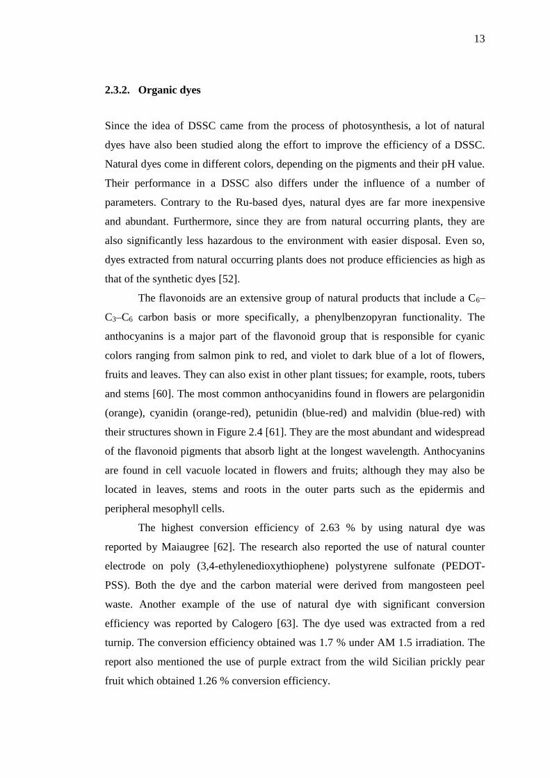
2.3.2. Organic dyes
Since the idea of DSSC came from the process of photosynthesis, a lot of natural
dyes have also been studied along the effort to improve the efficiency of a DSSC.
Natural dyes come in different colors, depending on the pigments and their pH value.
Their performance in a DSSC also differs under the influence of a number of
parameters. Contrary to the Ru-based dyes, natural dyes are far more inexpensive
and abundant. Furthermore, since they are from natural occurring plants, they are
also significantly less hazardous to the environment with easier disposal. Even so,
dyes extracted from natural occurring plants does not produce efficiencies as high as
that of the synthetic dyes [52].
The flavonoids are an extensive group of natural products that include a C6–
C3–C6 carbon basis or more specifically, a phenylbenzopyran functionality. The
anthocyanins is a major part of the flavonoid group that is responsible for cyanic
colors ranging from salmon pink to red, and violet to dark blue of a lot of flowers,
fruits and leaves. They can also exist in other plant tissues; for example, roots, tubers
and stems [60]. The most common anthocyanidins found in flowers are pelargonidin
(orange), cyanidin (orange-red), petunidin (blue-red) and malvidin (blue-red) with
their structures shown in Figure 2.4 [61]. They are the most abundant and widespread
of the flavonoid pigments that absorb light at the longest wavelength. Anthocyanins
are found in cell vacuole located in flowers and fruits; although they may also be
located in leaves, stems and roots in the outer parts such as the epidermis and
peripheral mesophyll cells.
The highest conversion efficiency of 2.63 % by using natural dye was
reported by Maiaugree [62]. The research also reported the use of natural counter
electrode on poly (3,4-ethylenedioxythiophene) polystyrene sulfonate (PEDOT-
PSS). Both the dye and the carbon material were derived from mangosteen peel
waste. Another example of the use of natural dye with significant conversion
efficiency was reported by Calogero [63]. The dye used was extracted from a red
turnip. The conversion efficiency obtained was 1.7 % under AM 1.5 irradiation. The
report also mentioned the use of purple extract from the wild Sicilian prickly pear
fruit which obtained 1.26 % conversion efficiency.

14
Figure 2.4: Structures of common anthocyanidins found in natural foods [61].
2.4. Electrolytes
The role of an electrolyte is to facilitate the transport of the electron between the
working electrode and the counter electrode. Electrolytes for DSSC can be classified
into 3 types; solid, liquid and quasi-solid as shown in Figure 2.5. A few ideal
properties of an electrolyte include low viscosity to ease electron diffusion, good
interfacial contact with the working and counter electrode, low vapor pressure to
ensure long term stability of the DSSC, high boiling point, and high dielectric
properties. Other important qualities include chemical inertness, environmental
sustainability and simple fabrication process.
A lot of redox electrolyte have been tested in the effort to find the best
electrolyte for DSSCs. The most favorable electrolyte found was the triiodide/iodide
couple. Various solvents have also been tested to achieve an electrolyte with the best
performance even under extreme conditions. For example, acetonitrile as solvent can
provide low viscosity for the electrolyte, but has low boiling point and high vapor
pressure; making it unable to withstand temperatures higher than 80oC.
The electrolyte used in this research is a type of liquid electrolyte. Liquid
electrolytes uses liquid solvents as a medium for the redox couple of the electrolyte.
Liquid electrolytes can be roughly divided into two; organic solvents as used in this
research, and ionic liquid electrolytes. One of the most common organic solvents

15
used is acetonitrile based on its efficiency as have been proven by Grätzel &
O’Regan [16], by mixing it with ethylene carbonate. While acetonitrile has low
viscosity and good solubility as it can dissolve a wide range of organic compounds
and salts, it is also volatile with high vapor pressure. Other nitriles such as
glutaronitrile, valeronitrile and propionitrile have also been studied alongside with
other organic solvents from alcohols to water. Two types of nitriles, 3-
methoxypropionitrile and butyronitrile were found to be less volatile than
acetonitrile, while also has higher boiling point and good performance stability. The
downside to these nitriles is that they have higher viscosity than acetonitrile and as a
result, it exhibits lower efficiencies.
Figure 2.5: Classification of electrolytes for DSSC [24].
2.5. Counter electrode
The counter electrode also known as cathode functions to reduce the oxidized form
of the electrolyte as it provides electrons flowing from the outer circuit. The cathode
component is usually lined with Pt for its good electrocatalytic properties, high
exchange current density and reflectivity. Though Pt is a rare and expensive
substance, only a small amount is needed to make a highly effective cathode [64]. Pt
Electrolyte
Solid state Liquid
Organic solventIonic liquid
Quasi-solid

16
also acts as a catalyst to accelerate the reduction reaction of the electrolyte. But due
to the high cost of Pt, other substances like graphene and conductive polymers are
also being used as alternative materials for the counter electrode [65].
2.6. Titanium dioxide nanostructures
Titanium dioxide (TiO2), also known as titania, exists in nature as an oxide of
titanium and is relatively abundant. It exists in a lot of different forms with the three
most accessible forms being rutile (tetragonal), anatase (tetragonal) and brookite
(orthorhombic). The basic structure of the three TiO2 forms are as shown in Figure
2.6. Rutile is the more thermodynamically stable form of TiO2 if compared to anatase
[66], though the fact is only for macroscopic crystals. For nanocrystals with sizes of
about 10-20 nm, anatase is the more stable form which regarding on their sizes, in
agreement with a research conducted to compare diamonds and graphite [67]. Rutile
can be produced synthetically by annealing anatase at the temperature of 700-1000
ºC since anatase is metastable [68]. Researches on brookite is not as much as the
ones on anatase and rutile because it is rare in nature and the synthesis of pure
brookite is difficult [69].
In the application of DSSC, anatase is a much more popular selection as a
photoanode due to high electron mobility and superior photocatalytic activities [70].
Since the anatase conduction band is more negative by 0.2 V than rutile, a higher
maximum photovoltage can be achieved by using anatase photoanode than rutile if
the same redox mediator is used [71]. However, there is also a theory that by mixing
anatase and rutile which has lower energy, the transfer of electrons from anatase
rutile electron trapping site helps to lessen the rate of recombination for anatase,
leading to more effective electron-hole separation and improved catalytic reactivity
[72]. However, the data used to support this theory is inconclusive and need further
research since there can be a lot of factors that can influence the synergistic effect
between anatase and rutile.

17
Figure 2.6: Unit cells of the TiO2 modifications rutile, brookite and anatase (from left
to right) [73].
TiO2 is used as a layer of electron acceptors for DSSC for its wide band gap
and thus, stability. The band gaps for rutile and anatase are 3eV and 3.2eV
respectively. The band gaps for both materials are indirect. Though there are other
oxide semiconductors that fit the role as well, TiO2 turns out to be the most versatile
for allowing the DSSC to have the highest solar conversion efficiency. TiO2 is also
very inert and non-reactive, non-toxic and readily available in huge quantities. One
of the applications of TiO2 is as pigments in white paints, for its brightness and very
high refractive index [74]. This property of TiO2 is also of use for other researches
for example, in antireflective coatings [75]. Thousands of publications have written
on the preparation of colloidal particles of TiO2 by the solvothermal reactions based
on titanium n-butoxide and acetic acid which can yield TiO2 of many morphologies
from nanoparticles [76], nanowires [77], nanofibers [78], nanosheets [79] and
nanotubes [80].
TiO2 naturally has high transport mobility of the charge carrier that reduces
the electron-transport resistance but its performance can be improved. Synthetic or
naturally occurring TiO2 are both slightly oxygen deficient, TiO2-x (x ≈ 0.01). This
small deficiency makes room for n-type doping which can reduce its band gap and
increase its photocatalytic properties [81]. Double layer structured TiO2 can increase
the transport mobility of the TiO2 film [82]. It is done by depositing an underlayer of
large size particles (200-300 nm) before a layer of nanoparticles (10-30 nm) on top.

18
This creates a larger surface area and better transport mobility at the same time. A
loss path in DSSC is the recombination of the injected electrons with the electrolyte.
The result of this phenomenon is the dark current, which diminishes the efficiency of
a DSSC. This situation can be prevented and minimized by modifying the structure
of TiO2. This modification can be employed by adding insulating or blocking layer,
and by treating the surface of the TiO2. The treatments can be classified into
mechanical or chemical method.
Chemical vapor deposition, chemical and electrochemical treatment, sol-gel
and biochemical are examples of chemical treatment method. This method involves
chemical reactions at the interface between the material and chemical used.
Mechanical treatment method includes etching, blasting, polishing, shaping and other
physical treatments. The main goal of this method is to obtain certain roughness and
topography aside from removing surface contaminants and improving adhesion
quality if necessary [83].
Annealing of TiO2 thin films, which can be included as one of the mechanical
treatments, can improve their surface morphology and crystallinity which can heavily
influence the electron transport rate and effective surface area [84]. Annealing
process evaporates the solvent used in the preparation of the thin film, resulting in
purer and more crystalline structure. The annealing process may affect the thickness
of the film but not necessarily as reported in a previous research [85]. Instead of
thinning the film, annealing process changes the structure of the film from
amorphous to a more porous and crystalline structure. It was also reported that
annealing of the films makes the grain size becomes larger, lowers the transmittance
of the film, increase the value of refractive index and allowed indirect optical band
gap [43]. Other than that, annealing process was also reported to make the surface
rougher as the temperature increase [86].
Annealing under the influence of oxygen and nitrogen gas can improve the
structure of the TiO2 thin films fabricated even more than annealing in air. Annealing
under the influence of nitrogen gas can add ligands on the surface of the TiO2
particles so that the dye molecules can attach better on the surface. This kind of
annealing gives an extra advantage on films for DSSC application. Annealing of
TiO2 in oxygen gas is much like doping in oxygen into the TiO2 structure. It can
increase the electron mobility of the TiO2 films.

19
2.7. Fabrication method
TiO2 thin film for DSSC can be fabricated to be in various shapes and sizes
depending on the methods and materials used as summarized in Figure 2.7. TiO2 can
be produced by using hydrothermal method [87], sputtering method [88], chemical
vapor deposition [89], doctor blading [90], pulsed laser deposition [91] and spray
pyrolysis deposition method [92], to name a few.
Figure 2.7: TiO2 fabrication methods.
Hydrothermal method is a method of crystallizing substances using a solution
heated in a closed system under a controlled pressure. The closed system frequently
used in previous researches is an autoclave. The pH of the solution, the temperature
and the pressure applied on the system can determine the shape of the crystals and
the phase; whether it is rutile or anatase. It was also reported that the formation of
pure brookite crystals is also possible by hydrothermal method [93].
Sputtering method is when atoms are ejected from a target bombarded by an
accelerated particle onto a substrate to create a thin film. The thickness of the thin
TiO2
fabrication methods
Hydrothermal method
Sol-gel
Sputtering
Pulsed laser
deposition
Chemical vapor
deposition
Spray pyrolysis
deposition

20
film is varied by the sputtering deposition time. Sputtering method is an effective
method to create Pt thin film for the counter electrode as it can create a minimum
thickness for a highly efficient counter electrode. Pulsed laser deposition method is
quite similar to the sputtering method except that it uses a pulsing laser to bombard
the target and not an energetic particle.
Chemical vapor deposition (CVD) is a chemical process used to produce high
quality and high-performance thin film. The substrate is exposed to one or more
volatile precursors, which react and decompose on the substrate surface to produce
the desired deposit. Frequently, volatile by-products are also produced, which are
removed by gas flow through the reaction chamber. Doctor blading or blade coating
is a method practiced in the making of thin film on a large surface area rigid or
flexible substrate. The thickness of the film is determined by the distance of the blade
to the substrate surface. It is a simple yet effective method of thin film deposition.
Spray pyrolysis deposition (SPD) is a liquid phase chemical deposition
method of a thin film involves the spraying of a solution onto substrates placed over
a heated surface where the solvent will evaporate to form a solid chemical
compound. The compound used to produce a thin film by this method should be
volatile at the temperature of deposition. SPD technique is one of the easiest and
cost-effective methods in the preparing thin films of different thickness, ceramic
coatings and powders. This method is suitable for a wide range of compositions and
often does not require special types of substrates. This method can also be employed
in the making of dense or porous films [81, 82], multi-layered films [96] and also
powder production [97].
2.7.1. Spray pyrolysis deposition (SPD) method
The schematic representation of SPD apparatus is shown in Figure 2.8. Typical SPD
equipment consists of an atomizer, a heater with a temperature controller, and a
solution that will come out of a nozzle. There are a few types of atomizer for SPD
technique; air blast or air compressor where the solution is exposed to a stream of air,
ultrasonic that produces short wavelengths for fine atomization and electrostatic
where the solution is exposed to high electric field. The substrate surface temperature
is important in determining the surface morphology of the resulting thin film. Higher

21
temperature can change the surface from dense to slightly cracked and then to a
porous structure. The surface structure of the film can influence its optical and
electrical properties [92].
Figure 2.8: An illustration of spray pyrolysis deposition technique.
An example of TiO2 by SPD method was performed by Masayuki Okuya
[98]. The source solution of titanium (IV) oxy acetylacetonate 2-butanol was
atomized by a nozzle with 3.0 kg/cm2 of compressed air. The mist was transported
onto a heated glass substrate (Corning 1737, 25mm x 25mm x 1mm in size) with the
distance between the nozzle and the glass substrate about 300 mm. The parameter of
this experiment is the substrate surface temperature which varied from 300 to 500 oC.
The film formation was carried out intermittently since the mist will cool down the
substrate temperature. When the substrate temperature was recovered, the process
was resumed. The spray rate of the solution and the period for each spraying was
fixed at 1.0 ml/s and 0.5 s respectively. The results of this research showed that the
samples obtained are anatase, though the samples deposited on substrate with surface
temperature of 300 oC are amorphous. The optimum surface temperature to grow
anatase by SPD method according to this research was 350 oC.
10cm

22
According to a paper discussing the SPD method by Perednis and Gauckler
[92], this method involves processes that occur either sequentially or simultaneously.
A few of the main processes involved aerosol generation and transport, droplet
impact and spreading, solvent evaporation and precursor decomposition. They also
stated that the temperature of the substrate will determine the morphology and
properties of the film fabricated [99]. Increasing the temperature of the substrate can
change the morphology of the film from dense or cracked to a more porous structure.
Figure 2.9 shows how the surface temperature will affect the precursor solution in
the deposition process.
Figure 2.9: Illustration of the deposition process with increasing substrate
temperature [92].

23
2.8. Summary
DSSC is a type of solar cell that produces a lower efficiency than a
conventional solar cell but it has a few attractive advantages in terms of cost and
minimal impact on the environment. TiO2 is a type of semiconductor that is most
popular to be used in a DSSC as a base for dye sensitizers and a photoanode. TiO2
can be fabricated in many ways but the SPD method is applied in this research for its
simple and low cost process next to the fact that it is versatile for the ability to
deposit on a wide range of surfaces. N719 dye is a type of synthetic ruthenium dye
famous for having a wide range of absorbance and thus selected and used in this
research. The electrolyte used is the triiodide redox electrolyte in acetonitrile solvent
for low viscosity and good solubility. Pt electrode is selected to be used for it is
known to have good conductivity, highly reflective and is inert when used with the
electrolyte.

24
3CHAPTER 3
RESEARCH METHODOLOGY
The TiO2 thin films are prepared by spray pyrolysis deposition method on fluorine-
doped tin oxide (FTO). The flow chart of the methodology is as in Figure 3.1. Four
sets of TiO2 thin films were fabricated with different parameters; TKC volume,
annealing temperature and time, and pure anatase TiO2. The films are then
characterized by using X-ray Diffractometer (XRD), Field Emission Scanning
Electron Microscopy (FESEM) UV-Vis Spectrophotometer (UV-Vis), Surface
Profiler and a Solar Simulator.
3.1. Substrate preparation
The substrate used in this study is the FTO on glass and was prepared according to
the steps listed in Figure 3.2. The dimension of the substrates is 2cm x 1cm. the
substrates are cleaned by an ultrasonicator in distilled water, ethanol and propanol
solution of the same ratio 1:1:1. The ultrasonic cleaning is done for 10 minutes with
the heat off. The cleaned substrates are then left in air to dry before masked by a
piece of punctured aluminum foil as shown in Figure 3.3 with the area of the hole
being 0.25 cm2. The substrates are then put onto a hotplate and was heated up to 150
oC. A total of 8 substrates are used for each deposition process.

67
REFERENCES
[1] I. McConnell, G. Li, and G. W. Brudvig, “Energy Conversion in Natural and
Artificial Photosynthesis,” Chem. Biol., vol. 17, no. 5, pp. 434–447, May
2010.
[2] L. M. Peter, “Towards sustainable photovoltaics: the search for new
materials,” Philos. Trans. R. Soc. London A Math. Phys. Eng. Sci., vol. 369,
no. 1942, 2011.
[3] M. Green, “The path to 25% silicon solar cell efficiency: history of silicon cell
evolution,” Prog. Photovoltaics Res., 2009.
[4] M. Taguchi, A. Yano, and S. Tohoda, “24.7% record efficiency HIT solar cell
on thin silicon wafer,” IEEE J., 2014.
[5] A. Shah, H. Schade, M. Vanecek, and J. Meier, “Thin‐ film silicon solar cell
technology,” Prog., 2004.
[6] J. Yang, A. Banerjee, and S. Guha, “Triple-junction amorphous silicon alloy
solar cell with 14.6% initial and 13.0% stable conversion efficiencies,” Appl.
Phys. Lett., 1997.
[7] T. Söderström, F.-J. F. Haug, V. Terrazzoni-Daudrix, and C. Ballif,
“Optimization of amorphous silicon thin film solar cells for flexible
photovoltaics,” vol. 103, no. 11, p. 114509, Jun. 2008.
[8] S. Lee, R. Biswas, W. Li, D. Kang, L. Chan, and J. Yoon, “Printable
nanostructured silicon solar cells for high-performance, large-area flexible
photovoltaics,” ACS Nano, 2014.
[9] F. Bella, N. Mobarak, F. Jumaah, and A. Ahmad, “From seaweeds to
biopolymeric electrolytes for third generation solar cells: An intriguing
approach,” Electrochim. Acta, 2015.
[10] H. Snaith, “Perovskites: the emergence of a new era for low-cost, high-
efficiency solar cells,” J. Phys. Chem. Lett., 2013.
[11] Z. Beiley, M. Christoforo, and P. Gratia, “Semi‐ Transparent Polymer Solar
Cells with Excellent Sub‐ Bandgap Transmission for Third Generation
Photovoltaics,” Advanced, 2013.
[12] B. He, X. Meng, Q. Tang, P. Li, S. Yuan, and P. Yang, “Low-cost CoPt alloy
counter electrodes for efficient dye-sensitized solar cells,” J. Power Sources,
2014.
[13] D. Chapin, C. Fuller, and G. Pearson, “Solar energy converting apparatus,” US
Pat. 2,780,765, 1957.
[14] R. King, D. Law, and K. Edmondson, “40% efficient metamorphic GaInP∕
GaInAs∕ Ge multijunction solar cells,” Appl. Phys., 2007.
[15] H. Gerischer, M. Michel-Beyerle, and F. Rebentrost, “Sensitization of charge
injection into semiconductors with large band gap,” Electrochimica, 1968.
[16] B. O’regan and M. Grfitzeli, “A low-cost, high-efficiency solar cell based on
dye-sensitized,” Nature, 1991.

68
[17] G. Mor, M. Carvalho, and O. Varghese, “A room-temperature TiO2-nanotube
hydrogen sensor able to self-clean photoactively from environmental
contamination,” Mater. Res., 2004.
[18] K. Iuchi, Y. Ohko, T. Tatsuma, and A. Fujishima, “Cathode-separated TiO2
photocatalysts applicable to a photochromic device responsive to backside
illumination,” Chem. Mater., 2004.
[19] S. Khan, M. Al-Shahry, and W. Ingler, “Efficient photochemical water
splitting by a chemically modified n-TiO2,” Science (80-. )., 2002.
[20] X. Li and F. Li, “Study of Au/Au3+-TiO2 photocatalysts toward visible
photooxidation for water and wastewater treatment,” Environ. Sci. Technol.,
2001.
[21] E. Reck and S. Seymour, “The effect of TiO2 pigment on the performance of
paratoluene sulphonic acid catalysed paint systems,” Macromol. Symp., 2002.
[22] P. Wang and S. Zakeeruddin, “Molecular‐ Scale Interface Engineering of
TiO2 Nanocrystals: Improve the Efficiency and Stability of Dye‐ Sensitized
Solar Cells,” Advanced, 2003.
[23] S. Mathew, A. Yella, P. Gao, and R. Humphry-Baker, “Dye-sensitized solar
cells with 13% efficiency achieved through the molecular engineering of
porphyrin sensitizers,” Nature, 2014.
[24] M. Ye, X. Wen, M. Wang, J. Iocozzia, N. Zhang, and C. Lin, “Recent
advances in dye-sensitized solar cells: from photoanodes, sensitizers and
electrolytes to counter electrodes,” Mater. Today, 2015.
[25] A. Chiappone, F. Bella, J. Nair, and G. Meligrana, “Structure–Performance
Correlation of Nanocellulose‐ Based Polymer Electrolytes for Efficient
Quasi‐ solid DSSCs,” 2014.
[26] J. Wu, G. Chen, H. Yang, and C. Ku, “Effects of dye adsorption on the
electron transport properties in ZnO-nanowire dye-sensitized solar cells,”
Appl. Phys. Lett., 2007.
[27] F. Xu, Y. Wu, X. Zhang, Z. Gao, and K. Jiang, “Controllable synthesis of
rutile TiO2 nanorod array, nanoflowers and microspheres directly on fluorine-
doped tin oxide for dye-sensitised solar cells,” Micro Nano Lett., 2012.
[28] B. Liu and E. Aydil, “Growth of oriented single-crystalline rutile TiO2
nanorods on transparent conducting substrates for dye-sensitized solar cells,”
J. Am. Chem. Soc., 2009.
[29] K. Zhu, N. Neale, A. Miedaner, and A. Frank, “Enhanced charge-collection
efficiencies and light scattering in dye-sensitized solar cells using oriented
TiO2 nanotubes arrays,” Nano Lett., 2007.
[30] B. Tan and Y. Wu, “Dye-sensitized solar cells based on anatase TiO2
nanoparticle/nanowire composites,” J. Phys. Chem. B, 2006.
[31] M. C. Kao, H. Z. Chen, S. L. Young, C. Y. Kung, and C. C. Lin, “The effects
of the thickness of TiO2 films on the performance of dye-sensitized solar
cells,” Thin Solid Films, vol. 517, no. 17, pp. 5096–5099, Jul. 2009.
[32] V. Baglio, M. Girolamo, V. Antonucci, and A. S. Aricò, “Influence of TiO2
Film Thickness on the Electrochemical Behaviour of Dye-Sensitized Solar
Cells,” vol. 6, pp. 3375–3384, 2011.
[33] M. Grätzel, “Dye-sensitized solar cells,” vol. 4, pp. 145–153, 2003.
[34] A. F. Nogueira, C. Longo, and M. De Paoli, “Polymers in dye sensitized solar
cells : overview and perspectives,” vol. 248, pp. 1455–1468, 2004.
[35] W. J. Lee, D. Y. Lee, J. S. Song, and B. K. Min, “Effect of Process Parameters
on the Efficiency of Dye Sensitized Solar Cells,” Met. Mater. Int., vol. 11, no.

69
6, pp. 465–471, Nov. 2005.
[36] C. R. Lee, H. S. Kim, and N. G. Park, “Dependence of porosity, charge
recombination kinetics and photovoltaic performance on annealing condition
of TiO2 films,” Front. Optoelectron. China, vol. 4, no. 1, pp. 59–64, 2011.
[37] G. Li, L. Chen, M. E. Graham, and K. A. Gray, “A comparison of mixed
phase titania photocatalysts prepared by physical and chemical methods: The
importance of the solid-solid interface,” J. Mol. Catal. A Chem., vol. 275, no.
1–2, pp. 30–35, 2007.
[38] L. Chen, M. E. Graham, G. Li, and K. A. Gray, “Fabricating highly active
mixed phase TiO2 photocatalysts by reactive DC magnetron sputter
deposition,” Thin Solid Films, vol. 515, no. 3, pp. 1176–1181, 2006.
[39] B. Sun and P. G. Smirniotis, “Interaction of anatase and rutile TiO2 particles in
aqueous photooxidation,” Catal. Today, vol. 88, no. 1–2, pp. 49–59, 2003.
[40] W. Guter, J. Schöne, S. Philipps, and M. Steiner, “Current-matched triple-
junction solar cell reaching 41.1% conversion efficiency under concentrated
sunlight,” Appl. Phys., 2009.
[41] T. Kinoshita, K. Nonomura, N. Jeon, and F. Giordano, “Spectral splitting
photovoltaics using perovskite and wideband dye-sensitized solar cells,”
Nature, 2015.
[42] V. Gondane and P. Bhargava, “Tuning flat band potential of TiO2 using an
electrolyte additive to enhance open circuit voltage and minimize current loss
in dye sensitized solar cells,” Electrochim. Acta, 2016.
[43] M. Hasan, A. Haseeb, and R. Saidur, “Effects of annealing treatment on
optical properties of anatase TiO2 thin films,” Int. J., 2008.
[44] M. Jeng, Y. Wung, L. Chang, and L. Chow, “Particle size effects of TiO2
layers on the solar efficiency of dye-sensitized solar cells,” Int. J., 2013.
[45] K. Lee, R. Kirchgeorg, and P. Schmuki, “Role of transparent electrodes for
high efficiency TiO2 nanotube based dye-sensitized solar cells,” J. Phys.,
2014.
[46] S. Nagai, G. Hirano, T. Bessho, and K. Satori, “Raman spectroscopic study of
dye adsorption on TiO2 electrodes of dye-sensitized solar cells,” Vib.
Spectrosc., 2014.
[47] R. Otsuka, T. Endo, T. Takano, and S. Takemura, “Fluorine doped tin oxide
film with high haze and transmittance prepared for dye-sensitized solar cells,”
Japanese J., 2015.
[48] V. Kumar, N. Singh, V. Kumar, and L. Purohit, “Doped zinc oxide window
layers for dye sensitized solar cells,” J. Appl., 2013.
[49] J. Kwon, V. Ganapathy, Y. Kim, K. Song, and H. Park, “Nanopatterned
conductive polymer films as a Pt, TCO-free counter electrode for low-cost
dye-sensitized solar cells,” Nanoscale, 2013.
[50] H. Weerasinghe, F. Huang, and Y. Cheng, “Fabrication of flexible dye
sensitized solar cells on plastic substrates,” Nano Energy, 2013.
[51] E. Joanni, R. Savu, M. de S. Góes, and P. Bueno, “Dye-sensitized solar cell
architecture based on indium–tin oxide nanowires coated with titanium
dioxide,” Scr. Mater., 2007.
[52] M. Narayan, “Dye sensitized solar cells based on natural photosensitizers,”
Renew. Sustain. Energy Rev., 2012.
[53] U. Mehmood, S. Rahman, and K. Harrabi, “Recent advances in dye sensitized
solar cells,” Adv. Mater., 2014.
[54] M. Ryan, “PGM HIGHLIGHTS: Progress in Ruthenium Complexes for Dye

70
Sensitised Solar Cells,” Platin. Met. Rev., 2009.
[55] S. Ito, T. Murakami, P. Comte, P. Liska, and C. Grätzel, “Fabrication of thin
film dye sensitized solar cells with solar to electric power conversion
efficiency over 10%,” Thin Solid Films, 2008.
[56] M. Nazeeruddin, P. Pechy, and T. Renouard, “Engineering of efficient
panchromatic sensitizers for nanocrystalline TiO2-based solar cells,” J., 2001.
[57] Z. Wang, T. Yamaguchi, H. Sugihara, and H. Arakawa, “Significant
efficiency improvement of the black dye-sensitized solar cell through
protonation of TiO2 films,” Langmuir, 2005.
[58] Y. Chiba, A. Islam, Y. Watanabe, and R. Komiya, “Dye-sensitized solar cells
with conversion efficiency of 11.1%,” Japanese J., 2006.
[59] M. Nazeeruddin, F. De Angelis, and S. Fantacci, “Combined experimental and
DFT-TDDFT computational study of photoelectrochemical cell ruthenium
sensitizers,” J., 2005.
[60] K. Gould and C. Lister, “Flavonoid functions in plants,” , Biochem. …, 2006.
[61] J. M. R. C. Fernando and G. K. R. Senadeera, “Natural anthocyanins as
photosensitizers for dye-sensitized solar devices,” Curr. Sci., vol. 95, no.
SEPTEMBER 2008, pp. 663–666, 2008.
[62] W. Maiaugree, S. Lowpa, and M. Towannang, “A dye sensitized solar cell
using natural counter electrode and natural dye derived from mangosteen peel
waste,” Scientific, 2015.
[63] G. Calogero, G. Di Marco, and S. Cazzanti, “Efficient dye-sensitized solar
cells using red turnip and purple wild Sicilian prickly pear fruits,” Int. J.,
2010.
[64] C. Yoon, R. Vittal, J. Lee, W. Chae, and K. Kim, “Enhanced performance of a
dye-sensitized solar cell with an electrodeposited-platinum counter electrode,”
Electrochim. Acta, 2008.
[65] A. Hagfeldt, G. Boschloo, L. Sun, and L. Kloo, “Dye-sensitized solar cells,”
Chemical, 2010.
[66] A. Fahmi, C. Minot, B. Silvi, and M. Causá, “Theoretical analysis of the
structures of titanium dioxide crystals,” Phys. Rev. B, 1993.
[67] P. Badziag, W. Verwoerd, W. Ellis, and N. Greiner, “Nanometre-sized
diamonds are more stable than graphite,” Nature, 1990.
[68] X. Ding and X. Liu, “Correlation between anatase-to-rutile transformation and
grain growth in nanocrystalline titania powders,” J. Mater. Res., 1998.
[69] D. Reyes-Coronado and G. Rodríguez-Gattorno, “Phase-pure TiO2
nanoparticles: anatase, brookite and rutile,” 2008.
[70] M. Xu et al., “Photocatalytic activity of bulk TiO2 anatase and rutile single
crystals using infrared absorption spectroscopy,” Phys. Rev. Lett., vol. 106, no.
13, pp. 1–4, 2011.
[71] D. Cahen, G. Hodes, and M. Gra, “Nature of Photovoltaic Action in Dye-
Sensitized Solar Cells,” pp. 2053–2059, 2000.
[72] R. I. Bickley, T. Gonzalez-Carreno, J. S. Lees, L. Palmisano, and R. J. D.
Tilley, “A structural investigation of titanium dioxide photocatalysts,” J. Solid
State Chem., vol. 92, no. 1, pp. 178–190, 1991.
[73] J. Moellmann, S. Ehrlich, and R. Tonner, “A DFT-D study of structural and
energetic properties of TiO2 modifications,” J. Phys., 2012.
[74] D. Hanaor and C. Sorrell, “Review of the anatase to rutile phase
transformation,” J. Mater. Sci., 2011.
[75] M. Langlet, M. Burgos, C. Coutier, and C. Jimenez, “Low temperature

71
preparation of high refractive index and mechanically resistant sol-gel TiO2
films for multilayer antireflective coating applications,” J. sol-gel, 2001.
[76] S. Das, S. Kar, and S. Chaudhuri, “Optical properties of SnO2 nanoparticles
and nanorods synthesized by solvothermal process,” J. Appl. Phys., 2006.
[77] H. Wu, H. Hng, and X. Lou, “Direct synthesis of anatase TiO2 nanowires with
enhanced photocatalytic activity,” Adv. Mater., 2012.
[78] R. Xie and J. Shang, “Morphological control in solvothermal synthesis of
titanium oxide,” J. Mater. Sci., 2007.
[79] H. Yang, G. Liu, S. Qiao, C. Sun, and Y. Jin, “Solvothermal synthesis and
photoreactivity of anatase TiO2 nanosheets with dominant 001 facets,” J.,
2009.
[80] H. Park, W. Kim, H. Jeong, J. Lee, and H. Kim, “Fabrication of dye-sensitized
solar cells by transplanting highly ordered TiO2 nanotube arrays,” Sol. energy
Mater., 2011.
[81] Z. Lin, A. Orlov, and R. Lambert, “New insights into the origin of visible light
photocatalytic activity of nitrogen-doped and oxygen-deficient anatase TiO2,”
J. Phys., 2005.
[82] Y. Qiu, W. Chen, and S. Yang, “Double‐ layered photoanodes from
variable‐ size anatase TiO2 nanospindles: a candidate for high‐ efficiency
dye‐ sensitized solar cells,” Angew. Chemie, 2010.
[83] X. Liu, P. K. Chu, and C. Ding, “Surface modification of titanium, titanium
alloys, and related materials for biomedical applications,” 2005.
[84] M. Sarode, P. Shelke, and Y. Khollam, “Effect of annealing temperature on
optical properties of titanium dioxide thin films prepared by sol-gel method,”
J. Mod. …, 2011.
[85] C. Lin, H. Chen, A. Nakaruk, P. Koshy, and C. Sorrell, “Effect of annealing
temperature on the photocatalytic activity of TiO2 thin films,” Energy
Procedia, 2013.
[86] T. Peng, X. Xiao, F. Ren, J. Xu, and X. Zhou, “Influence of annealing
temperature on the properties of TiO2 films annealed by ex situ and in situ
TEM,” J. Wuhan, 2012.
[87] H. Yin, Y. Wada, T. Kitamura, and S. Kambe, “Hydrothermal synthesis of
nanosized anatase and rutile TiO2 using amorphous phase TiO2,” J. Mater.,
2001.
[88] M. Suhail, G. Rao, and S. Mohan, “dc reactive magnetron sputtering of
titanium‐ structural and optical characterization of TiO2 films,” J. Appl. Phys.,
1992.
[89] H. Yoshitake, T. Sugihara, and T. Tatsumi, “Preparation of wormhole-like
mesoporous TiO2 with an extremely large surface area and stabilization of its
surface by chemical vapor deposition,” Chem. Mater., 2002.
[90] Y. Kim, M. Lee, H. Kim, G. Lim, and Y. Choi, “Formation of highly efficient
dye‐ sensitized solar cells by hierarchical pore generation with nanoporous
TiO2 spheres,” Advanced, 2009.
[91] U. Bach, D. Lupo, P. Comte, J. Moser, and F. Weissörtel, “Solid-state dye-
sensitized mesoporous TiO2 solar cells with high photon-to-electron
conversion efficiencies,” Nature, 1998.
[92] D. Perednis and L. Gauckler, “Thin film deposition using spray pyrolysis,” J.
electroceramics, 2005.
[93] Y. Zheng, E. Shi, S. Cui, W. Li, and X. Hu, “Hydrothermal preparation of
nanosized brookite powders,” Am. Ceram. Soc., 2000.

72
[94] Y. Tachibana, K. Umekita, and Y. Otsuka, “Performance improvement of CdS
quantum dots sensitized TiO2 solar cells by introducing a dense TiO2 blocking
layer,” J. Phys. D, 2008.
[95] F. Iskandar, A. Nandiyanto, and K. Yun, “Enhanced photocatalytic
performance of brookite TiO2 macroporous particles prepared by spray drying
with colloidal templating,” Advanced, 2007.
[96] P. Ravirajan, S. Haque, and J. Durrant, “The effect of polymer optoelectronic
properties on the performance of multilayer hybrid polymer/TiO2 solar cells,”
Adv. Funct., 2005.
[97] G. Messing and S. Zhang, “Ceramic powder synthesis by spray pyrolysis,” J.
Am., 1993.
[98] M. Okuya, K. Nakade, and S. Kaneko, “Porous TiO2 thin films synthesized by
a spray pyrolysis deposition (SPD) technique and their application to dye-
sensitized solar cells,” Sol. energy Mater. Sol. cells, 2002.
[99] H. Afify, S. Nasser, and S. Demian, “Influence of substrate temperature on the
structural, optical and electrical properties of ZnO thin films prepared by spray
pyrolysis,” J. Mater. Sci. Mater., 1991.
[100] Researchgate, “Principle of FE-SEM operations.” Available:
https://www.researchgate.net/figure/266912548_fig2_Principle-of-FE-SEM-
operations.
[101] S. Sugapriya, R. Sriram, and S. Lakshmi, “Effect of annealing on TiO2
nanoparticles,” Opt. J. Light, 2013.
[102] LibreTexts, “Powder X-ray Diffraction.” Available:
https://chem.libretexts.org/Core/Analytical_Chemistry/Instrumental_Analysis/
Diffraction_Scattering_Techniques/Powder_X-ray_Diffraction.
[103] LibreTexts, “Ultraviolet and visible spectroscopy.” Available:
https://chem.libretexts.org/Textbook_Maps/Organic_Chemistry_Textbook_M
aps/Map%3A_Organic_Chemistry_with_a_Biological_Emphasis_(Soderberg)
/Chapter_04%3A_Structure_Determination_I/4.4%3A_Ultraviolet_and_visibl
e_spectroscopy.
[104] A. Sedghi and H. N. Miankushki, “The Effect of Drying and Thickness of
TiO2 Electrodes on the Photovoltaic Performance of Dye-Sensitized Solar
Cells,” vol. 10, pp. 3354–3362, 2015.
[105] D. Szura, “Synthesis of dye-sensitized solar cells. Efficiency cells as a
thickness of titanium dioxide.”
[106] J. Uddin, J. M. M. Islam, S. M. M. Khan, and E. Hoque, “Significant
Influence of Annealing Temperature and Thickness of Electrode on Energy
Conversion Efficiency of Dye Sensitized Solar Cell : Effect of Catalyst,” Int.
Lett. Chem. Phys. Astron., vol. 20, no. 1, pp. 78–87, 2014.
[107] M. Hamadanian, V. Jabbari, and A. Gravand, “Dependence of energy
conversion efficiency of dye-sensitized solar cells on the annealing
temperature of TiO2 nanoparticles,” Mater. Sci. Semicond., 2012.
[108] M. A. Zulkefle, R. A. Rahman, K. A. Yusof, W. F. H. Abdullah, M. Rusop,
and S. H. Herman, “Annealing time dependence of the physical, electrical and
pH response characteristics of spin coated TiO2 thin films,” IOP Conf. Ser.
Mater. Sci. Eng., vol. 99, p. 12021, 2015.
[109] N. S. Khalid, S. H. Ishak, and M. K. Ahmad, “Effect of Annealing Time of
TiO2 Thin Film Deposited by Spray Pyrolysis Deposition Method for Dye-
Sensitized Solar Cell Application,” pp. 647–651, 2015.
[110] T. Siciliano, M. Di Giulio, M. Tepore, E. Filippo, G. Micocci, and A. Tepore,

73
“Effect of thermal annealing time on optical and structural properties of TeO2
thin films,” Vacuum, vol. 84, no. 7, pp. 935–939, 2010.
[111] “Understanding the Implication of Carrier Diffusion Length in Photovoltaic
Cells.”
[112] N. Park and J. Van de Lagemaat, “Comparison of dye-sensitized rutile-and
anatase-based TiO2 solar cells,” J. Phys., 2000.
[113] G. Riegel and J. R. Bolton, “Photocatalytic Efficiency Variability in TiO2
Particles,” J. Phys. Chem., vol. 99, no. 12, pp. 4215–4224, 1995.
[114] G. Li, C. Richter, R. Milot, and L. Cai, “Synergistic effect between anatase
and rutile TiO2 nanoparticles in dye-sensitized solar cells,” Transactions,
2009.
[115] B. Koo, J. Park, Y. Kim, S. H. Choi, Y. E. Sung, and T. Hyeon, “Simultaneous
phase- and size-controlled synthesis of TiO2 nanorods via non-hydrolytic sol-
gel reaction of syringe pump delivered precursors,” J. Phys. Chem. B, vol.
110, no. 48, pp. 24318–24323, 2006.