fault current limiters testing, operation and learning
TRANSCRIPT

Fault Current LimitersTesting, Operation and Learning3.1 Innovative Fault Level ManagementLCNI 2016, Wednesday 12th October
Jonathan BerryInnovation & Low Carbon Networks Engineer

Customers• New connections• Upgrades• Information• Self Serve• Products/Service• Tariffs• Communities
Operations• Reliability• Forecasting• DSO• DSR• GBSO Interface• Efficiency• SHE and Security
Assets• Telemetry• Decision support• Improved assets• New assets• Flexibility• Automation• Incident response
Future Networks Programme
Network and Customer Data
• Airborne Inspections• AIRSTART1
• Telecoms Analysis• Superconducting Cable• SF6 Alternatives• MVDC Test Lab• Smart Energy Laboratory• Statistical Ratings• Primary Network Power Quality
Analysis
• Hybrid Heat Pump Demonstration• Hydrogen Heat & Fleet• Carbon Tracing• HV Voltage Control• Solar Storage• LV Connect and Manage• Sunshine Tariff• CarConnect• Industrial & Commercial Storage
• DSO/SO Shared Services• Project SYNC• Project ENTIRE• Smart Meter data for Network
Operations• Distribution Operability Framework• Times Series Data Quality• Voltage Reduction Analysis• LV Connectivity• Smart Systems and Heat2
Note: 1 – Funded by Aerospace Technology Institution; Note 2 – Funded by the Energy Systems Catapult
OPEN LVPROTEUS PLUGS AND SOCKETS
SMART ENERGY ISLES
NETWORK EQUILIBRIUM

Introduction
Policy documentation
PSCFCL and RSFCL
Overview
Testing
Technology operation
Learning points

Policy Documents
Two documents specifically for each technology: Operation and Control Inspection and
Maintenance Contents derived from
the design and installation process

Policy DocumentsOperation and Control: Safety considerations System description Network connection options Initialising Sequence Energising Isolation Earthing Alarms and trips
Inspection and Maintenance: Inspection procedure Maintenance guidance Maintenance Intervals

Fault Level Reduction
Unfortunately(!), we have had no faults on the 11kV networks
which have FCLs connected
However, thorough HV testing has demonstrated the
performance of the FCLs
The following slides explain the short circuit testing of the
FCLs

Pre-Saturated Core Fault Current Limiter

Pre-Saturated Core Fault Current Limiter
Also known as an “Inductive FCL” the PSCFCL uses the
principles of magnetisation in a core to create a variable
reactor
The device comprises:
Laminated Cores (similar to that of a reactor)
AC Coils (connected in series with the 11kV network)
DC Coils (supplied from a local source)
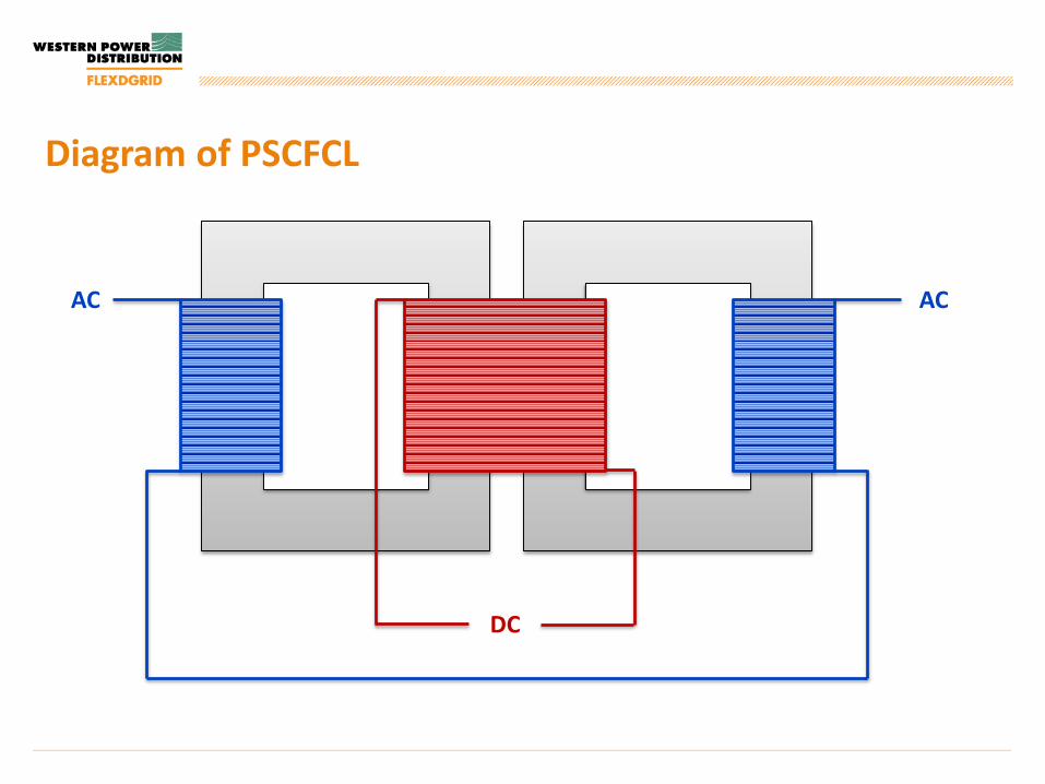
Diagram of PSCFCL
DC
AC AC

Normal Operation of PSCFCL
DC
AC AC
ɸ ɸ ɸɸ

Operation of PSCFCL during a fault
DC
ACACɸ ɸ ɸɸ

Details for GridON PSCFCL Installation
Rating: 30MVA ONAN, 38MVA ONAF Break fault level reduction required: 44% Peak fault level reduction required: 53% Mass: 168 Tonnes Dimensions (LxWxH): 6.4 x 4.5 x 5.3 m
Milestone Date
Short Circuit Tests 15th August 2014
Factory Tests Complete 6th September 2014
Device Energised 8th April 2015

Testing – GridON FCL
Tested at Ausgrid’s Testing &
Certification Lab in Sydney
FCL underwent several short
circuit tests to determine the
performance
Testing was successful with the
FCL meeting the requirements of
the contract

Testing – GridON FCL

Testing – GridON FCL
Summary of short circuit tests are shown below:
Scenario ProspectiveCurrent
RequiredLimitation
Actual Limitation
RMS Break(nom. DC Bias)
6.85kA 4.06kA 3.71kA
RMS Break(min. DC Bias)
6.85kA 4.06kA 3.75kA
Peak Make(nom. DC Bias)
20.2kA 10.16kA 10.13kA

Investigation of DC Alarm (14 July) Energisation (28 Aug) after
investigation and subsequent trip (14 Sept)
Device re-energised (17 Dec)
Operation – GridON FCL

Operation – GridON FCL
Initial alarm received for “One DC Supply Failed”, FCL switched
off for GridON investigation
Investigation found the DC supplies to be operating correctly
Other tests were taken and the decision was made to re-
energise the FCL
Device tripped “Two DC Supplies Failed” approximately 2
weeks later

Operation – GridON FCL

Operation – GridON FCL
GridON carried out a full investigation after the FCL tripped
It was found that the DC sensing circuit was capturing “0A”
even though they were supplying the minimum bias current
(130A)
The DC sensor and circuit were re-designed and the FCL was
re-energised on 17 December 2015

Learning – GridON FCLChanges in Design
The initial design from GridON agreed
during contract:
5.4x4.2x5.0m (LxWxH)
161 Tonnes
During the detailed design phase the device
footprint and weight increased to:
6.4x4.6x5.4m (LxWxH)
168 Tonnes
An extra 20% allowance had been made
during WPD design
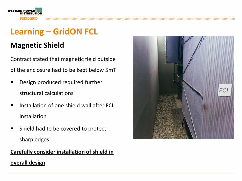
Learning – GridON FCLMagnetic Shield
Contract stated that magnetic field outside
of the enclosure had to be kept below 5mT
Design produced required further
structural calculations
Installation of one shield wall after FCL
installation
Shield had to be covered to protect
sharp edges
Carefully consider installation of shield in
overall design

Learning – GridON FCLShort circuit testing
Witnessing of short circuit testing revealed
issues with high magnetic field during
faults:
Operation of buchholz relay
Alarm from de-hydrating breather
Alarm from Calisto Gas Monitor
These issues were rectified before final
testing so that the performance onsite was
not affected
Resistive Superconducting Fault Current Limiter

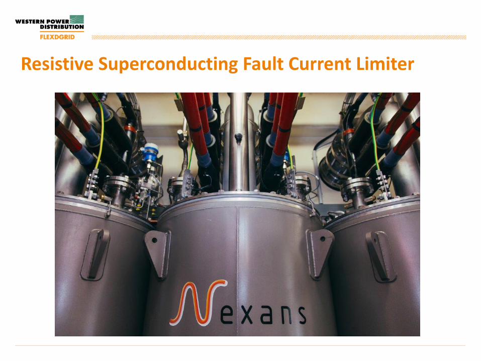
Resistive Superconducting Fault Current Limiter
Manufactured by Nexans, Germany Exploits the properties of High Temperature Superconducting
(HTS) material (Yttrium barium copper oxide)

Details for Nexans RSFCL InstallationsChester Street 132/11kV Substation: 1600A rated Peak fault reduction (@10ms) 19.76kA
to 9.90kA or below Peak fault reduction (@90ms) 7.03kA to
3.68kA or below 33.4kA short circuit current withstand
capability
Milestone DateFactory Tests Complete 23rd September 2015
KEMA Tests Complete 5th October 2015
Device Energised 25th November 2015
Milestone Date
Factory Tests Complete 30th November 2015
KEMA Tests Complete 7th December 2015
Device Energised 17th February 2016
Bournville 132/11kV Substation: 1050A rated Peak fault reduction (@10ms) 21.97kA to
7.70kA or below Peak fault reduction (@90ms) 7.66kA to
3.05kA or below 33.4kA short circuit current withstand
capability

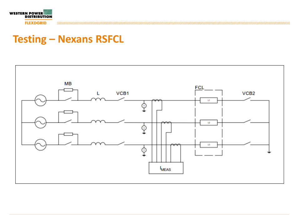
Testing – Nexans RSFCL
Tested at KEMA’s Testing Lab in
Arnhem, Netherlands
FCL underwent several short
circuit tests to determine the
performance
Testing was successful with the
FCL meeting the requirements of
the contract
Testing – Nexans RSFCL

Testing – Nexans RSFCL
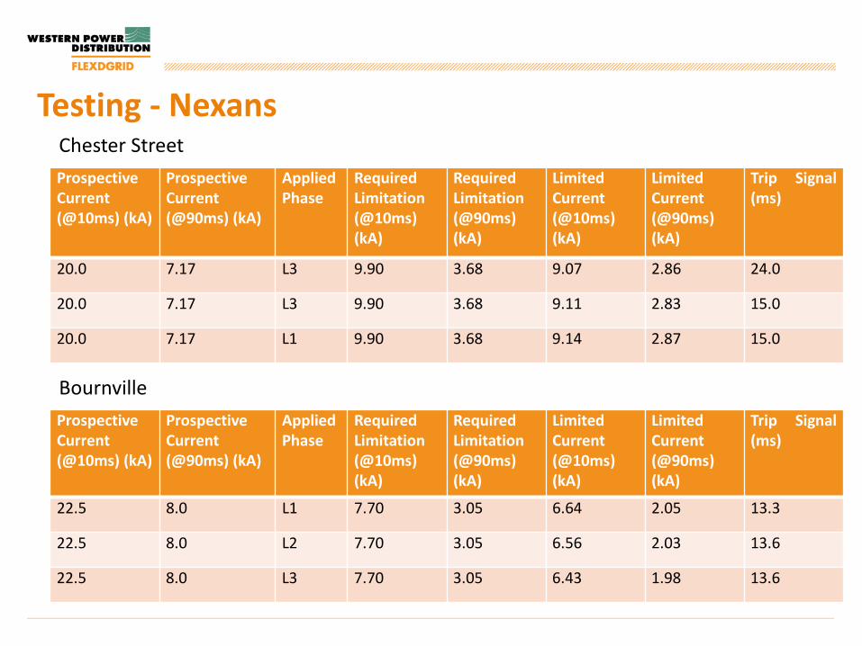
Testing - NexansChester StreetProspectiveCurrent (@10ms) (kA)
ProspectiveCurrent (@90ms) (kA)
AppliedPhase
RequiredLimitation(@10ms)(kA)
RequiredLimitation(@90ms)(kA)
LimitedCurrent(@10ms)(kA)
LimitedCurrent(@90ms)(kA)
Trip Signal(ms)
20.0 7.17 L3 9.90 3.68 9.07 2.86 24.0
20.0 7.17 L3 9.90 3.68 9.11 2.83 15.0
20.0 7.17 L1 9.90 3.68 9.14 2.87 15.0
ProspectiveCurrent (@10ms) (kA)
ProspectiveCurrent (@90ms) (kA)
AppliedPhase
RequiredLimitation(@10ms)(kA)
RequiredLimitation(@90ms)(kA)
LimitedCurrent(@10ms)(kA)
LimitedCurrent(@90ms)(kA)
Trip Signal(ms)
22.5 8.0 L1 7.70 3.05 6.64 2.05 13.3
22.5 8.0 L2 7.70 3.05 6.56 2.03 13.6
22.5 8.0 L3 7.70 3.05 6.43 1.98 13.6
Bournville

Safety Considerations Pressure relief valves:
Electromechanical Mechanical (>2.5 bar) PRD (>5bar)
Bund for safe containment of liquid nitrogen Oxygen sensor for detection of low oxygen
levels Access/Egress Policy documentation

Operation Overview
No 11kV network faults!
However, issues with the cooling systems: Chester Street FCL currently unavailable Bournville FCL currently unavailable
Manufacturer is currently working to fix cooling system issues

Learning – Issues with Cooling System Chester Street FAT (18-20th May 2015) Cooling system was unable to regulate the
temperature of the LN2 to the required set-point The temperature was rising slowly and would
have eventually led to a quench event Caused By: Higher than expected electrical losses due to
eddy currents Air leak into the cryostat vessels through safety
valve under sub-atmospheric pressure conditions
Solution: Device rating reduced - 1300A continuous
operation, 1600A for 5 hours maximum Replace 3 off safety valves with single electronic
valve with correct ratingDetailed cooling system calculations required in future with adequate margin applied.

Learning – Issues with Cooling System First time with cooling system in sustained
operation
A number of recooler faults at both Chester Street and Bournville: Damaged pipework during
commissioning Water level dropping below the trip
level. Air intake becoming clogged with
debris leading to inadequate air flow
A number of issues with the compressor components: Minor helium leak due to loose
connections Water leak at the connection Power supply failures

Learning – Issues with Cooling SystemWorks required at Chester Street to fix the cooling system issues: Recooler M9 has an undiagnosed fault
(overheating and low cooling water level). The manufacturer is organising an investigation by a specialist company
With M9 switched off the cooling capability of the device is limited. Decision taken to keep the FCL disconnected
The first scheduled maintenance for the recoolersis due in September
Works required at Bournville to fix the cooling system issues: M5 compressor unit power supply has failed and
requires replacement Investigate root cause of why compressors M3
and M6 were not operational Repair a water leak to compressor M5 Refill Nitrogen level
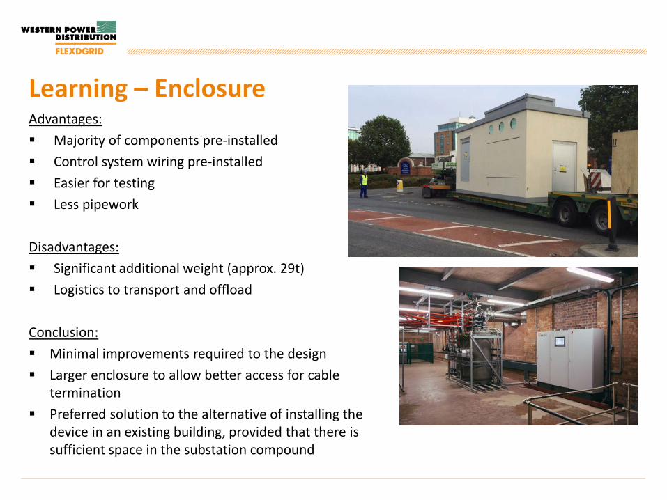
Learning – EnclosureAdvantages: Majority of components pre-installed Control system wiring pre-installed Easier for testing Less pipework
Disadvantages: Significant additional weight (approx. 29t) Logistics to transport and offload
Conclusion: Minimal improvements required to the design Larger enclosure to allow better access for cable
termination Preferred solution to the alternative of installing the
device in an existing building, provided that there is sufficient space in the substation compound

T H A N K S F O R L I S T E N I N G
Jonathan BerryWestern Power Distribution0121 6 239 459 / 07894 258 [email protected]