fault tolerance, fault diagnostics, and prognostics in ... · lockheed martin aeronautics company...
TRANSCRIPT

Lockheed Martin Aeronautics Company
Fault Tolerance, Fault Diagnostics, and Prognostics in Flight Control Systems
Dave BoddenDave BoddenSenior FellowSenior FellowLockheed Martin AeronauticsLockheed Martin Aeronautics

Background - Some LM Aeronautics Products
• F-35 Joint Strike Fighter• C-27J Spartan • C-5 Galaxy • F-16 Fighting Falcon • F-2 Defense Fighter • P-3 Orion • S-3 Viking • T-50 Golden Eagle
CC--5 Galaxy5 Galaxy
UU--2 Dragon Lady2 Dragon LadyFF--16 Fighting Falcon16 Fighting Falcon
FF--22 Raptor22 Raptor
FF--117 Nighthawk117 Nighthawk
CC--130 Hercules130 Hercules FF--35 Lightning II35 Lightning II

F35 (JSF)
• The F35 Has Unique ( and Extremely Demanding Requirements!
• Develop 3 Variants With a Common Airframe
XX--35B Short Takeoff/Vertical 35B Short Takeoff/Vertical Landing Variant (Marines)Landing Variant (Marines)
XX--35C Carrier Suitable (Navy)35C Carrier Suitable (Navy)
XX--35A Conventional (Air Force)35A Conventional (Air Force)
A Cautioner’s Tale
I’m a little High-Risk and Patience is my name.I’m really rather expert at causing pain.
I’m stealthy and deceptive and destruction is my game.You’ll know when I’ve been busy by the chaos, smoke, and flame.
In wires, pumps, and filters, actuators and in code;In sensors, chips, connectors, I oft’ make my abode.In complicated systems and even simple switches;I have so many faces – it’s hard to find the glitches.
This flying business is certainly a feat.The pilots like the challenge, they say it’s hard to beat.
The engineers are striving to mitigate the risk.By now they know my talents and the pace is pretty brisk.
I’m really an admirer of the engineering mind,But your thoroughness and detail are a stultifying grind.
I much prefer to function in a random sort of wayAnd haven’t yet decided what I’ll do today!

A Cautioner’s Tale
I quite enjoy the solitude of resting in my lair.In general, I take no umbrage when my home takes to the air.But when you turn the heat up and shake me from my bed,
You’d better be observant, be careful how you tread.
If e’er you see me working, I think you’ll be impressed;You’ll understand the value of exhaustive test.
Approach the task with vigor, intelligence and zest,For if you hope to find me you mustn’t ever rest.

A Cautioner’s Tale
Should your system-level testing turn out a trifle weak,Then rest assured the outcome would probably be bleak.
Be perceptive in your planning, let omissions be remote….
Or I’ll fool your fancy logic and calmly slit your throat!!
Author Unknown

Flight Critical Systems
• A class of system specifically designed to limit the consequence of hazards related to:− Probability-Of-Loss of Control (PLOC)
• Allocated from aircraft loss rate− Survivability
• Gunshots• Catastrophic Failures
− Aircraft Performance• Stability• Handling qualities
− Crew Safety• Structural interactions• Load limitations• Human limitations
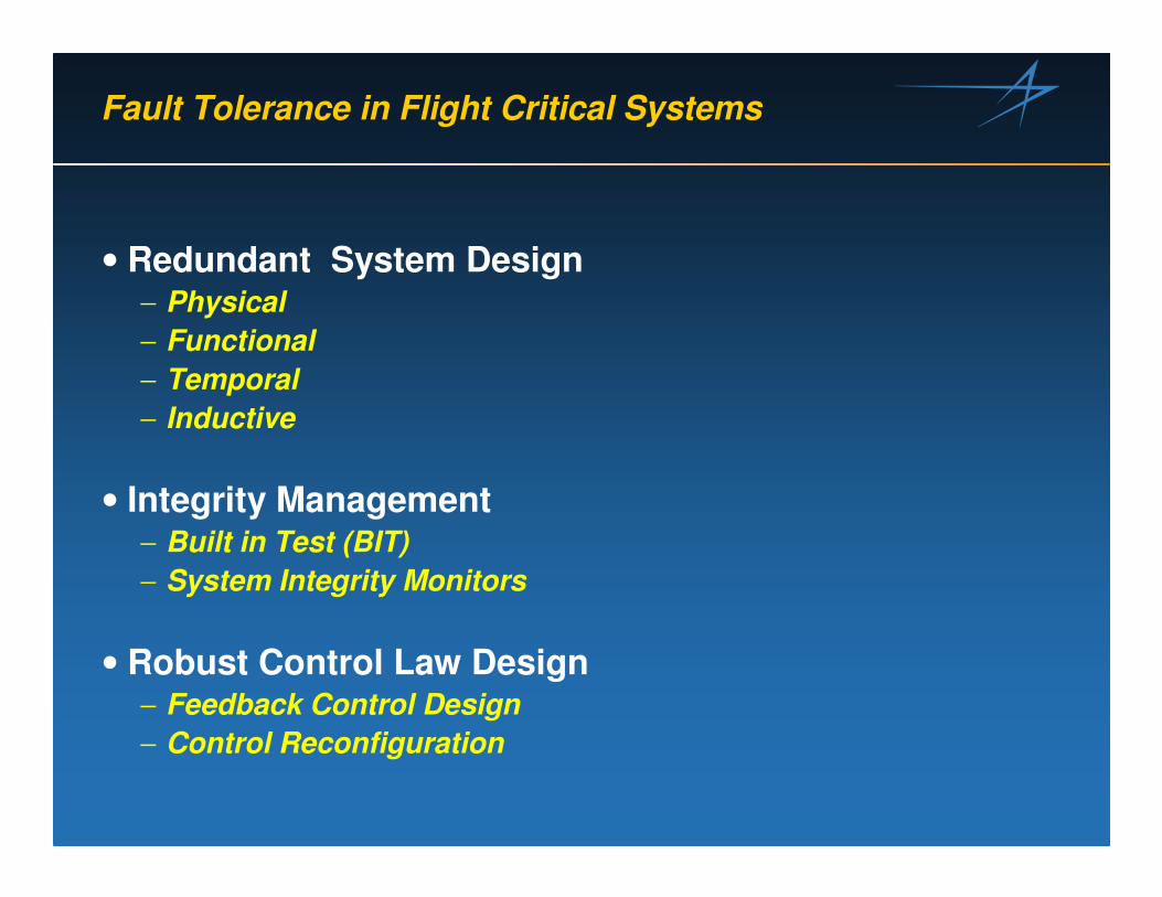
Fault Tolerance in Flight Critical Systems
• Redundant System Design− Physical− Functional− Temporal− Inductive
• Integrity Management − Built in Test (BIT)− System Integrity Monitors
• Robust Control Law Design− Feedback Control Design− Control Reconfiguration

Physical System Redundancy
• Achieved by allowing identical Processes to be Performed on Multiple Identical Physical Devices – Weight and Cost Negatives.
PNEUMATIC SENSOR ASSEMBLY
ACCELEROMETERASSEMBLY
FLIGHTCONTROLPANEL
AIR DATA PROBE DIGITAL FLIGHTCONTROL COMPUTER
RUDDER PEDALASSEMBLY
MANUALTRIM PANEL
SEAT DATARECORDER
RATE GYROASSEMBLIES
INTEGRATED SERVOACTUATORS
LEADING POWERDRIVE UNIT
TOTAL TEMPERATUREPROBE
ANGLE-OF-ATTACK TRANSMITTERS
UPGRADED CENTRAL AIR DATA COMPUTER
SIDE STICKCONTROLLER
J621J622
J624
LW
D
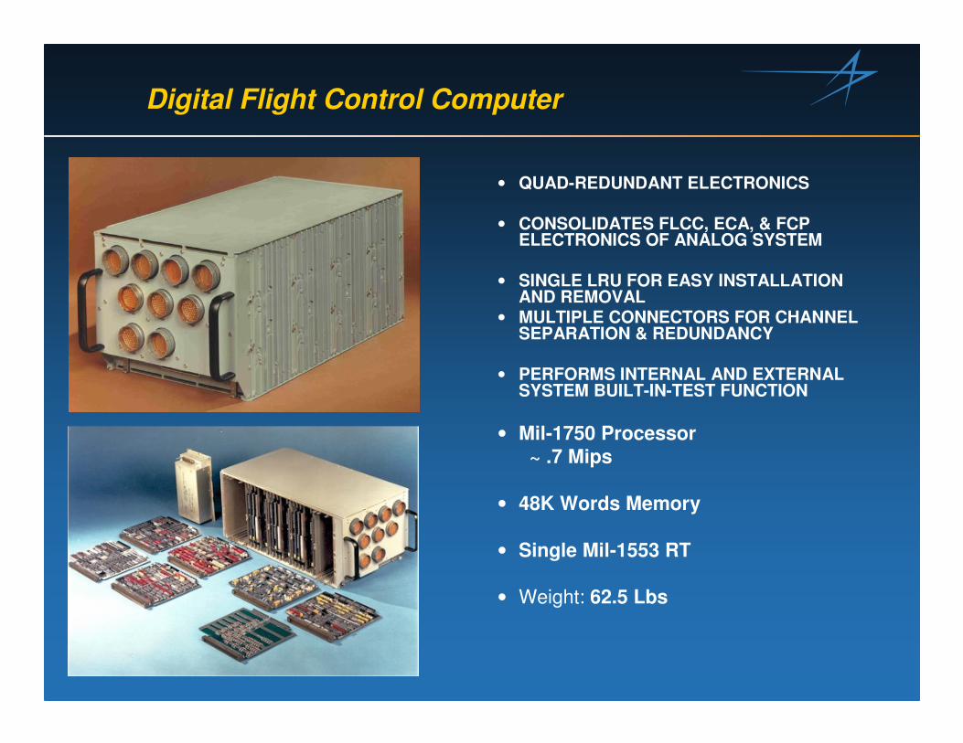
Digital Flight Control Computer
• QUAD-REDUNDANT ELECTRONICS
• CONSOLIDATES FLCC, ECA, & FCP ELECTRONICS OF ANALOG SYSTEM
• SINGLE LRU FOR EASY INSTALLATION AND REMOVAL
• MULTIPLE CONNECTORS FOR CHANNEL SEPARATION & REDUNDANCY
• PERFORMS INTERNAL AND EXTERNAL SYSTEM BUILT-IN-TEST FUNCTION
• Mil-1750 Processor~ .7 Mips
• 48K Words Memory
• Single Mil-1553 RT
• Weight: 62.5 Lbs

Rate Gyro Assemblies
• SEPARATE RATE GYRO ASSEMBLIES UTILIZED FOR PITCH, ROLL, AND YAW AXES
• QUAD-REDUNDANT− EACH ASSEMBLY CONTAINS FOUR
IDENTICAL RATE GYROS
• EACH GYRO OUTPUTS A SIGNAL CORRESPONDING TO AIRCRAFT BODY RATES DEPENDING ON INSTALLATION ORIENTATION
• EACH GYRO OUTPUTS A MONITOR SIGNAL AS A FUNCTION OF SPIN MOTOR SPEED
• EACH GYRO ACCEPTS A TORQUE SIGNAL FOR SELF-TEST CAPABILITY

Functional Redundancy
• Achieved by Allowing Identical processes to be Performed on Different Hardware− Rate Gyros, INS, EGI− Dissimilar Hardware
Typical Flight Control Grade Rate GyrosTypical Flight Control Grade Rate Gyros
RATE GYROASSEMBLIES
J621J622
J624StrapdownStrapdown Inertial Navigation SystemInertial Navigation System

Temporal Redundancy
• Achieved by Allowing Identical Processes to be performed at Different Points in Time− Commonly Used to Check Communications Data Integrity,
Communication Paths, and Insuring CPU Sanity− Watchdog Timers, Heartbeat Monitors
MUX IN
DISC S/MMODE SEL
LONG S/M
AUTOPILOT
LONG CLAWS
MIXERMUX IN
11
22
33
44
55
66
77
88
1010
1313
1414
1515
1616
00
99
1111
1212
MUX TRANSMUX FAULTMUX OUTPUTISA/CFP/LEF
L/D CLAWS
MIXER
SUPERFRAME
L/D S/M
SDR/NVM/MMOUT S/M
(ms)(ms)
CPU ACPU A IOC AIOC A
FREE RUN
(CONT)
FREE RUN
FREE RUN
FREE RUN
MUX-X STRAP
•• CPU and IOC For a Given CPU and IOC For a Given Channel Run IndependentlyChannel Run Independently
••Channels are Not Frame Channels are Not Frame SynchronizedSynchronized
F16 Flight Control System F16 Flight Control System Operates AsynchronouslyOperates Asynchronously

Inductive Redundancy
• Achieved by Cross-Correlating Different but Related Processes with One Another− Commonly Used in Estimation Techniques
FWDALTIMETER
FWD/AFTVVI & AOA
INDICATORS
Pα, Pβ,Pt(3), Ps(3)
Pt(2), Ps(2)
Pt(1), Ps(1)
AoA(3),Air Data (Triplex)
AoA
To Using Systems (i.e., HUD,DFLCC, Avionics, Engine)
SideMount Probe
Nose Probe
Left AoA Probe
PSA
CADCAFT MACH/AIRSPEEDINDICATOR
AFTALTIMETER
DIGITALFLIGHT
CONTROLCOMPUTER
AoA(2)
AoA(1)
Right AoA Probe
FWD MACH/AIRSPEEDINDICATOR
TAT
DPSENSOR
Right Static Port
Left Static Port
Alt, Baro Pot.
AoA, VVI
AOA(3) = (PAOA(3) = (Pαααααααα11--PPαααααααα22) / (K(P) / (K(PT3T3--PPββββββββ))

DC
BA
DFLCC
CONTROLLAWS
ANALOGINPUTS INTEGRATED
SERVO-ACTUATORS
DISCRETEINPUTS
LEADINGEDGEFLAP
COMMANDSERVOS
INPUTSELECTOR/MONITOR
MIDDLE VALUE/MAJORITY SELECTION
OUTPUTSELECTOR/MONITOR
PRE-SELECTEDOUTPUT
COILCURRENTMONITOR
DFLCCELECTRICALHARDWARE
ISAHYD
HARDWARE
HORIZONTALTAILS (2)
FLAPERONS (2)
RUDDER
LEF
Redundancy Implementation – F16

Input Selector Monitor
S
MONITOR/LOGIC TRIP LEVEL
BRANCH A INPUT
FAULT PROCESSING
MID-VALUE
BRANCH A
S
MONITOR/LOGIC TRIP LEVEL
BRANCH B INPUT
FAULT PROCESSING
MID-VALUE
BRANCH B
S
MONITOR/LOGIC TRIP LEVEL
BRANCH C INPUT
FAULT PROCESSING
MID-VALUE
BRANCH C
S
MONITOR/LOGIC TRIP LEVEL
BRANCH D INPUT
DIGITAL FLIGHT CONTROL COMPUTER
FAULT PROCESSING
MID-VALUE
BRANCH D

Mid - Value Select
Consider the Following Values for AOAConsider the Following Values for AOA
A = 10.3A = 10.3oo
B = 10.1B = 10.1oo
C = 10.2C = 10.2oo
Average Value = 10.2Average Value = 10.2oo
MidMid--Value = 10.2Value = 10.2oo
After a Failure in Branch B, Consider the Following Values for AAfter a Failure in Branch B, Consider the Following Values for AOAOA
A = 10.3A = 10.3oo
B = 56.0B = 56.0oo
C = 10.2C = 10.2oo
Average Value = 25.5Average Value = 25.5oo
MidMid--Value = 10.3Value = 10.3oo
A Mid A Mid –– Value Select Minimizes Errors Associated with Failures Until Value Select Minimizes Errors Associated with Failures Until the Device is Declared Failed (Exceeds Persistence Count)the Device is Declared Failed (Exceeds Persistence Count)

Diagnostics and Integrity Management

System Integrity Management Applies The Idea of “Verticality of Testing”
The Elimination of Latent FailuresIs The Object of all Ground Test Functions
Each Succeeding Level of Test Limits The Exposure of The System To Hazards
Tolerances and CoveragesAre Most Stringent
Widest Tolerance, Lowest Coverage
Tolerances and CoveragesAre Most Stringent
� Equipment Qualification (ATPs)
� Pre-Flight BIT
� In-Flight Monitoring
� Post-Flight BIT
� Maintenance BIT
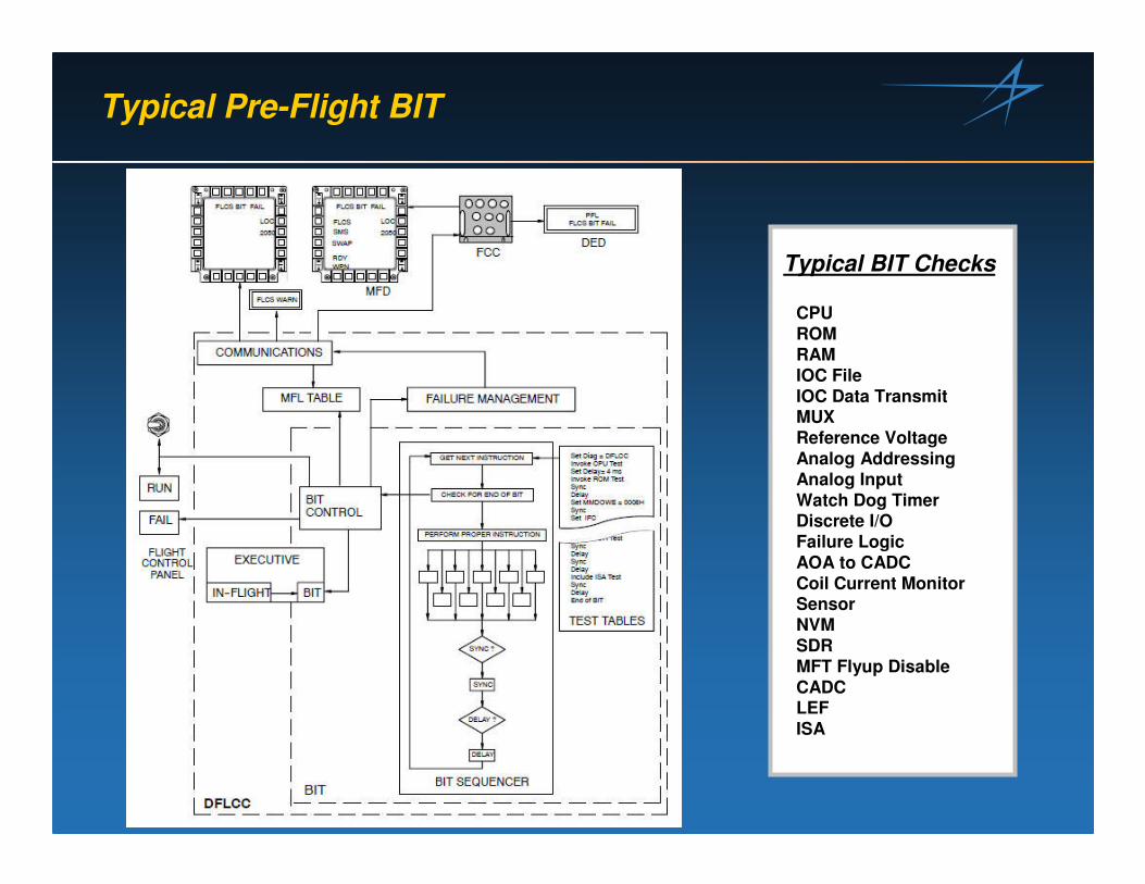
Typical Pre-Flight BIT
CPUROMRAMIOC FileIOC Data TransmitMUXReference VoltageAnalog AddressingAnalog InputWatch Dog TimerDiscrete I/OFailure LogicAOA to CADCCoil Current MonitorSensorNVMSDRMFT Flyup Disable CADCLEFISA
Typical BIT Checks

Input Selector Monitor
S
MONITOR/LOGIC TRIP LEVEL
BRANCH A INPUT
FAULT PROCESSING
MID-VALUE
BRANCH A
S
MONITOR/LOGIC TRIP LEVEL
BRANCH B INPUT
FAULT PROCESSING
MID-VALUE
BRANCH B
S
MONITOR/LOGIC TRIP LEVEL
BRANCH C INPUT
FAULT PROCESSING
MID-VALUE
BRANCH C
S
MONITOR/LOGIC TRIP LEVEL
BRANCH D INPUT
DIGITAL FLIGHT CONTROL COMPUTER
FAULT PROCESSING
MID-VALUE
BRANCH D

Typical Input Monitor Trip Levels
AOA = - With the gear handle down and in-flight, Threshold = 6o
- Else threshold equals the Max Value of 6o, (–0.1333*QCSEL+48.67)
= Threshold increases above 6o when Qc < 300KCAS
Example: 170KCAS = 100psf
-0.1333 x 100psf = -13.33
-13.3 + 48.67 = 35.37o
FPSTK = 5 lbs 7 Frames
FRSTK = 3 lbs 7 Frames
FRUD = 15 lbs 7 Frames
NACL = .9g 7 Frames
LACL = .225g 7 Frames

Input Monitor Flow Diagram for Quad Devices
Mid Value SelectMid Value Select
Fault IdentificationFault Identification
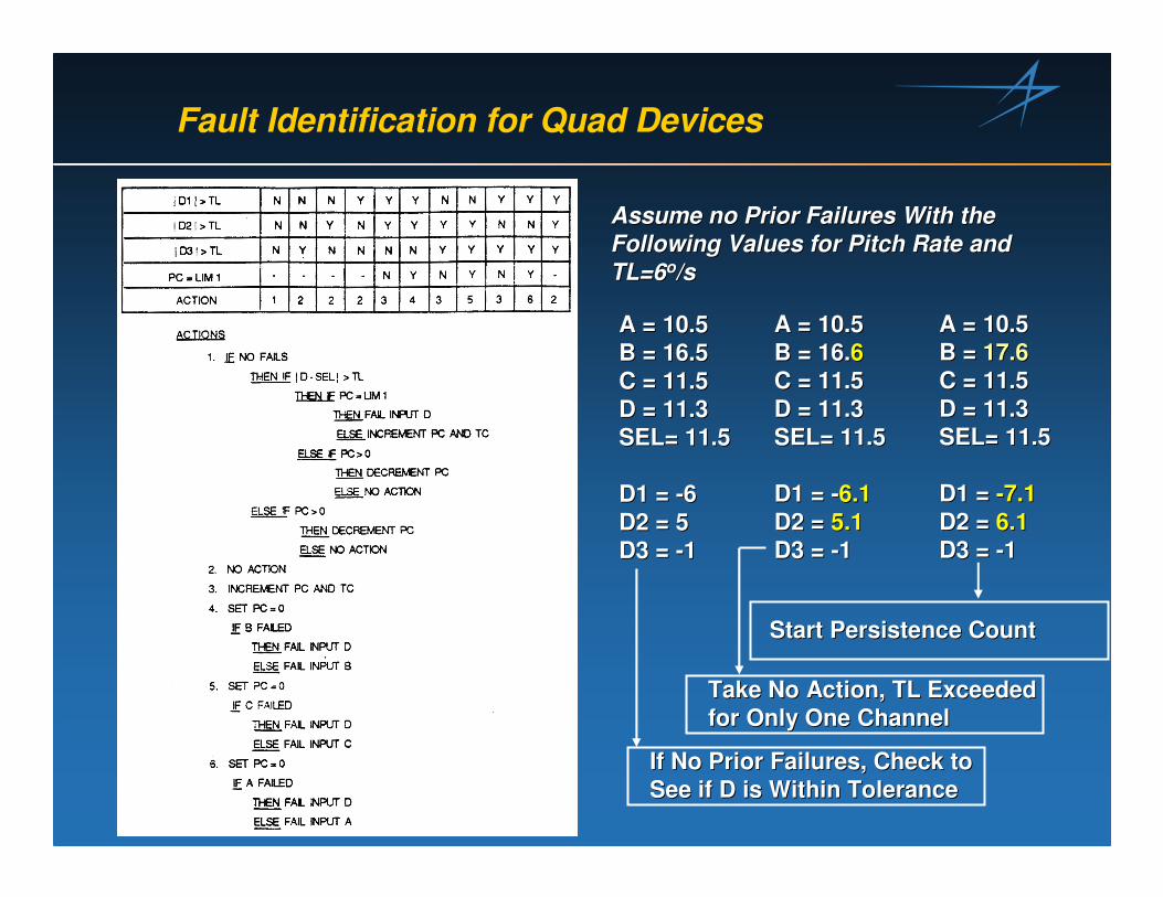
Fault Identification for Quad Devices
Assume no Prior Failures With the Assume no Prior Failures With the Following Values for Pitch Rate and Following Values for Pitch Rate and TL=6TL=6oo/s/s
A = 10.5A = 10.5B = 16.5B = 16.5C = 11.5C = 11.5D = 11.3D = 11.3SEL= 11.5SEL= 11.5
D1 = D1 = --66D2 = 5D2 = 5D3 = D3 = --11
A = 10.5A = 10.5B = 16.B = 16.66C = 11.5C = 11.5D = 11.3D = 11.3SEL= 11.5 SEL= 11.5
D1 = D1 = --6.16.1D2 = D2 = 5.15.1D3 = D3 = --11
A = 10.5A = 10.5B = B = 17.617.6C = 11.5C = 11.5D = 11.3D = 11.3SEL= 11.5 SEL= 11.5
D1 = D1 = --7.17.1D2 = D2 = 6.16.1D3 = D3 = --11
If No Prior Failures, Check to If No Prior Failures, Check to See if D is Within ToleranceSee if D is Within Tolerance
Take No Action, TL Exceeded Take No Action, TL Exceeded for Only One Channelfor Only One Channel
Start Persistence CountStart Persistence Count

Robust Control Algorithms
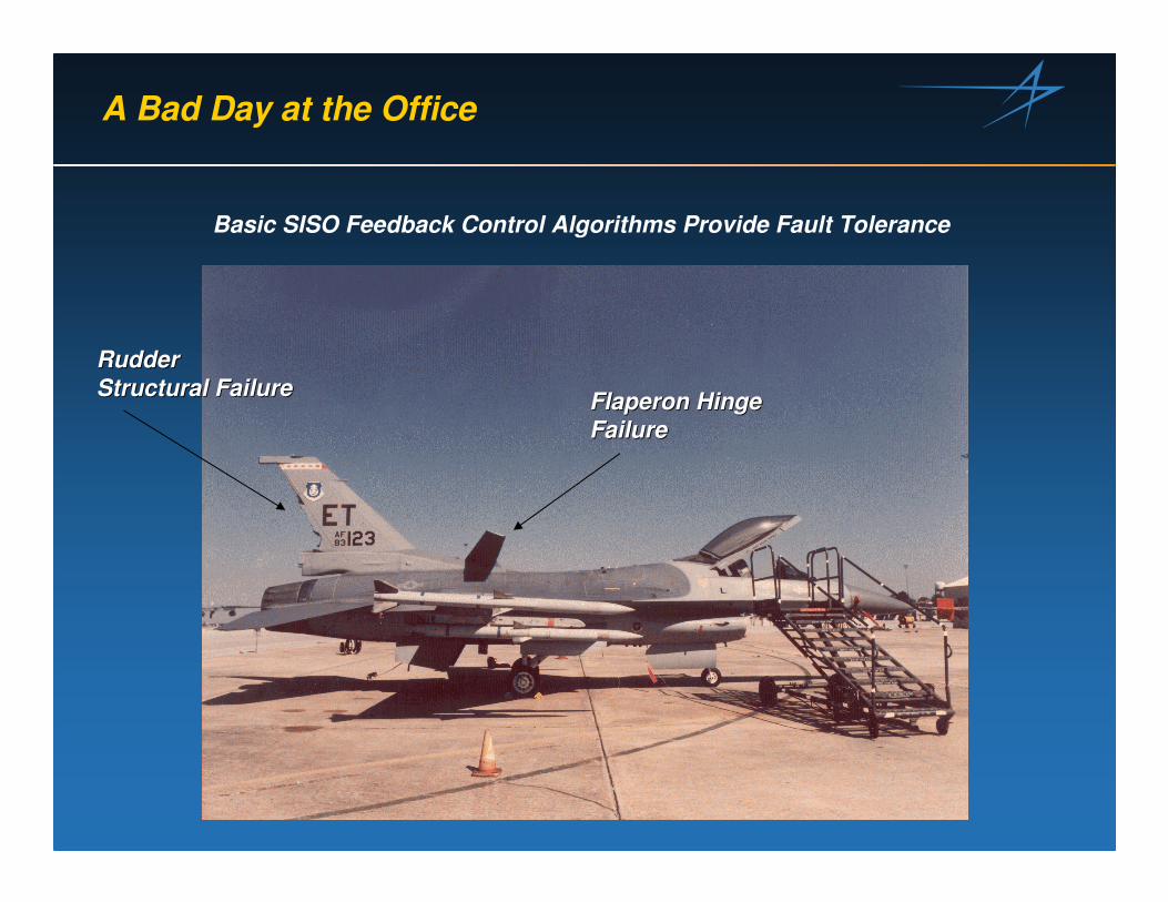
A Bad Day at the Office
Basic SISO Feedback Control Algorithms Provide Fault Tolerance
Rudder Rudder Structural FailureStructural Failure FlaperonFlaperon Hinge Hinge
FailureFailure

A Bad Day at the Office - Continued
•• Control Reconfiguration Buys you Better Handling Qualities withControl Reconfiguration Buys you Better Handling Qualities with FailuresFailures•• Adaptive Control Allows for Better Control Reconfiguration witAdaptive Control Allows for Better Control Reconfiguration withhFailures Undetectable by System Monitors, BIT, etc.Failures Undetectable by System Monitors, BIT, etc.

A New Concept in Inductive Redundancy
Synthetic Redundancy via Prognostics

Synthetic Redundancy via Prognostics
• “PHM as a Design Variable in Air Vehicle Conceptual Design”, Bodden, D.S., et al., AIAA Journal of Aircraft, Vol 43, Number 4, Pages 1053-1058
• "Seeded Failure Testing and Analysis of an Electro-Mechanical Actuator", Bodden, D.S., and Clements, N.S., Proceedings of the IEEE Aerospace Conference, March 2007, Big Sky Montana
• "Seeded Fault Testing and In-situ Analysis of Critical Electronic Components in EMA Power Circuitry", Baybutt, M., Bodden, D.S., et.al., Proceedings of the IEEE Aerospace Conference, March 2008, Big Sky Montana.
• Prognostics Refers to the Future State of Reliability of a Component, Device, Subsysem, etc.
• The Current State-of-the-Art for Prognostics and Health Management (PHM) is centered on Condition Based Maintenance (CBM); i.e. performing Maintenance or Replacing Components as Required Rather than Scheduled.

Hypothesis 1
Accurate and Correct Implementation of Accurate and Correct Implementation of Prognostics Technology Should Result in an Prognostics Technology Should Result in an Operational Reliability close to 1 for a Particular Operational Reliability close to 1 for a Particular System, SubSystem, Sub--system, or Componentsystem, or Component
� Realistic?� Cost of Prognostics?�Mechanical Systems?�Electrical Systems?�Eliminate Physical Redundancy?
PNEUMATIC SENSOR ASSEMBLY
ACCELEROMETERASSEMBLY
FLIGHTCONTROLPANEL
AIR DATA PROBE DIGITAL FLIGHTCONTROL COMPUTER
RUDDER PEDALASSEMBLY
MANUALTRIM PANEL
SEAT DATARECORDER
RATE GYROASSEMBLIES
INTEGRATED SERVOACTUATORS
LEADING POWERDRIVE UNIT
TOTAL TEMPERATUREPROBE
ANGLE-OF-ATTACK TRANSMITTERS
UPGRADED CENTRAL AIR DATA COMPUTER
SIDE STICKCONTROLLER
J621J622
J62 4
LW
D

Hypothesis 2
Optimization of the Air Vehicle Configuration for Optimization of the Air Vehicle Configuration for Reliability Facilitates An Optimal Reliability Facilitates An Optimal System/Subsystem Design System/Subsystem Design
� Objective
Optimize Number of Control Surfaces and Actuator Redundancywith Prognostics as a Design Variable
Which has Better Mission Reliabilty?
Failure Immunity?

Air Vehicle Conceptual Design Process
� Optimized for Performance� “Modified” for Stability & Control, etc.� Reliability in Subsystems as Required Through Redundancy and Reliable Components
Optimize Primary Control Optimize Primary Control Physical Redundancy Physical Redundancy ParametersParameters•• Number Control SurfacesNumber Control Surfaces•• Actuator RedundancyActuator Redundancy
Technology Set
Reference Mission
Integrated SynthesisAnalysis
Cost / Benefit Studies
Synthesis Parametric Analysis
Design Data Package
Geometry Mass Properties Aerodynamics
Propulsion Performance
Optimization with PHM as a Design Variable
WeightReference Baseline
Iteration ConventionalPHM
ReliabilityAvailability
Savings
LCC
Technology Set
Technology Set
Reference Mission
Integrated SynthesisAnalysis
Cost / Benefit Studies
Synthesis Parametric Analysis
Design Data Package
Geometry Mass Properties Aerodynamics
Propulsion Performance
Optimization with PHM as a Design Variable
WeightReference Baseline
Iteration ConventionalPHM
ReliabilityAvailability
Savings
LCC

Sea Based Endurance (SBE) UAV Selected for Optimization Studies
Wing Span 66.56 FtWing Area 560 Sq. FtOverall Length 37.00 FtEmpty Weight (w/ 6% margin) 12,716 lbsInternal Payload Weight 2,000+ lbsInternal Fuel Weight (JP-5) 12,980 lbTakeoff Gross Weight Class 28,000 lbTime-On-Station @ 600 nm 10.0 Hr GoalTotal Mission Time 13.5 Hr GoalCruise Speed 0.65 MLoiter Speed 0.35 MMax Speed 0.75 M
Specifications
Carrier Suitable:• Catapult Launch• Arrested Recovery• 1.02 Spot Factor (F/A-18C Ref)
Single, Turbofan Engine:• 9,000 lb Thrust Class(PW800 or Honeywell AS907L)
Configuration SBE-C07 Shown

Electro Hydrostatic Actuators
Control Electronics (CE) NDB
IEEE 1394 High Speed
Serial Interface
Digital Signal Processor (DSP)
Sol. Drives & Input
Conditioning
Pow er Drive Electronics
(PDE)
XMIT RCV CCDL
Port 1
Port 3
Port 2
28 VDC
Firewire Interface
270 VDC
EHA
Resolv
#1 Fail Safe Sol
Sol Drv , Exc.
Model Channels
Pressure & Temp Sensors
#2 #3
C H
A
C H
B
C H
C
LVDT Electronics Unit
Model Channels
M
Control Electronics (CE) NDB
IEEE 1394 High Speed
Serial Interface
High Performance Digital Signal
Processor (DSP)
Power Drive Electronics
(PDE)
XMIT RCV CCDL
Port 1
Port 3
Port 2
28 VDC
Firewire Interface
270 VDC
EHA Resolv
#1 Blocking Sol
Sol Drv , Exc.
Pressure & Temp Sensors
Pressure & Temp Sensors
#2 #3
C H
A
Bypass Sol
LVDT
Resolv
Control Electronics (CE) NDB
IEEE 1394 High Speed
Serial Interface
Power Drive Electronics
(PDE)
XMIT RCV CCDL
Port 1
Port 3
Port 2
28 VDC
Firewire Interface
270 VDC
Sol Drv , Exc.
Electronics Unit
C H
A
C H
B
C H
C
C H
B
Model Channel
High Performance Digital Signal
Processor (DSP)
C H
C
M
M
Sol. Drives & Input
Conditioning
Sol. Drives & Input
Conditioning
Bypass Sol
Model Channel

Optimization Space
Flap
Rudder
Inbd FlapOutbd Flap
Inbd Rudder
Outbd Rudder
jj Airframe Configuration1. 1. Nominal*Nominal*2. 2. Split FlapsSplit Flaps3. 3. Split RuddersSplit Rudders4. 4. Split Flaps & RuddersSplit Flaps & Rudders
kk Actuator Configuration1.1. Simplex Actuators/Simplex Actuators/
Simplex ElectronicsSimplex Electronics2.2. Duplex ActuatorsDuplex Actuators3.3. Simplex Flap/Simplex Flap/
Duplex RudderDuplex Rudder4.4. Simplex/Simplex/
Duplex ElectronicsDuplex Electronics
mm PHM Configuration1.1. no PHMno PHM2.2. With EHA PHM 85%With EHA PHM 85%3.3. With EHA PHM 60%With EHA PHM 60%4.4. With EHA PHM 35%With EHA PHM 35%5.5. No PHM with TCINo PHM with TCI
nn Failure State1.1. no Failuresno Failures2.2. Left RudderLeft Rudder3.3. Left FlapLeft Flap4.4. InbdInbd FlapFlap5.5. OutbdOutbd FlapFlap6.6. InbdInbd RudderRudder7.7. OutbdOutbd RudderRudder8.8. Left Rudder 2Left Rudder 2ndnd FailFail9.9. Left Flap 2Left Flap 2ndnd FailFail
10.10. Left Flap/Right RudderLeft Flap/Right Rudder11.11. InbdInbd Rudder/Rudder/InbdInbd FlapFlap12.12. InbdInbd Rudder/Rudder/OutbdOutbd FlapFlap13.13. OutbdOutbd Rudder/Rudder/InbdInbd FlapFlap14.14. OutbdOutbd Rudder/Rudder/OutbdOutbd FlapFlap15.15. Left Left InbdInbd Rudder/Left Rudder/Left OutbdOutbd RudderRudder16.16. Left Left InbdInbd Flap/Left Flap/Left OutbdOutbd FlapFlap17.17. Right Right InbdInbd Rudder/Left FlapRudder/Left Flap
*Nominal Configuration*Nominal Configuration-- No Split SurfacesNo Split Surfaces-- k=2, m=1, n=1k=2, m=1, n=1

Reliability Criteria
√ Failure Immunity- Addresses Consequences of Failure of any Component- Based on Fault Tree Analysis and Adjusted Supplier MTBF Data
√ Probability of Loss of Aircraft (PLOA) or Mission Reliability ( In the Context of this Application)- Overall Roll Up of Reliability Allocations- Estimate of Number of Aircraft Lost per xx Flt Hrs or Missions- Based on Fault Tree Analysis and Adjusted Supplier MTBF Data
√ Mission Availability- Measure of Percentage of Time Aircraft Would be Available- Based on Adjusted Supplier MTBF Data and Time To Repair an LRU
Several Criteria Evaluated as Reliability Constraints for Optimizing the Air Vehicle Configuration

Optimization Problem
• Carrier Landing Dispersion-60<x<20-10<y<10
• Mission Reliability (Flt Control Actuator PLOA Allocation)< .13 Crashes per 10000 Flights< .43 Crashes per 10000 Flights (13.5 Hour Flight)
• Mission Availability> 99%
XX
YY
Optimize the Air Vehicle Design to Minimize the Air Vehicle Weight and Life Cycle Cost, Subject to the Following Constraints:
Optimization Parameters are: j, k, m

CASE Mission Reliability Constraint PHM ∆ ∆ ∆ ∆ Weight* ∆ ∆ ∆ ∆ LCC* Optimal (Failures/10000 Missions) Effectivity (lbs) ($M) Configuration
0.13 0.43 Required j k m
1. No PHM^ X - -45 -11.7 3 4 12. No PHM - TCI^ X - -45 21.6 3 4 53. EHA PHM^ X 35% -45 -11.8 3 4 44. EHA/EU PHM X 60% -101 -35.7 1 3 35. No PHM^ X - -45 -11.7 3 4 16. No PHM - TCI X - -101 -14.6 1 3 57. EHA PHM X 35% -101 -33.1 1 3 48. EHA/EU PHM X 35% -101 -32.7 1 3 4
Optimization Results
Configuration j=3, k=4 Configuration j=1, k=3
Simplex EHA, Duplex EU Simplex EHADuplex EHA
* Relative to Baseline Configuration ^ Did not Meet Mission Availability Constraint