fcd vbenim0002-00 a4 – 09/16 maintenance - flowserve · slab gate valve m34 fcd vbenim0002-00 a4...
TRANSCRIPT

1
FCD VBENIM0002-00 A4 09/16 FCD VBENIM0002-00 A4 09/16
Experience In Motion
Installation Operation
Maintenance
USER INSTRUCTIONSSlab Gate Valve M34FCD VBENIM0002-00 A4 – 09/16

2
FCD VBENIM0002-00 A4 09/16
flowserve.com
CONTENTSSections
1 Scope ............................................................................................................................................. 4
2 Safety ............................................................................................................................................. 4
3 Namplate information ..................................................................................................................... 5
4 Slab gate cross sectional drawing and components ....................................................................... 6
5 Storage ........................................................................................................................................... 7
6 Lifting and handling ........................................................................................................................ 7
7 Installation ...................................................................................................................................... 9
7.1 General information .................................................................................................................. 9
7.2 Standard stem/flowline valve orientation .................................................................................. 10
8 Valve working condition.................................................................................................................. 11
8.1 Operating instructions .............................................................................................................. 11
8.2 Isolation slab gate valve features .............................................................................................. 12
9. Valve leakage .................................................................................................................................. 13
10 Venting/bleeding of the valve body cavity ....................................................................................... 13
11 Maintenance ................................................................................................................................... 14
11.1 Disassembly tools ..................................................................................................................... 14
11.2 Disassembly ............................................................................................................................. 15
11.3 Inspection and maintenance ..................................................................................................... 24
12 Reassembly .................................................................................................................................... 24
13 Recommended assembly lubricants ............................................................................................... 25
14 Minor repairs .................................................................................................................................. 25
15 Preventive maintenance schedule ................................................................................................... 25
15.1 Lubrication / sealing on stem area ............................................................................................ 25
16. Bolting ............................................................................................................................................ 26
16.1 Recommendation ...................................................................................................................... 26
16.2 Bolt tightening sequence ........................................................................................................... 26
16.3 Bolt tightening torque values .................................................................................................... 26
16.3.1 Un/Unc Bolt Tightening Torque Table .................................................................................... 26
16.3.2 Capscrew tightening torque table .......................................................................................... 27
17 Recommended valve inspection and maintenance ......................................................................... 30
17.1 Preventive actions ..................................................................................................................... 30
17.2 Valve testing and inspection ..................................................................................................... 30

3
FCD VBENIM0002-00 A4 09/16 FCD VBENIM0002-00 A4 09/16
Figures
Figure 1 - API 6D Marking ................................................................................................................................ 4
Figure 2 - Slab gate valve vertical lifting (A) and suitable lifting equipment (B) ............................................... 6
Figure 3 - Slab gate valve horizontal lifting ...................................................................................................... 7
Figure 4 - Slab gate valve horizontal lifting for size above 24” included .......................................................... 7
Figure 5 - Valve orientations ............................................................................................................................ 9
Figure 6 - Bleeder detail ................................................................................................................................... 15
Figure 7 - Operator removal sequence ............................................................................................................. 16
Figure 8 - Yoke bolting removal ....................................................................................................................... 16
Figure 9 - Yoke disassembly and stem fire safe gasket and bearing removal. .................................................. 17
Figure 10 - Bonnet disassembly ....................................................................................................................... 18
Figure 11 - Slab gate disassembly according to steps n° 12, 13 and 14. ......................................................... 18
Figure 12 - Stem head disengaging. ................................................................................................................. 19
Figure 13 - Gate guides removal ...................................................................................................................... 20
Figure 14 - Seat spreader tools use. ................................................................................................................ 20
Figure 15 - Slab gate removal. ......................................................................................................................... 21
Figure 16 - Seat lifter tool installation and use ................................................................................................. 21
Figure 17 - Seat disassembly from the body .................................................................................................... 22
Figure 18 - Seat gaskets and springs stripping. ............................................................................................... 22
Figure 19 - Short side numbering sequence. DO NOT CONSIDER bolting on long side. .................................. 25
Figure 20 - Long side numbering sequence. DO NOT CONSIDER bolting on short side. ................................. 26

4
FCD VBENIM0002-00 A4 09/16
flowserve.com
1 SCOPE This manual is applicable to SLAB GATE VALVE and its purpose is to give guidance to the user with regard to the storage,
handling, installation and maintenance.
2. SAFETY Terms concerning safety The safety terms DANGER, WARNING, CAUTION and NOTE are used in these instructions to highlight particular dangers
and/or to provide additional information on aspects that may not be readily apparent.
WARNING: Slab gate valves are pressure vessels designed and rated for specific application conditions. Before installation, check the serial number and / or the tag number to ensure that the valve and actuator being installed are correct for the intended application.
DANGER: Do not use the valve outside of its rated design limits. Exceeding the design limits may cause hazardous conditions including leakage of the process media or rupture of the pressure boundary resulting in possible process loss, equipment or environmental damage, or serious personal injury or death.
SAFETY directions must be strictly followed.
STOP!
Symbol DescriptionDANGER: indicates that death, severe personal injury and/or substantial property damage will occur if proper precautions are not taken.
WARNING: indicates that death, severe personal injury and/or substantial property damage can occur if proper precautions are not taken.
CAUTION: indicates that minor personal injury and/or property damage can occur if proper pre-cautions are not taken.
NOTE: indicates and provides additional technical information, which may not be very obvious even to qualified personnel.Compliance with other, not particularly emphasised notes, with regard to transport, assembly, operation and maintenance and with regard to technical documentation (e.g. in the operating instruction, product documentation or on the product itself) is essential, in order to avoid faults, which in themselves might directly or indirectly cause severe personal injury or property damage
Table 1 Definition of safety symbols and markings
STOP!

5
FCD VBENIM0002-00 A4 09/16 FCD VBENIM0002-00 A4 09/16
3. NAMPLATE INFORMATION The Flowserve slab gate valve nameplate (Figure 1) is located on the valve body ribs upper surface. For valves without ribs, the name-
plate is located on bonnet side.
The information provided are hereafter summarized.
Please reference the serial number when contacting Flowserve in regards to your valve in order to expedite any request and ensure
that correct information are given.
Key:
(A) API marking (if applicable)
(1) Nominal pipe size (R = reduced bore)
(2) Pressure class
(3) Valve model number (figure number)
(4) Valve assembly serial number
(5) Maximum operating pressure at minimum operating temperature [bar]
(6) Minimum operating temperature [°C]
(7) Maximum operating pressure at maximum operating temperature [bar]
(8) Maximum operating temperature [°C]
(9) Body material
(10) End connection material
(11) Slab material
(12) Seat material
(13) Stem material
(14) Seals material
(15) Fire safe standard
(16) Face-to Face / End-to-End (if applicable)
(17) Month and year of manufacture
(18) Seat feature
(19) Quality Specification Level
(20) TAG number
Figure 1 - API 6D Marking

6
FCD VBENIM0002-00 A4 09/16
flowserve.com
4. SLAB GATE CROSS SECTIONAL DRAWING AND COMPONENTS

7
FCD VBENIM0002-00 A4 09/16 FCD VBENIM0002-00 A4 09/16
4. SLAB GATE CROSS SECTIONAL DRAWING AND COMPONENTS
5. STORAGE The type of packaging must be defined by the customer’s order and shall be appropriate to ensure safe transportation to the final
destination and possible conservation before installation.
The valves have to be stored in a closed, cleaned and dry place, protected from bad weather and corrosive atmosphere.
Make sure that the end sealing surfaces and/or B.W. ends have been coated with corrosion protection painting and correctly closed by means of wooden or rubber discs.
Periodical checks have to be carried out in the dedicated storage area to verify that the integrity of packaging is maintained.
CAUTION:
• Storage in an open area for a limited period can be considered only in case the valves have appropriate packaging [packed in cases for sea transportation and goods well protected with barrier sacks].• Do not place the packages directly on the ground.• Do not expose the packages to the weather or directly to the sun.• Verify the packaging every two months.
6. LIFTING AND HANDLING The valve shall be lifted in vertical position as shown in the below Figure 2 by means of soft sling or lifting chain with adequate
SWL (Safety Working Load).
Warning: Valve vertical lifting shall be done using all 4 welded eyebolts.
The valve bonnet flange has 4 welded lifting points suitable to be hooked by (Figure 2):
• Shackles
• Eyehook with latch
Figure 2 Slab gate valve vertical lifting (A) and suitable lifting equipment (B)
AB
Soft slings orlifting chain
STOP!

8
FCD VBENIM0002-00 A4 09/16
flowserve.com
ONLY bare stem / gear operated valve can be horizontally lifted according to Figure 3 and procedure, for actuated valve horizontal lifting is only allowed if it has been defined in the purchase order.
Figure 3 - Slab gate valve horizontal lifting
Figure 4 - Slab gate valve horizontal lifting for size above 24” included

9
FCD VBENIM0002-00 A4 09/16 FCD VBENIM0002-00 A4 09/16
7. INSTALLATION7.1. GENERAL INFORMATION Remove the valve from crate or case by means of lifting lugs being careful not to damage the valve ends and not scratch the paint.
Remove the protection discs and the corrosion protection coating from the ends.
Make sure that the relevant surfaces are not damaged and there are no loose parts.
Before installation, fix the gear or the actuator to the valve yoke (Pos.7) top (if shipped separately take care to not put grease between valve mounting flange and gear or actuator mounting flange), tighten the operator bolting in accordance with the operator IOM bolt tightening torque table, set the open and close position or verify the operator set-up in case the actuator has been fixed on the top of the valve by factory.
Remove any foreign object from the valve bore.
Make sure that the valve is correctly placed and aligned with the pipeline.
For bolted end valves be careful to use adequate gaskets and bolting. Tighten the bolts gradually, in cross position with the proper loads recommended by the gasket supplier or end user recommended practice.
CAUTION: It is strongly recommended to perform piping flushing before installation of the valve; if this is not possible, the valve must be set with the gate in full open position before starting the flushing.
For welded end valves use an adequate welding procedure which shall limit the temperature to maximum 100 °C at 100 mm of distance from the seat ring rear face. The use of transition pup is mandatory when this condition is not possible.
In case of welding to higher strength pipe the thickness of the component shall at least equal to the ratio of minimum specified yield strength of the pipe to minimum specified yield strength of the component. The maximum thickness of the component shall not exceed 1.5 times the pipe thickness. The use of transition pup is mandatory when the above condition cannot be achievable.
To avoid bending stresses the valve and the line piping have to be correctly supported.
Unless specifically requested the valves are not designed for supporting external loads (e.g. seismic loads).
In order to check the integrity of valve components and avoid damages due to wear we suggest regular ‘in service maintenance opera-tions’ at least once per year (more than once a year in case of severe use e.g. dirty service) or whenever requested by local regulations.
The limits of temperature and pressure are clearly indicated on the name plate, Flowserve declines any responsibility for any use outside the above limits.
Flowserve declines any responsibility should the valve not be used for the service indicated on the client’s data sheets.
The user is not allowed, in any case, to modify the valve; this action causes immediate expiring of guarantee period and API marking.
Flowserve refuses any liability for any damage to personnel, property or plants caused by incorrect usage of valves, incorrect or maintenance not strictly carried out in line with these procedures, unskilled personnel or non-observance of safety rules.
In case Flowserve is not aware of the final use of the valve (e.g. valve ordered and stocked by a third party) it is the responsibility of the third party or of the user to verify the suitability of the valve material combination for the medium and/or service the valve is to be used.
Unless specifically requested the valves are furnished without thermal and noise insulation.
Even if the valves are provided with an antistatic device it is strongly recommended to ground the line.
Plant operating personnel must be equipped with the proper safety equipment (e.g. glass, gloves, reinforced boot, hear plugs) according to local regulation.
WARNING:
• Carefully verify that the direction of the flow in the line corresponds to the arrow indicated on the valve body. Valves without arrow are bi-directional.
• Carefully verify the assembly of the overpressure relief device if any.• Carefully see the actuator user manual for the actuator preparation.
STOP!

10
FCD VBENIM0002-00 A4 09/16
flowserve.com
7.2. STANDARD STEM/FLOWLINE VALVE ORIENTATION• For manual valves any stem orientation with the stem over the horizontal plane is allowed: at limit the stem can be
found in hori zontal position (see figure).• For motor operated valves the vertical stem position is the only allowed. Any other option must be defined in the
purchase order.
Figure 5 - Valve orientations
PERMITTED ONLY FORMANUAL VALVES
PERMITTED ONLY FORMANUAL VALVES
NOT RECOMMENDED
RECOMMENDED
PERMITTED ONLY FORMANUAL VALVES
PERMITTED ONLY FORMANUAL VALVES
NOT RECOMMENDED
RECOMMENDED

11
FCD VBENIM0002-00 A4 09/16 FCD VBENIM0002-00 A4 09/16
8. VALVE WORKING CONDITION The valves described in this manual have been designed to control flow for on/off service only, so the valve working conditions are
always fully open or fully closed.
Never use the valve for flow control either in partly open or for throttling service to avoid damage on the sealing surface.
To ensure longer life of the valve it is recommended to perform periodic checks and maintenance operations.
8.1. OPERATING INSTRUCTIONS Flowserve Valbart slab gate valves are available from size 4” and larger with ASME rating classes 150# - 300# - 600# - 900# -
1500#. Slab Gate Through conduit design allow pig passage and pipeline scrapers.
Two operating configurations are available, STANDARD ACTING and REVERSE ACTING.
To operate a standard acting gate valve:
• To OPEN pull up the stem and gate• To CLOSE the valve lower stem and gate
To operate a reverse acting gate valve:
• To CLOSE pull up the stem and gate• To OPEN the valve lower stem and gate
The operation can be carried out by means of a manual operator or motor operator.
On the top of the manual operator there is a position indicator firmly secured to the valve stem with the indication of the fully open and fully closed position. If the valve is motor actuated, read carefully the specific actuator instructions before operating the valve.
In any event - whether manual operator or motor operator, - the end stops have been set at factory to assure the correct position from fully open to fully closed so do not change their adjustment.
Valves, during their service, may accumulate water, scale, deposits and other foreign matters.
These materials may damage the valve in the following ways:
• Ice may form at low-temperature inside the valve and jeopardize its normal operation• Foreign matter may prevent the valve from fully closing up and the ensuring throttling may damage the gate or the seal
o-rings• Foreign matter may get caught between the gate and the seat and damage their surfaces
A drainage schedule is the best way to prevent damage caused by foreign matter.
Should it be impossible to implement a regular drainage schedule, it is recommended that drainage would be carried out in the following cases:
• Whenever the valve does not close• Before the arrival of the cold season• After washing the line• After a hydraulic test
For drainage procedure see the relevant paragraphs in the “Maintenance Instructions” section.
Flowserve Valbart Slab Gate valves have been designed and tested in such a way that they do not require the use of sealants during their normal service operation.
The implementation of a regular lubrication program will extend the service life of the valve before carrying out maintenance operations and will improves the performance.
It is recommended to schedule a regular lubrication program based on the frequency of operations and the severity of the service.
Should it be impossible to implement a regular lubrication schedule, it is recommended that lubrication would be carried out in the following cases:
• Before operating the valve if the valve has been left in its position, either fully open or closed, for long periods without moving it.
• As soon as an increase of stem torque is noticed.
12
FCD VBENIM0002-00 A4 09/16
flowserve.com
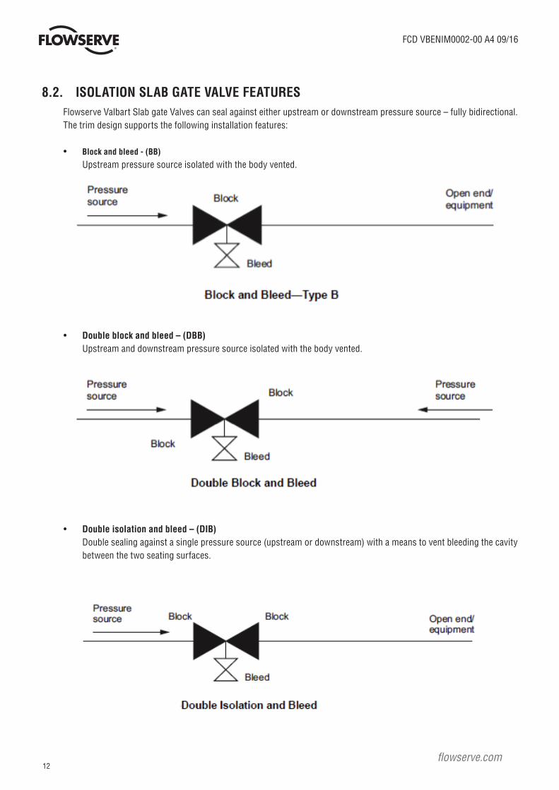
8.2. ISOLATION SLAB GATE VALVE FEATURESFlowserve Valbart Slab gate Valves can seal against either upstream or downstream pressure source – fully bidirectional.The trim design supports the following installation features:
• Block and bleed - (BB)
Upstream pressure source isolated with the body vented.
• Double block and bleed – (DBB) Upstream and downstream pressure source isolated with the body vented.
• Double isolation and bleed – (DIB) Double sealing against a single pressure source (upstream or downstream) with a means to vent bleeding the cavity
between the two seating surfaces.

13
FCD VBENIM0002-00 A4 09/16 FCD VBENIM0002-00 A4 09/16
9. VALVE LEAKAGEFor valve of standard application, any leakage on the stem and/or on the seat can be temporarily and easily reduced or stopped, before the maintenance shut down operation, by injecting sealant grease through the stem grease fitting (19) or seat grease fitting (15) (if provided). The choice of the grease is related to the service of the valve (media, temperature, pressure) and it is customer responsibility. WARNING: It is mandatory that this operation will be carried out by skilled personnel aware of safety rules and field techniques. For any special application, such as hydrogen or oxygen service, no grease shall be used at all and the injection points are not provided.
10. VENTING/BLEEDING OF THE VALVE BODY CAVITYValve body cavity may be vented/bleeded (with the slab in fully closed position).The vent / bleeding must be performed every time the valve is removed from the pipeline. The vent / bleeding should also be performed in order to check valve seat integrity. This procedure may be applied also in fully open position if the valve is not equipped with equalizing hole (please check the presence of this feature on the applicable valve drawing).In order to remove the pressure from the body cavity the valve must be equipped with vent/drain bleeder (Item 18) and the following procedure must be strictly followed:
WARNING:• Venting/bleeding of the body cavity must be performed by skilled personal, dressing all the necessary safety
equipment (glass, helmet, gloves and earplugs).• Before any operation on the valve this must be authorized by safety manager of the plant.• Bleeding to atmosphere of hydrocarbon products must be permitted by local law or safety regulation.• Not respecting of authorization or safety procedure may expose the personal to injury.
1. Std Flowserve Valbart vent/bleeders are supplied for venting/bleeding to atmosphere, with a lateral exhaust port.
2. Before bleeding check the position of the exhaust port in order to avoid direct exposure to bleed flow. Please note that any particles inside the cavity can be blow out at high velocity.
If necessary re-orient the bleeder exhaust port.
3. To open the vent/bleeder the needle plug must be rotate slowly anticlockwise using an Allen screw wrench.
DANGER: Be sure that doing this operation the vent/bleeder is not rotating against its connection to the body.
After a variable period of time (as a function of the volume of the valve body cavity), the flow through the bleeder is stopped this means that seats are performing a good tightness.
In case that after a reasonable period of time the flow through the bleeder is maintaining a high velocity this means that the valve is not sealing properly.
STOP!
STOP!

14
FCD VBENIM0002-00 A4 09/16
flowserve.com
11. MAINTENANCE DANGER: Depressurize the line before starting any maintenance. Failure to do so may cause serious personal injury and-or
equipment damage.
These instructions cover the maintenance and repair operations that may be carried out on Slab Gate Valves and are applicable to those with the operator mounted directly on the adapter plate without stem extension.
Any servicing not covered by these instructions must be made in an authorised service center after preliminary approval has been given by Flowserve.
These instructions are applicable to Slab gate Valves covered by general arrangement drawings herewith attached.
11.1. DISASSEMBLY TOOLS
Tool Quantity Notes
Torque wrench
1• Required for ALL the valve bolted
connection.
Male metric eyebolt
1
• M12 for valve size ≤ 20”• M16 for valve size ≤ 24”• M16 for valve 30”-150#
• M24 for valves 30”-300# and 600#
Male inch eyebolt
2
• ½” for valve size ≤ 10”• 5/8” for valve size ≤ 24” and 30”-150#• 7/8” for valve 30”-300#• 1” for valves 30”-600#
Female metric eyebolt
2
• M8 for valve size ≤ 20”• M10 for valve size ≤ 30”• M12 for valve size > 30”
Seat lifter tool
2• M8 for valve size ≤ 20”/Length:900mm• M10 for valve size ≤ 30”/ Length:1400mm• M12 for valve size > 30”/ Length:1800mm
15
FCD VBENIM0002-00 A4 09/16 FCD VBENIM0002-00 A4 09/16
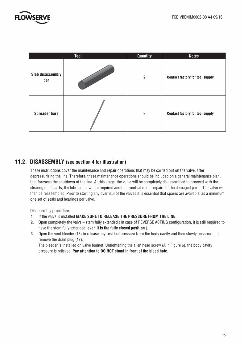
Tool Quantity Notes
Slab disassembly bar
2 Contact factory for tool supply
Spreader bars 2 Contact factory for tool supply
11.2. DISASSEMBLY (see section 4 for illustration) These instructions cover the maintenance and repair operations that may be carried out on the valve, after
depressurizing the line. Therefore, these maintenance operations should be included on a general maintenance plan, that foresees the shutdown of the line. At this stage, the valve will be completely disassembled to proceed with the clearing of all parts, the lubrication where required and the eventual minor repairs of the damaged parts. The valve will then be reassembled. Prior to starting any overhaul of the valves it is essential that spares are available: as a minimum one set of seals and bearings per valve.
Disassembly procedure:1. If the valve is installed MAKE SURE TO RELEASE THE PRESSURE FROM THE LINE.2. Open completely the valve – stem fully extended ( in case of REVERSE ACTING configuration, it is still required to
have the stem fully extended, even it is the fully closed position ).3. Open the vent bleeder (18) to release any residual pressure from the body cavity and then slowly unscrew and
remove the drain plug (17). The bleeder is installed on valve bonnet. Untightening the allen head screw (A in Figure 6), the body cavity
pressure is relieved. Pay attention to DO NOT stand in front of the bleed hole.

16
FCD VBENIM0002-00 A4 09/16
flowserve.com
4. Close the valve (in case of REVERSE acting slab gate valve it is required to have the stem in the lowest down position)5. Remove the valve from the line6. If present, remove the stem protection and the position indicator rod from the OPERATOR7. Remove the operator, ( gearbox or actuator ) from the valve yoke (Figure 7)
Figure 6 - Bleeder detail
BLEED HOLE

17
FCD VBENIM0002-00 A4 09/16 FCD VBENIM0002-00 A4 09/16
Figure 7 Operator removal sequence
Figure 8 - Yoke bolting removal
8. Remove the yoke flange bolting as shown in Figure 8
POSITIONINDICATOR ROD
STEMPROTECTIONTUBE
OPERATOR

18
FCD VBENIM0002-00 A4 09/16
flowserve.com
9. Hook the yoke operator flange as shown in the following Figure 9, lift and remove the yoke from the valve bonnet. Stem fire safe gasket and stem bearing can be now disassembled
10. Remove the bonnet bolting (Item N° 20 and 21)
11. Screw two male eyebolt into the bonnet tapered holes. Lift the bonnet and remove it from stem (ref. to Figure 10 )
Figure 9 - Yoke disassembly and stem fire safe gasket and bearing removal.

19
FCD VBENIM0002-00 A4 09/16 FCD VBENIM0002-00 A4 09/16
12. Screw an eyebolt into the tapped hole on the top of the stem and fasten it and lift the stem and gate assembly till the
two grooves in the upper side of the gate will be accessible from the top of the body (Figure 11 - A)
Figure 11 - Slab gate disassembly according to steps n° 12, 13 and 14.
Figure 10 - Bonnet disassembly
13. Insert two steel bars in the two groove of the gate (Figure 11-B)
14. Pull down the assembly till until the steel bars lean on the valve body (Figure 11-C)
15. Move sidewise the stem releasing the stem head from its housing in the gate (Figure 12)
B0NNET LIFTING POINTS
STEM LIFTING POINT
SLAB GATE ASSEMBLY GROOVES
STEEL ROUND BARS

20
FCD VBENIM0002-00 A4 09/16
flowserve.com
16. Remove stem and seat grease fittings (19 and 16) and the vent fitting (18) from the bonnet, to clean.
17. While the slab still inside the body supported as shown in Figure 12, screw an male eyebolt in the tapered hole placed
at the guide upper surface (Figure 13). By means of a crane, lift the guide until its complete disengagement from the
body. Repeat the same procedure for the gate at the opposite side – N°2.
Figure 12 - Stem head disengaging.

21
FCD VBENIM0002-00 A4 09/16 FCD VBENIM0002-00 A4 09/16
18. Wedge the small end of the seat spreader tools between the seats tool lugs and drive the tools down simultaneously (for about 50[mm]), pushing the seat back in the recess (Figure 14).
Figure 13 - Gate guides removal
Figure 14 - Seat spreader tools use.
GATE GUIDE No 1
GATE GUIDE No 2
SEATLUGS
SPREADERTOOLS

22
FCD VBENIM0002-00 A4 09/16
flowserve.com
19. Remove the gate from the body (Figure 14) by screwing N°2 eyebolt in the slab side holes, as marked in Figure 14.
For valve size of 12” and below the side holes are not provided. Remove the socket head screw from the side holes
and install N°2 male eyebolts in both M8 tapped holes.
• Stem gaskets (13 and 14)
• Yoke to bonnet gasket (15)
• Yoke to operator gasket, if present
• Body to bonnet gaskets (12 and 22)
Figure 16 - Seat lifter tool installation and use
20. Screw the seat lifter tool into each seat tapered hole, located in the seat top flattened surface.
21. Remove the seat spreader tools (Figure 14).
SIDE HOLES
Figure 15 - Slab gate removal.

23
FCD VBENIM0002-00 A4 09/16 FCD VBENIM0002-00 A4 09/16
22. Remove the seats (4) prying out the seat recess if necessary (Figure 17)
Figure 17 - Seat disassembly from the body
Figure 18 - Seat gaskets and springs stripping.
NOTE: Remove seat smoothly to avoid dropping of seat springs (8) inside the valve body.
23. At this point it is possible to remove and replace the following components (Figure 18)
• Seat o-rings (9, 10, 11)
• Seat springs (8)

24
FCD VBENIM0002-00 A4 09/16
flowserve.com
11.3. INSPECTION AND MAINTENANCE After the complete disassembly, all components of the valve should be cleaned, in order to remove any debris or corrosive products.
For a complete cleaning procedure, carry out the following operations:
NOTE: Abrasive cleaning should never be used, especially on sealing area. If water jetting is used, dry as far as possible with compressed air.
1. Wipe the metal parts with solvent by means of soft cloth.
2. Wipe O-rings and gaskets by means of soft cloth.
3. Check O-rings and gaskets, seat rings, stem and obturator.
4. Replace the defective part with a new one.
5. If present, clean the grease channels as far as possible.
6. If present, clean the grease injection fittings and the relief valve on the body
After cleaning, all valve components should be inspected for damages. If any damage is found, proceed with the repair where possible, or with substitution of the parts. For a complete inspection procedure, the following operations shall be carried out:
• Check the metallic parts for damages (dents, scorings, etc.) along the sealing surfaces and on moving surfaces. Particular attention should be paid to surface nicks and corner damage.
• Make sure that the sealing rings and gaskets are not slashed, extruded and/or otherwise damaged.
• Check the surfaces of the bearings and the seat components.
• Inspect all spares that are going to be used to ensure damage has not occurred in storage or transportation.
NOTE: After every disassembly it is recommended to replace the O-rings and gaskets using factory supplied repair kits. Do not use O-rings and gaskets with dimensions different from the original ones.
12. REASSEMBLY Assuming that all components have been visually inspected and accepted by a competent person, the reassembly of the valve may
proceed. To ensure that the valve performs satisfactorily in service, it is essential it is assembled with care and attention to details. Particular care must be paid that all reference marks are properly lined up during the reassembly.
During the reassembly of the valve, take care when rigging the heavy weights involved in some components.
Use wire slings only when lifting via an eyebolt and hook, otherwise use nylon slings.
To re-assemble the valve follow the disassembly steps backwards. For bolt tightening refer to section 16 - Bolting”.
NOTE: During re-assembly take care to not damage O-rings. In the case of valves equipped with operator do not move, in any case, the operator end stops.
CAUTION: If the valve is for oxygen or hydrogen application please reassemble the valve in controlled environment and do not use any grease at all.

25
FCD VBENIM0002-00 A4 09/16 FCD VBENIM0002-00 A4 09/16
13. RECOMMENDED ASSEMBLY LUBRICANTS
14. MINOR REPAIRS If any damage is found, the minor repairs should be carried out by competent persons. For major repair contact Flowserve.
The minor repairs, that may be carried out at site by maintenance personnel, shall be in accordance with the following points:
• Rectify by normal good engineering practice the damage on metallic surfaces.
• Remove by using mild abrasive on surface nicks, especially on gate and stem.
• Remove by using mild abrasive or with a bearing scraper all corner damages.
• Replace all faulty parts and components.
15. PREVENTIVE MAINTENANCE SCHEDULE CAUTION: Do not modify the actuator stops controlling the opening and closing position of the valve
15.1. LUBRICATION / SEALING ON STEM AREA Flowserve Valbart slab gate valves have been designed and tested in such a way that they do not require the use of lubricants / sealants
during their normal service operation. The implementation of a regular lubrication program in the stem area extends the service life of
the valve and improves its performance. A lubrication schedule based on the frequency of operations and on the severity of the service
is recommended. However, the lubrication in the stem area should be carried out in the following cases:
• Every six months between the installation and start up
• Before operating the valve if the valve has been left in its position, either fully open or fully closed, for long periods
without moving it
• As soon as an increase of stem movement resistance is noticed.
• In case of one of the above condition takes places, grease should be injected as follows
• Inject lubricant grease on the stem area through the grease fitting (19)
• If valve is provided with a seat grease injection system, inject lubricant grease on the seat area through the seat grease fitting (16).
Purpose Lubricant
General assembly lubricant Molikote 577 *
Antiseizing Molikote 1000 *
* Or equivalent

26
FCD VBENIM0002-00 A4 09/16
flowserve.com
16. BOLTING16.1 RECOMMENDATION
1 Put some grease on both the bolting thread and nut bearing surface.
2 Tighten the bolts with cross passes (an example of sequence is indicated in the next paragraph).
3 During tightening make sure that the faces of flange remain perfectly parallel.
NOTE: For a better performance of the joint carry out the tightening step by step, starting with the sequence using a torque value approximately one third of the maximum torque, then repeat the sequences increasing the torque until reaching the maximum torque value.
16.2. BOLT TIGHTENING SEQUENCE
Number each bolt location starting from number 1 and continuing to n, numbering them sequentially in a clockwise manner.
Each bonnet side, short and long, has its own numbering sequence, which always starts from the first bolt on the vertical axis
right side as shown below.
Figure 19 - Short side numbering sequence. DO NOT CONSIDER bolting on long side.
BONNET TOP VIEW
BOLT NO1LOCATION
Numbered sequentiallyCLOCKWISE
1
2
n

27
FCD VBENIM0002-00 A4 09/16 FCD VBENIM0002-00 A4 09/16
BONNET TOP VIEW
Figure 20 - Long side numbering sequence. DO NOT CONSIDER bolting on short side.
NOTE:
• The bolts cross-pattern tightening sequence, on each side, shall be in accordance with the following table.
• Always alternate long side and short side tightening passes.
• Apply 1/3 of the target torque for each round of tightening sequence.
• Once reaching the 100% of target torque continue tightening the bolts. Tighten on a circular clockwise pattern until no further nut rotation occurs.
No. Of Bolts (n) Long side sequence Short side sequence
2 - 1-2
4 1-3-2-4 1-3-2-4
6 - 1-4-2-5 6-3
8 1-5-3-7 2-6-4-8 –
12 1-7-4-10 2-8-5-11 3-9-6-12 –
16 1-9-5-13 3-11-7-15 2-10-6-14 4-12-8-16 –
20 1-11-6-16 3-13-8-18 5-15-10-20 2-17-7-17 4-14-9-19 –
241-13-7-19 4-16-10-22 2-14-8-20 5-17-11-23 3-15-9-21
6-18-12-24–
281-15-8-22 4-18-11-25 6-20-13-27 2-16-9-23 5-19-12-26
7-21-14-28 3-17-10-24–
321-17-9-25 5-21-13-29 3-19-11-27 7-23-15-31 2-18-10-
26 6-22-14-30 4-20-12-28 8-34-16-32 –
361-2-3 19-20-21 10-11-12 28-29-30 4-5-6 22-23-
24 13-14-15 31-32-33 7-8-9 25-26-27 16-17-18
34-35-36
–
401-2-3-4 21-22-23-24 13-14-15-16 33-34-35-36 5-6-7-8
25-26-27-28 17-18-19-20 37-38-39-40 9-10-11-12
29-30-31-32
–
Note 1: Arrow separates cross tightening passes
“-“: Does not apply to any project
16.3 Bolt tightening torque values
BOLT NO1LOCATION
Numbered sequentiallyCLOCKWISE
1 2 n
28
FCD VBENIM0002-00 A4 09/16
flowserve.com
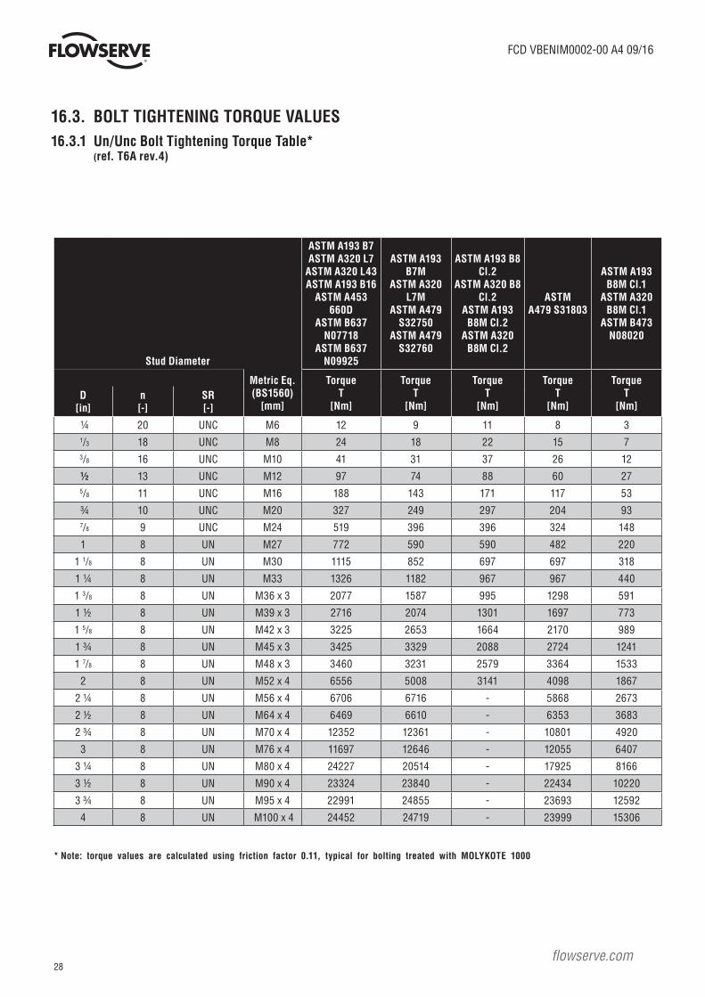
16.3. BOLT TIGHTENING TORQUE VALUES16.3.1 Un/Unc Bolt Tightening Torque Table* (ref. T6A rev.4)
Stud Diameter
ASTM A193 B7ASTM A320 L7
ASTM A320 L43ASTM A193 B16
ASTM A453 660D
ASTM B637 N07718
ASTM B637 N09925
ASTM A193 B7M
ASTM A320 L7M
ASTM A479 S32750
ASTM A479 S32760
ASTM A193 B8 Cl.2
ASTM A320 B8 Cl.2
ASTM A193 B8M Cl.2
ASTM A320 B8M Cl.2
ASTMA479 S31803
ASTM A193 B8M Cl.1
ASTM A320 B8M Cl.1
ASTM B473 N08020
Metric Eq.(BS1560)
[mm]
TorqueT
[Nm]
TorqueT
[Nm]
TorqueT
[Nm]
TorqueT
[Nm]
TorqueT
[Nm]D
[in]n[-]
SR[-]
¼ 20 UNC M6 12 9 11 8 3
1/3 18 UNC M8 24 18 22 15 7
3/8 16 UNC M10 41 31 37 26 12
½ 13 UNC M12 97 74 88 60 27
5/8 11 UNC M16 188 143 171 117 53
¾ 10 UNC M20 327 249 297 204 93
7/8 9 UNC M24 519 396 396 324 148
1 8 UN M27 772 590 590 482 220
1 1/8 8 UN M30 1115 852 697 697 318
1 ¼ 8 UN M33 1326 1182 967 967 440
1 3/8 8 UN M36 x 3 2077 1587 995 1298 591
1 ½ 8 UN M39 x 3 2716 2074 1301 1697 773
1 5/8 8 UN M42 x 3 3225 2653 1664 2170 989
1 ¾ 8 UN M45 x 3 3425 3329 2088 2724 1241
1 7/8 8 UN M48 x 3 3460 3231 2579 3364 1533
2 8 UN M52 x 4 6556 5008 3141 4098 1867
2 ¼ 8 UN M56 x 4 6706 6716 - 5868 2673
2 ½ 8 UN M64 x 4 6469 6610 - 6353 3683
2 ¾ 8 UN M70 x 4 12352 12361 - 10801 4920
3 8 UN M76 x 4 11697 12646 - 12055 6407
3 ¼ 8 UN M80 x 4 24227 20514 - 17925 8166
3 ½ 8 UN M90 x 4 23324 23840 - 22434 10220
3 ¾ 8 UN M95 x 4 22991 24855 - 23693 12592
4 8 UN M100 x 4 24452 24719 - 23999 15306
* Note: torque values are calculated using friction factor 0.11, typical for bolting treated with MOLYKOTE 1000

29
FCD VBENIM0002-00 A4 09/16 FCD VBENIM0002-00 A4 09/16
Diameter
ASTM A193 B7ASTM A320 L7
ASTM A320 L43ASTM A193 B16
ASTM A453 660DASTM B637
N07718ASTM B637
N09925
ASTM A193 B7MASTM A320 L7M
ASTM A479 S32750
ASTM A479 S32760
ASTMA193 B8M Cl.2A320 B8M Cl.2A193 B8 Cl.2A320 B8 Cl.2
ASTMA479 S31803
ASTM A193 B8M Cl.1
ASTM A320 B8M Cl.1
ASTM B473 N08020
TorqueT
[Nm]
TorqueT
[Nm]
TorqueT
[Nm]
TorqueT
[Nm]
TorqueT
[Nm]M[-]
D[mm]
M8 8 30 23 27 19 8
M10 10 58 45 53 36 17
M12 12 100 76 91 62 28
M14 14 139 106 127 87 40
M16 16 213 163 194 133 61
M18 18 297 227 271 186 85
M20 20 417 318 379 261 119
M24 24 720 550 550 450 205
M27 27 1044 797 652 652 297
M30 30 1425 1089 891 891 406
M33 33 1933 1476 926 1208 550
M36 36 2483 1897 1190 1552 707
16.3.2 Capscrew tightening torque table* (ref. T6A rev.4)
* Note: torque values are calculated using friction factor 0.13, typical for dry threads

30
FCD VBENIM0002-00 A4 09/16
flowserve.com
17. RECOMMENDED VALVE INSPECTION AND MAINTENANCE
17.1. PREVENTIVE ACTIONS
NOTE:
1. Verify at least once a year the tightness of bolts, drain, vent and any other device fitted to the valve
2. Every five years disassemble the critical service valves and/or actuated valves, verifying the sealing surface and lapping them again if necessary. Change all gaskets and sealing elastomers.
3. For actuated valves, in addition to the above please refer to the actuator maintenance manual.
17.2. VALVE TESTING AND INSPECTION
CAUTION:1. Perform a Visual inspection at least once a year in order to verify that there are no external leakages and, with valve
in closed position, check if there are leakages between gate and seats. If leakage is present use a seat and /or stem sealant injector device(s) to stop the leakage. The sealant injection is to be considered as an emergency operation to stop leakage up to the next planned maintenance job. If the leakage does not stop, follow the maintenance procedure for the replacement of all gaskets and sealing elastomers.
2. For actuated valves, in addition to the above please refer to the actuator maintenance manual.3. Verify in a safe way at least once a year that there is no external and or internal corrosion.4. In order to verify the correct operability of the valves/actuators, once a year, carry out a full stroke test (From Fully
OPEN to Fully CLOSE to fully OPEN position or from Fully CLOSE to Fully OPEN to fully CLOSE position) starting from the normal valve operation position.

31
FCD VBENIM0002-00 A4 09/16 FCD VBENIM0002-00 A4 09/16
32
FCD VBENIM0002-00 A4 09/16
flowserve.com
To find your local Flowserve representative or for more information about Flowserve Corporation, visit www.flowserve.com or call USA 1 800 225 6989
FCD VBENIM0002-00 A4 09/16 AQ
Flowserve Corporation has established industry leadership in the design and manufacture of its products. When properly selected, this Flowserve product is designed to perform its intended function safely during its useful life. However, the purchaser or user of Flowserve products should be aware that Flowserve products might be used in numerous applications under a wide variety of industrial service conditions. Although Flowserve can (and often does) provide general guidelines, it cannot provide specific data and warnings for all possible applications. The purchaser/user must therefore assume the ultimate responsibility for the proper sizing and selection, installation, operation, and maintenance of Flowserve products. The purchaser/user should read and understand the Installation Operation Maintenance (IOM) instructions included with the product, and train its employees and contractors in the safe use of Flowserve products in connection with the specific application.
While the information and specifications contained in this literature are believed to be accurate, they are supplied for informative purposes only and should not be considered certified or as a guarantee of satisfactory results by reliance thereon. Nothing contained herein is to be construed as a warranty or guarantee, express or implied, regarding any matter with respect to this product. Because Flowserve is continually improving and upgrading its product design, the specifications, dimensions and information contained herein are subject to change without notice. Should any question arise concerning these provisions, the purchaser/user should contact Flowserve Corporation at any one of its worldwide operations or offices.
© 2016 Flowserve Corporation, Irving, Texas, USA. Flowserve is a registered trademark of Flowserve Corporation.
ItalyFlowserve Valbart SRLVia delle Industrie, 9/5 - 20883 Mezzago (MB) ItalyTelephone: +39 039 624111 Fax: +39 039 6241178 E-mail: [email protected]
USAFlowserve Corp.3993 West Sam Houston Parkway North, Suite 100Houston, Texas 77043Telephone: +1 713 863 9180