fd, dfd, ssfd, ssdfd, & kfd models - stinebaugh.com … · accordance with fire damper...
TRANSCRIPT
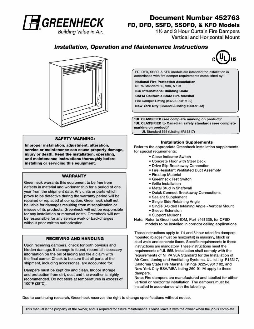
Installation, Operation and Maintenance Instructions
This manual is the property of the owner, and is required for future maintenance. Please leave it with the owner when the job is complete.
“UL CLASSIFIED (see complete marking on product)”“UL CLASSIFIED to Canadian safety standards (see complete marking on product)” UL Standard 555 (Listing #R13317)
RECEIvIng AnD HAnDLIng
Upon receiving dampers, check for both obvious and hidden damage. If damage is found, record all necessary information on the bill of lading and file a claim with the final carrier. Check to be sure that all parts of the shipment, including accessories, are accounted for.
Dampers must be kept dry and clean. Indoor storage and protection from dirt, dust and the weather is highly recommended. Do not store at temperatures in excess of 100°F (38°C).
FD, DFD, SSFD, & KFD models are intended for installation in accordance with fire damper requirements established by:
national Fire Protection Association NFPA Standard 80, 90A, & 101
IBC International Building Code
CSFM California State Fire Marshal
Fire Damper Listing (#3225-0981:102)
new York City (BSA/MEA listing #260-91-M)
Document number 452763FD, DFD, SSFD, SSDFD, & KFD Models
11/2 and 3 Hour Curtain Fire DampersVertical and Horizontal Mount
SAFEtY WARnIng:
Improper installation, adjustment, alteration, service or maintenance can cause property damage, injury or death. Read the installation, operating, and maintenance instructions thoroughly before installing or servicing this equipment.
WARRAntY
Greenheck warrants this equipment to be free from defects in material and workmanship for a period of one year from the shipment date. Any units or parts which prove to be defective during the warranty period will be repaired or replaced at our option. Greenheck shall not be liable for damages resulting from misapplication or misuse of its products. Greenheck will not be responsible for any installation or removal costs. Greenheck will not be responsible for any service work or backcharges without prior written authorization.
These instructions apply to 11/2 and 3 hour rated fire dampers mounted (blades must be horizontal) in masonry, block or stud walls and concrete floors. Specific requirements in these instructions are mandatory. These instructions meet the requirements of UL 555. Installation shall comply with the requirements of NFPA 90A Standard for the Installation of Air Conditioning and Ventilating Systems. UL listing R13317, California State Fire Marshal listings 3225-0981:102, and New York City BSA/MEA listing 260-91-M apply to these dampers.Note: Fire dampers are manufactured and labelled for either vertical or horizontal installation. The dampers must be installed in accordance with the labelling.
Installation SupplementsRefer to the appropriate Greenheck installation supplements for special requirements: • Close Indicator Switch • Concrete Floor with Steel Deck • Drive Slip Breakaway Connection • Fire Resistant Ventilated Duct Assembly • Firestop Material • Greenheck Test Switch • Grille Installation • Metal Stud in Shaftwall • Quick Connect Breakaway Connections • Sealant Supplement • Single Side Retaining Angle • Single 3-Sided Retaining Angle - Vertical Mount • Sleeve Extension • Support MullionsNote: Refer to Greenheck IOM, Part #461335, for CFSD
models to be installed in corridor ceiling applications.
Due to continuing research, Greenheck reserves the right to change specifications without notice.
®
Pre-Installation guidelinesThe basic intent of a proper installation is to secure the fire damper in, not to, the opening in such a manner as to prevent distortion and disruption of damper operation. This is accomplished by allowing the fire damper in rated separation openings to expand and for the connecting duct to separate in the event of the collapse of the hanging system. The following items will aid in completing the damper installation in a timely and effective manner.
1) Check the schedules for proper damper locations within the building. Visually inspect the damper for damage and verify that the fusible link is in place or has not activated. Never install a fire damper without the proper UL approved fusible link in place. If damper is furnished with fusible link, visually inspect the link to verify its not missing or broken. Replace link as necessary.
2) Lift or handle damper using sleeve or frame. Do not lift damper using blades.
3) Damper has label on outside of sleeve indicating a ‘No Screw’ area. Do not install screws into this area as screws may interfere with unexposed blade linkage and prevent damper blades from opening and/or closing.
4) Damper has label indicating position of damper and sleeve assembly in the wall. Install accordingly to comply with manufacturer’s appropriate UL Classification file number.
5) Damper must be installed into duct or opening square and free of twist or other misalignment. Damper must not be squeezed or stretched into duct or opening. Out of square, racked, twisted or misaligned
installations can cause excessive leakage and/or torque requirements to exceed damper/actuator design.
6) Damper must be kept clean and protected from dirt, dust and other foreign materials prior to and after installation. Examples of such foreign materials include but are not limited to:
a) Mortar dust b) Drywall dust c) Firesafing materials d) Wall texture e) Paint overspray
7) Damper should be sufficiently covered as to prevent overspray if wall texturing or spray painting will be performed within 5 feet of the damper. Excessive dirt or foreign material deposits on damper can cause excessive leakage and/or torque requirements to exceed damper/actuator design.
8) Caulking is not necessary, nor is it allowed, between the damper sleeve and the wall or floor opening (annular space). However, caulking may be applied to the retaining angles.
9) ACCESS: Suitable access (such that fusible links can be maintained, etc.) must be provided for damper inspection and servicing. Where it is not possible to achieve sufficient size access, it will be necessary to install a removable section of duct. (Refer to NFPA 90A).
10) The Code Authority Having Jurisdiction (AHJ) must evaluate and provide approval of final installation where variations to these instructions are necessary.
table of ContentsPre-Installation Guidelines.............................................................................................................................................................. 2 Installation ...................................................................................................................................................................................2-8 • Clearances Required Between Fire Damper Sleeves and Wall/Floor Openings............................................................ 2 • Sleeve Length and Wall Thickness .............................................................. .................................................................4 • Duct to Sleeve Connections .......................................................................................................................................3-4 • Securing the Damper/Sleeve Assembly to Wall and Floor Openings ....................................................... .....................4 • Installing Multiple Damper Section Assemblies ........................................................................................................... 5 • Recommended Preparation of Openings in Wood and Metal Stud Walls ...................................................................6-7 • Breakaway Connections .................................................................... ...........................................................................7
1. CLEARAnCES REQUIRED BEtWEEn FIRE DAMPER SLEEvES AnD WALL/FLOOR OPEnIngS
Fire damper and sleeve assemblies expand during periods of intense heat. Therefore it is essential that openings in walls or floors be larger than the fire damper and sleeve assembly to allow for this expansion. Minimum clearances required between the outside of fire damper sleeve assemblies and wall/floor openings are:
• Galvanized steel fire dampers and sleeves: 1/8 in. (3mm) per foot of damper width and 1/8 in. (3mm) per foot height with a minimum clearance of 1/4 in. (6mm) Recommended clearances, for width and/or height dimensions of:
1) 48 in. (1219mm) or less: 1/2 in. (13mm) clearance 2) More than 48 in. (1219mm) and 96 in. (2438mm)
or less: 1 in. (25mm) clearance
3) More than 96 in. (2438mm): 1 1/2 in. (38mm) clearance
• Stainless steel fire dampers and stainless steel or galvanized sleeves: 3/16 in. (4.8mm) per foot of damper width and height with a minimum clearance of 1/4 in. (6mm), maximum of 2 in. (51mm). Recommended clearances, for width and/or height dimensions of:
1) 48 in. (1219mm) or less: 3/4 in. (19mm) clearance 2) More than 48 in. (1219mm) and 96 in. (2438mm) or
less: 1 1/2 in. (38mm) clearance 3) More than 96 in. (2438mm): 2 in. (51mm)
clearance These are total clearances (ignoring fastener heads)
and do not need to be equally spaced around the damper. Refer to Section 4 and Figure 6 for additional installation considerations.
2
Example: A 12 in. x 12 in. (305mm x 305mm) damper would re-quire a minimum clearance of 1/4 in. (6mm) on width and 1/4 in. (6mm) on height
A 48 in. x 12 in. (1219mm x 305mm) damper would require a minimum clearance of 1/2 in. (13mm) on width and 1/4 in. (6mm) on height.
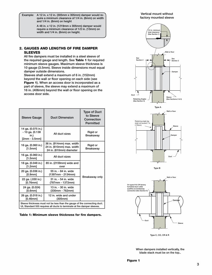
2. gAUgES AnD LEngtHS OF FIRE DAMPER SLEEvES
All fire dampers must be installed in a steel sleeve of the required gauge and length. See table 1 for required minimum sleeve gauges. Maximum sleeve thickness is 10 gauge (3.5mm). Sleeve inside dimensions must equal damper outside dimensions.
Sleeves shall extend a maximum of 6 in. (152mm) beyond the wall or floor opening on each side (see Figure 1). When an access door is incorporated as a part of sleeve, the sleeve may extend a maximum of 16 in. (406mm) beyond the wall or floor opening on the access door side.
table 1: Minimum sleeve thickness for fire dampers.
Sleeve Gauge Duct Dimension
Type of Duct to Sleeve
Connection Permitted
14 ga. (0.075 in.) - 10 ga. (0.138
in.)[2mm - 3.5mm]
All duct sizesRigid or
Breakaway
16 ga. (0.060 in.)[1.5mm]
36 in. (914mm) max. width24 in. (610mm) max. width24 in. (610mm) diameter
Rigid or Breakaway
16 ga. (0.060 in.)[1.5mm]
All duct sizes
Breakaway only
18 ga. (0.048 in.)[1.2mm]
85 in. (2159mm) wide and over
20 ga. (0.036 in.)[0.9mm]
55 in. - 84 in. wide(1397mm - 2134mm)
22 ga. (.030 in.)[0.76mm]
31 in. - 54 in. wide(787mm - 1372mm)
24 ga. (0.024)[0.6mm]
13 in. - 30 in. wide(330mm - 762mm)
26 ga. (0.018 in.)[0.46mm]
12 in. wide and under(305mm)
Sleeve thickness must not be less than the gauge of the connecting duct.UL Standard 555 requires all ducts to terminate at fire damper sleeves.
Damper
1/4 in. minimumtotal clearance(See Section 1)
See Section 2
See Section 2
Wall or floor
Wall or floor
Wall or floor
Damper
Damper
Duct
Duct
Duct
Retaining Angles(See Section 4)
Sleeve(See Sections 2 & 3)
Sleeve
Sleeve
On types R & CR factoryfurnished duct collarqualifies as breakawayconneciton (See Section 5)
1 in. min. overlapFour sides
Mounting Angles(See Para. 4)
1/4 in. minimum total clearance(See Para. 1)
Retaining angle leg shall not exceed 7 in. (178mm)
Type C, CO, CR & R
Type B
Vertical mount without factory mounted sleeve
Type A
When dampers installed vertically, the blade stack must be on the top..
Figure 13
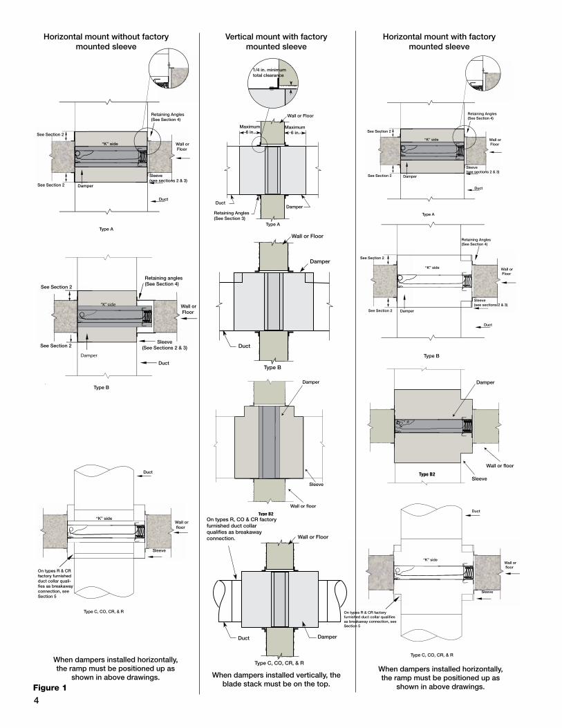
Horizontal mount with factory mounted sleeve
Wall or Floor
Retaining Angles(See Section 4)
Sleeve(see sections 2 & 3)
Duct
“K” side
Damper
See Section 2
See Section 2
Type A
Wall or Floor
Retaining Angles(See Section 4)
Sleeve(see sections 2 & 3)
Duct
“K” side
Damper
See Section 2
See Section 2
Type B
Wall or floor
On types R & CR factory furnished duct collar qualifies as breakaway connection, see Section 5
Duct
Sleeve
Type C, CO, CR, & R
“K” side
When dampers installed horizontally, the ramp must be positioned up as
shown in above drawings.
1/4 in. minimumtotal clearance
Wall or Floor
Maximum 6 in.
Maximum 6 in.
Duct
Duct
Duct
Damper
Damper
Damper
Wall or Floor
Wall or Floor
Retaining Angles (See Section 3)
Type A
Type B
On types R, CO & CR factoryfurnished duct collarqualifies as breakaway connection.
Type C, CO, CR, & R
1/4 in. minimumtotal clearance
Wall or Floor
Maximum 6 in.
Maximum 6 in.
Duct
Duct
Duct
Damper
Damper
Damper
Wall or Floor
Wall or Floor
Retaining Angles (See Section 3)
Type A
Type B
On types R, CO & CR factoryfurnished duct collarqualifies as breakaway connection.
Type C, CO, CR, & R
1/4 in. minimumtotal clearance
Wall or Floor
Maximum 6 in.
Maximum 6 in.
Duct
Duct
Duct
Damper
Damper
Damper
Wall or Floor
Wall or Floor
Retaining Angles (See Section 3)
Type A
Type B
On types R, CO & CR factoryfurnished duct collarqualifies as breakaway connection.
Type C, CO, CR, & R
Vertical mount with factory mounted sleeve
Wall or floor
On types R & CR factory furnished duct collar quali-fies as breakaway connection, see Section 5
Duct
Sleeve
Type C, CO, CR, & R
“K” side
Sleeve(See Sections 2 & 3)
Duct
Retaining angles(See Section 4)
Type B
See Section 2
See Section 2
“K” side
Damper
Wall or Floor
Wall or Floor
Retaining Angles(See Section 4)
Sleeve(see sections 2 & 3)
Duct
“K” side
Damper
See Section 2
See Section 2
Type A
Horizontal mount without factory mounted sleeve
When dampers installed horizontally, the ramp must be positioned up as
shown in above drawings. When dampers installed vertically, the blade stack must be on the top.Figure 1
Type B2
Type B2
Wall or floor
Damper
Sleeve
Wall or floor
Damper
Sleeve
Type B2
Type B2
Wall or floor
Damper
Sleeve
Wall or floor
Damper
Sleeve
4
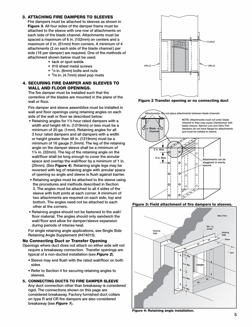
3. AttACHIng FIRE DAMPERS tO SLEEvES Fire dampers must be attached to sleeves as shown in
Figure 3. All four sides of the damper frame must be attached to the sleeve with one row of attachments on each side of the blade channel. Attachments must be spaced a maximum of 6 in. (152mm) on centers and a maximum of 2 in. (51mm) from corners. A minimum of 4 attachments (2 on each side of the blade channel ) per side (16 per damper) are required. One of the methods of attachment shown below must be used.
• tack or spot welds• #10 sheet metal screws • 1/4 in. (6mm) bolts and nuts• 3/16 in. (4.7mm) steel pop rivets
4. SECURIng FIRE DAMPER AnD SLEEvES tO WALL AnD FLOOR OPEnIngS.
The fire damper must be installed such that the centerline of the blades are mounted in the plane of the wall or floor.
Fire damper and sleeve assemblies must be installed in wall and floor openings using retaining angles on each side of the wall or floor as described below: • Retaining angles for 11/2 hour rated dampers with a
width and height 48 in. (1219mm) or less must be a minimum of 20 ga. (1mm). Retaining angles for all 3 hour rated dampers and all dampers with a width or height greater than 48 in. (1219mm) must be a minimum of 16 gauge (1.5mm). The leg of the retaining angle on the damper sleeve shall be a minimum of 11/4 in. (32mm). The leg of the retaining angle on the wall/floor shall be long enough to cover the annular space and overlap the wall/floor by a minimum of 1 in. (25mm). (See Figure 4). Retaining angle legs may be reversed with leg of retaining angle with annular space of opening so angle and sleeve is flush against barrier.
• Retaining angles must be attached to the sleeve using the procedures and methods described in Section 3. The angles must be attached to all 4 sides of the sleeve with butt joints at each corner. A minimum of two attachments are required on each side, top and bottom. The angles need not be attached to each other at the corners.
• Retaining angles should not be fastened to the wall/floor material. The angles should only sandwich the wall/ floor and allow for damper/sleeve expansion during periods of intense heat.
For single retaining angle applications, see Single Side Retaining Angle Supplement (#474015).
no Connecting Duct or transfer OpeningOpenings where duct does not attach on either side will not
require a breakaway connection. Transfer openings are typical of a non-ducted installation (see Figure 2).
• Sleeve may end flush with the rated wall/floor on both sides
• Refer to Section 4 for securing retaining angles to sleeves.
5. COnnECtIng DUCtS tO FIRE DAMPER SLEEvE Any duct connection other than breakaway is considered
rigid. The connections shown on this page are considered breakaway. Factory furnished duct collars on type R and CR fire dampers are also considered breakaway (see Figure 1).
Figure 3: Field attachment of fire dampers to sleeves.
Attachments--Do not place attachments between blade channels
Blade Channel
2 in. Max.
6 in. Max.Attachments can be staggered or evenlyspaced.
NOTE: Attachments must not enter blade channel or they may cause interference with blade closure. Narrow Line and Ultra Thin dampers do not have flange for attachments and must be welded to sleeve.
Figure 2 transfer opening or no connecting duct
Figure 4: Retaining angle installation.
Retaining Angle
Wall or Floor
Min. 1 in. overlay*
Duct
Sleeve
Retainingangle
Damper
2 in. Max.
2 in. Max.
6 in. Max.
6 in. Max.
5

Fire Damper Sleeve
Neoprene gasketbetween all angles
Flanged system angles
(Attach permanufacturer'sinstructions)
Duct
Do not bolt corners
6 in. long 1/16 in. max.thickness plastic cleats;12 in. c-c (min. 1 per side)
Manufactured Flanged System Breakaway Con-nectionsFlanged connection systems manufactured by Ductmate, Ward, and Nexus are approved as breakaway connections when installed as illustrated in Figure 6.
Figure 6: Detail of manufactured flanged system breakaway connections.
Plain “S” Slip Hemmed “S” Slip Double “S” Slip
Inside Slip Joint Standing “S” Standing “S” (Alt.)
Standing “S” (Alt.) Standing “S” Standing “S” (Bar Reinforced) (Angle Reinforced)
DUCt-SLEEvE COnnECtIOnStraditional Breakaway Style transverse JointsTransverse joints illustrated in Figure 5 have always been approved as breakaway connections. SMACNA testing has also approved the following variations as breakaway connections. • The breakaway connections shown to the right can be
applied with maximum of (2) #10 sheet metal screws on each side and on the bottom located in the center of the slip pocket and penetrating both sides of the slip pocket.
• Transverse joints illustrated can be applied as top and bottom joints with Drive Slip - side joints in duct heights up to 20 inches (508mm).
Round and Oval Duct Breakaway ConnectionsRound ducts connected to factory supplied Type R or CR damper collars may use #10 sheet metal screws as follows: • Ducts 22 in. (559mm) wide (or dia.) and smaller may use
3 screws. • Ducts larger than 22 in. (559mm) wide (or dia.) may use
5 screws.NOTE: All breakaway connections described may have duct sealant applied, PA2084T duct sealant adhesive manufactured by Precision or DP1010 water base duct sealant by Design Polymetrics, Grey Pookie or Ductmate PROseal® in accordance with SMACNA recommendations.
Drive Slip Joint
Figure 5: traditional breakaway style transverse joints.
table 2: Maximum section sizes and overall sizes for multiple section dampers (W x H).
Note: V=Vertical Mount and H=Horizontal Mount. All dimensions shown are in inches (W x H).* Sizes listed is the damper size not transition size.
Damper ModelMaximum Damper Single
Section Sizes*Maximum Overall Size forMulti-Section Dampers*
FD-100 (V), FD-300 (V), FD-350 (V) FD-310 (V), SSFD-350 (V) 48 X 48 (1219mm x 1219mm) -
FD-110 (V) 48 X 48 (1219mm x 1219mm) 96 x 48 (2438mm x 1219mm)
KFD-110 (H or V) 36 X 16 (914mm x 406mm) 72 X 48 (1829mm x 1219mm)
FD-150 (H or V), SSFD-150 (V) 48 X 48 (1219mm x 1219mm)96 X 48 (2438mm x 1219mm) or 120 X 40 (3048mm x 1016mm)
KFD-150 (H or V) 36 X 16 (914mm x 406mm) 120 X 40 (3048mm x 1016mm)
SSFD-150 (H) 36 X 36 (914mm x 914mm) -
FD-350 (H) 40 X 40 (1016mm x 1016mm) 80 X 40 (2032mm x 1016mm)
KFD-310 (H or V), KFD-350 (H or V), SSKFD-350 (V) 36 X16 (914mm x 406mm) -
SSKFD-150 (V) 36 X 16 (914mm x 406mm)96 X 48 (2438mm x 1219mm) or 120 X 40 (3048mm x 1016mm)
FD-150 (V) 37 X 37 (940mm x 940mm) 74 X 74 (1880mm x 1880mm)
DFD-110 (V) 36 x 36 (914mm x 914mm) 72 x 48 (1828mm x 1219mm)
DFD-150 (V) 24 X 24 (610mm x 610mm)72 X 48 (1829mm x 1219mm),
60 x 60 (1524mm x 1524mm) or120 x 30 (3048mm x 762mm)
SSDFD-150 (V), SSDFD-350 (V) 30 x 30 (762mm x 762mm) -
DFD-310 (V), DFD-350 (V) 36 X 36 (914mm x 914mm) 48 x 48 (1219mm x 1219mm)
DFD-110 (H), DFD-150 (H) 30 X 30 (762mm x 762mm) 48 x 36 (1219mm x 914mm)
DFD-310 (H) 30 x 30 (762mm x 762mm) 40 x 36 (1016mm x 914mm)
DFD-350 (H) 30 X 30 (762mm x 762mm) -
6. MULtIPLE SECtIOn FIRE DAMPERS When multiple sections are shipped unassembled, installer shall fasten dampers together as described in Section 3.
table 2 shows maximum sizes for multiple section dampers. Dampers that are two or more sections tall must be factory assembled.
12 in.
24 in. o.c.Maximum
24 in. o.c.Maximum
(metal studs)
24 in. o.c.Maximum
(metal studs)
16 in. o.c.Maximum
(wood studs)
16 in. o.c.Maximum
(wood studs)
Ceiling Runner
2 Panhead Screws
2 in. (51mm)
2 in. (51mm)
Floor Runner
Metal Stud Construction
Gypsum Wallboard
Retaining Angle
Stud or Runner
1in. (25mm) minimum
Damper Sleeve
In metal stud construction, exposed steel surfaces need not be covered with gypsumwallboard.
Wooden Stud Construction
Gypsum Wallboard
Stud or Runner
1in. (25mm) minimum
Retaining Angle
Damper Sleeve
In wood stud construction,gypsum wallboard must coverall wood stud surfaces.
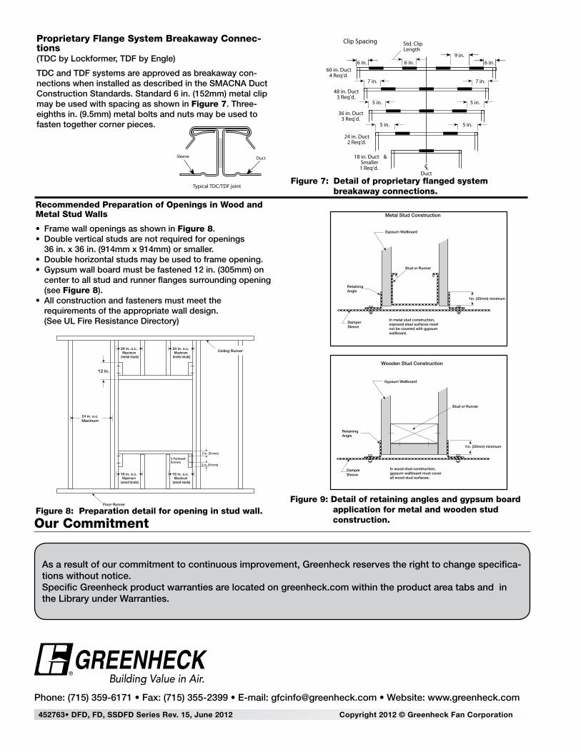
Recommended Preparation of Openings in Wood and Metal Stud Walls
• Frame wall openings as shown in Figure 8.• Double vertical studs are not required for openings
36 in. x 36 in. (914mm x 914mm) or smaller.• Double horizontal studs may be used to frame opening.• Gypsum wall board must be fastened 12 in. (305mm) on
center to all stud and runner flanges surrounding opening (see Figure 8).
• All construction and fasteners must meet the requirements of the appropriate wall design. (See UL Fire Resistance Directory)
Figure 8: Preparation detail for opening in stud wall.Figure 9: Detail of retaining angles and gypsum board
application for metal and wooden stud construction.
Metal Stud Construction
Gypsum Wallboard
Retaining Angle
Stud or Runner
1in. (25mm) minimum
Damper Sleeve
In metal stud construction, exposed steel surfaces need not be covered with gypsumwallboard.
Wooden Stud Construction
Gypsum Wallboard
Stud or Runner
1in. (25mm) minimum
Retaining Angle
Damper Sleeve
In wood stud construction,gypsum wallboard must coverall wood stud surfaces.
DuctSleeve
6 in.
Std. ClipLength
CLDuct
60 in. Duct4 Req’d.
48 in. Duct3 Req’d.
36 in. Duct3 Req’d.
24 in. Duct2 Req’d.
18 in. Duct &Smaller1 Req’d.
Clip Spacing
Typical TDC/TDF joint
6 in. 6 in.9 in.
7 in.7 in.
5 in. 5 in.
5 in.5 in.
Proprietary Flange System Breakaway Connec-tions(TDC by Lockformer, TDF by Engle)
TDC and TDF systems are approved as breakaway con-nections when installed as described in the SMACNA Duct Construction Standards. Standard 6 in. (152mm) metal clip may be used with spacing as shown in Figure 7. Three-eighths in. (9.5mm) metal bolts and nuts may be used to fasten together corner pieces.
Figure 7: Detail of proprietary flanged system breakaway connections.
DuctSleeve
6 in.
Std. ClipLength
CLDuct
60 in. Duct4 Req’d.
48 in. Duct3 Req’d.
36 in. Duct3 Req’d.
24 in. Duct2 Req’d.
18 in. Duct &Smaller1 Req’d.
Clip Spacing
Typical TDC/TDF joint
6 in. 6 in.9 in.
7 in.7 in.
5 in. 5 in.
5 in.5 in.
452763• DFD, FD, SSDFD Series Rev. 15, June 2012 Copyright 2012 © Greenheck Fan Corporation
As a result of our commitment to continuous improvement, Greenheck reserves the right to change specifica-tions without notice.Specific Greenheck product warranties are located on greenheck.com within the product area tabs and in the Library under Warranties.
®
Phone: (715) 359-6171 • Fax: (715) 355-2399 • E-mail: [email protected] • Website: www.greenheck.com
Our Commitment