fdm-fsk - gdi communications aug 06 fdm-fsk preliminary user guide dwg: a01230 fdm series of fiber...
TRANSCRIPT
16 Aug 06 FDM-FSK Preliminary User Guide Dwg: A01230
(TI) 16 August 2006
GDI COMMUNICATIONS LLC PO Box 1330 280 I-80 Exit 1
Verdi, NV 89439
Phone: (775) 345-8000 Fax: (775) 345-8010
Email: [email protected]
FDM-FSK Fiber Optic Modem
With Built in Model 4xx Series
FSK Modem
USER GUIDE
FDM Series All Fiber Topologies - Compliant

16 Aug 06 FDM-FSK Preliminary User Guide Dwg: A01230
FDM Series of Fiber Optic Modems
• Multiple Fiber Topologies in One Modem Single Ring, Dual Redundant Rings, Daisy Chain and Point to Point.
• Combination Fiber Optic and FSK Modems Built in FSK Modems for 2/4 wire Copper and Fiber Applications.
• Intuitive Fiber Status Display
Pictorially indicates the switching status of the modem.
• Fiber Identification
Display shows a 1 or 2 to indicate which port the fiber belongs.
• Generates DTE Handshaking
Necessary for Remote Fiber to 2/4Wire FSK to TMC applications.
• Auxiliary Data Port
For 2/4Wire FSK or SS Radio Branch Circuits.
• Built-in Uninterruptible Power Supply
Provides Optical Continuity at a Failed Intersection.
AUXPORT
RJ45
1 RI
3 DTR2 CD
4 SG
RXD 5 TXD 6CTS 7RTS 8
MODEL FDM170GDI Communications LLC
Verdi NV 89439775-345-8000
IN
OUT
R1T2
T1
R2
MODEM
FIBER STATUS
PWR
FAIL
1 8
ENABLE
DISABLE BAT
TER
Y
AU
X C
ON
N
FDM2SA
GDI Communications
TXD
RXD
Data PortsKOD RTS
Anti-Strm
Reset
T1
R2
R1
T2
LOS
LOS
MainDC Power Center
Battery
Alarm Charging
RING 2
RING 1
R1
R2T2
T1
LOS
LOS
PWR
RING STATUS
MAIN DATA ALARM
RESET
ANTI-STREAM
AUX DATA
SERIAL PORT
TXD RXD
TXD RXD
TXD RXD
FDM
2070-6D
GDINEVADA
Fail
R2
T1
T2
R1
FDM2SA
FDM170
FDM2070
FDM-FiberHub
R1 T2
GDI Communications
TXD
RXD
Link Activity
Data Port Anti- Streaming
TXD
RXD
Alarm Reset
AB CD
D
T1
R2
R1
T2
T1 R2
A B
CLOS
LOS
LOS
LOS
MainDC Power Center
Battery
Alarm Charging
FDM-FiberHub
FDM-FSK
GDI Communications
TXD
RXD
Data PortsKOD RTS
Anti-Strm
Reset
T1
R2
R1
T2
LOS
LOS
MainDC Power Center
Battery
Alarm Charging
CD
RTS
2/4 Wire FSKKOD
CTS
TXD RXD
A B
FDM-FSK
Stand Alone Models Plug-in Models for Controllers and Racks
16 August 06 FDM-FSK Preliminary User Guide 1 Dwg: A01230
FDM -FSK ----- Table of Contents------ Page 1/3
FDM Series Overview 4
The FDM Series 4
FDM170 5 FDM2070 5 FDM-FiberHub 6 FDM2SA 6
Introduction to the FDM-FSK Modem 7
FDM-FSK
Basic Signal Flow Diagram 7 FSK Modem Section 7 Modem Ergonomics 8
Front Panel 8
Fiber Optic Modem Display s 9 Data Port Activity Display 9 TXD LED 9 RXD LED 9 Data Port Anti- Streaming 9 Reset Switch 9 Intuitive Fiber Status Displays 9 Fiber Identification 9 Fiber Status Displays for Redundant Rings and Daisy Chains 10 Fiber Status Displays for Single Rings 10
2/4 Wire LED Displays 11
CD Carrier Detect 11 KOD Key On Data 11 RTS Request To Send 11 CTS Clear To Send 11 TXD Transmit Data 11 RXD Receive Data 11
DC Power Center Display 11
DC Power Center LED Indicators 12 Main 12 Charging 12 Battery 12 Alarm 12
16 August 06 FDM-FSK Preliminary User Guide 2 Dwg: A01230
Rear Panel 12 Power Connections 12 Dual Data Ports 13 Optical Ports 13
Bottom Panel 13 Signal Flow Diagrams 14
Sequence of Events 14 Data Port Flow Diagrams 15
Setting up the Modem 16
Mounting Options 16 Configuring the FDM Modem Section 16
FDM DIP Switches 17
Master/Salve 17 Topology Selections 17 2 Rings (Self Healing Dual Counter Rotating Rings). 17 1 Ring 17 Daisy Chain 17
Data Protocol RS232/422 18 Baud Rates 18 Parity 18 RTS/CTS Handshaking 18 CTS Delay 18 Anti-Streaming 19
Optical Dynamic Range 19
Fiber Identification Techniques 20
Fiber Applications 21 Self Healing Dual Counter Rotating Ring Operation 21 Single Ring Operation 23 Point to Point 25 Point to Point with Redundant Fiber Path 26 Daisy Chain Operation 28 Dual Daisy Chain (Center Master) 30
16 August 06 FDM-FSK Preliminary User Guide 3 Dwg: A01230
Configuring the FSK Modem Section 31
Primer on Frequency Shift Keying Modems 31 Communications Sequence of Events 32
The Pole 32 The Response 33
Front, Rear and Bottom Panels 34
2/4 Wire FSK Display CD 34 RTS 34 CTS 34 TXD 34 RXD 34 KOD 34
Rear Panel 34 Copper FSK 34
Bottom Panel DIP Switches 35
Full Duplex or Half Duplex 35 RTS to CTS Time 35 Carrier Turn Off Time 35 Local Echo 35 Receiver Squelch Time 35 Carrier Detect Time 35 Load Compensation 35
FSK Applications 36 Half Duplex Operation (2 Wire “One Pair”) 36 Full Duplex Operation (4 Wire “2 Pairs”) 37 A Word on Dynamic Range 38
Combined FDM and FSK Applications 39 Fiber to Copper to Fiber --- Copper Bridge Application 40 Copper to Fiber to Copper --- Fiber Bridge Application 40 Fiber with Copper Branch --- Copper Tap Application 41
Factory Default Settings and Pin-Out Diagrams 42 KOD Jumper 43 Care and Handling Procedures for Optical Connectors 44 Disclaimer 47

16 August 06 FDM-FSK Preliminary User Guide 4 Dwg: A01230
FDM SERIES OVERVIEW
The FDM Series of Hardened Modems are designed for polling applications utilizing
RS232/422 Asynchronous transmission over Multimode and Singlemode Fiber Optics. All modems in the series are communications compatible with each other, thus allowing greater flexibility of use. The FDM Series comprise of six Digital Modems:
1. The FDM2SA is a Stand Alone version. 2. The FDM170 is a Plug-in version for the 170 Controller 3. The FDM2070 is a Plug-in version for the 2070 Controller 4. The FDM FiberHub performs as a 1 x 3 star optical hub that ties in
optical branch circuits into the mainstream communications path. 5. The FDM-FSK is a combination of a FDM2SA and a FSK modem. 6. The FDM-SSR is a combination of a FDM2SA and a Spread Spectrum
Radio. The modems can operate in many different topologies, even on a simple fiber ring when there is only one fiber available, later as more fibers become available, simply flip a switch to change to the new topology. This unique capability of operating in multiple topologies offers the advantage of One Modem for all Topologies. Switch Selectable Topologies are as follows:
• Single Fiber Ring • Dual Fiber Redundant Ring (Self Healing) • Point to Point • Daisy Chain Format.
The modems have a high dynamic range yet they are immune to optical over loads, therefore no optical attenuators are required for short runs or even bench top “back to back” testing! Any modem can be designated as a Master or Slave, also for Auto Restoration any modem can be designated as an Auxiliary Master.

16 August 06 FDM-FSK Preliminary User Guide 5 Dwg: A01230
FDM SERIES OVERVIEW continued
A unique and intuitive Dual Seven Segment display graphically indicates the status of the fiber system, making diagnostics visually simple. All FDM series modems have the unique capability of Fiber Identification; the display will flash a 1 or 2 indicating which circuit the fiber belongs to. Other advantages include multiple use Dual Data Ports enabling branch circuit capabilities such as an On Street Master to Local Controller (same location), or 4wire or Spread Spectrum Radio communications. All modems have the unique capability of having their Auxiliary Port switched from DCE to DTE mode. This feature allows the Main port to drive the Aux-Port as well as the fiber, primarily used for Street Master communications with the local controller or driving some other modem. Only FDM optical modems have the unique ability to generate a Carrier Detect both before and after data flow, this is essential when connecting to 2 Wire FSK communications. This Dynamic CD acts like a “DTE’s RTS” and is used to initiate handshaking to a DCE’s RTS input. The FDM Series represents a new generation of digital fiber optic modems utilizing a Replaceable Operating System (ROS). As requirements change, or new features become available, a new program can be loaded so as to provide a migration path to upgrade the existing system.
FDM170
This is a Plug-In version for the 170 Series of Controllers and the R400/R800 Rack Series. The Main Data port is connected via the card edge connector to the 170 backplane while the Aux Data Port RJ45 is front accessible for combining external data links in the polling stream. For rack-mounted communications at the Traffic Maintenance Center, R400/R800 Series Racks can be populated with the FDM170 to complete the communications system.
FDM2070
This is a Plug-In version for the 2070 Series of Controllers. The Main and Auxiliary Data ports provide the same functionality as in the FDM170, plus one of the 2070’s spare Serial Ports SP2 or SP4 (slot dependant) is also brought out to the front panel. For rack-mounted communications at the Traffic Maintenance Center, R400/R800 Series Racks would be populated with the FDM170 to complete the communications system.
16 August 06 FDM-FSK Preliminary User Guide 6 Dwg: A01230
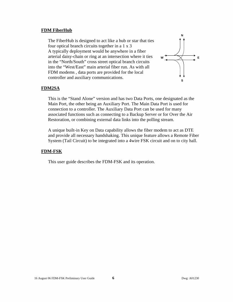
FDM FiberHub The FiberHub is designed to act like a hub or star that ties four optical branch circuits together in a 1 x 3 A typically deployment would be anywhere in a fiber arterial daisy-chain or ring at an intersection where it ties in the “North/South” cross street optical branch circuits into the “West/East” main arterial fiber run. As with all FDM modems , data ports are provided for the local controller and auxiliary communications.
FDM2SA
This is the “Stand Alone” version and has two Data Ports, one designated as the Main Port, the other being an Auxiliary Port. The Main Data Port is used for connection to a controller. The Auxiliary Data Port can be used for many associated functions such as connecting to a Backup Server or for Over the Air Restoration, or combining external data links into the polling stream. A unique built-in Key on Data capability allows the fiber modem to act as DTE and provide all necessary handshaking. This unique feature allows a Remote Fiber System (Tail Circuit) to be integrated into a 4wire FSK circuit and on to city hall.
FDM-FSK
This user guide describes the FDM-FSK and its operation.
N
W E
S
16 August 06 FDM-FSK Preliminary User Guide 7 Dwg: A01230
INTRODUCTION to the FDM-FSK
FDM-FSK
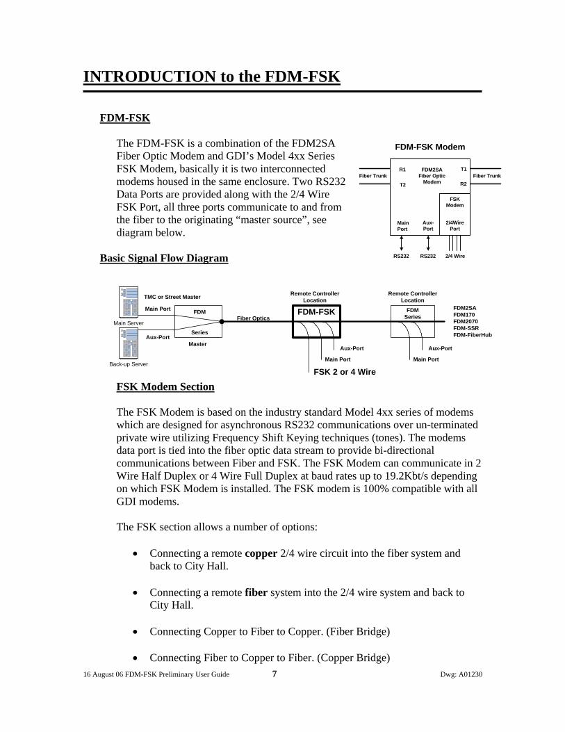
The FDM-FSK is a combination of the FDM2SA Fiber Optic Modem and GDI’s Model 4xx Series FSK Modem, basically it is two interconnected modems housed in the same enclosure. Two RS232 Data Ports are provided along with the 2/4 Wire FSK Port, all three ports communicate to and from the fiber to the originating “master source”, see diagram below.
Basic Signal Flow Diagram
FSK Modem Section The FSK Modem is based on the industry standard Model 4xx series of modems which are designed for asynchronous RS232 communications over un-terminated private wire utilizing Frequency Shift Keying techniques (tones). The modems data port is tied into the fiber optic data stream to provide bi-directional communications between Fiber and FSK. The FSK Modem can communicate in 2 Wire Half Duplex or 4 Wire Full Duplex at baud rates up to 19.2Kbt/s depending on which FSK Modem is installed. The FSK modem is 100% compatible with all GDI modems. The FSK section allows a number of options:
• Connecting a remote copper 2/4 wire circuit into the fiber system and back to City Hall.
• Connecting a remote fiber system into the 2/4 wire system and back to
City Hall.
• Connecting Copper to Fiber to Copper. (Fiber Bridge) • Connecting Fiber to Copper to Fiber. (Copper Bridge)
FDM-FSK FDMSeries
FSK 2 or 4 WireMain Port
Aux-Port
Main Port
Aux-Port
FDMMain PortFiber Optics
Aux-Port
TMC or Street Master Remote ControllerLocation
Remote ControllerLocation
Series
FDM2SAFDM170FDM2070FDM-SSRFDM-FiberHub
Main Server
Back-up Server
Master
Fiber Trunk
MainPort
Aux-Port
T1
R2T2
R1
2/4WirePort
Fiber Trunk
RS232 RS232 2/4 Wire
FSKModem
FDM2SAFiber Optic
Modem
FDM-FSK Modem
16 August 06 FDM-FSK Preliminary User Guide 8 Dwg: A01230
Modem Ergonomics The Front Panel displays information on the status of the FDM-FSK. The Rear Panel is where all the connections are made to the modem and the switch-able options are located on the Bottom Panel to minimize ingress of foreign material in road side cabinet applications. On the Rear Panel, there are two dual bulkhead Fiber Ports which can be easily changed between ST, FC and SC style connectors; so can the internal mini patchcords located between the bulkheads and the optical transceivers. These inexpensive patchcords act like a “fusible link” and provide the transceivers with 100% protection from being damaged by external dirty patchcords. Replacing the patchcords can be easily done by the customer. Two Data Ports, Main and Auxiliary are provided, the Main Data Port DB9 typically connects to the local controller while the Auxiliary RJ45 connector can be used to bring in radio based communications into the main data stream. The FSK Port can operate in 2 or 4 wire mode (Half/ Full Duplex) and is 100% compatible with all GDI FSK Modems The FDM-FSK has three mounting options, left or right wall mounting via a pair of “Keyhole” slots on both sides, or as a Stand Alone shelf mounted unit while still maintaining a vertical front panel view for all three options. The FDM-FSK has an optional internal Uninterrupted Power Supply “UPS” that maintains full modem operation without any loss of communications.
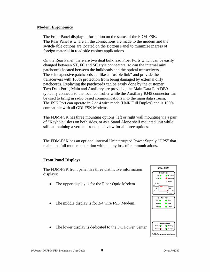
Front Panel Displays The FDM-FSK front panel has three distinctive information displays:
• The upper display is for the Fiber Optic Modem. • The middle display is for 2/4 wire FSK Modem.
• The lower display is dedicated to the DC Power Center
FDM-FSK
GDI Communications
TXD
RXD
Data PortsKOD RTS
Anti-Strm
Reset
T1
R2
R1
T2
LOS
LOS
MainDC Power Center
Battery
Alarm Charging
CD
RTS
2/4 Wire FSKKOD
CTS
TXD RXD
BA
16 August 06 FDM-FSK Preliminary User Guide 9 Dwg: A01230
Fiber Optic Modem Displays
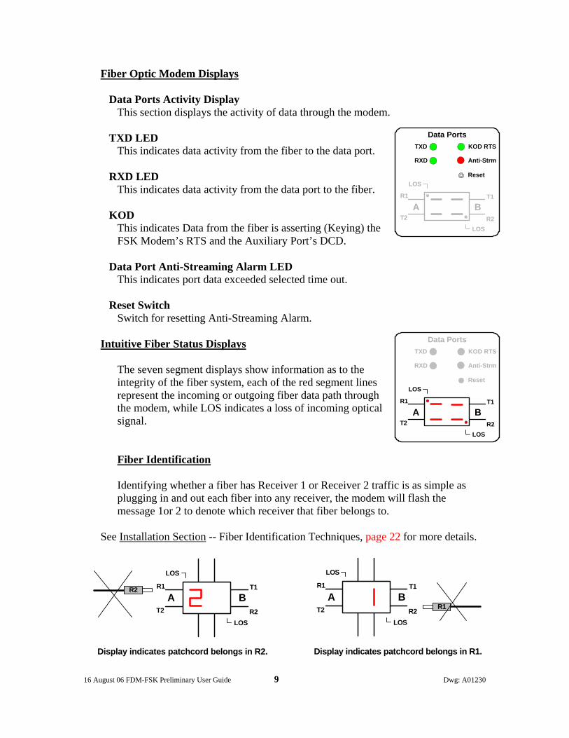
Data Ports Activity Display This section displays the activity of data through the modem.
TXD LED This indicates data activity from the fiber to the data port.
RXD LED This indicates data activity from the data port to the fiber.
KOD
This indicates Data from the fiber is asserting (Keying) the FSK Modem’s RTS and the Auxiliary Port’s DCD.
Data Port Anti-Streaming Alarm LED This indicates port data exceeded selected time out.
Reset Switch Switch for resetting Anti-Streaming Alarm.
Intuitive Fiber Status Displays
The seven segment displays show information as to the integrity of the fiber system, each of the red segment lines represent the incoming or outgoing fiber data path through the modem, while LOS indicates a loss of incoming optical signal.
Fiber Identification Identifying whether a fiber has Receiver 1 or Receiver 2 traffic is as simple as plugging in and out each fiber into any receiver, the modem will flash the message 1or 2 to denote which receiver that fiber belongs to.
See Installation Section -- Fiber Identification Techniques, page 22 for more details.
T1
R2
R1
T2A B
LOS
LOS
R2
Display indicates patchcord belongs in R2.
T1
R2
R1
T2A B
LOS
LOS
R1
Display indicates patchcord belongs in R1.
TXD
RXD
Data PortsKOD RTS
Anti-Strm
Reset
T1
R2
R1
T2
LOS
LOS
A B
TXD
RXD
Data PortsKOD RTS
Anti-Strm
Reset
T1
R2
R1
T2
LOS
LOS
A B
16 August 06 FDM-FSK Preliminary User Guide 10 Dwg: A01230
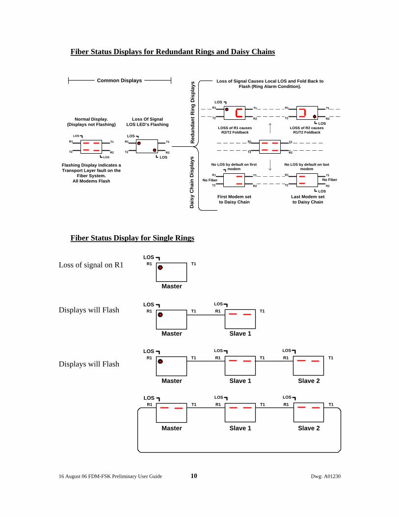
Fiber Status Displays for Redundant Rings and Daisy Chains
Fiber Status Display for Single Rings
Loss of signal on R1 Displays will Flash Displays will Flash
T1R1LOS
T1R1LOS
T1R1LOS
T1R1LOS
T1R1
LOS
T1R1LOS
T1R1LOS
T1R1
LOS
T1R1LOS
Master
Master
Master
Master
Slave 1
Slave 1 Slave 2
Slave 1 Slave 2
T1
R2
R1
T2
LOS
LOS
Red
unda
nt R
ing
Dis
play
sCommon Displays
Dai
sy C
hain
Dis
play
s
Loss of Signal Causes Local LOS and Fold Back toFlash (Ring Alarm Condition).
Normal Display.(Displays not Flashing)
T1
R2
R1
T2
LOS
LOS
T1
R2
R1
T2
T1
R2
R1
T2
T1
R2
R1
T2
Loss Of SignalLOS LED’s Flashing
LOS
LOSS of R1 causesR2/T2 Foldback
First Modem setto Daisy Chain
Last Modem setto Daisy Chain
T1
R2
R1
T2
T1
R2
R1
T2
LOSLOSS of R2 causes
R1/T2 Foldback
No LOS by default on firstmodem
No Fiber No Fiber
LOS
No LOS by default on lastmodem
Flashing Display indicates aTransport Layer fault on the
Fiber System.All Modems Flash

16 August 06 FDM-FSK Preliminary User Guide 11 Dwg: A01230
2/4 Wire FSK Display
This section displays the activity of data through the FSK Modem.
CD LED This indicates the modem has detected a carrier tone from a remote modem on the 2/4 Wire circuit.
KOD This indicates Data from the fiber is asserting (Keying) the FSK Modem’s RTS.
RTS LED
This indicates the Fiber Optic modem has asserted RTS to the FSK modem.
CTS LED This indicates the FSK modem has asserted CTS to the Fiber Optic Modem.
TXD LED
This indicates data is being transmitted from the Fiber Optic modem to the FSK Modem.
RXD LED This indicates data is being received from the FSK Modems 2/4 Wire circuits
DC Power Center Display The DC Power Center shows the power state of the FiberHub.
The DC Power Center provides information on the status of the optional internal Uninterrupted Power Supply (UPS), such as incoming Main power, battery Charging (full and trickle charge), Alarm (no external power) and Battery power only. If the modem is equipped with an optional internal UPS and power fails, the supported modem(s) will be fully operational until the batteries are depleted. Resumption of power will start the battery charging process while at the same time the modem will be fully operational. If the installation site supports a 24VDC UPS this may be connected to the DC power connector on the modem in lieu of an internal UPS.
MainDC Power Center
Battery
Alarm Charging
Normal Condition
Running on Main Power andcharging the batteries
MainDC Power Center
Battery
Alarm Charging
Incoming Power Failure
Running on Battery Power withan Alarm indication.
CD
RTS
2/4 Wire FSKKOD
CTS
TXD RXD
16 August 06 FDM-FSK Preliminary User Guide 12 Dwg: A01230
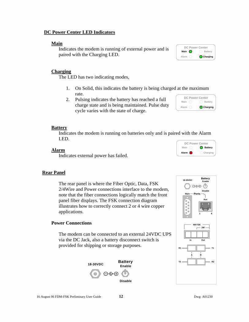
DC Power Center LED Indicators
Main Indicates the modem is running of external power and is paired with the Charging LED.
Charging
The LED has two indicating modes,
1. On Solid, this indicates the battery is being charged at the maximum rate.
2. Pulsing indicates the battery has reached a full charge state and is being maintained. Pulse duty cycle varies with the state of charge.
Battery
Indicates the modem is running on batteries only and is paired with the Alarm LED.
Alarm Indicates external power has failed.
Rear Panel
The rear panel is where the Fiber Optic, Data, FSK 2/4Wire and Power connections interface to the modem, note that the fiber connections logically match the front panel fiber displays. The FSK connection diagram illustrates how to correctly connect 2 or 4 wire copper applications.
Power Connections
The modem can be connected to an external 24VDC UPS via the DC Jack, also a battery disconnect switch is provided for shipping or storage purposes.
BatteryEnable
Disable
18-30VDC
MainDC Power Center
Battery
Alarm Charging
MainDC Power Center
Battery
Alarm Charging
MainDC Power Center
Battery
Alarm Charging
T2
R1
R2
T1
18-30VDCBattery
Enable
Disable
1 8
Main
Aux
Ports
1 8
4W FSK2W
In Out
A B
16 August 06 FDM-FSK Preliminary User Guide 13 Dwg: A01230
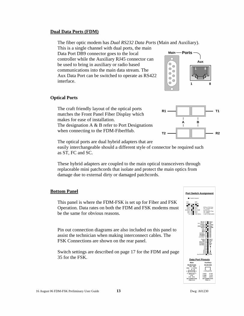
Dual Data Ports (FDM)
The fiber optic modem has Dual RS232 Data Ports (Main and Auxiliary). This is a single channel with dual ports, the main Data Port DB9 connector goes to the local controller while the Auxiliary RJ45 connector can be used to bring in auxiliary or radio based communications into the main data stream. The Aux Data Port can be switched to operate as RS422 interface.
Optical Ports
The craft friendly layout of the optical ports matches the Front Panel Fiber Display which makes for ease of installation. The designation A & B refer to Port Designations when connecting to the FDM-FiberHub. The optical ports are dual hybrid adapters that are easily interchangeable should a different style of connector be required such as ST, FC and SC. These hybrid adapters are coupled to the main optical transceivers through replaceable mini patchcords that isolate and protect the main optics from damage due to external dirty or damaged patchcords.
Bottom Panel This panel is where the FDM-FSK is set up for Fiber and FSK Operation. Data rates on both the FDM and FSK modems must be the same for obvious reasons.
Pin out connection diagrams are also included on this panel to assist the technician when making interconnect cables. The FSK Connections are shown on the rear panel. Switch settings are described on page 17 for the FDM and page 35 for the FSK.
1 8
Main
Aux
Ports
1 8
T2
R1
R2
T1
A B
SlaveOff1 RingRingRS485OffOffOffOffOffOffOff
Parity NoneOdd Even
RTS-CTS OffCTS-0ms 8msAnt-Strm Off
248
1832 64 Off
Aux.Port DCE DTE
MasterAux. Master
2 RingsDaisy Chain
RS232120024009600
19.2Kbts38.4Kbts57.6Kbts
115.2Kbts
Port Switch Assignment
Data Port Pinouts
RS-232 RJ45
Auxiliary
1 8
2 DCD4 GND5 RXD
6 TXD7 CTS8 RTS
NO CONNECTIONPINS 1-3
DCDRXDTXD
GND
CTS RTSNO CONNECTION
PINS 4-6-9
MainRS-232 Female
15
69
FullDuplex
12ms 6ms10ms 5ms
(Full) Off On (Half)6ms 3ms8ms 4ms
Hi 600 Ohms
Switch Actuator
HalfDuplex
RTS to CTS TimeCxr. Turnoff TimeLocal EchoRcr. Squelch TimeCxr. DetectLoad Compensation

16 August 06 FDM-FSK Preliminary User Guide 14 Dwg: A01230
Signal Flow Diagrams
Sequence of Events
• The Polling Data enters the Masters Main or Auxiliary Port and is then broadcast
to the remote modems over the fiber optics. • At each Remote FDM the Polling Data is past to the Main, Auxiliary and if
equipped, the FSK Ports. • Response Data entering the Remotes Main, Auxiliary and FSK Ports is
transmitted back to the Master Modem. • At the Master Modem, Response Data from the Remotes is passed to the Masters
Main and Auxiliary Ports and back to the Servers.
FDM-FSK FDMSeries
FSK 2 or 4 WireMain Port
Aux-Port
Main Port
Aux-Port
FDMMain PortFiber Optics
Aux-Port
TMC or Street Master Remote ControllerLocation
Remote ControllerLocation
Series
FDM2SAFDM170FDM2070FDM-SSRFDM-FiberHub
Main Server
Back-up Server

16 August 06 FDM-FSK Preliminary User Guide 15 Dwg: A01230
Data Port Flow Diagrams
1. Normal Operation at a Controller Location. (Aux Port switched to Normal Mode DCE)
This dual ports allows the Main Port to be connected to Local Controller, while the Auxiliary Port can be connected to another modem such as a Spread Spectrum Radio (DCE), while the FSK port drives the 2 or 4Wire system.
Mounting Options The modem has several versatile mounting options, it can be shelf mounted as a Stand Alone, or hang on a cabinet wall utilizing a pair of “Keyhole” slots. Both sides have pairs of keyhole slots for left or right wall mounting so as to maintain the desired front or rear panel view, hole centers are at 7.5inches.
DTEAux.Port DCE
AB Fiber
LinesData Flow
3 TXD
6 TXD
2 RXD
5 RXD
7 RTS
8 RTS
8 CTS
7 CTS
Main Port (DB9F)
Aux Port (RJ45)
LocalController
(DTE)
SpreadSpectrum
Radio
IFC-AXXXXX
IFC-AXXXXX
Com
mon
Func
tion
FDM-FSK DCE Operation
Data PortsFiber Optics
FDM
1 DCD
2 KODRTS
+ 5V
In
Out
FSKData Flow
KODRTS (DCD)
2W4Wire
FDM Data Ports
FSK Audio
To Master viaFiber Optics
FSKRemoteModems
16 August 06 FDM-FSK Preliminary User Guide 16 Dwg: A01230
Setting up the Modem
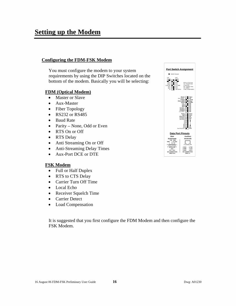
Configuring the FDM-FSK Modem
You must configure the modem to your system requirements by using the DIP Switches located on the bottom of the modem. Basically you will be selecting:
FDM (Optical Modem) • Master or Slave • Aux-Master • Fiber Topology • RS232 or RS485 • Baud Rate • Parity – None, Odd or Even • RTS On or Off • RTS Delay • Anti Streaming On or Off • Anti-Streaming Delay Times • Aux-Port DCE or DTE
FSK Modem • Full or Half Duplex • RTS to CTS Delay • Carrier Turn Off Time • Local Echo • Receiver Squelch Time • Carrier Detect • Load Compensation It is suggested that you first configure the FDM Modem and then configure the FSK Modem.
SlaveOff1 RingRingRS485OffOffOffOffOffOffOff
Parity NoneOdd Even
RTS-CTS OffCTS-0ms 8msAnt-Strm Off
248
1832 64 Off
Aux.Port DCE DTE
MasterAux. Master
2 RingsDaisy Chain
RS232120024009600
19.2Kbts38.4Kbts57.6Kbts
115.2Kbts
Port Switch Assignment
Data Port Pinouts
RS-232 RJ45
Auxiliary
1 8
2 DCD4 GND5 RXD
6 TXD7 CTS8 RTS
NO CONNECTIONPINS 1-3
DCDRXDTXD
GND
CTS RTSNO CONNECTION
PINS 4-6-9
MainRS-232 Female
15
69
FullDuplex
12ms 6ms10ms 5ms
(Full) Off On (Half)6ms 3ms8ms 4ms
Hi 600 Ohms
Switch Actuator
HalfDuplex
RTS to CTS TimeCxr. Turnoff TimeLocal EchoRcr. Squelch TimeCxr. DetectLoad Compensation
16 August 06 FDM-FSK Preliminary User Guide 17 Dwg: A01230
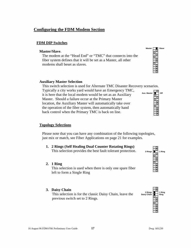
Configuring the FDM Modem Section
FDM DIP Switches
Master/Slave. The modem at the “Head End” or “TMC” that connects into the fiber system defines that it will be set as a Master, all other modems shall beset as slaves.
Auxiliary Master Selection
This switch selection is used for Alternate TMC Disaster Recovery scenarios. Typically a city works yard would have an Emergency TMC, it is here that the local modem would be set as an Auxiliary Master. Should a failure occur at the Primary Master location, the Auxiliary Master will automatically take over the operation of the fiber system, then automatically hand back control when the Primary TMC is back on line.
Topology Selections Please note that you can have any combination of the following topologies, just mix or match, see Fiber Applications on page 21 for examples.
1. 2 Rings (Self Healing Dual Counter Rotating Rings) This selection provides the best fault tolerant protection.
2. 1 Ring
This selection is used when there is only one spare fiber left to form a Single Ring
3. Daisy Chain This selection is for the classic Daisy Chain, leave the previous switch set to 2 Rings.
1 Ring2 Rings
1 RingRing
2 RingsDaisy Chain
SlaveMaster
OffAux. Master

16 August 06 FDM-FSK Preliminary User Guide 18 Dwg: A01230
Data Protocol RS232/422
Select RS232 when connecting to traffic controller or other devices utilizing a RS232 port. RS422 is used to drive longer distances than RS232 over 2 pairs of balanced transmission lines .
Baud Rates
The selectable Baud Rates are, 1200, 2400, 9600, 19.2Kbt/s, 38.4Kbt/s, 57.6Kbt/s and 115.2Kbt/s.
Parity
Parity can be set for None, Odd or Even. Switch settings shown are Parity enabled and Even selected. For no Parity select None.
RTS/CTS Handshaking
When Handshaking is turned Off, data arriving at either data port from the attached devices will be transmitted over the fiber. When Handshaking is turned On and RTS is high or raised, data arriving at either data port from the attached devices will be transmitted over the fiber. When RTS is low no data will flow
CTS Delay
The RTS to CTS delay can be set at 0ms or 8ms, 0ms is for fast operation and 8 ms is used for external transmission systems that require a delay.
OffOffOffOffOffOffOff
24009600
38.4Kbts57.6Kbts
1200
19.2Kbts
115.2Kbts
Parity NoneOdd Even
RTS-CTS Off
CTS-0ms 8ms
RS422RS232

16 August 06 FDM-FSK Preliminary User Guide 19 Dwg: A01230
Anti- Streaming Anti-Streaming times 2, 4, 8, 16, 32, and 64 seconds, all are switch selectable and are additive to a maximum of 126 seconds.
When RTS is raised the anti-streaming countdown timer starts, at its conclusion the data to fiber path is inhibited and latched in an open state, CTS is then lowered and the anti-streaming Alarm LED is lit.
Should RTS be lowered the system will automatically reset but the anti-streaming alarm will remain lit indicating data timing violations from the attached controller. If the front panel anti- streaming RESET switch is momentary pushed, the system will automatically reset and the alarm LED will extinguish.
Auxiliary Port DCE/DTE Options
The FDM-FSK is primarily designed for Slave applications, therefore this selection is left in the DCE mode.
Optical Dynamic Range
For any system to work reliably there must be adequate signal level at the receiver. The modem must have a larger Dynamic Range, expressed in db, than the cables end to end attenuation (db). All Singlemode FDM series have 25DB of dynamic range.
Steps necessary to determine reliable operation,
1. Determine if your fiber is Multi-Mode or Single Mode. 2. Using an Optical Power Meter measure the End to End Attenuation of
your fiber pair, including all patchcords at the operating wavelength. 3. Add a minimum of 3db safety margin to this figure. 4. The Dynamic Range must be larger than the overall attenuation obtained
in step 3 for reliable operation.
Mode Operating Wavelength Dynamic Range Model # Singlemode 1300nm SM Laser 25db FDM Series
Ant-Strm Off248
1832
C-Mast 64 Off
DTEAux.Port DCE

16 August 06 FDM-FSK Preliminary User Guide 20 Dwg: A01230
Fiber Identification Techniques This method assumes the technician is dealing with the worst case i.e. no fibers are assigned or labeled at each modem location, just patchcords. Let’s assume that we are installing a Daisy Chain down an arterial roadway, at each end of the system you will have only two fibers, at all locations in between there will be four fibers, two from downstream and two from upstream, all modems are powered off.
1. Starting at the Master location (City Hall) power up the modem and connect the two fibers into T1 and R2.
2. At the next location power up the modem and connect each patchcord, one at time, into R2. When the modems display indicates “1”, insert this fiber into R1.
3. The remaining three patchcords are then rotated through T2 until you see the:
a. Daisy Chain display,
b. Or if you have the Slave set to 2 Rings you will
see a Fold-Back display.
You will now have Fiber communications with City Hall Note: City Hall will also have the Daisy Chain Display, if it was set to 2
Rings then it will have a Fold-Back display.
4. Continue steps 2 and 3 until you reach the end of the Daisy Chain.
T1
R2
R1
T2
LOS
LOS
Slave 1
T1
R2
R1
T2
LOS
LOS
Slave 1
T1
R2
R1
T2
LOS
LOS
Slave 1
T1
R2
R1
T2
LOS
LOS
Master
T1
R2
R1
T2
LOS
LOS
Master
T1
R2
R1
T2
LOS
LOS

16 August 06 FDM-FSK Preliminary User Guide 21 Dwg: A01230
Fiber Applications
Self Healing Dual Counter Rotating Ring Operation
This format requires that two fibers to be connected from modem to modem until a dual counter-rotating ring is formed. The advantage of this format is that if there is a fiber cut between any modems or a modem failure, the adjacent modems straddling the malfunction will automatically fold back into Ring 2 causing the system to self heal by forming a new ring. See Foldback illustration on the next page.
Modem DIP Switch Settings for 9600 8N1
The Dip Switch settings listed below show what would be required to set the modems to operate at 9600baud 8N1, this is a typical setting for the traffic industry, all other switch positions not shown are in the Off position or “other selection”.
Master Modem Slave Modem
Master Slave 2 Rings 2 Rings RS232 RS232 9600 9600 None (Parity) None (Parity) RTS/CTS RTS/CTS CTS-0ms CTS-0ms Off Anti-Stream 2 Seconds Aux Port Normal Aux Port Modem
R1
T1
T1
T1
T1
R1
R1
R1
FDM Slave 1
FDM Slave 2
FDM Slave 3
TMC Computer
RTU / Controller
Dual Counter Rotating Ring
Format
RTU / Controller
RTU / Controller
FDM Master
R2
R2
R2 T2
T2
T2
T2
R2
RING 1
RING 2
16 August 06 FDM-FSK Preliminary User Guide 22 Dwg: A01230
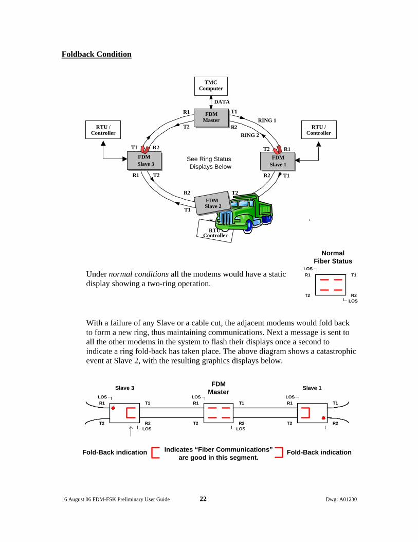
Foldback Condition
Under normal conditions all the modems would have a static display showing a two-ring operation.
With a failure of any Slave or a cable cut, the adjacent modems would fold back to form a new ring, thus maintaining communications. Next a message is sent to all the other modems in the system to flash their displays once a second to indicate a ring fold-back has taken place. The above diagram shows a catastrophic event at Slave 2, with the resulting graphics displays below.
R1
T1
T1
T1
T1
R1
R1
R1
FDMSlave 1
FDM Slave 3
DATA
See Ring StatusDisplays Below
R2
R2
R2 T2
T2
T2
T2
R2
RING 1
RING 2RTU /
Controller RTU /
Controller
TMCComputer
FDM Master
RTU /Controller
FDMSlave 2
T1
R2
R1
T2
LOS
LOS
NormalFiber Status
T1
R2
R1
T2
LOS
LOS
Slave 3
T1
R2
R1
T2
LOS
LOS
T1
R2
R1
T2
LOS
FDMMaster Slave 1
Fold-Back indication Indicates “Fiber Communications”are good in this segment.
Fold-Back indication

16 August 06 FDM-FSK Preliminary User Guide 23 Dwg: A01230
R1
T1
T1
T1
T1
R1
R1
R1
FDM Slave 1
FDM Slave 2
FDM Slave 3
TMC Computer
DATA
RTU / Controller
Single Fiber Loop
RTU / Controller
RTU / Controller
FDM Master
Single Ring Operation
This configuration is useful when there is only one fiber available from modem to modem, it has the lowest security of all configurable systems, should the ring be broken then the system will collapse.
Modem DIP Switch Settings for 9600 8N1 The Dip Switch settings listed below show what would be required to set the modems to operate at 9600baud 8N1, this is a typical setting for the traffic industry, all other switch positions not shown are in the Off position or “other selection”.
Master Modem Slave Modem
Master Slave 1 Ring 1 Ring RS232 RS232 9600 9600 None None RTS/CTS RTS/CTS CTS-0ms CTS-0ms Off Anti-Stream 2 Seconds Aux Port Normal Aux Port Normal
16 August 06 FDM-FSK Preliminary User Guide 24 Dwg: A01230
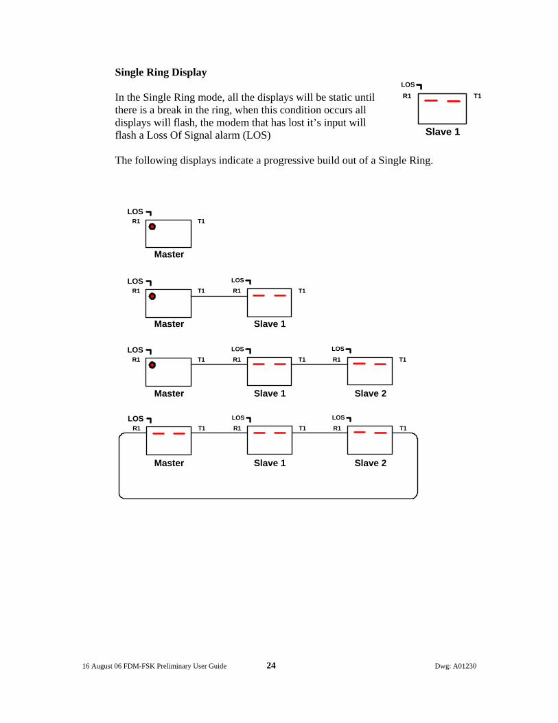
Single Ring Display
In the Single Ring mode, all the displays will be static until there is a break in the ring, when this condition occurs all displays will flash, the modem that has lost it’s input will flash a Loss Of Signal alarm (LOS) The following displays indicate a progressive build out of a Single Ring.
T1R1LOS
T1R1LOS
T1R1LOS
T1R1LOS
T1R1
LOS
T1R1LOS
T1R1LOS
T1R1
LOS
T1R1LOS
Master
Master
Master
Master
Slave 1
Slave 1 Slave 2
Slave 1 Slave 2
T1R1LOS
Slave 1
16 August 06 FDM-FSK Preliminary User Guide 25 Dwg: A01230
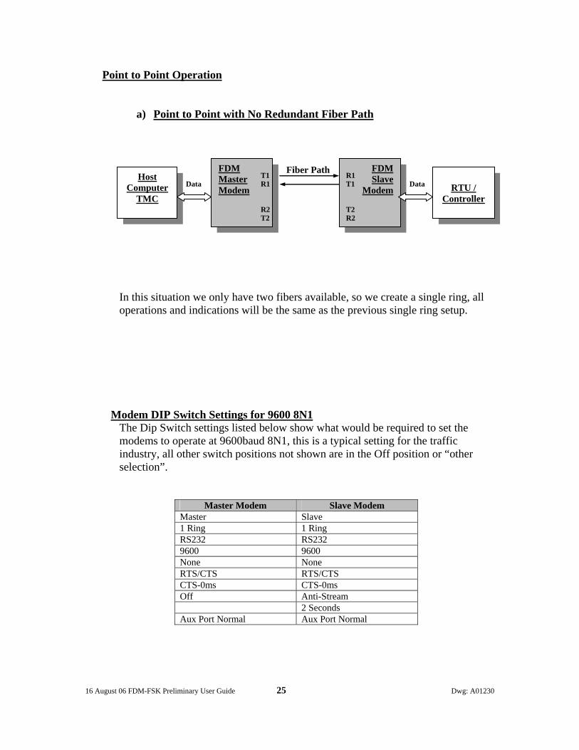
Point to Point Operation
a) Point to Point with No Redundant Fiber Path
In this situation we only have two fibers available, so we create a single ring, all operations and indications will be the same as the previous single ring setup.
Modem DIP Switch Settings for 9600 8N1 The Dip Switch settings listed below show what would be required to set the modems to operate at 9600baud 8N1, this is a typical setting for the traffic industry, all other switch positions not shown are in the Off position or “other selection”.
Master Modem Slave Modem
Master Slave 1 Ring 1 Ring RS232 RS232 9600 9600 None None RTS/CTS RTS/CTS CTS-0ms CTS-0ms Off Anti-Stream 2 Seconds Aux Port Normal Aux Port Normal
FDM Master Modem
FDM Slave
Modem Host
Computer TMC
RTU /
Controller
T1
T2 R2
R1 T1 R1
T2 R2
Data Data
Fiber Path

16 August 06 FDM-FSK Preliminary User Guide 26 Dwg: A01230
b) Point to Point with Redundant Fiber Path
The above shows a single Point to Point System with fail safe redundant fiber optics, if the primary path fails then the system will automatically run on the secondary (redundant) path. The best system security is obtained by running two separate cables following different paths, one cable has T1/R2 fibers and the other has R1/T2, if one cable is completely severed the system will automatically recover via the other cable.
Modem DIP Switch Settings for 9600 8N1
The Dip Switch settings listed below show what would be required to set the modems to operate at 9600baud 8N1, this is a typical setting for the traffic industry, all other switch positions not shown are in the Off position or “other selection”.
Master Modem Slave Modem Master Slave 2 Ring 2 Ring RS232 RS232 9600 9600 None None RTS/CTS RTS/CTS CTS-0ms CTS-0ms Off Anti-Stream 2 Seconds Aux Port Normal Aux Port Normal
FDM Master Modem
FDM Slave
Modem Host
Computer TMC
RTU /
Controller
T1
R2 T2
R1 T2 R2
R1 T1 Cable 2
Data Data
Cable 1
Fiber
T1
R2
R1
T2
LOS
LOS
Fiber Status
Normal
T1
R2
R1
T2
LOS
LOS
Fiber Status
Normal
16 August 06 FDM-FSK Preliminary User Guide 27 Dwg: A01230
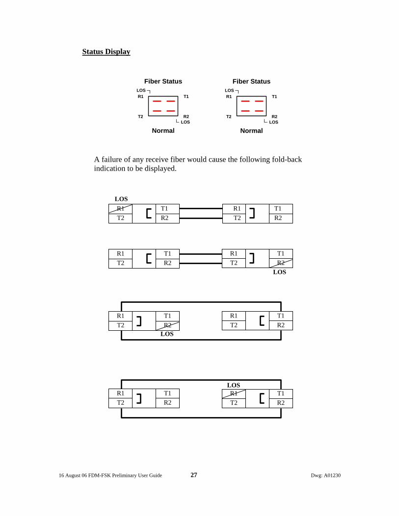
Status Display
A failure of any receive fiber would cause the following fold-back indication to be displayed.
T2 T1R2
R1
T2 T1R2
R1 T2
T1 R2
R1
T2T1 R2
R1
T2 T1R2
R1 T2
T1 R2
R1
T2 T1R2
R1 T2
T1 R2
R1
LOS
LOS
LOS
LOS
T1
R2
R1
T2
LOS
LOS
Fiber Status
Normal
T1
R2
R1
T2
LOS
LOS
Fiber Status
Normal

16 August 06 FDM-FSK Preliminary User Guide 28 Dwg: A01230
Daisy Chain Operation
a) Single String Daisy Chain
This configuration is used when there is no fiber ring available, only one pair of fibers available from controller to controller, a typical application would be a TMC feeding an arterial string and terminating at the far end. Note: This configuration has no redundant path, any failure along the string will
cut off all down stream communications past the point of failure.
Modem DIP Switch Settings for 9600 8N1 The Dip Switch settings listed below show what would be required to set the modems to operate at 9600baud 8N1, this is a typical setting for the traffic industry, all other switch positions not shown are in the Off position or “other selection”. Note:
• Anti-Streaming is “always off” at a Master, optional for all Slave Modems.
Master Modem Middle Slaves End Slave
Master Slave Slave Slave 2 Ring 2 Ring 2 Ring 2 Ring Daisy Chain * Ring Ring Daisy Chain * RS232 RS232 RS232 RS232 9600 9600 9600 9600 None None None None RTS/CTS RTS/CTS RTS/CTS RTS/CTS CTS-0ms CTS-0ms CTS-0ms CTS-0ms Off Anti-Stream Anti-Stream Anti-Stream N.A. 2 Seconds 2 Seconds 2 Seconds Aux Port Normal Aux Port Normal Aux Port Normal Aux Port Normal
T1 FDM
Master
R2
TMC Computer
DATA R1
FDM Slave 1
RTU / Controller
T1
R2 T2
RTU / Controller
FDM Slave 2
FDM Slave 3
RTU / Controller
T1 R1 R1
R2 T2 T2
16 August 06 FDM-FSK Preliminary User Guide 29 Dwg: A01230
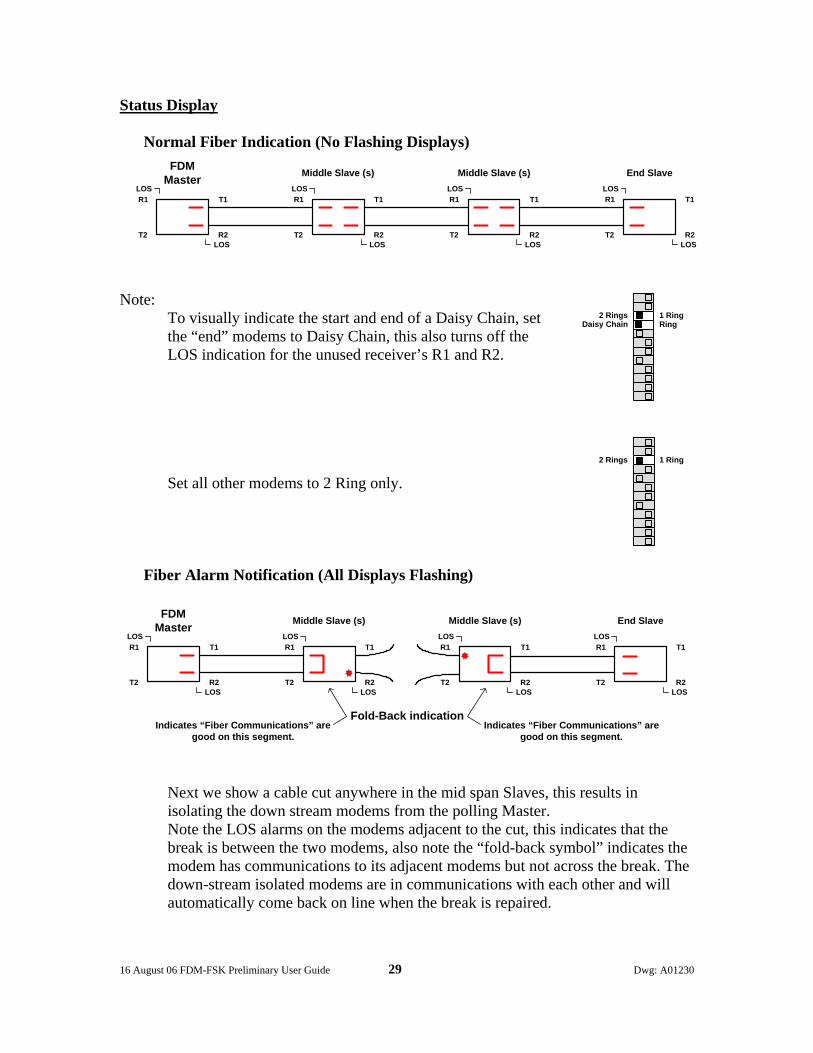
Status Display
Normal Fiber Indication (No Flashing Displays)
Note: To visually indicate the start and end of a Daisy Chain, set the “end” modems to Daisy Chain, this also turns off the LOS indication for the unused receiver’s R1 and R2. Set all other modems to 2 Ring only.
Fiber Alarm Notification (All Displays Flashing)
Next we show a cable cut anywhere in the mid span Slaves, this results in isolating the down stream modems from the polling Master. Note the LOS alarms on the modems adjacent to the cut, this indicates that the break is between the two modems, also note the “fold-back symbol” indicates the modem has communications to its adjacent modems but not across the break. The down-stream isolated modems are in communications with each other and will automatically come back on line when the break is repaired.
T1
R2
R1
T2
LOS
LOS
Middle Slave (s)
T1
R2
R1
T2
LOS
LOS
T1
R2
R1
T2
LOS
LOS
End Slave
T1
R2
R1
T2
LOS
LOS
FDMMaster Middle Slave (s)
1 RingRing
2 RingsDaisy Chain
1 Ring2 Rings
T1
R2
R1
T2
LOS
LOS
Middle Slave (s)
T1
R2
R1
T2
LOS
LOS
T1
R2
R1
T2
LOS
LOS
End Slave
T1
R2
R1
T2
LOS
LOS
FDMMaster Middle Slave (s)
Indicates “Fiber Communications” aregood on this segment.
Fold-Back indicationIndicates “Fiber Communications” are
good on this segment.
16 August 06 FDM-FSK Preliminary User Guide 30 Dwg: A01230
T1 R1 End Slave
RTU / Controller
Master Middle Slave(s)
End Slave
RTU / Controller
RTU / Controller
T1 T1 R1 R1
R2 R2 R2 T2 T2 T2
TMC Computer
DATA
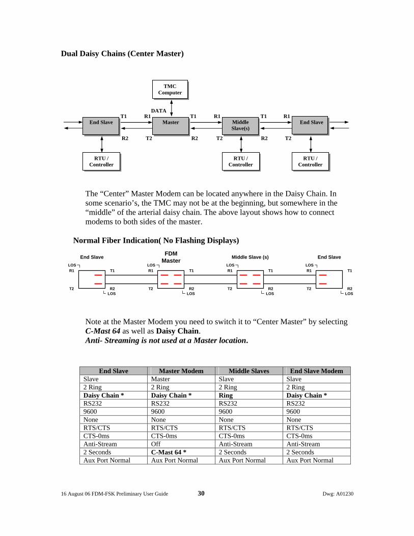
Dual Daisy Chains (Center Master)
The “Center” Master Modem can be located anywhere in the Daisy Chain. In some scenario’s, the TMC may not be at the beginning, but somewhere in the “middle” of the arterial daisy chain. The above layout shows how to connect modems to both sides of the master.
Normal Fiber Indication( No Flashing Displays)
Note at the Master Modem you need to switch it to “Center Master” by selecting C-Mast 64 as well as Daisy Chain. Anti- Streaming is not used at a Master location.
End Slave Master Modem Middle Slaves End Slave Modem Slave Master Slave Slave 2 Ring 2 Ring 2 Ring 2 Ring Daisy Chain * Daisy Chain * Ring Daisy Chain * RS232 RS232 RS232 RS232 9600 9600 9600 9600 None None None None RTS/CTS RTS/CTS RTS/CTS RTS/CTS CTS-0ms CTS-0ms CTS-0ms CTS-0ms Anti-Stream Off Anti-Stream Anti-Stream 2 Seconds C-Mast 64 * 2 Seconds 2 Seconds Aux Port Normal Aux Port Normal Aux Port Normal Aux Port Normal
T1
R2
R1
T2
LOS
LOS
Middle Slave (s)
T1
R2
R1
T2
LOS
LOS
T1
R2
R1
T2
LOS
LOS
End Slave
T1
R2
R1
T2
LOS
LOS
FDMMasterEnd Slave

16 August 06 FDM-FSK Preliminary User Guide 31 Dwg: A01230
Configuring the FSK Modem Section
First a Primer on Frequency Shift Keying Modems The term Modem is a combination of two words, Modulator and Demodulator. Modem Frequency Shift Keying (FSK) Modems are designed to convert digital data to tone frequencies, this process is called modulation. The frequencies can easily be transmitted via a communication line to the receiving modem. At the opposite end of the communication line the tone frequencies are converted back to digital data by a process known as demodulation. By using this mechanism, two digital devices, such as Traffic Maintenance Center’s (TMC) Computer and a Remote Controller can communicate with each other via the outside cable plant. The 4xx series of modems use a modulation technique known as Frequency Shift Keying (FSK). Digital information is binary in format: that is, data is represented by either logic high or logic low (1 or 0). Communications terminology refers to logic Low as Mark and logic High as a Space. FSK Modems utilize this fact and generate a unique frequency for each logic level. Each model in the 4xx series have their own unique set of frequencies due to the baud rate therefore only modems of the same model number can communicate with each other, see the following chart. The rate at which the communication line changes state is known as the baud rate, this can be interpreted to be equivalent of bits per second. The 4xx Series of Modems are capable of communicating at baud rates up to 19200Kbts depending on the model.
Model # RS232 Input/Output 400 496 419
Baud Rate 1200 9600 19200 Mark Frequency Low (0) 1200Hz 11200Hz 19200Hz Space Frequency High (1) 2200Hz 17600Hz 38400Hz Soft Carrier 900Hz 7800Hz 13800Hz
Modulator DemodulatorTransmit Cable Pair
Digital Tones Digital
Transmit Section ofModem 1
Receive Section ofModem 2

16 August 06 FDM-FSK Preliminary User Guide 32 Dwg: A01230
Communications Sequence of Events For ease of understanding this sequence of events we will limit our discussions to one modem at the TMC and one Remote modem connected to a Controller over a 4 wire system. Note; Transmit and receive pairs are referenced to the “Master” end of a 4 wire circuit, also a modem has a Transmit Section and a Receive Section.
The Pole
1. The TMC computer (Master) signals the modem that it wants to transmit data by raising Request To Send (RTS) at the modems input. The modem returns a Clear To Send (CTS) back to the TMC computer after a time delay (user selectable). This is called Handshaking. As soon as the “master” modem sees RTS it transmits a Mark tone down the copper wire to wake up the remote modem.
2. The Remote Modems Carrier Detect (CD) circuit sees the Mark tone. If
the tone is continuous for 4 or 8ms (user selectable) the Carrier Detect circuit will validate it and unlock the receivers output (removes Receiver Squelch) and raise CD at the data port. This CD signal advises the Controller to expect data. The demodulated Mark tone, logic 0, is passed to the RS232 Data port, where it does not change state due to the fact that when not in use it is always at logic 0, same as the transmit end. Now let’s go back to the TMC end.
3. Once the TMC computer receives CTS (clear to send) it will send data to
the modem. At this juncture both modems on the system are in a “go” state.
4. The TMC computer now sends data (0’s and 1’s) to the modem which
converts it to Mark and Space frequencies. These frequencies (tones) are then transmitted down one pair of wires known as the transmit pair to the Remote modems receiver. When the data ends, RTS is lowered and the modem transmits a short burst of Soft Carrier (tone is out of band of the Mark/Space frequencies). This lower frequency tone causes the receiving modem to squelch the input to the digital circuits. This action “closes the modems door” to prevent noisy lines from false triggering the data circuits. The modem is now quiet.
5. We have now completed the Polling phase.
RTS
CTS
DATA
TMCComputer“Master”
TransmitSection
ReceiveSection
DATA
CD
RemoteControllerTransmit Pair

16 August 06 FDM-FSK Preliminary User Guide 33 Dwg: A01230
The Response
1. The Controller recognizes its address and prepares a message to be sent back to the TMC computer. Our response message will be sent back to the TMC on the Receive Pair of the 4wire system.
2. The Controller (Remote) signals the modem that it wants to send data by
raising Request To Send (RTS) at the modems input. The modem returns a Clear To Send (CTS) back to the Controller after a time delay (user selectable). This is called Handshaking. As soon as the “remote” modem sees RTS it transmits a Mark Tone down the copper wire to wake up the “Master” modem.
3. The TMC Modem’s Carrier Detect (CD) circuit sees the Mark tone. If the tone is continuous for 4 or 8ms (user selectable) the Carrier Detect circuit will validate it and unlock the receivers output (removes receiver squelch) and raise CD at the data port. This CD signal advises the TMC computer to expect data. The demodulated Mark tone, logic 0, is passed to the RS232 Data port, where it does not change state due to the fact that when not in use it is always at logic 0, same as the Controller end. Now let’s go back to the Controller end.
4. Once the Controller receives CTS (clear to send) it will send data to the
modem. At this juncture both modems on the system are in a “go” state.
5. The Controller now sends data (0’s and 1’s) to the modem which converts it to Mark and Space frequencies. These frequencies (tones) are then transmitted down the receive pair of wires to the TMC modems receiver.
6. At the TMC modems receiver the Mark and Space frequencies are
demodulated into 0’s and 1’s respectively. This is the same bit pattern that the Controller sent to the modem for transmission. This data is then sent to the TMC computer via the communication port. When the data ends, RTS is lowered and the modem transmits a short burst of Soft Carrier (tone is out of band of the Mark/Space frequencies). This lower frequency tone causes the receiving modem to squelch the input to the digital circuits. This action “closes the modems door” to prevent noisy lines from false triggering the data circuits. The modem is now quiet.
7. We have now completed the Response phase.
RemoteController
TransmitSection
ReceiveSection
TMCComputer Receive Pair
CD
DATA
RTS
DATA
CTS
16 August 06 FDM-FSK Preliminary User Guide 34 Dwg: A01230
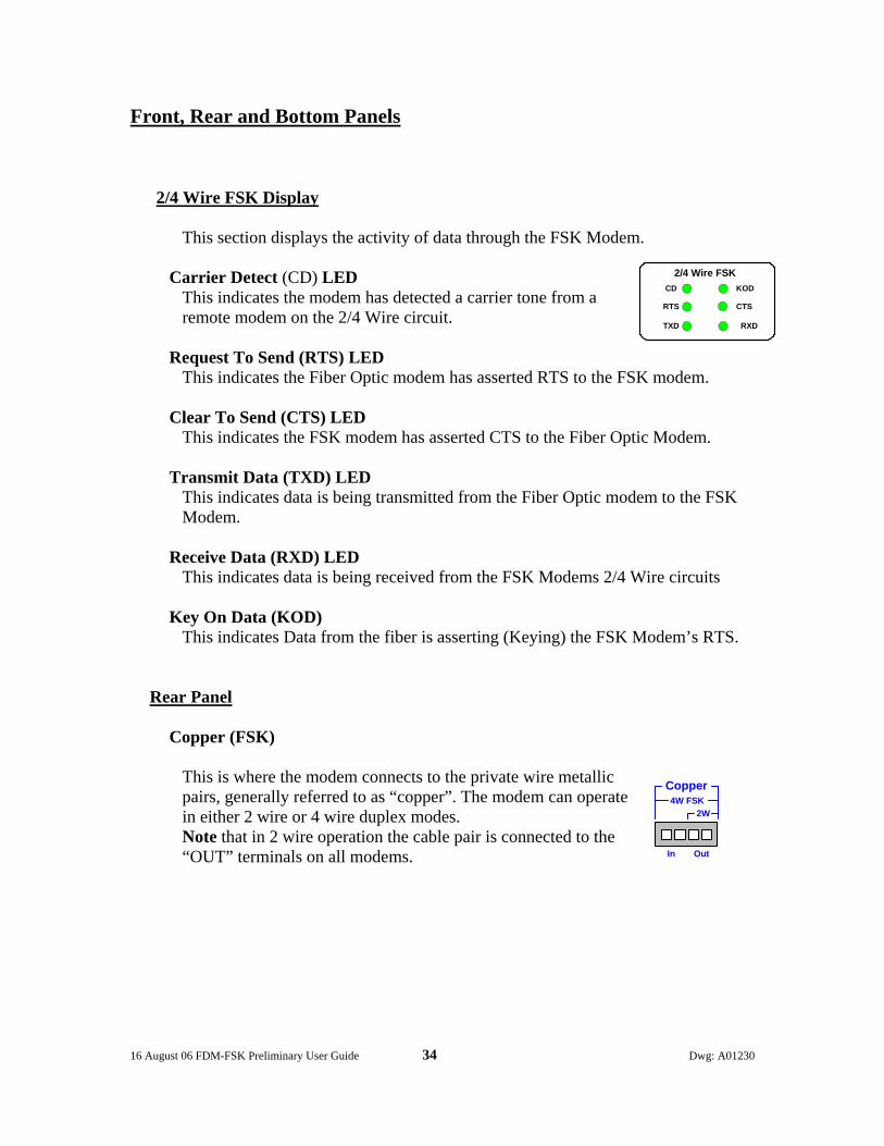
Front, Rear and Bottom Panels
2/4 Wire FSK Display
This section displays the activity of data through the FSK Modem.
Carrier Detect (CD) LED This indicates the modem has detected a carrier tone from a remote modem on the 2/4 Wire circuit.
Request To Send (RTS) LED This indicates the Fiber Optic modem has asserted RTS to the FSK modem.
Clear To Send (CTS) LED This indicates the FSK modem has asserted CTS to the Fiber Optic Modem.
Transmit Data (TXD) LED
This indicates data is being transmitted from the Fiber Optic modem to the FSK Modem.
Receive Data (RXD) LED This indicates data is being received from the FSK Modems 2/4 Wire circuits
Key On Data (KOD) This indicates Data from the fiber is asserting (Keying) the FSK Modem’s RTS.
Rear Panel
Copper (FSK)
This is where the modem connects to the private wire metallic pairs, generally referred to as “copper”. The modem can operate in either 2 wire or 4 wire duplex modes. Note that in 2 wire operation the cable pair is connected to the “OUT” terminals on all modems.
OutIn
4W FSK2W
Copper
CD
RTS
2/4 Wire FSKKOD
CTS
TXD RXD
16 August 06 FDM-FSK Preliminary User Guide 35 Dwg: A01230
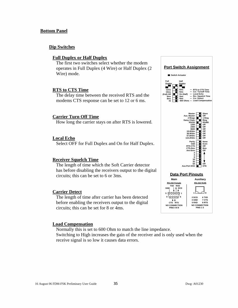
Bottom Panel
Dip Switches
Full Duplex or Half Duplex The first two switches select whether the modem operates in Full Duplex (4 Wire) or Half Duplex (2 Wire) mode.
RTS to CTS Time The delay time between the received RTS and the modems CTS response can be set to 12 or 6 ms.
Carrier Turn Off Time How long the carrier stays on after RTS is lowered.
Local Echo Select OFF for Full Duplex and On for Half Duplex.
Receiver Squelch Time The length of time which the Soft Carrier detector has before disabling the receivers output to the digital circuits; this can be set to 6 or 3ms.
Carrier Detect The length of time after carrier has been detected before enabling the receivers output to the digital circuits; this can be set for 8 or 4ms.
Load Compensation Normally this is set to 600 Ohm to match the line impedance. Switching to High increases the gain of the receiver and is only used when the receive signal is so low it causes data errors.
SlaveOff1 RingRingRS485OffOffOffOffOffOffOff
Parity NoneOdd Even
RTS-CTS OffCTS-0ms 8msAnt-Strm Off
248
1832
64 OffAux.Port DCE DTE
MasterAux. Master
2 RingsDaisy Chain
RS232120024009600
19.2Kbts38.4Kbts57.6Kbts
115.2Kbts
Port Switch Assignment
Data Port Pinouts
RS-232 RJ45
Auxiliary
1 8
2 DCD4 GND5 RXD
6 TXD7 CTS8 RTS
NO CONNECTIONPINS 1-3
DCDRXDTXD
GND
CTS RTSNO CONNECTION
PINS 4-6-9
MainRS-232 Female
15
69
FullDuplex
12ms 6ms10ms 5ms
(Full) Off On (Half)6ms 3ms8ms 4ms
Hi 600 Ohms
Switch Actuator
HalfDuplex
RTS to CTS TimeCxr. Turnoff TimeLocal EchoRcr. Squelch TimeCxr. DetectLoad Compensation

16 August 06 FDM-FSK Preliminary User Guide 36 Dwg: A01230
FSK Applications Half Duplex Operation (2 Wire ‘One Pair’)
In this mode the transmit path (Poll) is shared with the receive path (Response) so only one modem can be on the line at same time. The remote modems have to wait until the FDM-FSK modem has stopped transmitting before it can send a message back; therefore it is important to slow things down by setting the modems timing parameters to the longest times. This will result in a slower turn around time for the system. All modems on the 2 wire pair should be set with the same timing plan so as not to step over each other. Note that all 2 wire connections are made only to the OUT terminals on all modems. To shorten up this round trip delay time and therefore speed up the system response it is necessary to go to a 4wire operation (next page)
The DIP Switch diagram shows where the adjustments are made to operate in either 2 or 4 wire mode. The settings shown here are for 2 Wire which is Half Duplex operation; note you may change various timing parameters to better suite your systems requirements. KOD internal jumper J5 must be “ON”. This is confirmed when the front panel KOD LED is lit or flashing, see page 44 for details.
OUT
IN
OUT
IN OUT IN
PollResponse
PollResponse
FSK
4xxSAModem
4xxSAModem
Fiber Trunk
Fiber Trunk
T1R2
T2 R1
FDM
(Full) Off
RTS to CTS TimeCxr. Turnoff TimeLocal EchoRcr. Squelch TimeCxr. DetectLoad Compensation
FullDuplex
12ms 6ms10ms 5ms
On (Half)6ms 3ms8ms 4ms
Hi 600 Ohms
Switch Actuator
HalfDuplex
16 August 06 FDM-FSK Preliminary User Guide 37 Dwg: A01230
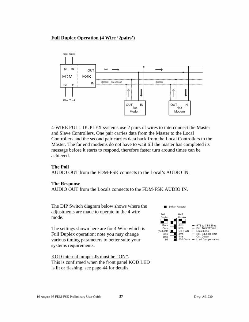
Full Duplex Operation (4 Wire ‘2pairs’)
4-WIRE FULL DUPLEX systems use 2 pairs of wires to interconnect the Master and Slave Controllers. One pair carries data from the Master to the Local Controllers and the second pair carries data back from the Local Controllers to the Master. The far end modems do not have to wait till the master has completed its message before it starts to respond, therefore faster turn around times can be achieved. The Poll AUDIO OUT from the FDM-FSK connects to the Local’s AUDIO IN.
The Response AUDIO OUT from the Locals connects to the FDM-FSK AUDIO IN.
The DIP Switch diagram below shows where the adjustments are made to operate in the 4 wire mode. The settings shown here are for 4 Wire which is Full Duplex operation; note you may change various timing parameters to better suite your systems requirements. KOD internal jumper J5 must be “ON”. This is confirmed when the front panel KOD LED is lit or flashing, see page 44 for details.
OUT IN OUT IN4xx
Modem4xx
Modem
IN
OUT
FSK
Fiber Trunk
Fiber Trunk
T1R2
T2 R1
FDMPoll
Response
(Full) Off
RTS to CTS TimeCxr. Turnoff TimeLocal EchoRcr. Squelch TimeCxr. DetectLoad Compensation
FullDuplex
12ms 6ms10ms 5ms
On (Half)6ms 3ms8ms 4ms
Hi 600 Ohms
Switch Actuator
HalfDuplex

16 August 06 FDM-FSK Preliminary User Guide 38 Dwg: A01230
A Word on Dynamic Range All Model 4xx series modems have 42db of dynamic range based on a 0dBm transmit level into a 600 Ohm load.
How far will the signal go?
This is a not an easy one to answer and can only be generalized as many factures come into play such as;
1. Condition of the cable, water penetration, corrosion etc. 2. The wire gauge, larger is better. 3. The number of modems attached to the cable pair, as you add more
modems the resulting load impedance presented to the transmitting source will decrease across the cable pair. This will cause the signal level to decrease to a point where there is insufficient signal level over induced noise to operate error free, thus limiting the transmission distance.
4. Cross talk from adjacent pairs, due to high levels or a short between adjacent pairs.
5. Induced noise due to poor grounding of the cable/cabinet. 6. Baud Rates, as the frequency goes up the transmission distance decreases,
1200 baud may go 20 miles while 19200 baud on the same cable pair will typically be less than 10 miles.
Pushing the Envelope (Making the Last Mile) Additional distance can sometimes be obtained by boosting the gain of the “last” modem on the line; this is achieved through a DIP switch and only affects this modem. This external DIP switch, marked Load Compensation, is located on the switch bank on the underside of the modem. Selecting HI will increase the gain of the modem and may give you that extra signal level to make that last mile. For normal operation leave the switch set to 600 ohms. Before installing any modem make sure that the cable pairs have Lightning Protectors installed at each modem location, please make sure that the protective device is grounded according to National Electrical Code.

16 August 06 FDM-FSK Preliminary User Guide 39 Dwg: A01230
Combined FDM-FSK APPLICATIONS
The FDM Series allows you to combine all fiber topologies, all controllers* and many legacy systems together in one polling scheme. * if your Polling Software permits.
Dai
syC
hain
TMC Master
T1
R2
R1
T2
T1
R1
R2
T2
FDMFSK
Series
North Arterial Daisy Chain
South Arterial Daisy Chain
Main Arterial-Dual Counter Rotating RingMain Arterial-Dual Counter Rotating Ring
LocalController
RS2
32
LocalController
RS2
32
LocalController
RS2
32
LocalController RS232
Dual Counter Rotating Ring Fiber FiberFDMSeries
T1
R1
R2
T2
FDMFSK
Series
LocalController RS232
T1
R2
R1
T2
FDM-FSKSeries
2 / 4 Wire FSK
2 / 4 Wire FSK
T1
R2
R1
T2
FDMSeries
RS2
32
SSRadio
SSRadio
LocalController
RS2
32
T1
R2
R1
T2FDM
Series
LocalController
RS2
32
T1
R2
R1
T2FDM
Series
LocalController
RS2
32
T1
R2
R1 T2
T1 R2
T2
R1FDM-FiberHub
Port C
Port D
Port
A
Port
B
Auxiliary
Main
Dual Ring, Daisy Chain, FSKand SS Radio Applications
Dai
sy
Cha
in
T1 R2
R1 T2
FDMSeries
LocalController RS232
FDM2SAFDM170FDM2070FDM-FSKFDM-SSRFDM-FiberHub
FDM Series
T1
R1
R2
T2
FDMSeries
LocalControllerRS232
2 / 4 Wire FSK
Dual Counter Rotating Ring
16 August 06 FDM-FSK Preliminary User Guide 40 Dwg: A01230
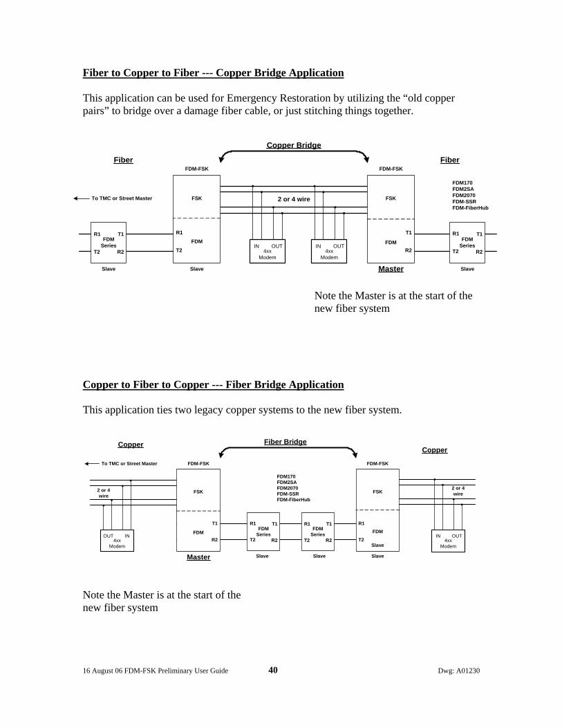
Fiber to Copper to Fiber --- Copper Bridge Application This application can be used for Emergency Restoration by utilizing the “old copper pairs” to bridge over a damage fiber cable, or just stitching things together.
Note the Master is at the start of the new fiber system
Copper to Fiber to Copper --- Fiber Bridge Application This application ties two legacy copper systems to the new fiber system.
Note the Master is at the start of the new fiber system
2 or 4 wire
OUTIN4xx
Modem
FSK
R1
T2FDM
T2
R1
FSK
T1
R2FDM FDM
SeriesFDM
Series
T1
R2
T1
R2
R1
T2
R1
T2OUTIN
4xxModem
Copper Bridge
FDM170FDM2SAFDM2070FDM-SSRFDM-FiberHub
FDM-FSK FDM-FSK
To TMC or Street Master
MasterSlave SlaveSlave
Fiber Fiber
To TMC or Street Master
2 or 4wire
Copper
T2
R1FDM
SeriesFDM
SeriesOUT IN4xx
Modem
FSK
T1
R2FDM
OUTIN4xx
Modem
FSK
R1
T2FDM
T1
R2
T1
R2
R1
T2
R1
T2
Fiber BridgeCopper
FDM170FDM2SAFDM2070FDM-SSRFDM-FiberHub
FDM-FSK FDM-FSK
2 or 4wire
Master
Slave
Slave Slave Slave
16 August 06 FDM-FSK Preliminary User Guide 41 Dwg: A01230
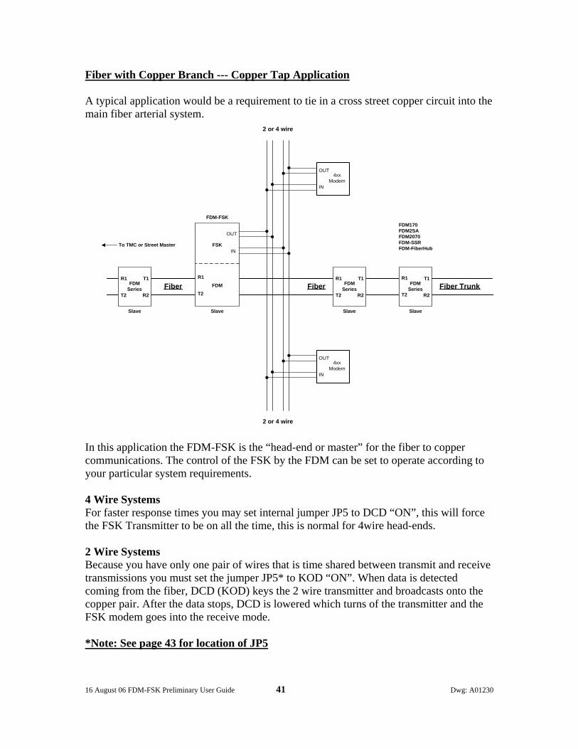
Fiber with Copper Branch --- Copper Tap Application A typical application would be a requirement to tie in a cross street copper circuit into the main fiber arterial system.
In this application the FDM-FSK is the “head-end or master” for the fiber to copper communications. The control of the FSK by the FDM can be set to operate according to your particular system requirements. 4 Wire Systems For faster response times you may set internal jumper JP5 to DCD “ON”, this will force the FSK Transmitter to be on all the time, this is normal for 4wire head-ends. 2 Wire Systems Because you have only one pair of wires that is time shared between transmit and receive transmissions you must set the jumper JP5* to KOD “ON”. When data is detected coming from the fiber, DCD (KOD) keys the 2 wire transmitter and broadcasts onto the copper pair. After the data stops, DCD is lowered which turns of the transmitter and the FSK modem goes into the receive mode. *Note: See page 43 for location of JP5
2 or 4 wire
FSK
R1
T2FDM FDM
SeriesFDM
Series
T1
R2
T1
R2
R1
T2
R1
T2
OUT
IN
4xxModem
FDM170FDM2SAFDM2070FDM-SSRFDM-FiberHub
FDM-FSK
To TMC or Street Master
Slave SlaveSlave
Fiber Fiber
IN
OUT
OUT
IN
4xxModem
FDMSeries
T1
R2
R1
T2
Slave
2 or 4 wire
Fiber Trunk

16 August 06 FDM-FSK Preliminary User Guide 42 Dwg: A01230
Factory Default Settings
The FDM is shipped from the factory with the following DIP Switch settings enabled. For obvious reasons the FDM baud rate will be set to match the FSK baud rate.
Pins Main Port DCE Data Flows Auxiliary Port DCE Data Flows
1 DCD Out NC 2 RXD Out DCD (KOD RTS) Out 3 TXD In NC 4 NC GND Common 5 GND Common RXD Out 6 NC TXD In 7 RTS In CTS Out 8 CTS Out RTS In 9 NC
FDM Anti-Streaming times are additive, e.g. 2 + 4 = 6 seconds (max. time 126 sec)
SlaveOff1 RingRingRS485OffOffOffOffOffOffOff
Parity NoneOdd Even
RTS-CTS OffCTS-0ms 8msAnt-Strm Off
248
1832 64 Off
Aux.Port DCE DTE
MasterAux. Master
2 RingsDaisy Chain
RS232120024009600
19.2Kbts38.4Kbts57.6Kbts
115.2Kbts
Port Switch Assignment
Data Port Pinouts
RS-232 RJ45
Auxiliary
1 8
2 DCD4 GND5 RXD
6 TXD7 CTS8 RTS
NO CONNECTIONPINS 1-3
DCDRXDTXD
GND
CTS RTSNO CONNECTION
PINS 4-6-9
MainRS-232 Female
15
69
FullDuplex
12ms 6ms10ms 5ms
(Full) Off On (Half)6ms 3ms8ms 4ms
Hi 600 Ohms
Switch Actuator
HalfDuplex
RTS to CTS TimeCxr. Turnoff TimeLocal EchoRcr. Squelch TimeCxr. DetectLoad Compensation
FSK Anti-Streaming time is 8 seconds.

16 August 06 FDM-FSK Preliminary User Guide 43 Dwg: A01230
KOD Jumper
KOD Jumper must be “ON”(Factory Default) for Dynamic FSK operation
Auxiliary Ports Pin # 2 (DCD) has a dual function:
1. It can be set to +5Vdc; this is used to assert RTS on an attached modem. Use only at a 4W Master location, or two modems point to point 4W.
2. It can assert DCD dynamically before data, then de-assert DCD after data;
this is used to handshake the built-in FSK modem. Use at a 2W Master or 2 or 4W Slave location.
FiberOptics
FiberOptics
DIP Switches
JP 5Aux-Ports Pin 2 FunctionsDCD or KOD Selection
KOD “ON” =
DCD “ON” = +5V
16 August 06 FDM-FSK Preliminary User Guide 44 Dwg: A01230
GDI Communications LLC Technical Services Bulletin #1
CARE AND HANDLING PROCEDURES FOR OPTICAL CONNECTORS
Author TONY ILETT
Cleanliness Is Very Important When Handling Fiber Optics Specs of dust which are invisible to the human eye, oil or grease from fingers can contaminate the end surfaces of an optical connector and reduce it’s coupling efficiency to the point of causing a system to fail. To put things into perspective the end face of an optical connector is 2.5mm in diameter. In the center of this is our optical wave-guide or glass fiber; this has a diameter of 125 microns (125 millionth of a meter) and is about the size of a human hair. In the center of this glass fiber is an area called the Core, which in Multimode fiber is 50 or 62.5microns in diameter and is invisible to the naked eye, it is this core that carries our optical signal. As stated Multimode core diameters are usually 50 microns (Europe) or 62.5 microns (North America), but in the long haul, high bandwidth world of Singlemode fibers the core size is 80% smaller than the fibers diameter of 125 microns and measures less than 10 microns across! It should now be obvious that a spec of dust, invisible the naked eye, can prevent your communications system from working, so: ------ KEEP IT CLEAN! Materials needed to clean Optical Patchcords
1. Wet Method Typically these are lens grade tissue pre-moistened with a solvent that has a concentration of 90% or better of Isopropyl Alcohol and sealed in a foil sachet.
or A lens grade tissue, which is then moistened with 90% or better Isopropyl Alcohol. Do not use rubbing alcohol as this contains oil for lubrication and will leave a smear or film which will degrade the Optical Return Loss and also cause particulate matter to stick to it.
or Dry Method
This involves using a special device that looks like a small videocassette tape containing a paper like material instead of magnetic tape. The connectors ferrule is inserted into an opening and the tape is wound on thus polishing the end face. There are several versions of this device readily available from supply houses. Note: This only polishes the end surface and does not clean the ferrules cylindrical surface that contributes to axial alignment.

16 August 06 FDM-FSK Preliminary User Guide 45 Dwg: A01230
2. Air Duster
A can of compressed inert gas with a plastic extension tube. Make sure that any liquid propellant has been discharged from the tube before using on the optics.
3. Lint Free Tissues
Lint free tissues used to clean fiber optic surfaces. Does not introduce any contaminates. Always keep sealed in a Ziploc bag to avoid contamination when not in use. Do not re-use the tissue, discard it.
4. Dust Caps
A supply of Clean Dust Caps, note that there are two sizes, one for connectors, the other one is slightly smaller and is used for the optical ports on patch-panels and transmission devices. Store them in a Clean Zip-Lock Bag.
The following scenario outlines the steps taken when disconnecting and then re-mating one end of a Patchcord from an optical device, such as a patch-panel or transmission equipment. WARNING! Invisible Laser Energy Can Damage Your Eyes
• Do not look into the end of an Optical Connector that is attached to a
fiber, it may be emitting potentially harmful energy that can damage your eyes, first disconnect the other end or turn the power “Off” on the transmitting device.
• Do not look into the transmitting port of an Optical Transmitter with out
first turning the power “Off” to that device.
Note: Visible Red LED’s (820nm Multimode) are low power devices that can be viewed at a safe distance of two to three feet.
Disconnecting the Optical Connector
1. Any accumulation of dust that has settled around the optical connectors must first be removed by using short bursts of compressed air from the Air Duster. In high dust areas use pre-moistened tissues or lint free tissues moistened with alcohol to wipe off excessive dust and then use the Air Duster, this will reduce the possibility of dust contaminating the optical connector as well as the optical receptacle. Do not re-use a tissue, discard it.
16 August 06 FDM-FSK Preliminary User Guide 46 Dwg: A01230
2. Disconnect the optical connector and put a clean protective dust cap over the end. If you don’t have a dust cap use a clean Ziploc bag or worst case temporary suspend the connector in free air and make sure it does not touch any other surface. Do not leave the exposed receptacle without any protection; cap it with a clean dust cap!
Reconnecting the Optical Connector
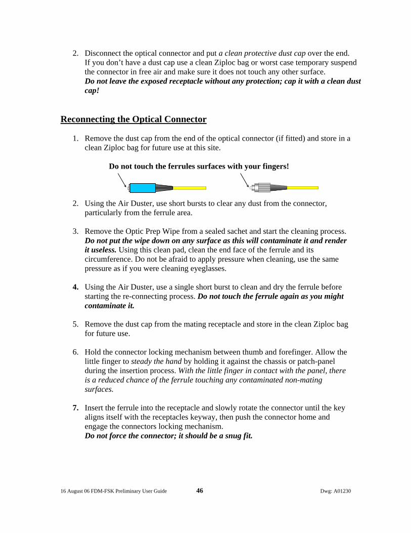
1. Remove the dust cap from the end of the optical connector (if fitted) and store in a clean Ziploc bag for future use at this site.
Do not touch the ferrules surfaces with your fingers!
2. Using the Air Duster, use short bursts to clear any dust from the connector, particularly from the ferrule area.
3. Remove the Optic Prep Wipe from a sealed sachet and start the cleaning process.
Do not put the wipe down on any surface as this will contaminate it and render it useless. Using this clean pad, clean the end face of the ferrule and its circumference. Do not be afraid to apply pressure when cleaning, use the same pressure as if you were cleaning eyeglasses.
4. Using the Air Duster, use a single short burst to clean and dry the ferrule before
starting the re-connecting process. Do not touch the ferrule again as you might contaminate it.
5. Remove the dust cap from the mating receptacle and store in the clean Ziploc bag
for future use.
6. Hold the connector locking mechanism between thumb and forefinger. Allow the little finger to steady the hand by holding it against the chassis or patch-panel during the insertion process. With the little finger in contact with the panel, there is a reduced chance of the ferrule touching any contaminated non-mating surfaces.
7. Insert the ferrule into the receptacle and slowly rotate the connector until the key
aligns itself with the receptacles keyway, then push the connector home and engage the connectors locking mechanism. Do not force the connector; it should be a snug fit.

16 August 06 FDM-FSK Preliminary User Guide 47 Dwg: A01230
Contents of this user guide may not be copied or published without the written consent of GDI Communications LLC, Verdi, Nevada. The contents of this user guide are deemed to be correct at the time of publishing and are offered as a guide only; GDI Communications LLC is not liable for any inaccuracies or omissions.