fdu foundry degassing unit - foundry - … · fdu foundry degassing units are a melt treatment...
TRANSCRIPT
C O A T I N G S F I LT R A T I O N F E E D I N G S Y S T E M S M E LT S H O P R E F R A C T O R I E S M E T A L L U R G I C A L A N D P O U R I N G C O N T R O L B I N D E R S C R U C I B L E S
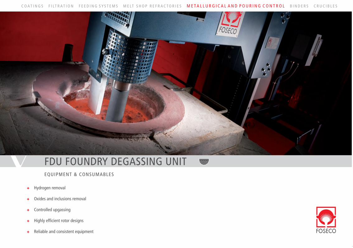
FDU FOUNDRY DEGASSING UNITEQUIPMENT & CONSUMABLES
+Hydrogen removal
+Oxides and inclusions removal
+Controlled upgassing
+Highly effi cient rotor designs
+Reliable and consistent equipment
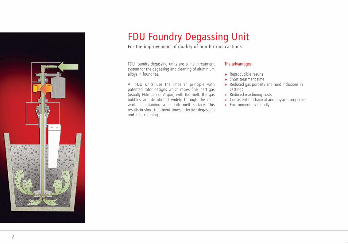
FDU foundry degassing units are a melt treatment system for the degassing and cleaning of aluminiumalloys in foundries.
All FDU units use the impeller principle with patented rotor designs which mixes fine inert gas (usually Nitrogen or Argon) with the melt. The gas bubbles are distributed widely through the melt whilst maintaining a smooth melt surface. This results in short treatment times, effective degassing and melt cleaning.
FDU Foundry Degassing Unit For the improvement of quality of non ferrous castings
The advantages
+ Reproducible results+ Short treatment time+Reduced gas porosity and hard inclusions in
castings+ Reduced machining costs+ Consistent mechanical and physical properties+ Environmentally friendly
2
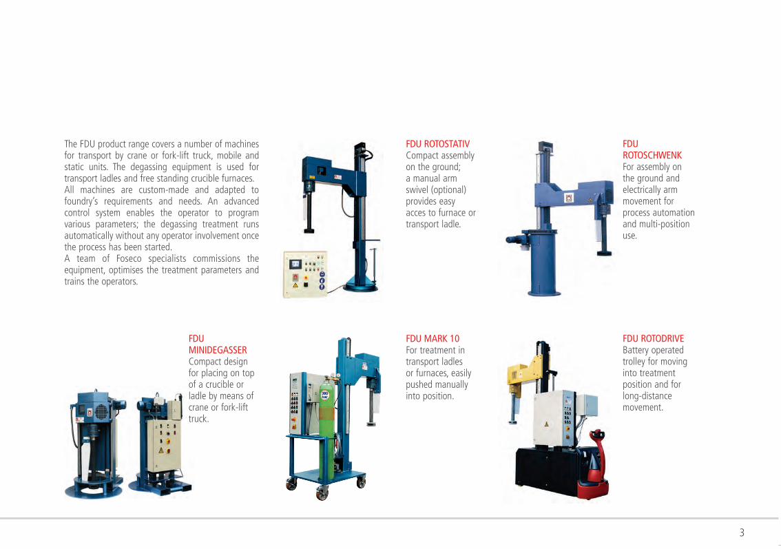
The FDU product range covers a number of machines for transport by crane or fork-lift truck, mobile and static units. The degassing equipment is used for transport ladles and free standing crucible furnaces.All machines are custom-made and adapted to foundry’s requirements and needs. An advanced control system enables the operator to program various parameters; the degassing treatment runs automatically without any operator involvement once the process has been started.A team of Foseco specialists commissions the equipment, optimises the treatment parameters and trains the operators.
FDU MARK 10For treatment intransport ladlesor furnaces, easilypushed manuallyinto position.
FDU ROTOSTATIVCompact assembly on the ground; a manual arm swivel (optional) provides easy acces to furnace or transport ladle.
FDU MINIDEGASSERCompact design for placing on top of a crucible or ladle by means of crane or fork-lift truck.
FDU ROTODRIVEBattery operatedtrolley for movinginto treatmentposition and forlong-distancemovement.
FDU ROTOSCHWENKFor assembly onthe ground andelectrically armmovement forprocess automationand multi-positionuse.
3
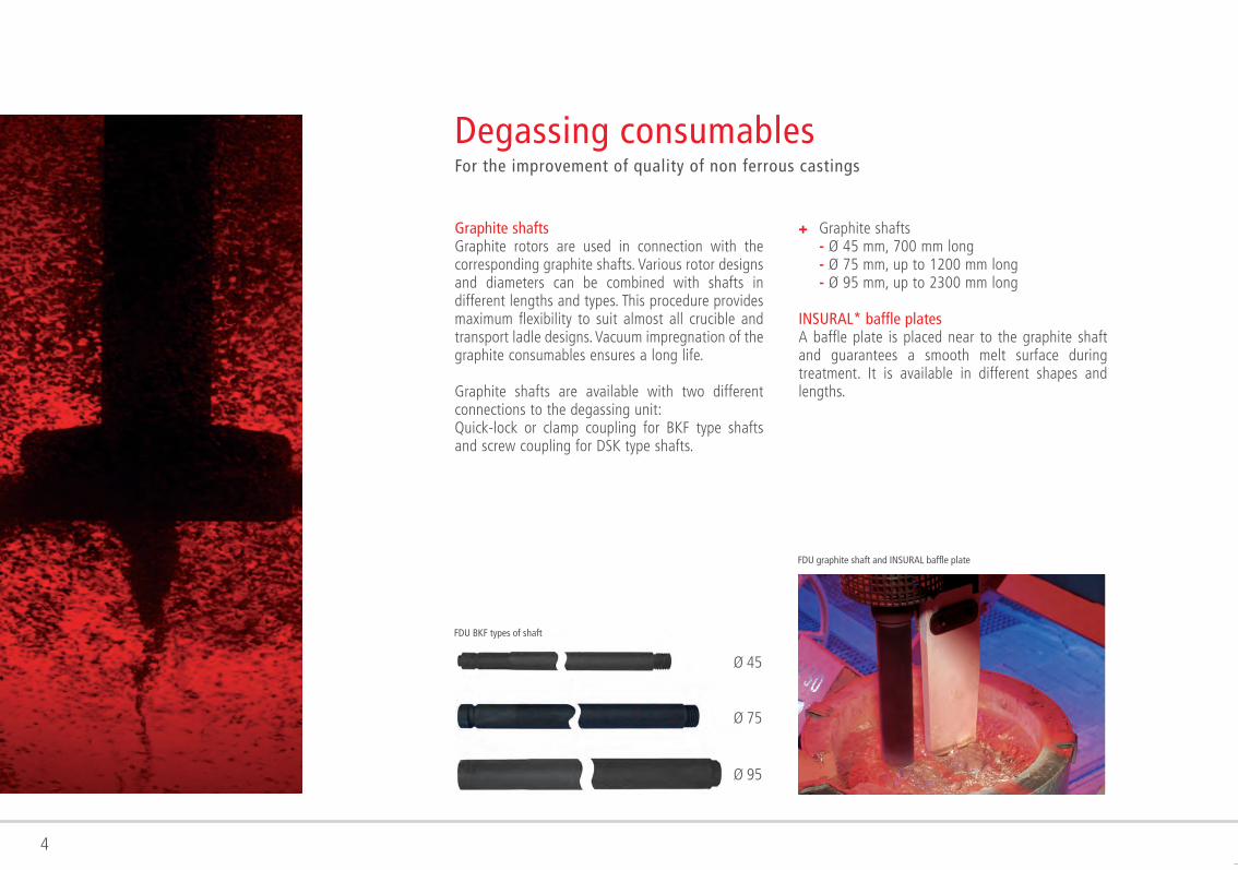
Graphite shaftsGraphite rotors are used in connection with the corresponding graphite shafts. Various rotor designs and diameters can be combined with shafts in different lengths and types. This procedure provides maximum flexibility to suit almost all crucible and transport ladle designs. Vacuum impregnation of the graphite consumables ensures a long life.
Graphite shafts are available with two different connections to the degassing unit:Quick-lock or clamp coupling for BKF type shafts and screw coupling for DSK type shafts.
Degassing consumablesFor the improvement of quality of non ferrous castings
4
Ø 45
Ø 75
Ø 95
+Graphite shafts - Ø 45 mm, 700 mm long - Ø 75 mm, up to 1200 mm long - Ø 95 mm, up to 2300 mm long
INSURAL* baffle platesA baffle plate is placed near to the graphite shaft and guarantees a smooth melt surface during treatment. It is available in different shapes and lengths.
FDU graphite shaft and INSURAL baffle plate
FDU BKF types of shaft
5
The rotor design is the key for optimal cleaning and degassing the melt; rotors must fulfill the following functions:+ small size of purge gas bubbles+ homogeneous bubble distribution across the
whole volume+ good melt movement and mixing+ low melt surface movement
Foseco intensively investigate existing rotor designs combined with theoretical studies, simulations, extensive modelling and practical tests to further improve the degassing performance.
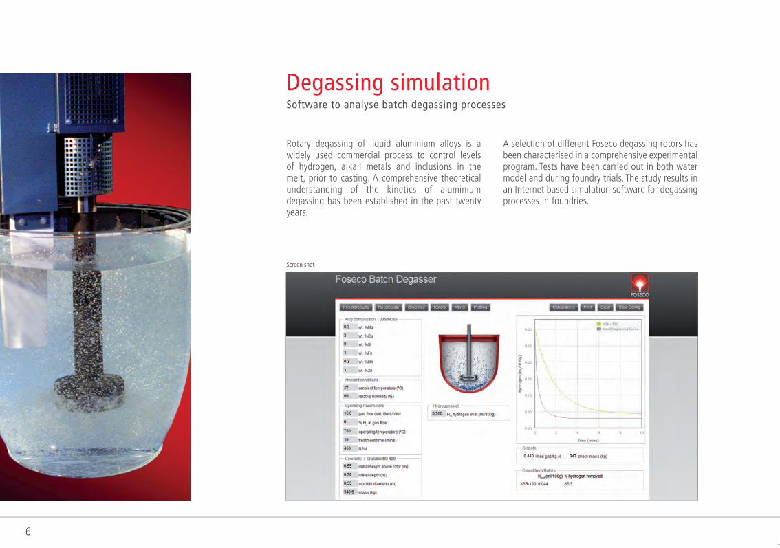
FDU XSR graphite rotorThe XSR rotor type can be combined with all graphite shafts. Different diameters from 140 to 250 mm fit nearly all geometries and sizes of treatment vessels. Turbo cuts in the upper section of the rotor further reduce the size of the inert gas bubbles thus maximising the surface area of the bubbles for a given volume of treatment gas.
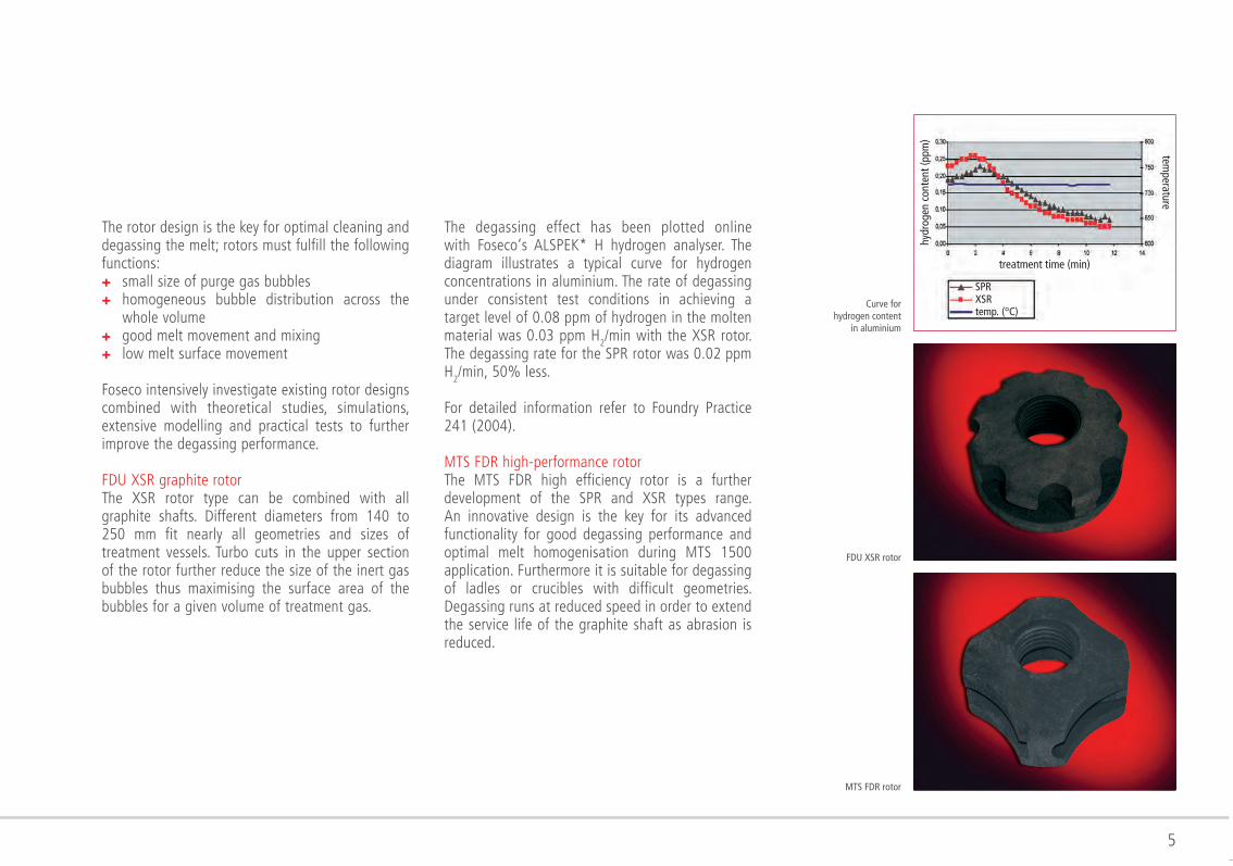
The degassing effect has been plotted online with Foseco‘s ALSPEK* H hydrogen analyser. The diagram illustrates a typical curve for hydrogen concentrations in aluminium. The rate of degassing under consistent test conditions in achieving a target level of 0.08 ppm of hydrogen in the molten material was 0.03 ppm H
2/min with the XSR rotor. The degassing rate for the SPR rotor was 0.02 ppm H2/min, 50% less.
For detailed information refer to Foundry Practice 241 (2004).
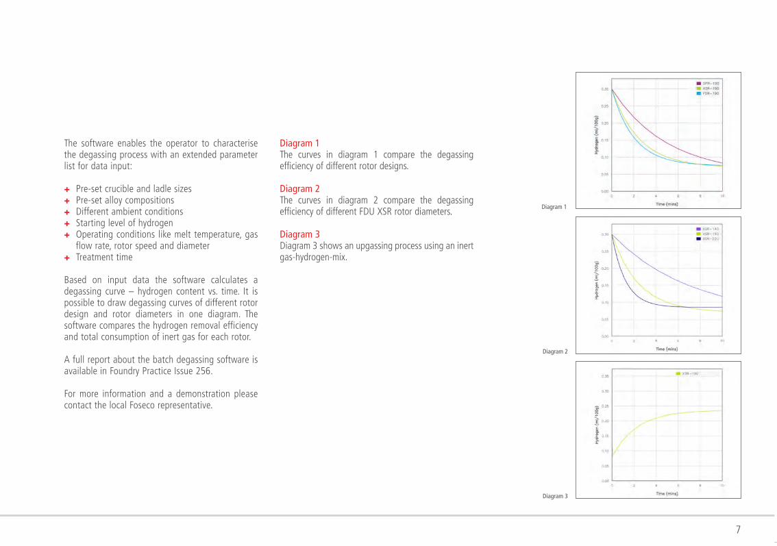
MTS FDR high-performance rotorThe MTS FDR high efficiency rotor is a further development of the SPR and XSR types range. An innovative design is the key for its advanced functionality for good degassing performance and optimal melt homogenisation during MTS 1500 application. Furthermore it is suitable for degassing of ladles or crucibles with difficult geometries. Degassing runs at reduced speed in order to extend the service life of the graphite shaft as abrasion is reduced.
FDU XSR rotor
MTS FDR rotor
Curve for hydrogen content
in aluminium
temperature
hydr
ogen
con
tent
(ppm
)
treatment time (min)
SPRXSRtemp. (°C)
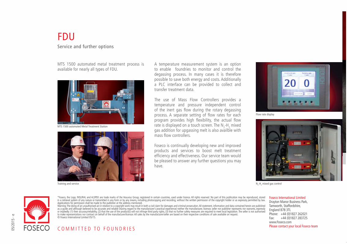
Rotary degassing of liquid aluminium alloys is a widely used commercial process to control levels of hydrogen, alkali metals and inclusions in the melt, prior to casting. A comprehensive theoretical understanding of the kinetics of aluminium degassing has been established in the past twenty years.
Degassing simulationSoftware to analyse batch degassing processes
A selection of different Foseco degassing rotors has been characterised in a comprehensive experimental program. Tests have been carried out in both water model and during foundry trials. The study results in an Internet based simulation software for degassing processes in foundries.
6
Screen shot
7
The software enables the operator to characterise the degassing process with an extended parameter list for data input:
+ Pre-set crucible and ladle sizes+Pre-set alloy compositions+Different ambient conditions+Starting level of hydrogen+Operating conditions like melt temperature, gas
flow rate, rotor speed and diameter+Treatment time
Based on input data the software calculates a degassing curve – hydrogen content vs. time. It is possible to draw degassing curves of different rotor design and rotor diameters in one diagram. The software compares the hydrogen removal efficiency and total consumption of inert gas for each rotor.
A full report about the batch degassing software is available in Foundry Practice Issue 256.
For more information and a demonstration please contact the local Foseco representative.
Diagram 1The curves in diagram 1 compare the degassing efficiency of different rotor designs.
Diagram 2The curves in diagram 2 compare the degassing efficiency of different FDU XSR rotor diameters.
Diagram 3Diagram 3 shows an upgassing process using an inert gas-hydrogen-mix.
Diagram 1
Diagram 2
Diagram 3
05/2
015
· e
C O M M I T T E D T O F O U N D R I E S
FDUService and further options
*Foseco, the Logo, INSURAL and ALSPEK are trade marks of the Vesuvius Group, registered in certain countries, used under licence. All rights reserved. No part of this publication may be reproduced, stored in a retrieval system of any nature or transmitted in any form or by any means, including photocopying and recording, without the written permission of the copyright holder or as expressly permitted by law. Applications for permission shall be made to the publisher at the address mentioned. Warning: The doing of an unauthorised act in relation to a copyright work may result in both a civil claim for damages and criminal prosecution. All statement, information and data contained herein are published as a guide and although believed to be accurate and reliable (having regard to the manufacturer’s practical experience) neither the manufacturer, licensor, seller nor publisher represents nor warrants, expressly or impliedly: (1) their accuracy/reliability, (2) that the use of the product(s) will not infringe third party rights, (3) that no further safety measures are required to meet local legislation. The seller is not authorised to make representations nor contract on behalf of the manufacturer/licensor. All sales by the manufacturer/seller are based on their respective conditions of sale available on request.© Foseco International Limited 05/15.
Foseco International LimitedDrayton Manor Business Park,Tamworth, Staffordshire,England B78 3TLPhone: +44 (0)1827 262021Fax: +44 (0)1827 283725www.Foseco.comPlease contact your local Foseco team
MTS 1500 automated metal treatment process is available for nearly all types of FDU.
MTS 1500 automated Metal Treatment Station
Flow rate display
N2-H2 mixed gas controlTraining and service
A temperature measurement system is an option to enable foundries to monitor and control the degassing process. In many cases it is therefore possible to save both energy and costs. Additionally a PLC interface can be provided to collect and transfer treatment data.
The use of Mass Flow Controllers provides a temperature and pressure independent control of the inert gas fl ow during the rotary degassing process. A separate setting of fl ow rates for each program provides high fl exibility, the actual fl ow rate is displayed on a touch screen. The N2-H2 mixed gas addition for upgassing melt is also availble with mass fl ow controllers.
Foseco is continually developing new and improved products and services to boost melt treatment effi ciency and effectiveness. Our service team would be pleased to answer any further questions you may have.