fea analysis documentation
TRANSCRIPT

FEA Analysis
Maria Krutikovawith contributions from Teal Dowd
Background Information
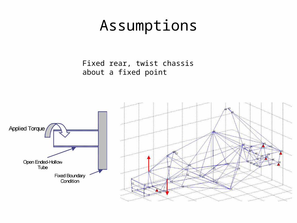
Assumptions
Fixed rear, twist chassis about a fixed point
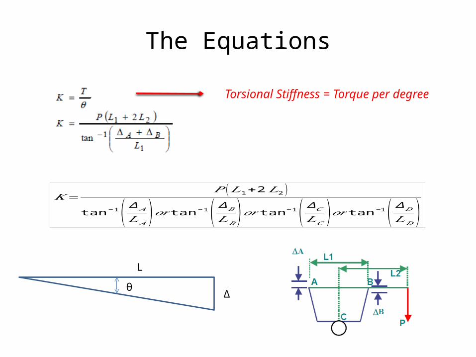
The Equations
𝐾=𝑃 (𝐿1+2𝐿2 )
tan−1( ∆𝐴
𝐿𝐴)𝑜𝑟 tan−1( ∆𝐵𝐿𝐵
)𝑜𝑟 tan−1( ∆𝐶𝐿𝐶)𝑜𝑟 tan−1( ∆𝐷
𝐿𝐷)
L
θΔ
Torsional Stiffness = Torque per degree

2014 Analysis

Meshed 2014 Chassis
Assumption: all tubes are 1”x .049” thickness!
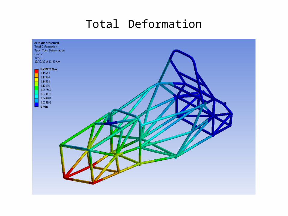
Total Deformation

Directional Deformation Y-Axis

Maximum Stress
Max Stress significantly under ultimate tensile stressFactor of Safety = 3.5

𝐾=𝑃 (𝐿1+2𝐿2 )
tan−1( ∆𝐴
𝐿𝐴)𝑜𝑟 tan−1( ∆𝐵𝐿𝐵
)𝑜𝑟 tan−1( ∆𝐶𝐿𝐶)𝑜𝑟 tan−1( ∆𝐷
𝐿𝐷)
𝐾=500 (33 )
tan−1( .1148.25 )
𝐾=1736𝑙𝑏∗ 𝑓𝑡𝑑𝑒𝑔
Torsional Stiffness

2015 Analysis

2015 Chassis
Assumption: all tubes are 1”x .049” thickness!

Loads and Boundary Conditions
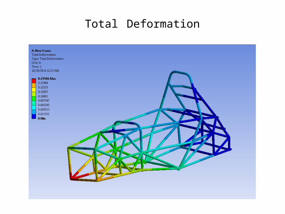
Total Deformation
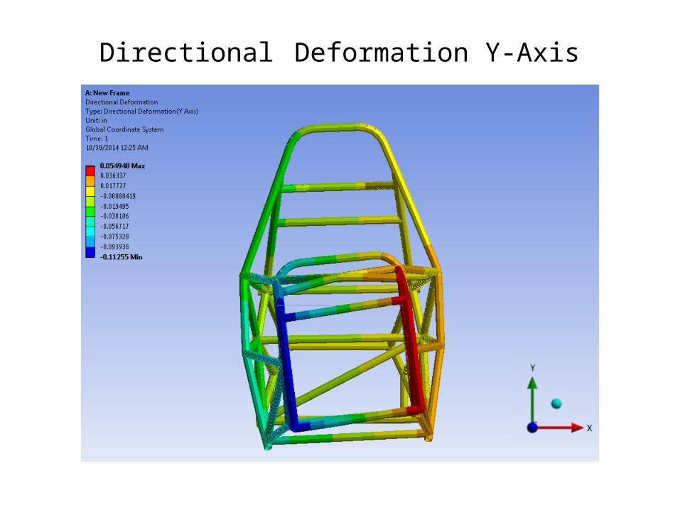
Directional Deformation Y-Axis

Maximum Stress
Max Stress significantly under ultimate tensile stressFactor of Safety = 2.5
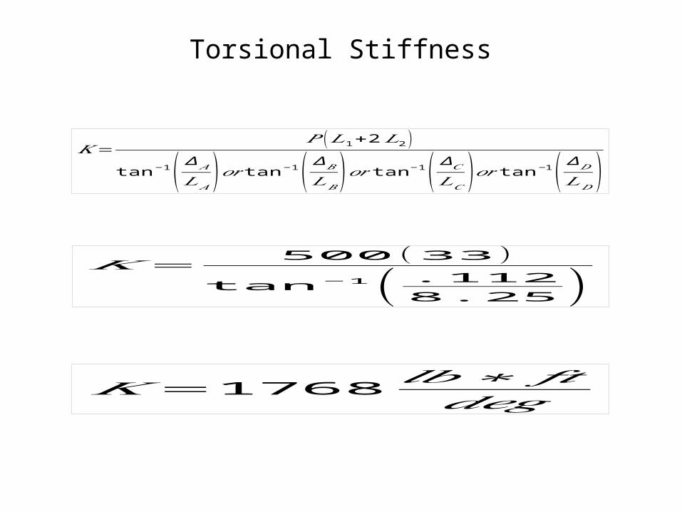
𝐾=𝑃 (𝐿1+2𝐿2 )
tan−1( ∆𝐴
𝐿𝐴)𝑜𝑟 tan−1( ∆𝐵𝐿𝐵
)𝑜𝑟 tan−1( ∆𝐶𝐿𝐶)𝑜𝑟 tan−1( ∆𝐷
𝐿𝐷)
𝐾=500 (33 )
tan−1( .1128.25 )
𝐾=1768𝑙𝑏∗ 𝑓𝑡𝑑𝑒𝑔
Torsional Stiffness