fea and experimental analysis of energy absorption
TRANSCRIPT

25 Page 25-37 © MAT Journals 2019. All Rights Reserved
Journal of Mechanical and Mechanics Engineering
e-ISSN: 2581-3722
Volume 5 Issue 1
FEA and Experimental Analysis of Energy Absorption
Characteristic of the Circular Column with and without
Honeycomb Structure
Pratapsinha Patil1, Prof. P. G. Karajagi
2
1P.G Student
, 2 Professor,
1,2Department of Mechanical Engineering,
Dr. D. Y. Patil School of engineering, Pune, Maharashtra, India
Email: [email protected]
Abstract
The Energy absorbing elements are very important in many crucial engineering fields, such as
aircraft, spacecraft, vehicle and ship. This study investigates the crushing (Post buckling)
response and energy absorption characteristics of the circular aluminium column with and
without honeycomb structure to reduce injury to the passengers and damage to the vehicle.
Post-buckling phenomenon has advantages in many engineering applications. Buckling has
greater impact on the structures of automobiles. It is necessary to study the post buckling
response of the metal structures. CAD model of the circular aluminium column is prepared
using CATIA V5. FEA Analysis is carried out on the FEA model using Abaqus/Explicit®.
Validation of post buckling results will be done using the experimental testing results obtained
using UTM. The result & conclusion will be drawn after making the comparison between the
experimental and analysis result.
Index Terms: Thin-walled circular aluminum column; Abaqus/Explicit®; Energy absorption;
Nonlinear; CATIA V5.)
INTRODUCTION
Energy absorbing elements are very
important in many crucial engineering
fields, such as aircraft, spacecraft, vehicle
and ship. To absorb the impact kinetic
energy different elements are designed
such as the cellular materials or thin-walled
tubes. The thin-wall tubes are stacked
laterally as an energy absorbing system on
the highway to absorb impact energy and
avoid injuries or protect delicate structures
of vehicle, which may enhance the
crashworthiness of the vehicle body
structure during lateral impact [1].
Metal thin-walled tubes are expected to
absorb the maximum amount of impact
energy by controlling the collapse mode in
a series of folding and hinging during the
plastic deformation process. Many studies
have investigated the effects of various
geometry shapes such as circular [1, 2, 3,
6], square [3, 5], straight tubes and tapered
or graded tubes [4] on the energy
absorption capability. The ways to improve
the energy absorption performance of metal
thin-walled tubes by changing sectional
shapes is mostly saturated because of
limitations of mechanical processing
shaping methods. Composite tubes formed
by combining metal thin-walled tubes with
other components have sprung up and
exhibit many favorable characteristics [2].
Combination of thin-walled tube and
lightweight foam is anticipated to enhance
the energy absorption of the structure since
both the tube and foam material have high
energy absorption capacities [1].
Crashworthiness of foam-filled columns is
the focus of research for the last two
decades due to the development of metallic
foam materials. Mirfendereski et al.
26 Page 25-37 © MAT Journals 2019. All Rights Reserved
Journal of Mechanical and Mechanics Engineering
e-ISSN: 2581-3722
Volume 5 Issue 1
considered the experimental and numerical
analysis of the crashworthiness
characteristics of foam-filled straight,
double-tapered, triple-tapered and frusta
geometries for static and dynamic impact
loads. They found that the initial peak load
was de-creased as the number of oblique
sides increased. Ahmad and
Tham-biratnam determined that a
foam-filled conical column absorbs
significantly more energy and have a
higher mean crush load than an empty one.
Goel compared the energy absorption
capability of empty and foam-filled
columns with different cross-sections under
impact loading and determined that
foam-filled bi-tubular and tri-tubular
structures absorb more energy than
mono-tubular foam-filled columns. They
determined that foam-filled square columns
displayed the highest crash performance.
The common main observation of these
studies was that the energy absorption
capacity can be increased by using metallic
foams [4].
To improve the crashworthiness
performance of foam-filled structures, the
effects of cross-sectional geometry and
foam densities have been widely
investigated. Langseth and Hopperstad
reported that increasing the wall thickness
and foam density increased the SEA values
of the columns under axial loading
conditions. Hanssen et al. investigated the
crushing behaviour of circular and square
columns filled with aluminum foam under
static and dynamic loads. To predict the
average force, the maximum force, and the
effective crushing distance, the theoretical
formulations was developed. Sun et al.
compared the energy absorption capacity of
functionally graded foam-filled column
structures and the uniform foam-filled
column structures. They found that the
crashworthiness performance of
functionally graded foam-filled column is
better than that of the uniform foam-filled
column. They also found that the energy
absorption capacity was dependent on the
foam density. Santosa and Wierzbicki
studied the effect of low-density filler
material on the axial crushing resistance of
square columns under quasi-static loading
condition [4]. However, foam-filled single
and double square tubes have a strong
tendency to undergo tearing of the tube
corners, which is inefficient and difficult to
control [3]
Different types of energy absorber systems
have been proposed and efforts need to be
devoted to more thorough understanding of
the crashing behaviour and energy
absorption characteristics of different
structures. Metal honeycombs have long
been recognized as an excellent lightweight
structural material due to their strength and
energy absorption properties [7]. It is
necessary to perform a comprehensive
comparative analysis on the
crashworthiness of empty and an aluminum
honeycomb filled thin-walled
tubes/columns and to present a set of
well-accepted criteria to appropriately
evaluate the energy absorption capacity of
the structures.
In the present study, FEA and experimental
analysis of post-buckling response and
energy absorption of the circular
aluminium columns with and without
honeycomb structure is carried out using
Abaqus/Explicit® code and this is a
comparative analysis between circular
aluminium columns with and without
honeycomb structure. The
load-displacement characteristics and
energy absorption ability of these structures
are investigated and generally compared.
LITERATURE REVIEW
Literature Survey Zhifang Liu, et al [1] “Experimental and
theoretical investigations on lateral
crushing of aluminum foam-filled circular
tubes”2017. Experimental and theoretical
investigation was carried out on
mechanical response and energy absorption
of aluminum foam-filled and empty
27 Page 25-37 © MAT Journals 2019. All Rights Reserved
Journal of Mechanical and Mechanics Engineering
e-ISSN: 2581-3722
Volume 5 Issue 1
circular tubes with different geometry.
Each specimen including foam-filled
circular and empty circular tubes were
compressed laterally between two rigid
plates. They studied the effects of the
geometrical characteristics of specimens
and densities of aluminum foam on
deformation and energy absorption of the
foam-filled and empty circular tubes. Their
results show that the presence of aluminum
foam filled in the circular tubes changes the
deformation modes and increases the
energy absorption of the foam-filled
circular tubes. They proposed an analytical
model for the plastic deformation of the
foam-filled circular tubes under the lateral
loading. They obtained the relationship
between lateral loading and energy
absorption of the foam-filled circular tubes.
Fei Wu, et al [2] “Quasi-static axial crush
response and energy absorption of layered
composite structure formed from novel
crochet-sintered mesh tube and thin walled
tube”2018.
The quasi-static crush response and energy
absorption of the layered composite
circular tubes formed by matching
thin-walled tubes with novel
crochet-sintered mesh tubes (CSMTs) was
investigated. The CSMTs are suitable for
application as energy absorption
components to improve the load-bearing
capacity and energy absorption of
thin-walled tubes. As compared to those of
metal thin-walled tube, the load-carrying
capacity, energy absorption, effective
stroke ratio and crushing force efficiency of
layered composite tubes is more. The
energy absorption property can be
increased by 106%. Compared to the
two-layered structures, the load-carrying
capacity, energy absorption, crushing force
efficiency and specific energy absorption of
the three-layered structure are higher.
These show that the former has better
structure crashworthiness than the latter.
Zhibin Li, et al [3] “Comparative analysis
of crashworthiness of empty and
foam-filled thin walled tubes”2017.
The investigation was conducted on two
types of empty aluminum alloy tubes
(circular and square) and five types of
aluminum ex-situ foam filled tube
structures by using Quasi-static axial
compression tests. This investigation
covered the load-deformation
characteristics, deformation mode and
energy absorption ability of these
structures. The specific energy absorption,
the energy-absorbing effectiveness factor,
etc. parameters were compared related to
their crashworthiness. The effect of
physical dimension on the crashworthiness
of these structures was studied thoroughly.
Compared to those of thin-walled square
structures, the averaged crush force,
specific energy absorption, energy
absorption per stroke and energy-absorbing
effectiveness factor are higher in
thin-walled circular structures. Foam-filled
single and double circular tube structures
are recommended as crash worthy
structures due to their high crush force
efficiency and energy absorbing efficiency.
M. Altin, et al [4] “Foam filling options for
crashworthiness optimization of
thin-walled multi-tubular circular
columns”2018.
There is an increasing trend in using
aluminum foam-filled columns in crash
management systems due to their light
weight in automotive industry. The main
goal of this study is to optimize the
crashworthiness of aluminum foam-filled
thin-walled multi-tubular circular columns
under quasi-static loading. The existing
studies in the literature considered only
lateral foam filling (the foam lateral
dimension is variable, and the foam height
is equal to the column height). In the
present study, we considered both lateral
and axial foam filling and compared the
performances of these two options. In
optimization, the column thicknesses, taper
angle, foam density, and foam
28 Page 25-37 © MAT Journals 2019. All Rights Reserved
Journal of Mechanical and Mechanics Engineering
e-ISSN: 2581-3722
Volume 5 Issue 1
height/diameter are considered as design
variables. The quasi-static responses of the
columns are determined through explicit
dynamic Finite Element Analysis (FEA)
using LS-DYNA software and validated
with quasi-static tests conducted in our
facilities. Response surface-based
crashworthiness optimization of the
columns for maximum Crush Force
Efficiency (CFE) and maximum Specific
Energy Absorption (SEA) is performed. It
is found that lateral foam filling is superior
to axial foam filling in terms of both CFE
and SEA maximization. The maximum
CFE obtained through lateral foam filling is
19% larger than the maximum CFE
obtained through axial foam filling.
Similarly, the maximum SEA obtained
through lateral foam filling is 6% larger
than the maximum SEA obtained through
axial foam filling. For both CFE and SEA
maximization, the columns should be
tri-tubular type and have a large thickness
and a taper angle. To attain the maximum
CFE, foam should be designed with large
density and medium foam diameter.
However, foam plays an adverse role in
maximization of SEA because of its
weight. The increase in energy absorption
obtained by using foam does not
compensate the additional weight
introduced by the foam.
Xuehui Yu, et al [5] “Crushing and energy
absorption of density-graded foam-filled
square columns: experimental and
theoretical investigations”2018.
The static axial crushing and energy
absorption of density-graded aluminum
foam-filled square metal columns are
experimentally and theoretically
investigated. Typical deformation modes
are observed in experiments, such as
symmetric, asymmetric, extension and
rupture modes. Theoretical analysis is
carried out and the predictions are in good
agreement with the experimental results.
This paper discusses the effects of gradient
pattern, density difference, average density
of foam, and wall thickness on the crushing
of foam-filled columns. It is shown that the
density-graded aluminum foam-filled
square metal column is a novel topological
structure with higher energy absorption,
higher load carrying capacity and much
higher crushing force efficiency.
A. Praveen Kumar, et al [6] “Crush
performance analysis of combined
geometry tubes under axial compressive
loading”2017.
Their research deals with crushing and
energy absorption characteristics of
combined geometry tubes composed of a
cylindrical segment with end plain cap,
Hemispherical cap and shallow spherical
cap. The aluminium geometrical tubes were
of three different thicknesses (1.65 mm.
2.05 mm 6 2.67 mm) and their large
deformation was obtained by crushing
between two flat plates under axial
compressive loading. They compared the
performance of combined geometrical
tubes with non-capped tubes. It has been
found that maximum initial peak load can
be controlled to obtain convenient crush
protection systems using combined
geometrical tubes. A three-dimensional
non-linear finite element analysis was
carried out using Abaqus/Explicit® code to
gain more detailed insight into the crushing
process. The numerically predicted
crushing force and fold formation were
found to be in good agreement with the
experimental results. The results showed
that combined geometry tubes can stabilize
the deformation behaviour and hence a
good alternative as a controllable energy
absorption element was found.
Tomasz Wierzbicki [7] “Crushing analysis
of metal honeycombs”1983.
He showed a method for determining the
crushing strength of hexagonal cell
structures subjected to axial loading is
given. Energy considerations in
conjunction with a minimum principle in
29 Page 25-37 © MAT Journals 2019. All Rights Reserved
Journal of Mechanical and Mechanics Engineering
e-ISSN: 2581-3722
Volume 5 Issue 1
plasticity is base of this investigation. The
analysis of a system of collapsing angle
elements undergoing bending and
extensional deformations is equivalents to
this problem. Initially an arbitrary angle
between panels was developed for
investigation and then is specified for the
120 ° angle, appropriate for the hexagonal
cell structures. The relationship between
the crushing force and the wavelength of
the local folding wave to the wall thickness
and diameter of the cell was derived. The
comparison between the theoretical
solution and the experimental results
published in the literature to obtain an
excellent correlation for the wide range of
geometrical parameters involved. These
results replace the less accurate earlier
analysis of the same problem. To provide a
simple relation by which hexagonal cell
structures can be designed for use as energy
absorbers in impact loading situations was
the main purpose of this study.
Closure of the Review
Literature review shows following research
areas to be addressed for improving
crashing behaviour and energy absorption
characteristics.
Square tubes have a strong tendency to
undergo tearing of the tube corners, which
is inefficient and difficult to control.
Therefore, for practical purposes, the
circular tubes are strongly recommended
[3].
It is suggested to further study on the
design optimization of the tube filling
structures for more efficient and reliable
energy absorbing components [3].
Significant energy gets absorbed by plastic
deformation during the progressive fold
formation process during axial loading as
compared to lateral loading.
Problem Statement
To investigate the crushing response and
energy absorption characteristics of the
circular aluminium column with and
without honeycomb structure to reduce
injury to the passengers and damage to the
vehicle.
Objectives
1. A non-linear finite element analysis of
aluminium Specimen (With and
Without Honeycomb)
2. 2. Experimental study of aluminium
specimen (With and Without
Honeycomb) by using UTM
3. Find buckling loads Vs displacement
plots.
4. Find energy absorption Vs deformation
plots.
5. To validate the FEA and Experimental
results.
Methodology
CAD model generation (CATIA-V5)
Finite Element Analysis
(ABAQUS/Explicit®)
Manufacturing Stage
Fabrication of Assembly
Compression Testing (UTM)
Using the knowledge from literature review,
we know how the 3D CAD model is to be
prepared. The conditions required for
applying various constraints will be
decided based on literature review.
3D CAD Model Generation
Getting input data on dimensions
aluminium column
Creating 3D model in CATIA-V5
Determination of boundary conditions
Determination of different loads and
boundary condition acting on the
component by studying various ref papers,
and different resources available
Testing and Analysis
Using the best suitable material for the
30 Page 25-37 © MAT Journals 2019. All Rights Reserved
Journal of Mechanical and Mechanics Engineering
e-ISSN: 2581-3722
Volume 5 Issue 1
application referring different
literatures
Meshing the CAD model and applying
the boundary conditions
Solve for the solution of meshed model
using ABAQUS/Explicit®
Fabrication, Experimental validation and
Result
Fabrication of specimens
Suitable experimentation (UTM)
Validation of result by comparing with
software results.
DESIGN
CAD
The CAD or the computer aided design
process is the enrichment of the traditional
manual design process by using computer
software and hardware extensively. The
whole design process becomes much faster,
robust and reliable by using computers.
The output of a computer aided design
process typically is 2D drawings and/or 3D
parts/components like curves, surfaces and
solids. The output of CAD process also
contains data like material properties,
dimensions, tolerance and manufacturing
process specific information.
The flexibility to draft and design in a
digital sphere is provided by CAD, which
were previously done manually. The output
of CAD process makes data handling
easier, safer, and quicker because these are
in digital format. Prior it was very
cumbersome and time-consuming activity
to scan hand drawn blueprints and then
expand upon digitally. Now days
three-dimensional drawings are created
using CAD software to maximize
productivity and provide quicker, better
product results, allowing for the
development of the tiniest details.
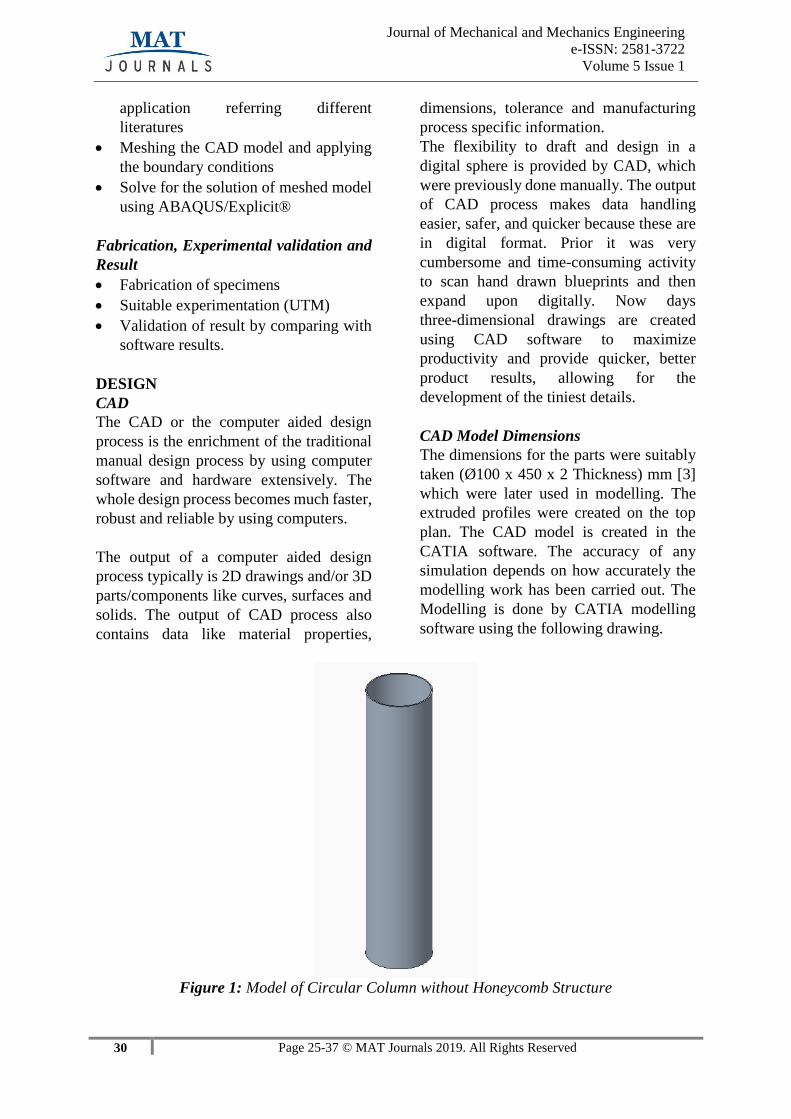
CAD Model Dimensions
The dimensions for the parts were suitably
taken (Ø100 x 450 x 2 Thickness) mm [3]
which were later used in modelling. The
extruded profiles were created on the top
plan. The CAD model is created in the
CATIA software. The accuracy of any
simulation depends on how accurately the
modelling work has been carried out. The
Modelling is done by CATIA modelling
software using the following drawing.
Figure 1: Model of Circular Column without Honeycomb Structure
31 Page 25-37 © MAT Journals 2019. All Rights Reserved
Journal of Mechanical and Mechanics Engineering
e-ISSN: 2581-3722
Volume 5 Issue 1
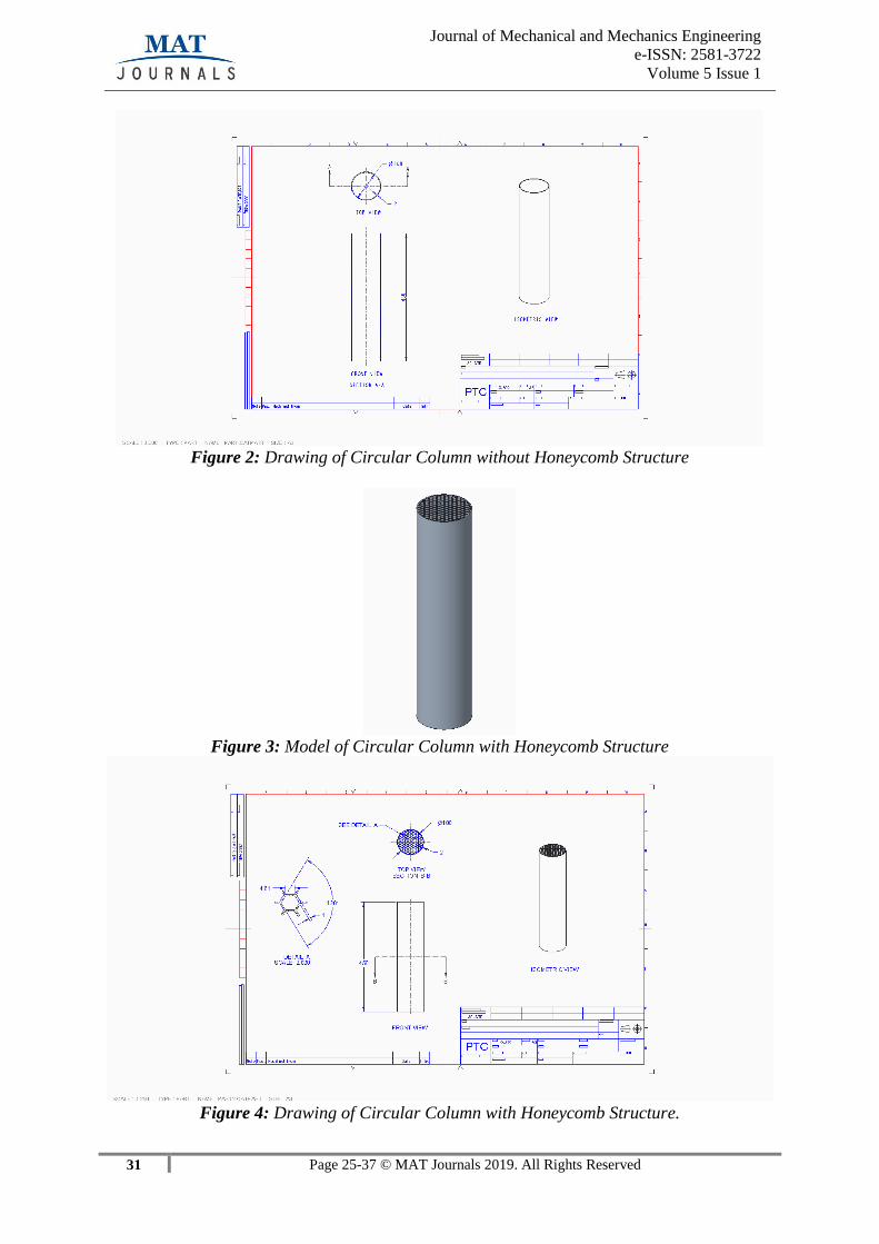
Figure 2: Drawing of Circular Column without Honeycomb Structure
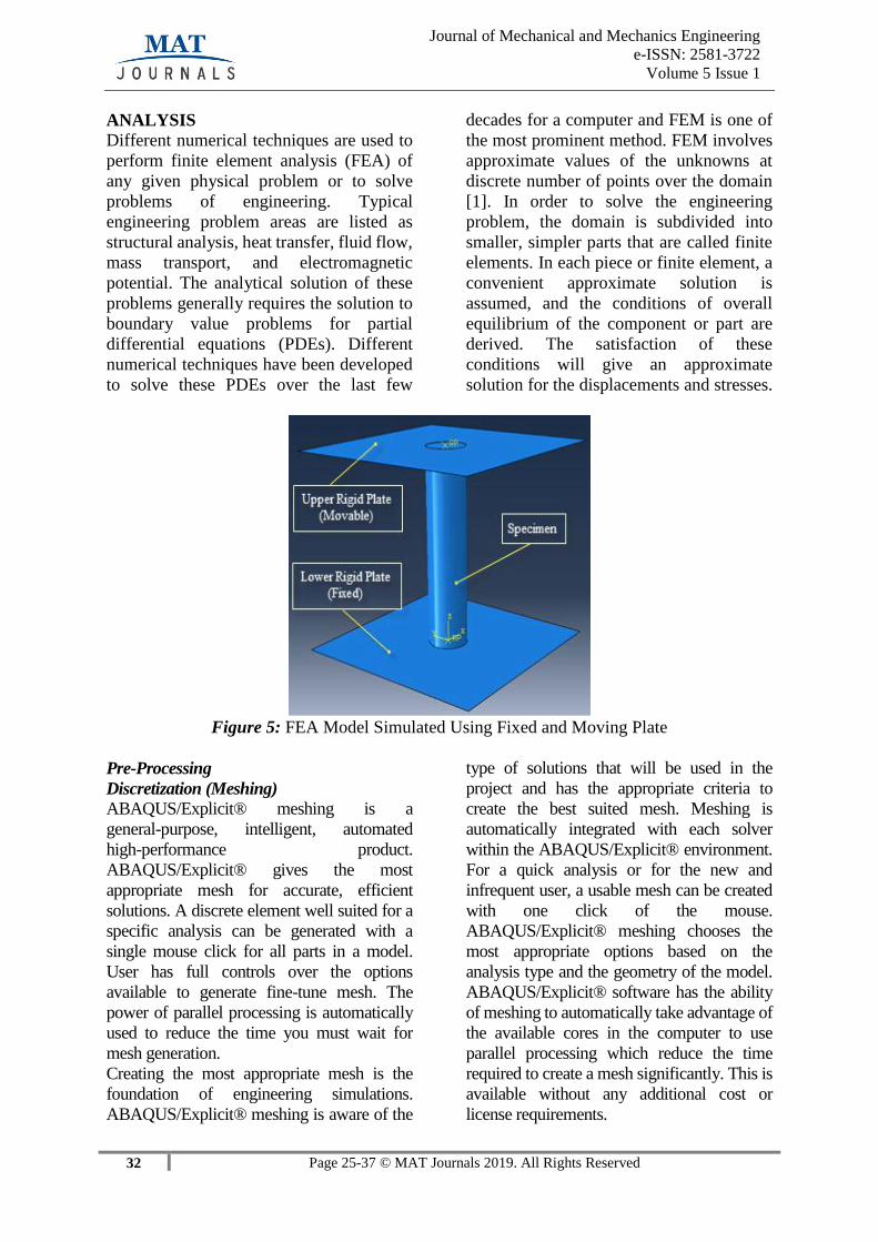
Figure 3: Model of Circular Column with Honeycomb Structure
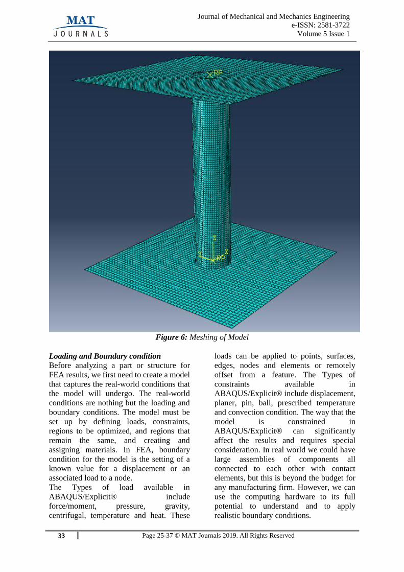
Figure 4: Drawing of Circular Column with Honeycomb Structure.
32 Page 25-37 © MAT Journals 2019. All Rights Reserved
Journal of Mechanical and Mechanics Engineering
e-ISSN: 2581-3722
Volume 5 Issue 1
ANALYSIS
Different numerical techniques are used to
perform finite element analysis (FEA) of
any given physical problem or to solve
problems of engineering. Typical
engineering problem areas are listed as
structural analysis, heat transfer, fluid flow,
mass transport, and electromagnetic
potential. The analytical solution of these
problems generally requires the solution to
boundary value problems for partial
differential equations (PDEs). Different
numerical techniques have been developed
to solve these PDEs over the last few
decades for a computer and FEM is one of
the most prominent method. FEM involves
approximate values of the unknowns at
discrete number of points over the domain
[1]. In order to solve the engineering
problem, the domain is subdivided into
smaller, simpler parts that are called finite
elements. In each piece or finite element, a
convenient approximate solution is
assumed, and the conditions of overall
equilibrium of the component or part are
derived. The satisfaction of these
conditions will give an approximate
solution for the displacements and stresses.
Figure 5: FEA Model Simulated Using Fixed and Moving Plate
Pre-Processing
Discretization (Meshing) ABAQUS/Explicit® meshing is a
general-purpose, intelligent, automated
high-performance product.
ABAQUS/Explicit® gives the most
appropriate mesh for accurate, efficient
solutions. A discrete element well suited for a
specific analysis can be generated with a
single mouse click for all parts in a model.
User has full controls over the options
available to generate fine-tune mesh. The
power of parallel processing is automatically
used to reduce the time you must wait for
mesh generation.
Creating the most appropriate mesh is the
foundation of engineering simulations.
ABAQUS/Explicit® meshing is aware of the
type of solutions that will be used in the
project and has the appropriate criteria to
create the best suited mesh. Meshing is
automatically integrated with each solver
within the ABAQUS/Explicit® environment.
For a quick analysis or for the new and
infrequent user, a usable mesh can be created
with one click of the mouse.
ABAQUS/Explicit® meshing chooses the
most appropriate options based on the
analysis type and the geometry of the model.
ABAQUS/Explicit® software has the ability
of meshing to automatically take advantage of
the available cores in the computer to use
parallel processing which reduce the time
required to create a mesh significantly. This is
available without any additional cost or
license requirements.
33 Page 25-37 © MAT Journals 2019. All Rights Reserved
Journal of Mechanical and Mechanics Engineering
e-ISSN: 2581-3722
Volume 5 Issue 1
Figure 6: Meshing of Model
Loading and Boundary condition
Before analyzing a part or structure for
FEA results, we first need to create a model
that captures the real-world conditions that
the model will undergo. The real-world
conditions are nothing but the loading and
boundary conditions. The model must be
set up by defining loads, constraints,
regions to be optimized, and regions that
remain the same, and creating and
assigning materials. In FEA, boundary
condition for the model is the setting of a
known value for a displacement or an
associated load to a node.
The Types of load available in
ABAQUS/Explicit® include
force/moment, pressure, gravity,
centrifugal, temperature and heat. These
loads can be applied to points, surfaces,
edges, nodes and elements or remotely
offset from a feature. The Types of
constraints available in
ABAQUS/Explicit® include displacement,
planer, pin, ball, prescribed temperature
and convection condition. The way that the
model is constrained in
ABAQUS/Explicit® can significantly
affect the results and requires special
consideration. In real world we could have
large assemblies of components all
connected to each other with contact
elements, but this is beyond the budget for
any manufacturing firm. However, we can
use the computing hardware to its full
potential to understand and to apply
realistic boundary conditions.

34 Page 25-37 © MAT Journals 2019. All Rights Reserved
Journal of Mechanical and Mechanics Engineering
e-ISSN: 2581-3722
Volume 5 Issue 1
Figure 7: Boundary Condition
Material Assignment
Engineering data helps to define the material
properties in the ABAQUS/Explicit®. Once
we input the properties, it can be assigned to
each of the part. The material used in this
study is Aluminium Alloy AA6063-T6 [3].
The mechanical properties for this alloy are
as follows;
Table 1: Material Properties
Post-Processing
Total Deformation
In finite element methods irrespective of
software being used, the total deformation
and directional deformation are the most
general terms. Directional deformation can
be put as the displacement of the system in
an axis or user defined direction.
Total deformation gives the overall
deformation of the systems.

35 Page 25-37 © MAT Journals 2019. All Rights Reserved
Journal of Mechanical and Mechanics Engineering
e-ISSN: 2581-3722
Volume 5 Issue 1
Figure 8: Total Deformation of Model
Equivalent Stress
Equivalent stress σe is related to the
principal stresses by the equation:
Because of its property to allows any
arbitrary three-dimensional stress state to
be represented as a single positive stress
value, equivalent stress is used in most of
the design work. Von Mises stress is a part
of the maximum equivalent stress failure
theory which is used to predict yielding in a
ductile material.
The equivalent strain εe or the Von Mises
strain is given by formula:
Where:
ν' = Effective Poisson's ratio
36 Page 25-37 © MAT Journals 2019. All Rights Reserved
Journal of Mechanical and Mechanics Engineering
e-ISSN: 2581-3722
Volume 5 Issue 1
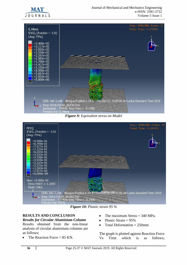
Figure 9: Equivalent stress on Model
Figure 10: Plastic strain 95 %
RESULTS AND CONCLUSION
Results for Circular Aluminium Column
Results obtained from the non-linear
analysis of circular aluminium columns are
as follows;
The Reaction Force = 85 KN.
The maximum Stress = 340 MPa.
Plastic Strain = 95%
Total Deformation = 250mm
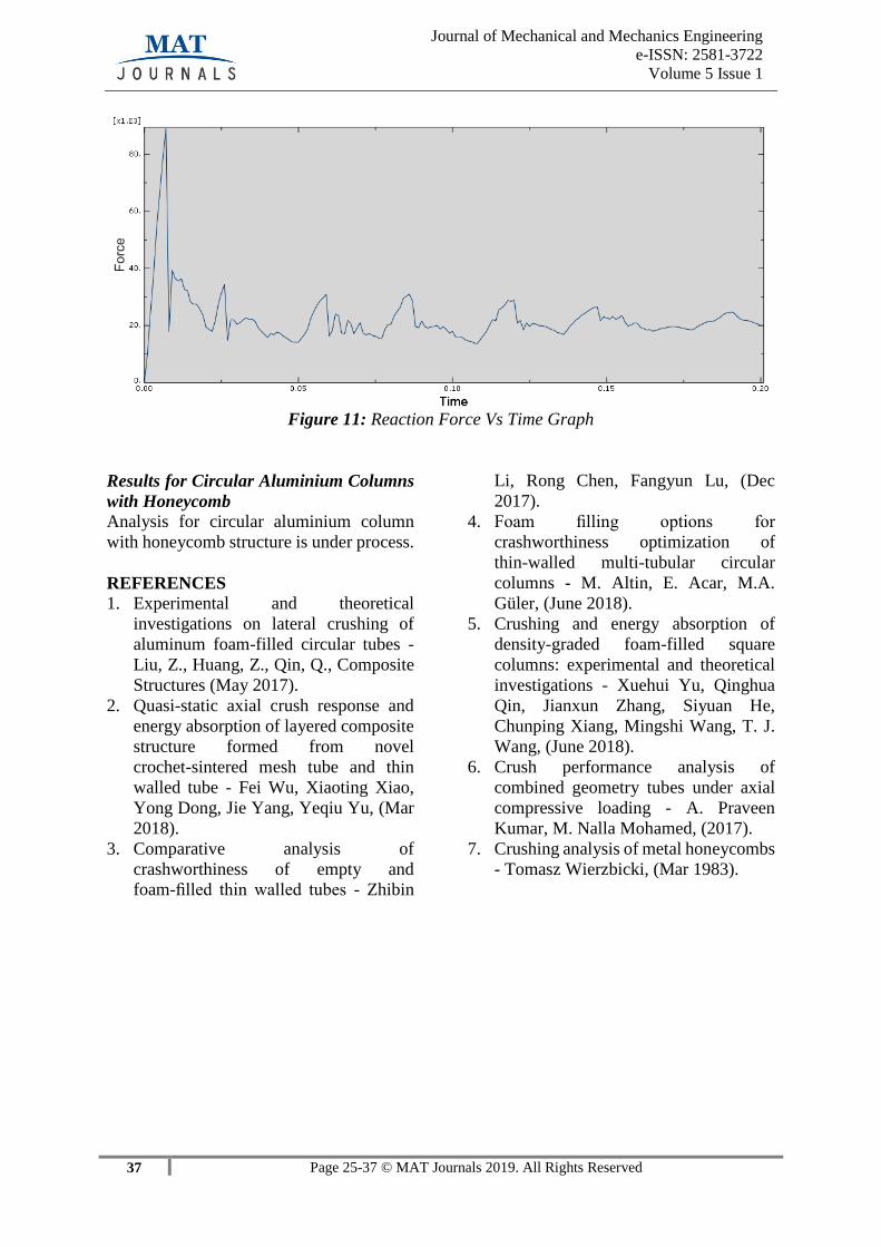
The graph is plotted against Reaction Force
Vs Time which is as follows;
37 Page 25-37 © MAT Journals 2019. All Rights Reserved
Journal of Mechanical and Mechanics Engineering
e-ISSN: 2581-3722
Volume 5 Issue 1
Figure 11: Reaction Force Vs Time Graph
Results for Circular Aluminium Columns
with Honeycomb
Analysis for circular aluminium column
with honeycomb structure is under process.
REFERENCES
1. Experimental and theoretical
investigations on lateral crushing of
aluminum foam-filled circular tubes -
Liu, Z., Huang, Z., Qin, Q., Composite
Structures (May 2017).
2. Quasi-static axial crush response and
energy absorption of layered composite
structure formed from novel
crochet-sintered mesh tube and thin
walled tube - Fei Wu, Xiaoting Xiao,
Yong Dong, Jie Yang, Yeqiu Yu, (Mar
2018).
3. Comparative analysis of
crashworthiness of empty and
foam-filled thin walled tubes - Zhibin
Li, Rong Chen, Fangyun Lu, (Dec
2017).
4. Foam filling options for
crashworthiness optimization of
thin-walled multi-tubular circular
columns - M. Altin, E. Acar, M.A.
Güler, (June 2018).
5. Crushing and energy absorption of
density-graded foam-filled square
columns: experimental and theoretical
investigations - Xuehui Yu, Qinghua
Qin, Jianxun Zhang, Siyuan He,
Chunping Xiang, Mingshi Wang, T. J.
Wang, (June 2018).
6. Crush performance analysis of
combined geometry tubes under axial
compressive loading - A. Praveen
Kumar, M. Nalla Mohamed, (2017).
7. Crushing analysis of metal honeycombs
- Tomasz Wierzbicki, (Mar 1983).