fea based comparative analysis of tube drawing processoaji.net/articles/2014/1511-1419829201.pdf ·...
TRANSCRIPT

NOVATEUR NOVATEUR NOVATEUR NOVATEUR PUBLICATIONSPUBLICATIONSPUBLICATIONSPUBLICATIONS INTERNATIONAL JOURNAL OF INNOVATIONS IN ENGINEERING RESEARCH AND TECHNOLOGY [IJIERT]INTERNATIONAL JOURNAL OF INNOVATIONS IN ENGINEERING RESEARCH AND TECHNOLOGY [IJIERT]INTERNATIONAL JOURNAL OF INNOVATIONS IN ENGINEERING RESEARCH AND TECHNOLOGY [IJIERT]INTERNATIONAL JOURNAL OF INNOVATIONS IN ENGINEERING RESEARCH AND TECHNOLOGY [IJIERT]
VOLUME 1, ISSUE 1 NOVVOLUME 1, ISSUE 1 NOVVOLUME 1, ISSUE 1 NOVVOLUME 1, ISSUE 1 NOV----2014201420142014
1 | P a g e
FEA Based comparative analysis of Tube Drawing Process
Prof. J.Y. Acharya
Department of Mechanical, Mumbai University / RSCOE, Chiplun, India [email protected]
Prof. S. Magbul Hussein
HOD, Department of Mechanical, JNTUH University / HMIT, Hyderabad, India.
Abstract Finite element analysis (FEA) simulations are extensively used in tube manipulation processes
such as tube drawing, sinking and extrusion.FEA is one of the most important methods to simulate metal
forming. This work aims to find the best geometry of die and plug to reduce the drawing force, and also
find the residual stresses in the tube using FEA. Die has been designed with different semi-die angle and
plug configurations which are all analyzed through FEA. Geometric, contact to contact surface and
material nonlinearity are involved in this problem. The material of pipe used is steel, die and plug
material used is tungsten carbide. In tube drawing, the optimum semi-die angles are identified using
FEA. In this work, the cold drawing of tubes with fixed plug was simulated by using the commercial
software Altair Hyper mesh for pre-processing and Simuilia Abacus for solving and post processing of
this study. The project intends to determine the drawing force and stress, and also helps in reducing lead
time and try outs and providing products free of defects and with controlled mechanical properties.
Keywords: Cold tube drawing, finite element analysis, die design, upper bound solution
Introduction
Superior quality products with precise dimensions, good surface finish and specified mechanical
properties can be obtained with drawing processes. The material of pipe is steel and the material of die
and the plug is tungsten carbide. The friction between the outer surface of the tube and the die and
between the inner surface of the tube and the plug has been modelled by Coulomb friction. Besides, the
change in the diameter of the tube has been considered negligible during the process, then, the forming
process can be assumed that it is made under a state of plane strain condition. After the analysis we are
able to know the force required to draw a tube, the stress distribution
In this study, we present a tool device specially designed to reduce drawn force, formed by two
dies assembled within a recipient which can be sealed, generating a pressurized lubrication during the
process. Die and plug geometry are obtained from the numerical simulation. Experimental tests with this
tooling in a laboratory drawing bench were performed, using three different lubricants and pressurized
and unpressurized lubrication. The experimental results were compared to numerical results and the
performance of the process was analyzed with a statistical model.
Nomenclature Ri = external inlet radius of the tube
Rii = internal inlet radius of the tube
Rf = external outlet radius of the tube
Rf = internal outlet radius of the tube
L = bearing length
Wh = Homogeneous work
Wr = redundant work

NOVATEUR NOVATEUR NOVATEUR NOVATEUR PUBLICATIONSPUBLICATIONSPUBLICATIONSPUBLICATIONS INTERNATIONAL JOURNAL OF INNOVATIONS IN ENGINEERING RESEARCH AND TECHNOLOGY [IJIERT]INTERNATIONAL JOURNAL OF INNOVATIONS IN ENGINEERING RESEARCH AND TECHNOLOGY [IJIERT]INTERNATIONAL JOURNAL OF INNOVATIONS IN ENGINEERING RESEARCH AND TECHNOLOGY [IJIERT]INTERNATIONAL JOURNAL OF INNOVATIONS IN ENGINEERING RESEARCH AND TECHNOLOGY [IJIERT]
VOLUME 1, ISSUE 1 NOVVOLUME 1, ISSUE 1 NOVVOLUME 1, ISSUE 1 NOVVOLUME 1, ISSUE 1 NOV----2014201420142014
2 | P a g e
Wa = friction work
Greek Symbols a = die semi-angle
ap = plug semi-angle
dp = nib diameter
b = semi-angle of the internal cone of the tube after drawing without plug
e = true strain
m1 = Coulomb friction between tube and die
m2 = Coulomb friction between plug and tube
s = stress
stref =drawing stress
s0 = average yield stress
t1 = Velocity surface discontinuity on inner die
t2 = Velocity surface discontinuity on outer die
t3 = Contact surface in the work zone at die/work piece interface
t4 = Contact surface in the die bearing/work piece interface
t5 = Contact surface in the plug bearing/work piece interface
t6 = contact surface in the work at zone plug/work piece interface
Plug Geometry
Fig. 1 Plug geometry and CAD model
Plug geometry is shown in Fig. 1. The region A is a cylindrical portion to position the plug inside the
die. Its diameter is slightly smaller than the tube inner diameter. The plug semi-angle (ap) in the work
zone B is smaller than die semi-angle (a). It is defined to be 2 degrees or smaller than die semi-angle.
Region C, called ‘nib’, is cylindrical and controls the inner diameter of the tube. In the present study the
wall thickness of the tube was reduced by 0.1 mm. The length of the nib was fixed in 2 mm for all tests.
[1]
Finite Element Model

NOVATEUR NOVATEUR NOVATEUR NOVATEUR PUBLICATIONSPUBLICATIONSPUBLICATIONSPUBLICATIONS INTERNATIONAL JOURNAL OF INNOVATIONS IN ENGINEERING RESEARCH AND TECHNOLOGY [IJIERT]INTERNATIONAL JOURNAL OF INNOVATIONS IN ENGINEERING RESEARCH AND TECHNOLOGY [IJIERT]INTERNATIONAL JOURNAL OF INNOVATIONS IN ENGINEERING RESEARCH AND TECHNOLOGY [IJIERT]INTERNATIONAL JOURNAL OF INNOVATIONS IN ENGINEERING RESEARCH AND TECHNOLOGY [IJIERT]
VOLUME 1, ISSUE 1 NOVVOLUME 1, ISSUE 1 NOVVOLUME 1, ISSUE 1 NOVVOLUME 1, ISSUE 1 NOV----2014201420142014
3 | P a g e
Fig 2. The geometry of the plug.
The outer diameter of the plug is 210mm. The plug is cylindrical in shape. The material of the plug used
is tungsten carbide. The figure 2 shows the geometry of the tube. The initial outer diameter & inner
diameter of tube are 273 mm & 223 respectively. After the tube is been processed the final dimensions
of the tube will be outer diameter = 260mm, and inner diameter = 210mm and the length is 700mm.The
material of the tube used is steel. The figure 2 shows the geometry of the die. The die material used is
tungsten carbide. The outer diameter of the die is 360mm, inner diameter is mm. The die consists of a
semi die angle (6, 7, and 8). The figures 2 show the assembly of the plug, tube and the die as in the
process. The figure 2 shows the section of the assembly which makes it convenient to carry out the
analysis. An elasto-plastic model was used for the material of the tube. Tensile tests of stainless A304
steel tubes were carried out to obtain the stress-strain curve (s x e) to be used in the simulation. This
stress-strain curve was approached by Holloman’s equation as shown in Eq. (1).
s = 1137 e0,52 [MPa] (1)
Young modulus of 210 GPa and a Poisson ratio of 0.3 were defined to the tube material, which
was assumed to be isotropic and insensitive to strain rate. During experimental drawing it was noticed
that the temperature at the tube was not higher than 100 ºC, thus allowing the tube material to be
modeled independent on the temperature.
Experimental Design To evaluate the drawing force, a random factorial analysis was designed with the following variables:
- Lubricants: commercial mineral oil, semi-synthetic oil, and mineral oil with extreme pressure
additives;
- Drawing speed: 1 m/min; 2 m/min and 5 m/min;
- Lubrication: Pressurized and not-pressurized.
FEM Analysis PROCESS PARAMETERS
The process variables are:
1. Initial Dimensions of the pipe
• Outer diameter: 273 mm
• Inner diameter: 223 mm
• Length of pipe: 700 mm.
• Thickness: 13 mm
2. Final dimensions of pipe
• Outer diameter: 260 mm

INTERNATIONAL JOURNAL OF INNOVATIONS IN ENGINEERING RESEARCH AND TECHNOLOGY [IJIERT]INTERNATIONAL JOURNAL OF INNOVATIONS IN ENGINEERING RESEARCH AND TECHNOLOGY [IJIERT]INTERNATIONAL JOURNAL OF INNOVATIONS IN ENGINEERING RESEARCH AND TECHNOLOGY [IJIERT]INTERNATIONAL JOURNAL OF INNOVATIONS IN ENGINEERING RESEARCH AND TECHNOLOGY [IJIERT]
• Inner diameter: 210 mm
• Thickness: 13 mm
3. Dimensions of die.
• Semi die angle: 6, 7, 8
• Outer diameter: 360 mm
• Inner diameter: 260 mm
4. Dimensions of plug.
• Outer diameter: 210 mm
5. Co efficient of friction.
• 0.
• 0.05.
• 0.1.
• 0.15.
• 0.2.
MATERIALS SPECIFICATION
Units Used Geometry— in mm
Density——Ton/mm3
Stress —— MPa
Force —— N
Mechanical Properties Tensile Strength, Ultimate: 745 MPa
Tensile Strength, Yield : 470 MPa
Modulus of Elasticity : 210000 MPa
Bulk Modulus : 140000 MPa
Poisson’s Ratio : 0.30
All Dimensions in mm
After completion of preparation of Finite Element model i.e., preparation of CAD model,
meshing & applying boundary condition a solvers’ work begins. The finite element model from the
Hyper Mesh (.INP file) is exported to the Simulia Abaqus software as an input file to run the analysis.
Abaqus viewer software is used to view the results.
semi angle 6, 7, 8 at various frictions (0, 0.05, 0.1, 0.15,
INTERNATIONAL JOURNAL OF INNOVATIONS IN ENGINEERING RESEARCH AND TECHNOLOGY [IJIERT]INTERNATIONAL JOURNAL OF INNOVATIONS IN ENGINEERING RESEARCH AND TECHNOLOGY [IJIERT]INTERNATIONAL JOURNAL OF INNOVATIONS IN ENGINEERING RESEARCH AND TECHNOLOGY [IJIERT]INTERNATIONAL JOURNAL OF INNOVATIONS IN ENGINEERING RESEARCH AND TECHNOLOGY [IJIERT]VOLUME 1, ISSUE 1 NOVVOLUME 1, ISSUE 1 NOVVOLUME 1, ISSUE 1 NOVVOLUME 1, ISSUE 1 NOV
Inner diameter: 210 mm
Semi die angle: 6, 7, 8
Outer diameter: 360 mm
Inner diameter: 260 mm
Outer diameter: 210 mm
MATERIALS SPECIFICATION
Table no.1: Materials properties
745 MPa
: 470 MPa
: 210000 MPa
: 140000 MPa
After completion of preparation of Finite Element model i.e., preparation of CAD model,
meshing & applying boundary condition a solvers’ work begins. The finite element model from the
(.INP file) is exported to the Simulia Abaqus software as an input file to run the analysis.
Abaqus viewer software is used to view the results. The analysis is carried out for a combination die
semi angle 6, 7, 8 at various frictions (0, 0.05, 0.1, 0.15, 0.2), and then the stress and drawing force
NOVATEUR NOVATEUR NOVATEUR NOVATEUR PUBLICATIONSPUBLICATIONSPUBLICATIONSPUBLICATIONS INTERNATIONAL JOURNAL OF INNOVATIONS IN ENGINEERING RESEARCH AND TECHNOLOGY [IJIERT]INTERNATIONAL JOURNAL OF INNOVATIONS IN ENGINEERING RESEARCH AND TECHNOLOGY [IJIERT]INTERNATIONAL JOURNAL OF INNOVATIONS IN ENGINEERING RESEARCH AND TECHNOLOGY [IJIERT]INTERNATIONAL JOURNAL OF INNOVATIONS IN ENGINEERING RESEARCH AND TECHNOLOGY [IJIERT]
VOLUME 1, ISSUE 1 NOVVOLUME 1, ISSUE 1 NOVVOLUME 1, ISSUE 1 NOVVOLUME 1, ISSUE 1 NOV----2014201420142014
4 | P a g e
After completion of preparation of Finite Element model i.e., preparation of CAD model,
meshing & applying boundary condition a solvers’ work begins. The finite element model from the
(.INP file) is exported to the Simulia Abaqus software as an input file to run the analysis.
The analysis is carried out for a combination die
0.2), and then the stress and drawing force

NOVATEUR NOVATEUR NOVATEUR NOVATEUR PUBLICATIONSPUBLICATIONSPUBLICATIONSPUBLICATIONS INTERNATIONAL JOURNAL OF INNOVATIONS IN ENGINEERING RESEARCH AND TECHNOLOGY [IJIERT]INTERNATIONAL JOURNAL OF INNOVATIONS IN ENGINEERING RESEARCH AND TECHNOLOGY [IJIERT]INTERNATIONAL JOURNAL OF INNOVATIONS IN ENGINEERING RESEARCH AND TECHNOLOGY [IJIERT]INTERNATIONAL JOURNAL OF INNOVATIONS IN ENGINEERING RESEARCH AND TECHNOLOGY [IJIERT]
VOLUME 1, ISSUE 1 NOVVOLUME 1, ISSUE 1 NOVVOLUME 1, ISSUE 1 NOVVOLUME 1, ISSUE 1 NOV----2014201420142014
5 | P a g e
obtained from the analysis for die semi angle 6, 7, 8 are compared and the optimized values of them are
chosen for best geometry which reduces lead time and try outs and providing products free of defects
and with controlled mechanical properties.
CASE 1: Die semi angle 6 Degree and Friction (0, 0.05, 0.1, 0.15, 0.2)
1. Friction 0
Figure 3.1: Initial step at 6 degree and friction 0 Figure 3.2: Final step at 6 degree and friction 0
2. Friction 0.05
Figure 3.3: Initial step at 6 degree and friction 0.05Figure 3.4: Final step at 6 degree and friction 0.05
3. Friction 0.1
Figure35: Initial step at 6 degree and friction 0.1Figure 3.6: Final step at 6 degree and friction 0.1
4. Friction 0.15

NOVATEUR NOVATEUR NOVATEUR NOVATEUR PUBLICATIONSPUBLICATIONSPUBLICATIONSPUBLICATIONS INTERNATIONAL JOURNAL OF INNOVATIONS IN ENGINEERING RESEARCH AND TECHNOLOGY [IJIERT]INTERNATIONAL JOURNAL OF INNOVATIONS IN ENGINEERING RESEARCH AND TECHNOLOGY [IJIERT]INTERNATIONAL JOURNAL OF INNOVATIONS IN ENGINEERING RESEARCH AND TECHNOLOGY [IJIERT]INTERNATIONAL JOURNAL OF INNOVATIONS IN ENGINEERING RESEARCH AND TECHNOLOGY [IJIERT]
VOLUME 1, ISSUE 1 NOVVOLUME 1, ISSUE 1 NOVVOLUME 1, ISSUE 1 NOVVOLUME 1, ISSUE 1 NOV----2014201420142014
6 | P a g e
Figure 3.7: Initial step at 6 degree and friction 0.15Figure3.8: Final step at 6 degree and friction 0.15
5. Friction 0.2
Figure 3.9: Initial step at 6 degree and friction 0.2Figure 3.10: Final step at 6 degree and friction 0.2
RESULT OF CASE 1: The below graph of stress and drawing force are obtained from the above analysis of
model at die semi angle of 6 degrees and friction (0, 0.05, 0.1, 0.15, 0.2).
Figure 3.11: Stress graph for case 1 Figure 3.12: Drawing Force graph for case 1
CASE 2: Die semi angle 7 Degree and Friction (0, 0.05, 0.1, 0.15, 0.2)
1. Friction 0
0
50
100
150
200
250
0 0.1 0.2 0.3
Str
ess
(M
Pa
)
Friction
STRESS
STRESS
0
1000
2000
3000
4000
5000
0 0.1 0.2 0.3
Dra
win
g F
orc
e (K
N)
Friction
DRAWING FORCE
DRAWING
FORCE

NOVATEUR NOVATEUR NOVATEUR NOVATEUR PUBLICATIONSPUBLICATIONSPUBLICATIONSPUBLICATIONS INTERNATIONAL JOURNAL OF INNOVATIONS IN ENGINEERING RESEARCH AND TECHNOLOGY [IJIERT]INTERNATIONAL JOURNAL OF INNOVATIONS IN ENGINEERING RESEARCH AND TECHNOLOGY [IJIERT]INTERNATIONAL JOURNAL OF INNOVATIONS IN ENGINEERING RESEARCH AND TECHNOLOGY [IJIERT]INTERNATIONAL JOURNAL OF INNOVATIONS IN ENGINEERING RESEARCH AND TECHNOLOGY [IJIERT]
VOLUME 1, ISSUE 1 NOVVOLUME 1, ISSUE 1 NOVVOLUME 1, ISSUE 1 NOVVOLUME 1, ISSUE 1 NOV----2014201420142014
7 | P a g e
Figure 3.13: Initial step at 7 degree and friction 0Figure3.14: Final step at 7 degree and friction 0
2. Friction 0.05
Figure 3.15: Initial step at 7 degree and friction 0.05Figure 3.16: Final step at 7 degree and friction 0.05
3. Friction 0.1
Figure 3.17: Initial step at 7 degree and friction 0.1Figure 3.18: Final step at 7 degree and friction 0.1
4. Friction 0.15

NOVATEUR NOVATEUR NOVATEUR NOVATEUR PUBLICATIONSPUBLICATIONSPUBLICATIONSPUBLICATIONS INTERNATIONAL JOURNAL OF INNOVATIONS IN ENGINEERING RESEARCH AND TECHNOLOGY [IJIERT]INTERNATIONAL JOURNAL OF INNOVATIONS IN ENGINEERING RESEARCH AND TECHNOLOGY [IJIERT]INTERNATIONAL JOURNAL OF INNOVATIONS IN ENGINEERING RESEARCH AND TECHNOLOGY [IJIERT]INTERNATIONAL JOURNAL OF INNOVATIONS IN ENGINEERING RESEARCH AND TECHNOLOGY [IJIERT]
VOLUME 1, ISSUE 1 NOVVOLUME 1, ISSUE 1 NOVVOLUME 1, ISSUE 1 NOVVOLUME 1, ISSUE 1 NOV----2014201420142014
8 | P a g e
Figure 3.19: Initial step at 7 degree and friction 0.15Figure 3.20: Final step at 7 degree and friction 0.15
5. Friction 0.2
Figure 3.21: Initial step at 7 degree and friction 0.2Figure 3.22: Final step at 7 degree and friction 0.2
RESULT OF CASE 2: The below graph of stress and drawing force are obtained from the above analysis of
model at die semi angle of 7 degrees and friction (0, 0.05, 0.1, 0.15, 0.2).
Figure 3.23: Stress graph for case 2 Figure 3.24: Drawing Force graph for case 2
CASE 3: Die semi angle 8 Degree and Friction (0, 0.05, 0.1, 0.15, 0.2)
1. Friction 0
0
50
100
150
200
250
0 0.1 0.2 0.3
Str
ess
(MP
a)
Friction
STRESS
STRESS
0
1000
2000
3000
4000
5000
0 0.1 0.2 0.3
Dra
win
g f
orc
e (K
N)
Friction
DRAWING FORCE
DRAWING
FORCE
NOVATEUR NOVATEUR NOVATEUR NOVATEUR PUBLICATIONSPUBLICATIONSPUBLICATIONSPUBLICATIONS INTERNATIONAL JOURNAL OF INNOVATIONS IN ENGINEERING RESEARCH AND TECHNOLOGY [IJIERT]INTERNATIONAL JOURNAL OF INNOVATIONS IN ENGINEERING RESEARCH AND TECHNOLOGY [IJIERT]INTERNATIONAL JOURNAL OF INNOVATIONS IN ENGINEERING RESEARCH AND TECHNOLOGY [IJIERT]INTERNATIONAL JOURNAL OF INNOVATIONS IN ENGINEERING RESEARCH AND TECHNOLOGY [IJIERT]
VOLUME 1, ISSUE 1 NOVVOLUME 1, ISSUE 1 NOVVOLUME 1, ISSUE 1 NOVVOLUME 1, ISSUE 1 NOV----2014201420142014
9 | P a g e
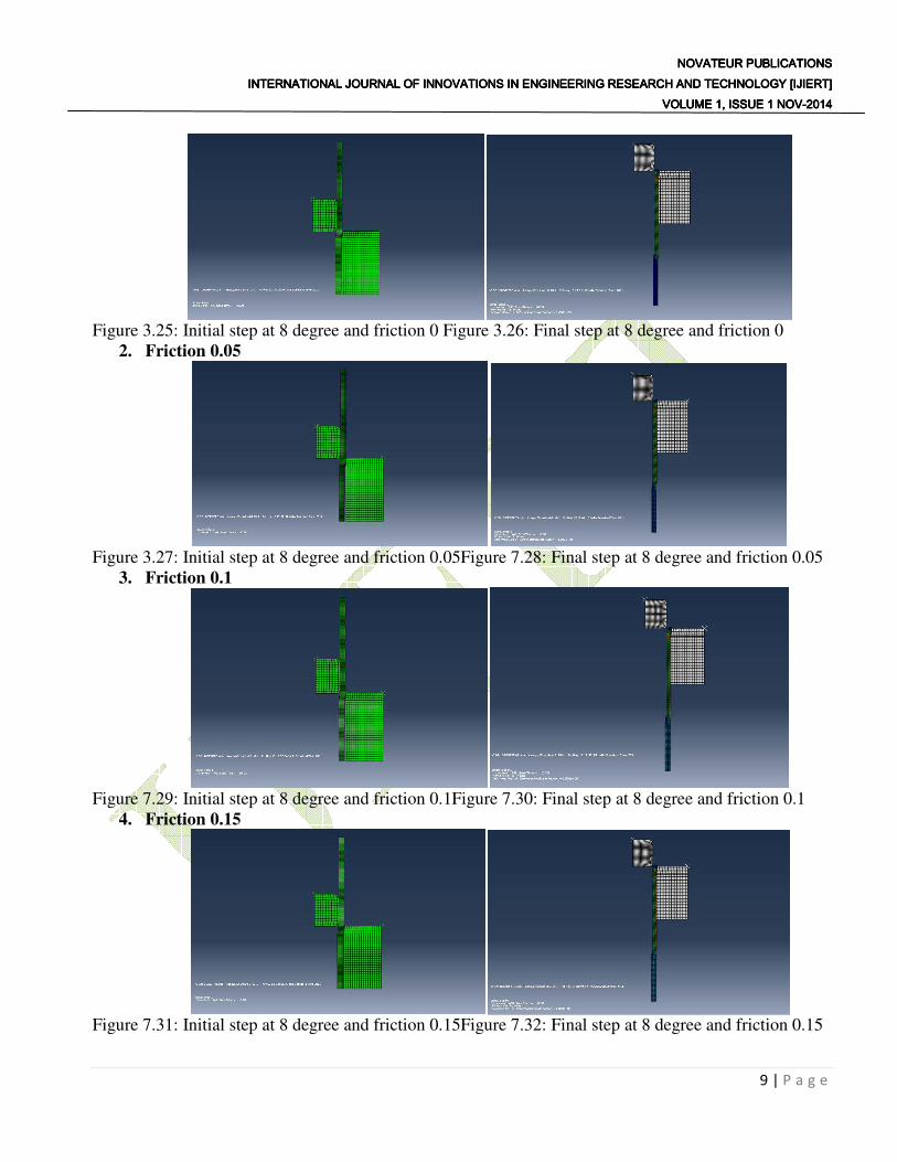
Figure 3.25: Initial step at 8 degree and friction 0 Figure 3.26: Final step at 8 degree and friction 0
2. Friction 0.05
Figure 3.27: Initial step at 8 degree and friction 0.05Figure 7.28: Final step at 8 degree and friction 0.05
3. Friction 0.1
Figure 7.29: Initial step at 8 degree and friction 0.1Figure 7.30: Final step at 8 degree and friction 0.1
4. Friction 0.15
Figure 7.31: Initial step at 8 degree and friction 0.15Figure 7.32: Final step at 8 degree and friction 0.15

NOVATEUR NOVATEUR NOVATEUR NOVATEUR PUBLICATIONSPUBLICATIONSPUBLICATIONSPUBLICATIONS INTERNATIONAL JOURNAL OF INNOVATIONS IN ENGINEERING RESEARCH AND TECHNOLOGY [IJIERT]INTERNATIONAL JOURNAL OF INNOVATIONS IN ENGINEERING RESEARCH AND TECHNOLOGY [IJIERT]INTERNATIONAL JOURNAL OF INNOVATIONS IN ENGINEERING RESEARCH AND TECHNOLOGY [IJIERT]INTERNATIONAL JOURNAL OF INNOVATIONS IN ENGINEERING RESEARCH AND TECHNOLOGY [IJIERT]
VOLUME 1, ISSUE 1 NOVVOLUME 1, ISSUE 1 NOVVOLUME 1, ISSUE 1 NOVVOLUME 1, ISSUE 1 NOV----2014201420142014
10 | P a g e
5. Friction 0.2
Figure 7.33: Initial step at 8 degree and friction 0.2Figure 7.34: Final step at 8 degree and friction 0.2
RESULT OF CASE 3: The below graph of stress and drawing force are obtained from the above
analysis of model at die semi angle of 8 degrees and friction (0, 0.05, 0.1, 0.15, 0.2).
Figure 3.35: Stress graph for case 3 Figure 3.36: Drawing Force graph for case 3
Conclusions The main objective of the project work is to determine the optimum drawing force and stress for
the tube drawing process. After completing the analysis for combination of friction and different die
geometry, the results obtained are compared to find out the optimum drawing force and stress to produce
a tube with a best geometry. After comparing all the 3 cases in graphs shown below, it is found that the
case 3 with die geometry i.e. semi die angle 8 is found optimum for drawing a tube of outer diameter
260mm and inner diameter of 210mm. The optimum drawing force and the stress found for die
geometry of semi die angle are respectively 2218.5 KN and 113.87 MPa.
0
50
100
150
0 0.2 0.4
Str
ess
(MP
a)
Friction
STRESS
STRESS 0
1000
2000
3000
0 0.1 0.2 0.3
Dra
win
g F
orc
e(K
N)
Friction
DRAWING FORCE
DRAWING
FORCE

NOVATEUR NOVATEUR NOVATEUR NOVATEUR PUBLICATIONSPUBLICATIONSPUBLICATIONSPUBLICATIONS INTERNATIONAL JOURNAL OF INNOVATIONS IN ENGINEERING RESEARCH AND TECHNOLOGY [IJIERT]INTERNATIONAL JOURNAL OF INNOVATIONS IN ENGINEERING RESEARCH AND TECHNOLOGY [IJIERT]INTERNATIONAL JOURNAL OF INNOVATIONS IN ENGINEERING RESEARCH AND TECHNOLOGY [IJIERT]INTERNATIONAL JOURNAL OF INNOVATIONS IN ENGINEERING RESEARCH AND TECHNOLOGY [IJIERT]
VOLUME 1, ISSUE 1 NOVVOLUME 1, ISSUE 1 NOVVOLUME 1, ISSUE 1 NOVVOLUME 1, ISSUE 1 NOV----2014201420142014
11 | P a g e
Figure 4.1 Comparison of stress. Figure 4.2: Comparison of the drawing force.
References
[1]S.T.Button, C.Caminaga and F.C.Gentile, Numerical and Experimental and analysis of tube
drawing with fixed plug.
[2]E.M.Rubio, Analytical methods application to the study of tube drawing process with fixed
conical inner plug.
[3]C.S.Wang and Y.C.Wang, The theoretical and experimental of tube drawing with floating plug
for micro heat-pipes, R.O.C.
[4]George.E.Dieter, Mechanical Metallurgy, McGraw-HILL Book Company. Chapter 15 pg no
518, Chapter 19 pg no 650.
[5]Heinz Tschaetsch, Metal Forming Practise Springer, Chapter 11 pg no 105.
[6]Nitin.S.Gokhale, Sanjay.S.Deshpande, Sanjeev.V.Bedekar, Anand.N.Thite.Practical Finite
Element Analysis.
0
50
100
150
200
250
0 0.2 0.4
Str
ess(
MP
a)
Friction
Chart Title
Stress for 6
degree
Stress for 7
degree
Stress for 8
degree
0
1000
2000
3000
4000
5000
0 0.1 0.2 0.3
Dra
win
g F
prc
e (K
N)
Friction
Chart Title
Drawing
force for 6
degree
Drawing
force for 7
degree
Drawing
force for 8
degree