fea of the blast loading effect on ships hull
TRANSCRIPT

Ocean Systems Engineering, Vol. 1, No. 3 (2011) 223-239 223
FEA of the blast loading effect on ships hull
Muhsin Hamdoon*1, Nader Zamani1 and Sreekanta Das2
1Dept. of Mechanical, Automotive, and Materials Engineering, University of Windsor, Windsor, Canada 2Dept. of Civil and Environmental Engineering, University of Windsor, Windsor, Canada
(Received April 14, 2011, Revised August 31, 2011, Accepted September 3, 2011)
Abstract. In combat operations, naval ships may be subjected to considerable air blast and underwatershock loads capable of causing severe structural damage. As the experimental study imposes greatmonetary and time cost, the numerical solution may provide a valuable alternative. This study emphasiseson numerical analysis for optimization of stiffened and unstiffened plate’s structural response subjected toair blast load. Linear and non linear finite element (FE) modeling and analysis was carried out andcompared with existing experimental results. The obtained results reveal a good agreement betweennumerical and experimental observations. The presented FE models can eliminate confusion regardingparameters selection and FE operations processing, using commercial software available currently.
Keywords: stiffened/unstiffened plate; blast loading; ship hull; dynamic response; Explicit/Implicitschemes.
1. Introduction
Steel members such as I-beam, angle, channel, and other sections are usually connected to steel
plates to build stiffened steel plates. Stiffened and unstiffened steel plates are used in ship hulls and
decks as well as many other structural applications such as bridge plate girders and offshore
platforms. In modern warfare, naval ships could be subjected to considerable air blast and
underwater shock loads. Blast load is a very high load mode applied within short time period in
pressure form to structures as a result of explosions. For effective warship design against air blast
and underwater shock threats, a fundamental and detailed understanding of shock wave loading and
the associated structural response is required. In this study, the FEA results are compared with the
experimental data found by the Defence Research Establishment Suffield (DRES) in Canada. The
commercial software utilized in this study provided sufficient features in the numerical analysis. In
the same time, comparison between FE and experimental results proofed the targeted software
consistency to this type of problems.
There is a considerable literature for this research area may be reported here starting by Houlston
and Slater work (Houlston and Slater 1985a, b, 1991, 1993). Houlston and Slater conducted twelve
tests on square unstiffened plates experimentally and published the data of two of them (1 and 4).
Test 1 was analysed statically and dynamically, while Test 4 analysed dynamically. Subsequently,
they carried out numerical analyses using ADINA software.
*Corresponding author, PhD candidate, E-mail: [email protected]
DOI: http://dx.doi.org/10.12989/ose.2011.1.3.223

224 Muhsin Hamdoon, Nader Zamani and Sreekanta Das
For test 4, the displacements obtained from the finite element calculations are quite consistent to
that of the experimental study. The sensitivity of the plate center displacement to variation in the
boundary conditions was also considered. They found that some improvement can be obtained by
relaxing the requirement of fully fixed boundary conditions. Allowing tangential rotation (or simply
supported boundary conditions) leads to some improvement in the correlation of peak amplitudes
(of the FE models) with experimental results but the correlation of other detail is made worse.
Allowing slip to occur at the boundary gives some improvement in the period of response. When
both normal slip and tangential rotation are allowed, the improvement in amplitude is retained but
the period becomes too large. It thus appears that some combination of slip and rotation on the plate
boundaries may achieve an improved correlation.
Houlston and Slater also conducted an experimental and numerical analysis on three stiffened
plates. In addition to the stiffened panels tested experimentally at DRES, a stiffened panel (Panel 4)
was tested at the U.S. Defence Nuclear Agency’s event code entitled “MINOR SCALE”.
Later, Houlston and Slater created four different FE models using a variety of boundary
conditions for the square plate (unstiffened). They observed a close displacement-time relation to
the experimental curve in case of the FE model which includes plane movement of the plate portion
under square mounting ring. The clamping in this case is associated only to the bolts holes. For
stiffened panel, the authors found that loading velocity has a significant effect on the FEA results as
well as the boundary conditions (Houlston and Slater 1991).
Houlston and Slater also utilised the computational fluid dynamics (CFD) methods to analyse the
non-linear dynamic air blast load. Subsequently, they used computational structural dynamics (CSD)
for analysis of non-linear structural response of the plate (Houlston and Slater 1993).
Cichocki and Ruchwa utilised the experimental results of stiffened panels tests which conducted
by Houlston and Slater. The study considered three FE models: the first is elastoplastic according to
von-Mises, while the two other models are according to Johnson-cook (JC) material model. The
difference between those JC models is that one of them (JC1) assumes spatially uniform load
distribution (the field of pressure is a function of time, not space), and the another model (JC2) is
taking into account the wave propagation across the panel. The researchers plotted displacement-
time relationship of the mid-point of plate and mid-span of the I-beam. Their observations indicate
that the closest FE displacement curve to the experimental one was obtained in case of JC2 (spatial
distribution of load). They justified this observation as a result of relatively slow propagation of the
blast load in air, so there is a delay in arrival of the blast wave to different points of the panel
(Cichocki and Ruchwa 2000).
Kadid carried out a numerical analysis to examine the behaviour of stiffened and unstiffened
plates subjected to uniform blast loading. The aim of his work is to determine the dynamic response
of the plates with different stiffener configurations and consider the effect of mesh dependency,
loading duration, and strain-rate sensitivity. The results obtained indicate that stiffener configurations
and time duration can affect the overall plate behaviour (Kadid 2008).
Turkmen and Mecitoglu performed an experimental and numerical study of stiffened laminated
composite plates exposed to a normal blast shock wave. An agreement is found between the
experimental and finite element results in both linear and nonlinear ranges. However a discrepancy
is shown between the measured and predicted strains on the stiffener because of the adhesive layer
between the plate and stiffener. The blast pressure measurements on the plate show that the
character of the pressure variation is strongly dependent on the distance from the open end of the
tube to the target plate. For example, if this distance is decreased about three times, the peak

FEA of the blast loading effect on ships hull 225
pressure on the plate increases in scale of ten times (Turkmen and Mecitoglu 1999).
2. Experimental test procedure
The experimental apparatus and procedure are carried out by the Defence Research Establishment
Suffield (DRES), in two different facilities. The first facility consists of concrete room of dimensions
(6.1 × 6.1 × 6.1 m) with reinforced concrete walls, floor and ceiling as shown in Fig. 1(a). Charge is
limited to a maximum of (1 kg) of high explosive. This size restriction limited the blast loading to
about (700 kPa) at (2 m) standoff. The first test series of square plate (unstiffened) was conducted
utilising this facility.
The second facility is the Height-of-Burst Site which consists of two towers connected to cables. The
charge of (14.5 kg) was suspended by cables at height of (2.4 m) and (3.1 m), as shown in Fig. 1(b).
The second test series of square plate (unstiffened) and all of the stiffened panel’s tests were carried
out by this method.
2.1 Unstiffened plate
The plate has dimensions of (508 × 508 mm) with thickness of (3.4 mm) and made of steel. The
steel has Young’s modulus of (207 GPa), Poisson’s ratio of (0.3) and mass density of (7770 kg/m3).
The yield strength is equal to (345 MPa) and the tangent modulus of (68.9 MPa). The plates were
positioned on a special plate mounting system shown in Fig. 2 which was designed to achieve fully
clamped boundary conditions and to reduce effects of reflected shock. The connection between the
target plate and the support box beams was conducted using bolts. Four pressure transducers (Pl-P4)
were mounted around the periphery of each plate to capture pressure produced by explosion. Each
test consisted of detonating a charge suspended directly above the center of the plate at a known
standoff distance. The maximum pressure produced is (172 kPa) and varies over time period of
(8 ms) as shown in Fig. 3 after shifted and averaged. The shifting and averaging were implemented
to compensate the difference in arrival times of the pressure signals. Six accelerometers (A1-A6)
were attached to the surface of the upper right quarter of the plate to record the acceleration during
test period. The recorded acceleration was integrated twice to obtain displacement of the plate in the
direction of pressure applied.
Fig. 1 Blast Facilities (re-sketched incorporating reference #2)

226 Muhsin Hamdoon, Nader Zamani and Sreekanta Das
2.2 Stiffened panel
The dimensions of the stiffened panel of “MINOR SCALE” (which presented by the U.S.
Defence Nuclear Agency’s event code) were (5.131 × 3.454 m) with thickness of (6.35 mm) and the
net dimensions between supports were (4.572 × 2.438 m). The four (76 × 152 mm) I-beams divided
the panel to five equal area bays of (2.438 × 0.914 m) each, as shown in Fig. 4. The plate is made
of steel which has properties as follows: Young’s modulus of (207 GPa), Poisson’s ratio of (0.3),
dynamic yield stress of (375 MPa) and tangent modulus of (1.23 GPa). The stiffened panel was
mounted flush with the ground surface (2.78 m) from the center of the explosion for a peak pressure
of (345 kPa). The plate was welded to the I-beams, and the produced stiffened panel was bolted to the
base. The panel-base assembly was embedded in a reinforced concrete foundation to simulate a fully
fixed boundary condition. The transducer locations of pressure P, acceleration A, and of strain gauges
S, are shown in Fig. 4. The pressure-time relationship for the stiffened panel is shown in Fig. 5.
Fig. 2 Exploded view of plate mounting system (re-sketched incorporating reference #1)
Fig. 3 Pressure-time relationship for the unstiffened plate
Fig. 4 Transducer and strain gauges locationson stiffened panel for MINOR SCALE
Fig. 5 Pressure-time relationship for the stiffened panel

FEA of the blast loading effect on ships hull 227
3. Numerical analysis
3.1 Explicit/Implicit schemes
Both Explicit and Implicit (Central Difference and Newmark, respectively) are utilized as time
integration schemes, though Explicit is recommended by the software manual, for this class of
problems. There are several classes of problems are recommended to be solved using Explicit
scheme. One of these classes is the high-speed dynamic events, such as the effect of a short-
duration blast load on a steel plate. Since the load is applied rapidly with severe impact, the
response of the structure changes rapidly. Accurate tracking of stress waves through the plate is
important for capturing the dynamic response. Since stress waves are associated with the highest
frequencies of the system, obtaining an accurate solution requires so tiny time increments.
Furthermore, contact conditions (such as contact between plate and stiffener) are formulated more
easily using an explicit dynamics method than using an implicit method. The result is that the
software/Explicit can readily analyze problems involving complex contact interaction between many
independent bodies. The software/Explicit is particularly well-suited for analyzing the transient
dynamic response of structures that are subject to impact loads and subsequently undergo complex
contact interaction within the structure. The software/Explicit is also designed to overcome
“material degradation and failure” which often lead to severe convergence difficulties in implicit
analysis programs, but the software/Explicit models such materials well. An example of material
degradation is the concrete cracking model, in which tensile cracking causes the material stiffness to
become negative. An example of material failure is the ductile failure model for metals, in which
material stiffness can degrade until it reduces to zero. At this time the failed elements are removed
from the model entirely (ABAQUS 6.8 User’s Manual 2008).
On the other hand, Implicit scheme was used to illustrate its capabilities with blast loading case.
The main disadvantage of this scheme is the time cost. However, with the help of fast computer
processors as well as the simple geometry of plate and stiffener, this disadvantage was eliminated.
The results accuracy (i.e., capturing stress and strain in rapidly change region) is achieved using
small time step (2 × 10⁻⁵ sec). Furthermore, there is no contact complexity between plate and
stiffener, whereas the plate and stiffener can be modeled as a one part. The Implicit based software
runs of the blast loaded plates proofed that there is no “material degradation and failure”
occurrence.
3.2 Elements class selection
As a high level pressure applied to the structure, a plastic deformation can be produced through
plate and stiffener, so FE analyst should be careful during element selection operations. The
incompressible nature of plastic deformation in metals places limitations on the types of elements
that can be used for an elastic-plastic simulation. The limitations arise because modeling
incompressible material (Poisson's ratio=0.5) behaviour adds kinematic constraints to an element; in
this case the limitations constrain the volume at the element's integration points to remain constant.
In certain classes of elements the addition of these incompressibility constraints makes the element
over constrained. When these elements cannot resolve all of the constraints, they suffer from
“volumetric locking” which causes their response to be too stiff. Volumetric locking is indicated by a
rapid variation of hydrostatic pressure stress from element to element or integration point to

228 Muhsin Hamdoon, Nader Zamani and Sreekanta Das
integration point.
Virtually all elements in the software of the static analysis can be used in dynamic analyses. In
general, the rules for selecting the elements are the same as those for static simulations. However,
for simulations of impact and blast loading, first-order elements should be used. They have a
lumped mass formulation, which is better able to model the effect of stress waves than the
consistent mass formulation used in the second-order elements. Furthermore, and as a well known
effect, the mesh refinement has a significant effect on the accuracy of results, whereas fine mesh
produces accurate results while coarse mesh results have less accuracy (ABAQUS 6.8 User’s
Manual 2008).
The selection of the elements class (solid, shell and shell continuum) and formulation was carried
out after literature exploration and the FE software manuals revision. Different elements classes,
formulations, mesh, linear/non-linear geometry property are considered to evaluate better match of
FE model with experimental results. The elements class, formulation and characteristics are shown
in Table 1.
3.3 Finite elements models
One of the main objectives of this study was development of a finite element model suitable for
analysing blast loading problems using the targeted software. The finite element analyses contain
two parts: unstiffened plate and stiffened panel. All FE models of the “shell and shell continuum”
elements used “simpson thickness integration rule” and perform section integration during analysis.
They have five integration points through thickness to catch stress and strain accurately. However,
four layers of solid elements models were used to produce accurate results. Both elastic and plastic
analyses are considered in all FE models, whereas the tangent modulus assigned to identify plastic
behaviour of the steel used. The temperature variation is considered linear through thickness.
Generally, the selected elements in this study used reduced integration scheme. All of the shell
elements are of quadrilateral and triangular types, and all of shell continuum and solid elements are
of hexahedral type. The reason of this selection is that only quadrilateral and hexahedral elements
can use a reduced-integration scheme, while all wedge, tetrahedral, and triangular solid elements are
using full integration. The reason of selecting elements which used reduced integration scheme is to
Table 1 Element class, name and characteristics used in this study
Class Name Characteristics
Shell S3 A three node triangular general-purpose finite membrane strain
Shell S3R A three node triangular thin or thick shell, finite membrane strain
Shell S4RA four node doubly curved thin or thick shell, reduced integration, hour-glass control, finite membrane strain
Shell S8R An eight node doubly curved thick shell, reduced integration
Shell STRI65 A six node triangular thin shell, using five degree of freedom per node
Shelcontinuum
SC8RAn 8-node quadrilateral in-plane general purpose continuum shell, reducedintegration with hourglass control, finite membrane strains
Solid C3D8R An eight node linear brick, reduced integration, hourglass control
Solid C3D20R A 20-node quadratic brick, reduced integration

FEA of the blast loading effect on ships hull 229
avoid volumetric locking, which causes their response to be too stiff.
3.3.1 FE models of the unstiffened plate
The square unstiffened plate has three planes of symmetry: vertical, horizontal and inclined plane
of 45o. The last plane of symmetry was ignored due to its very slight influence on results (Houlston
and Slater 1991), and to present comparison between current analysis and the literature numerical
analysis (Houlston and Slater 1985a, b, 1991, 1993). A quarter plate was modeled with dimensions
of (254 × 254 mm) and original thickness of (3.4 mm). This half section plate is clamped from
upper and right sides (removing the six degrees of freedom, three translations and three rotations).
Furthermore, the left edge restrained for translation motion in x-direction and for rotation about both
y and z axes, while the lower edge restrained for translation in y-direction and for rotation about
both x and z axes. The geometry and boundary conditions are shown in Fig. 6. The pressure-time
relationship was digitized from Fig. 3 and assigned as a tabular file to the software, so the pressure
is a function of time. However, the pressure transducers recorded a spatial uniformity of pressure
distribution over plate area. This observation agrees with Turkmen and Mecitoglu results in case of
sufficient distance between the charge and plate. Their practical tests indicate that shortening the
above mentioned distance will lead to a lack in the uniformity of pressure distribution (Turkmen
and Mecitoglu 1999).
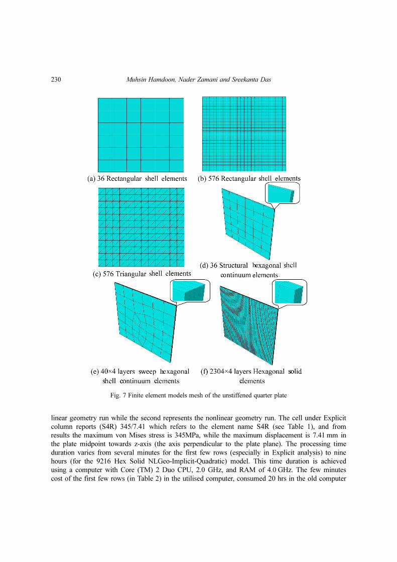
A variety of finite element models were tested taking into account element class, formulation,
mesh, non linearity and other effective parameters as shown in Fig. 7. The numerical test matrix is
shown in Table 2. Each row represents a finite element model with up to five software runs
including Explicit and Implicit time integration schemes (with linear and quadratic analysis), as well
as linear and non linear geometry consideration. Each cell indicates element name followed by
maximum von Mises stress recorded and maximum displacement, respectively over the entire time
domain. The measurements are targeting the midpoint of the plate (point D in Fig. 6). For example,
the first row illustrates the 36 rectangular shell elements model with two lines: the first represents
Fig. 6 Geometry and boundary conditions of the unstiffened square plate
230 Muhsin Hamdoon, Nader Zamani and Sreekanta Das
linear geometry run while the second represents the nonlinear geometry run. The cell under Explicit
column reports (S4R) 345/7.41 which refers to the element name S4R (see Table 1), and from
results the maximum von Mises stress is 345MPa, while the maximum displacement is 7.41 mm in
the plate midpoint towards z-axis (the axis perpendicular to the plate plane). The processing time
duration varies from several minutes for the first few rows (especially in Explicit analysis) to nine
hours (for the 9216 Hex Solid NLGeo-Implicit-Quadratic) model. This time duration is achieved
using a computer with Core (TM) 2 Duo CPU, 2.0 GHz, and RAM of 4.0 GHz. The few minutes
cost of the first few rows (in Table 2) in the utilised computer, consumed 20 hrs in the old computer
Fig. 7 Finite element models mesh of the unstiffened quarter plate

FEA of the blast loading effect on ships hull 231
processor (FPS364) using time step of 5 × 10⁻² second for just 10 msec of processing4. The current
relatively high processing speed enabled for extensive runs to study effects of the different
variables.
3.3.2 FE models of the stiffened panel
The stiffened panel (which consists of plate and stiffeners, Fig. 4 is modeled in the FE software in
two manners: first as one part and second as two parts as shown in Fig. 8. For the one part model
the numbers of triangular shell elements are 192 and 672 for plate and stiffener, respectively.
However, the two part model meshed with two different meshes for the plate using 336 and 1728
elements in two sub models, while the stiffener maintained at 672 elements for both models. The
offset between plate and stiffener has a significant effect on the numerical results, so it was took
into account and estimated as the summation of half thickness of each part.
Table 2 Unstiffened plate test matrix
Number of/ Element Name ExplicitImplicit
Linear Quadratic
36 Rec Shell Lin Geo* (S4R) 345/7.41** (S4R) 345/11.15 (S8R) 345/10.54
NLGeo (S4R) 345/7.18 (S8R) 345/7.32
144 Rec Shell Lin Geo (S4R) 345/10.63 (S8R) 345/10.50
NLGeo (S4R) 345/7.43 (S4R) 345/7.33 (S8R) 347/7.35
576 Tri Shell Lin Geo (S3) 345/10.69 (STRI65) 345/10.51
NLGeo (S3R) 344/7.29 (S3) 345/7.31 (STRI65) 347/7.38
2304 Tri Shell NLGeo (S3R) 344/7.37 (S3) 340/7.33
576 Rec Shell NLGeo S4R 345/7.37 (S4R) 339/7.35 (S8R) 345/7.35
36 × 4 Hex Str. Shell Cont (SC8R) 414/-1.15
NLGeo N/A (SC8R) 414/-1.15 N/A
40 × 4 Hex Shell Cont (SC8R) 249/7.15
NLGeo N/A (SC8R) 262/6.6 N/A
36 × 4 Hex Solid Lin Geo (C3D8R) 0.52/-0.02
36 × 4 Hex Solid NLGeo N/A (C3D8R) 3.4/-0.1 (C3D20R) 341/7.28
576 × 4 Hex Solid LinGeo (C3D8R) 35/-3.21 (C3D8R) 191/5.91
576 × 4 Hex Solid NLGeo N/A (C3D8R) 208/5.21 (C3D20R) 306/7.36
2304 × 4 Hex Solid LinGe (C3D8R) 242/6.31 (C3D8R) 283/10.1
2304 × 4 Hex Solid NLGeo N/A (C3D8R) 345/7.30 (C3D20R) 347/7.36
9216 × 4 Hex Solid LinGe (C3D8R) 323/7.38
9216 × 4 Hex Solid NLGeo N/A (C3D8R) 343/7.33 (C3D20R)
*Lin Geo: Linear Geometry, and NLGeo: Non Linear Geometry.**The values in cells indicate element name, stress and displacement for certain run. For example: (S4R) 345/7.41 means the element name is S4R (see table 1), the maximum von Mises stress is 345 MPa and themaximum displacement is 7.41 mm.

232 Muhsin Hamdoon, Nader Zamani and Sreekanta Das
4. Results and discussion of the fea results
4.1 Results and discussion of unstiffened plate
4.1.1 Shell elements
The numerical results found from FE software in terms of displacement-time relationship indicate
a satisfactory agreement with experimental results. Fig. 9 illustrates same trend in both of the
Explicit and Implicit time integration schemes comparing with experimental sinusoidal wave, for
most of the shell elements models. When the non-linear geometry property in the software is
“checked”, the numerical curves became underestimated till time of 3.5 msec. For time period of
(3.5 to 5.0 msec) the behaviour became coincidence in displacement value with time delay shift of
0.5msec. Finally it exhibit underestimation for the rest of time domain. When the non-linear
geometry property “unchecked” (linear geometry case) such as the model (576 triangular shell linear
Implicit-linear geometry) the plate response changed. There is underestimate till time of 2 msec,
then it exhibited overestimate for the time period of (2.0 to 4.5 msec), followed by underestimation
from (4.5 to 6.0 msec) and finally overestimation for the rest of time domain. This trend diversity
between the last model and other models is due to turning off/on the non-linear geometry property.
This property allows considering high deflection in calculations, in case of turning on. It can be
concluded that the behaviours of most shell elements models are soft in both elastic and plastic
ranges in case of non-linear geometry, while the behaviour of the linear geometry model consists of
a combination of soft and stiff modes, with stiffness dominancy. For the last observation, there is
Fig. 8 Finite element models mesh of quarter bay in the stiffened panel

FEA of the blast loading effect on ships hull 233
neither difference between Explicit and Implicit schemes results, nor the two methods of Implicit
(linear and quadratic).
No effect observed of shell elements mesh refinement on the results, for example the 36 elements
model produces the same results of the 2304 elements model. Furthermore, the element shape
(rectangular or triangular) doesn’t affect the results. The current study results of displacement-time
relationship of the shell elements models (with non-linear geometry) agree with Houlston and Slater
results of FE analysis which carried out using Newmark time integration method (Houlston and
Slater 1987).
4.1.2 Shell continuum elements
Fig. 10 shows the displacement-time relationship of the shell continuum elements models, one
shell elements model, in addition to the experimental results. The 36 shell continuum elements
model in Explicit scheme produced a coincidence results with the 576 conventional shell element
model. This observation has an advantage of shell continuum elements over shell elements
Fig. 9 Displacement-time relationship of the shell elements FE models compared with experimental resultsfor the unstiffened plate
Fig. 10 Displacement-time relationship of the shell continuum elements FE models compared with shell andexperimental results for the unstiffened plate

234 Muhsin Hamdoon, Nader Zamani and Sreekanta Das
concerning processing time cost, especially in case of fine mesh or complex geometry. However
there is a slight shift of shell continuum Implicit model comparing with Explicit one, led to more
divergence with respect to the experimental results. From another point of view, the number of layer
has no effect on results whereas the one layer produces the same results such as that of the four
layers. That’s an additional advantage for shell continuum elements over solid elements whereas the
first has five integration points through thickness enables to record response and excluding layers
duplication. The sweep meshing is more consistent with shell continuum elements while structured
one doesn’t work accurately with these elements.
4.1.3 Solid Elements
Fig. 11 illustrates the solid elements models, one of the shell elements models, in addition to the
experimental results. The most important observation here is the mesh refinement. The response of
the course mesh solid elements model (i.e., 36 elements) was very stiff response, so its dis-
placements are very small comparing with experimental results. The reason of this stiff behaviour is
the volumetric locking where the strain exceeds 20-40%, and to minimize the effect of this problem,
a finer mesh should be used. The least number of elements sufficient to achieve the task is 2304
elements (in case of Explicit scheme) and 576 elements (in case of quadratic Implicit scheme) with
four layers to capture stress and strain accurately. The behaviour of the non-linear geometry models
are the same such as that of the shell elements (mentioned above). Likewise, the linear geometry
linear Implicit model produced the same response (of alternation in under and overestimation) such
as that of the shell elements.
4.1.4 Equivalent plastic strain (PEEQ)
The equivalent plastic strain (PEEQ) in a material is a scalar variable that is used to represent the
material's inelastic deformation. If this variable is greater than zero, the material has yielded
(ABAQUS 6.8 User’s Manual 2008). Fig. 12 shows the regions where the maximum PEEQ occurs.
The clamped upper and right edges experienced higher values of the plastic strain whereas the
bending stress is also of maximum value.
4.1.5 Spatial distribution of displacement
Fig. 13 describes the spatial distribution of the midpoint displacement contour during selected
times for the unstiffened plate. In the early test time (0.4 msec), the maximum displacement occurs
in the plate midpoint, in the negative z-axis direction and looks like a rectangle, as shown in
Fig. 13(a). Later the maximum displacement contour starts forming a circular shape. The
Fig. 11 Displacement-time relationship of the solid elements FE models compared with shell and experi-mental results of the unstiffened plate

FEA of the blast loading effect on ships hull 235
Fig. 13 Displacement contour plots at selected times of 576 rectangular shell Explicit FE model of theunstiffened plate, the blue colour indicates the maximum negative displacement and red for themaximum positive displacement
Fig. 12 Equivalent plastic strain distribution over the unstiffened plate of the 576 rectangular shell ExplicitFE model

236 Muhsin Hamdoon, Nader Zamani and Sreekanta Das
displacement contra flexure point was recorded at time of 3.6 msec where the displacement converts
its sign to positive, at this time the midpoint recorded positive displacement of + 0.42 mm while the
middle area of the quarter plate recorded maximum displacement of + 1.25 mm Fig. 13(e).
Subsequently, the displacement continues increasing in positive z-direction till time of 5.0 msec,
then decreasing to reach its zero value at time of 6.7 msec, and convert its direction to negative for
the remaining time. There is a central area of minimum displacement of −1.02 mm occurred in the
middle of the quarter plate FE model at time of 6.4 ms Fig. 13(g). The spatial distribution of
displacement found through this study agrees with that presented by (Houlston and Slater 1985).
4.2 Results and discussion of stiffened panel
The comparisons between FE analysis and experimental results in terms of displacement-time
relationship of stiffened plate and beam stiffener are shown in Figs. 14 and 15, respectively. There
Fig. 14 Displacement-time relationship of the FE models compared with experimental results of the stiffenedplate, A2: Accelerometer, D12: LVDT Displacement gauge (both located at midpoint of plate bay,point A in Figs. 8(a) and (b))
Fig. 15 Displacement-time relationship of the FE models compared with experimental results of the stiffenerbeam, A3: Accelerometer, D13: LVDT Displacement gauge (both located at midspan of the beam,point D in Fig. 8(a))

FEA of the blast loading effect on ships hull 237
is a good agreement between numerical and experimental results for the plate especially for the
displacement gauge (D12) and the “one part” FE model, in its three runs: Explicit, linear Implicit
and quadratic Implicit. The “two parts” FE models (336-672 and 1728-672) is relatively
overestimates in negative displacement and fluctuate with high amplitude comparing with the two
experimental curves A2 and D12. The meshing refinement has no effect in these analyses and that
agrees with the unstiffened plate FE analysis for shell elements models. It can be concluded that the
one part FE model is the best model regardless the time integration scheme (Explicit or Implicit)
used in processing.
The same observation can be anticipated from stiffener beam experimental and numerical analysis.
It’s obviously shown the good agreement between A3 and D13 experimental results and the results
of the (192-672 one part) FE model results. There is a slight convergence between Explicit and
linear Implicit models with the experimental results, while the quadratic Implicit model diverges
slightly. However, the two parts models produced overestimated displacement with high amplitude
waves. The FE results of stiffened panel in terms of displacement-time relationship found from this
study agrees with that presented by Houlston and Slater (1987) and Kadid (2008).
Fig. 16 Shows displacement contour plots at selected times of the (192-672 triangular shell
Explicit one part) FE model of the stiffened panel. The maximum and minimum values are
indicated in its locations. The maximum positive value (zero) has a fixed location lies in the upper
right corner, while the minimum value (maximum negative value) changes its location alternatively
during time domain.
The equivalent plastic strain distribution over the stiffened panel of the (192-672 triangular shell
Explicit one part FE model) is illustrates in Fig. 17. The maximum PEEQ is located in the lower
Fig. 16 Displacement contour plots at selected times of 192-672 triangular shell Explicit one part FE modelof the stiffened panel, the blue colour indicates the maximum negative displacement and red formaximum positive displacement

238 Muhsin Hamdoon, Nader Zamani and Sreekanta Das
side of the clamped beam, and that’s expected where the maximum stresses expected to be in this
location. The maximum value of 0.04 is applied on the beam from time of (18 msec) to the end of
time domain (45 msec).
5. Conclusions
The numerical results found from the commercial FE software in terms of displacement-time
relationship produced a sufficient agreement with experimental results. The non-linear geometry
property has a significant effect on the FE models results. When it’s unchecked, it produces an
alternation of under and overestimation for the FE results comparing with experimental results. No
effect observed of shell elements mesh refinement on the results. Furthermore, the shell element
shape (rectangular or triangular) doesn’t affect the results.
A coarse mesh of shell continuum elements produces the same results of a fine mesh of shell
elements. This observation awards an advantage of shell continuum elements over the conventional
shell elements concerning processing time cost, especially in case of fine mesh or complex
geometry. Furthermore, one layer of the shell continuum elements is sufficient to achieve the blast
loaded plate analysis. This is an advantage for the shell continuum elements over solid elements
which need at least four layers to capture the plate response.
The response of the course mesh solid elements model has very stiff response, so its displacement
is very small comparing with experimental results. A very fine mesh is required for solid elements
model to produce acceptable results.
The “one part” FE model of the stiffened panel agrees with experimental displacement-time
relationship better than “two parts” FE models. The time integration scheme doesn’t affect FE
results in case of plate while its effect is very small regarding beam stiffener.
Fig. 17 Equivalent plastic strain distribution over the stiffened panel of the 192-672 triangular shell Explicitone part FE model

FEA of the blast loading effect on ships hull 239
Acknowledgements
We would like to acknowledge the National Science and Engineering Research Council of Canada
(NSERC) for their financial assistance submitted to achieve this work.
References
ABAQUS 6.8 User’s Manual (2008), Dassault Systèmes Simulia Corp., Providence, RI, USA.Cichocki, K. And Ruchwa, M. (2000), “Steel stiffened plates subjected to a blast load”, J. Phys. IV, 10(9), 535-
540.Houlston, R. and DesRochers, C.G. (1987), “Nonlinear structural response of ship panels subjected to air blast
loading”, Comput. Struct., 26(1-2), 1-15.Houlston, R. and Slater, J.E. (1985a), “On analysis of structural response of ship panels subjected to air blast
loading”, Comput. Struct., 21(1-2), 273-289.Houlston, R. and Slater, J.E. (1985b), “Structural response of panels subjected to shock loading”, US Naval
Research Lab, Shock & Vibration Information Cent, 55th Symposium on Shock and Vibration, Shock Vib.Bull.,149-163.
Houlston, R. and Slater, J.E. (1991), “Global and local modelling of naval panels subjected to shock loads”,Comput. Struct., 40(2), 353-364.
Houlston, R. and Slater, J.E. (1993), “Damage analysis with ADINA of naval panels subjected to a confined air-blast wave”, Comput. Struct., 47(4-5), 629-639.
Kadid A. (2008), “Stiffened plates subjected to uniform blast loading”, J. Civil Eng. Manage., 14(3), 155–161.Turkmen, H.S. and Mecitoglu, Z. (1999), “Dynamic response of a stiffened laminated composite plate subjected
to blast load”, J. Sound Vib., 221(3), 371-389.