feasibility analysis on a steam rankine cycle to recover
TRANSCRIPT
ISSN: 1791-4469 Copyright © 2012 Hellenic Naval Academy
35
Feasibility Analysis on a Steam Rankine Cycle to Recover Heat from a Gas Turbine used on a Naval
Vessel
Efthimios G. Pariotis*, Ioannis Katsanis and Ioannis Roumeliotis
Laboratory of Naval Propulsion Systems, Section of Naval Architecture and Marine Engineering, Department of Naval Sciences, Hellenic Naval Academy, End of Hatzikiriakou Ave., 18539
Piraeus, Greece [email protected], Tel.: +30 210 4581663; Fax: +30 211 7701574.
Abstract. The design concept of some special purpose naval vessels requires the usage of gas turbines as prime mover engines, which offer high power density and high flexibility on the variation of the engine load. However, one of the disadvantages of the gas turbines compared to their main competitors, the diesel engines, is their lower fuel efficiency. The comparison becomes ever worse when referring to the part load engine conditions, especially for the legacy gas turbines installed in some vessels of the Hellenic Navy. The part load operation is of paramount importance for the case of marine propulsion, since the engines operate most of the time at part load. Apart from the economic impact of the relatively high fuel consumption of the installed gas turbines, there are also operational issues that arise and have to be considered. The engine�s fuel consumption affects the planning of the required fuel supply chain and the operational range of the vessel. In the present study, a preliminary feasibility analysis of installing a waste heat recovery bottoming Rankine cycle with steam as a working medium is conducted, in order to estimate the improvement of the fuel consumption over the entire operating range for a gas turbine used as a base prime mover at the Hellenic Navy. For this purpose, a gas turbine performance model is used to calculate the flue gas properties (temperature and mass flow rate) during the engine off-design operation and is coupled with a thermodynamic model that simulates the Rankine cycle and predicts the thermodynamic properties of water/steam at all operating conditions. The analysis takes into account constraints regarding the available space for installing the various components and especially the exhaust gas heat exchanger (HRSG), as well as the lower limit of the exhaust gas temperature to avoid condensation. From this preliminary investigation it has been confirmed that with the proposed configuration, a significant improvement on the overall (combined) efficiency can be obtained ranging from 33% at full power to 53% at 25% of the gas turbine load, providing a technically feasible solution to the problem of low gas turbine engine efficiency, especially at part load operation. Moreover, at the same time, this technique provides tactical benefits, since it lowers the exhaust gas temperature which consequently affects the infrared �signature� of the ship, making its tracking by the enemy harder.
Keywords: Gas Turbines, Waste heat recovery, Steam Rankine cycle, COGAS.

NAUSIVIOS CHORA
36
INTRODUCTION
The classical heat engine cycles for power generation in steam and gas turbine plants are those associated with the names of Rankine and Joule-Brayton [1]. The temperature-entropy diagrams for these cycles are shown in Figs. 1A and 1B respectively. The Rankine cycle is the basis of steam power plant, with steady flow through a boiler, a turbine driving a generator delivering electrical or mechanical power, a condenser and a feed-pump. The Joule-Brayton constant pressure cycle is the basis of the gas turbine power plant, with steady flow of air (or gas) through a compressor, the heater, the turbine, and the cooler within a closed circuit. The turbine drives both the compressor and the generator delivering electrical power or provides mechanical power on a power shaft.
FIGURE 2A. Rankine cyclic heat engine [1] FIGURE 1B. Joule � Brayton cyclic heat
engine [1]
One particularly important field of study for conventional power plant design is that of the ''combined plant''. A broad definition of the conventional ''combined cycles'' is the cycles that are coupled to work together, in such a way that the heat rejected from the one power cycle (as dictated by the 2nd Law of thermodynamics) which is called upper or topping cycle, becomes the heat source for the other which is called lower or bottoming cycle, in order to produce more useful power. In practice the ''upper'' plant is often open circuit, not cyclic. In this way it becomes feasible to produce greater work output for a given heat (or fuel energy) supply, i.e. improved energy efficiency. Using the second Law of Thermodynamics it is proved that the maximum efficiency of a heat engine is achieved when it is operated according to the reversible Carnot cycle between a given (maximum) constant temperature (TB) of heat supply (QB) and a given (minimum) temperature (TA) of heat rejection (QA) (according to the temperature �entropy diagram shown in Fig. 2). Its thermal efficiency is given by the following expression:
(1)
ISSN: 1791-4469 Copyright © 2012 Hellenic Naval Academy
37
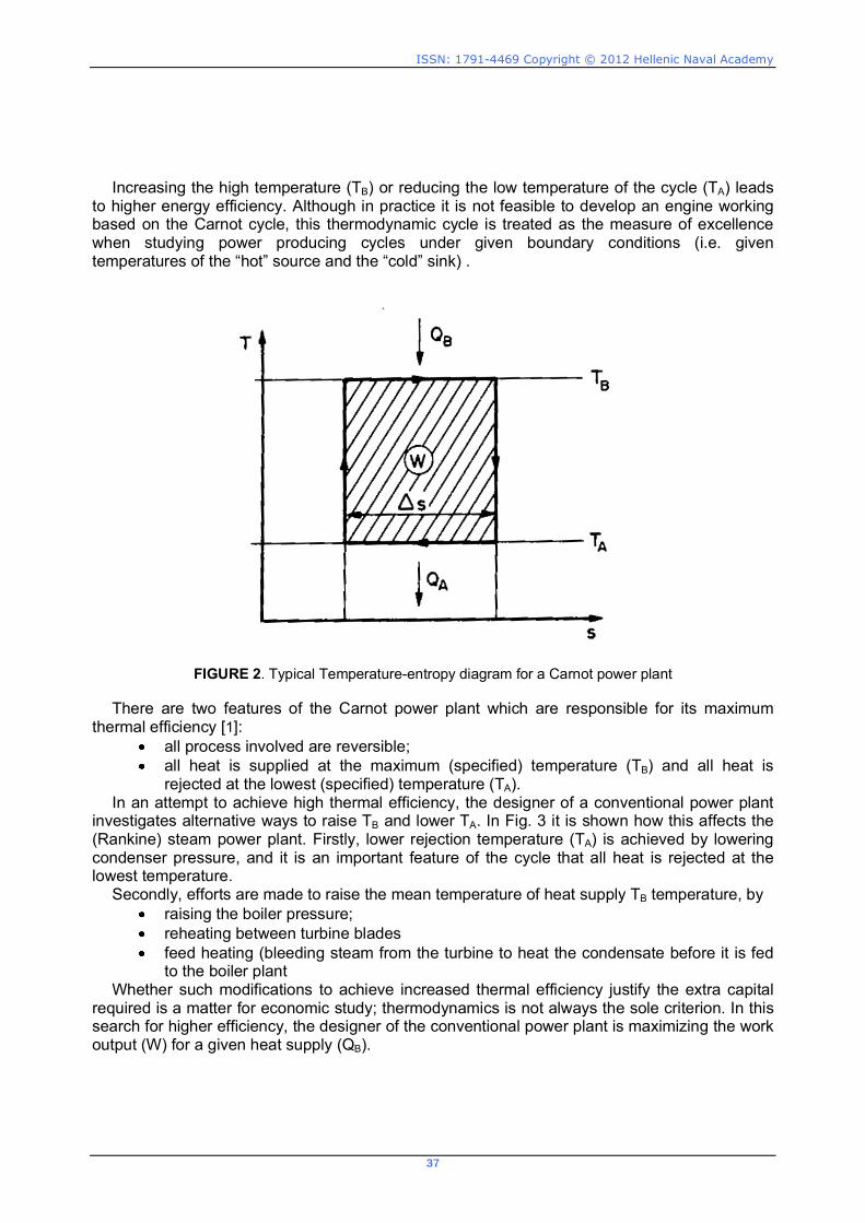
Increasing the high temperature (TB) or reducing the low temperature of the cycle (TA) leads to higher energy efficiency. Although in practice it is not feasible to develop an engine working based on the Carnot cycle, this thermodynamic cycle is treated as the measure of excellence when studying power producing cycles under given boundary conditions (i.e. given temperatures of the �hot� source and the �cold� sink) .
FIGURE 2. Typical Temperature-entropy diagram for a Carnot power plant There are two features of the Carnot power plant which are responsible for its maximum
thermal efficiency [1]: all process involved are reversible; all heat is supplied at the maximum (specified) temperature (TB) and all heat is
rejected at the lowest (specified) temperature (TA). In an attempt to achieve high thermal efficiency, the designer of a conventional power plant
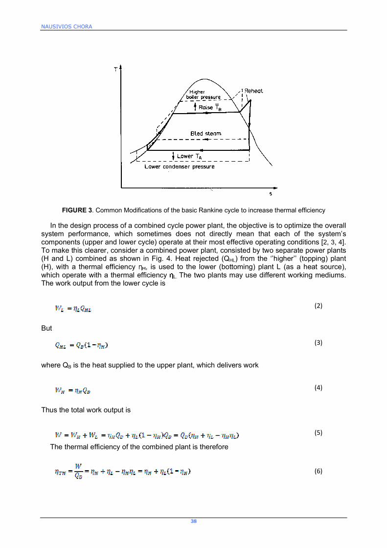
investigates alternative ways to raise TB and lower TA. In Fig. 3 it is shown how this affects the (Rankine) steam power plant. Firstly, lower rejection temperature (TA) is achieved by lowering condenser pressure, and it is an important feature of the cycle that all heat is rejected at the lowest temperature.
Secondly, efforts are made to raise the mean temperature of heat supply TB temperature, by raising the boiler pressure; reheating between turbine blades feed heating (bleeding steam from the turbine to heat the condensate before it is fed
to the boiler plant Whether such modifications to achieve increased thermal efficiency justify the extra capital
required is a matter for economic study; thermodynamics is not always the sole criterion. In this search for higher efficiency, the designer of the conventional power plant is maximizing the work output (W) for a given heat supply (QB).
NAUSIVIOS CHORA
38
FIGURE 3. Common Modifications of the basic Rankine cycle to increase thermal efficiency In the design process of a combined cycle power plant, the objective is to optimize the overall
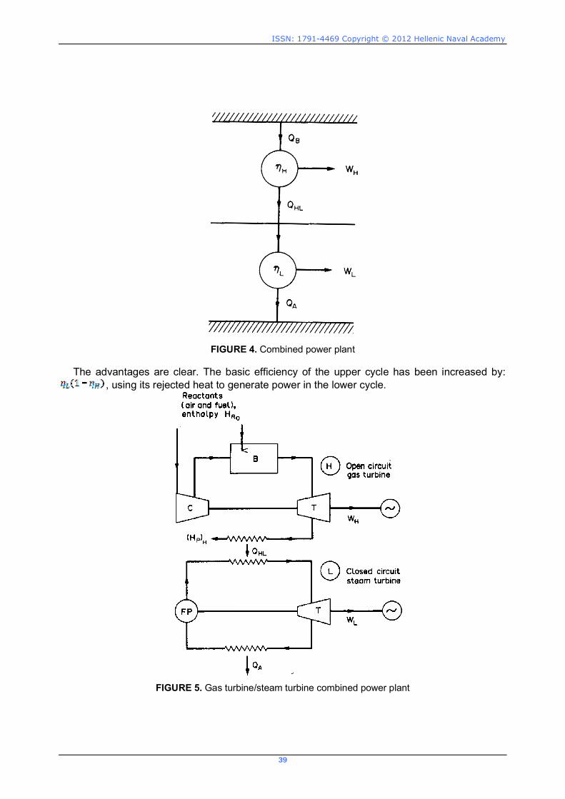
system performance, which sometimes does not directly mean that each of the system�s components (upper and lower cycle) operate at their most effective operating conditions [2, 3, 4]. To make this clearer, consider a combined power plant, consisted by two separate power plants (H and L) combined as shown in Fig. 4. Heat rejected (QHL) from the ��higher�� (topping) plant (H), with a thermal efficiency , is used to the lower (bottoming) plant L (as a heat source), which operate with a thermal efficiency L. The two plants may use different working mediums. The work output from the lower cycle is
(2)
But
(3)
where QB is the heat supplied to the upper plant, which delivers work
(4)
Thus the total work output is
(5)
The thermal efficiency of the combined plant is therefore
(6)
ISSN: 1791-4469 Copyright © 2012 Hellenic Naval Academy
39
FIGURE 4. Combined power plant
The advantages are clear. The basic efficiency of the upper cycle has been increased by:
, using its rejected heat to generate power in the lower cycle.
FIGURE 5. Gas turbine/steam turbine combined power plant

NAUSIVIOS CHORA
40
When the upper cycle is consisted by a gas turbine, one of the most familiar ways to further exploit the energy of the exhaust gases is to combine the upper cycle with a bottom Rankine cycle equipped with a steam turbine. A typical configuration is the one shown in figure 5. The combination of an open cycle gas turbine with a water/steam cycle, commonly known as the combined cycle, offers several advantages [4, 5]:
Air/Exhaust gas is a straightforward medium that can be used in modern gas turbines at high turbine inlet temperature levels (above 1200°C), providing the optimum prerequisites for a good topping cycle.
Steam/water is inexpensive, widely available, non-hazardous, and suitable for medium and low temperature ranges, being ideal for the bottoming cycle.
In this case the combined efficiency of the plant can be expressed by the following equation:
(7)
Differentiation makes it possible to estimate how the overall combined plant efficiency is
affected by a change in the efficiency of the gas turbine:
(8)
Thus, increasing the gas turbine efficiency improves the overall efficiency only if:
(9)
which leads to:
(10)
The last equation shows that improving the gas turbine efficiency is helpful only if it does not
cause a high drop in the efficiency of the bottoming cycle (nST). Table 1 indicates that when the efficiency of the gas turbine is raised, there is a limit on the allowable decrease of the bottom rankine cycle efficiency, in order this to have a positive effect on the overall combined cycle efficiency. For example, steam process efficiency can be reduced from 30% to 27.8% (
in case the gas turbine efficiency is raised from 30% to 35% to keep the overall combined-cycle efficiency.
TABLE 1. Example of the allowable reduction in the bottoming cycle efficiency nST when the gas turbine efficiency
nGT increases from 30% to 35% or 40%, in order to keep the overall combined-cycle efficiency. 0.3 0.35 0.4
1.0 1.08 1.17
ISSN: 1791-4469 Copyright © 2012 Hellenic Naval Academy
41
IMPLEMENTATION OF A COMBINED CYCLE FOR MARINE APPLICATIONS
The recent changes in the emission legislation with the burdens on the maximum content of sulfur in the marine fuels, as well as, the inherent advantages of the gas turbines as prime movers, together with the development of advanced systems with high overall efficiency, have grown the interest regarding the usage of gas turbines as prime movers for vessels instead of using diesel engines [4, 6, 7, 8, 9]. Especially for the navy, gas turbines offer high flexibility on the operating conditions, low demand in maintenance and high power density, which make them ideal for specific types of vessels (i.e. combatants) [10]. However, the operational demands and the growing fuel prices have raised skepticism regarding the relatively low overall engine efficiency of the gas turbines used in the Hellenic Navy, as well as in the foreign Navies worldwide. One of the solutions proposed is the modification of the existing gas turbine power plants, by adding a bottoming cycle (Rankine) working with steam/water in order to recover a portion of the heat rejected to the environment with the exhaust gases. This excess power could be offered to cover a portion of the electric loads of the ship (reducing the fuel consumption of the auxiliary engines), or could be provided as propulsion power through an appropriate gear box. The US Navy has studied such alternatives since the 80s and the conclusions derived are positives [10].
In the present work a preliminary investigation is conducted in order to explore the feasibility of adding a bottom cycle (i.e. Rankine with steam as the working medium) to the existing gas turbine configuration which is used as the basic propulsive power unit on a combatant vessel of the Hellenic Navy. In this first part of our research work, the investigation is limited to the determination of the possible power increment and the corresponding improvement of the overall system efficiency taking into account specific limitations which exist, regarding the allowable lower exhaust gas temperature and the dimensions of the heat exchanger used for the exhaust gas heat recovery (Heat Recovery Steam Generator, i.e. HRSG).
Gas Turbine Model
In order to model the off � design operation of the gas turbine a generic, zero-dimensional non-linear adaptive performance model is used [12]. The model is based on the logic that a gas turbine is an assembly of different components (modules). Each component is identified and modelled according to the kind of aero-thermodynamic process it materializes. For each component, if YIN is the vector of the independent variables at its inlet and YOUT the corresponding vector at its outlet, then in order to find the values at the component exit an equation of the following form must be solved.
IN OUTg(Y ,Y ) 0 (11)
This equation usually derives from conservation laws, as well as from existing experience in
components operation. It may consist of analytical relations, possibly including empirical constants (e.g. duct pressure loss), or a set of curves (e.g. turbo-machinery component maps). Additional equations express the compatibility of operation between the different components, imposing �matching� conditions, as for example, power balance between the high pressure turbine and compressor. In this way a set of equations, which have to be simultaneously satisfied by the fluid parameters, is formed. The solution of this system of equations, non-linear in nature, is achieved numerically. Different types of numerical techniques can be employed, as
NAUSIVIOS CHORA
42
for example described by Stamatis et al. [13]. The solution of this system of equations, for an operating point as specified by the ambient conditions and the selected engine control variable (e.g. engine load, Turbine Entry Temperature etc.), gives the full cycle details, and the performance parameters are uniquely defined for off-design operation.
The model is capable of simulating all existing gas turbine configurations from single shaft engines, up to a three spool engines with power turbine with intercooling, reheating, recuperation and water injection at various positions along the engine. The model layout and the system of equations to be solved are modified in accordance with the engine configuration under consideration. Also, as the control variable of different engines may be different, or even change throughout their operation, the model is capable to acknowledge several parameters as control variables like Turbine Entry Temperature (TET), Compressor Discharge Pressure (CDP), load etc. depending on the engine configuration.
In order to be capable to simulate a specific engine the model can be adapted to available, engine specific data by employing the adaptive modelling technique, introduced by Stamatis et al. [14]. The basic idea behind adaptive modelling is that component characteristics (e.g compressor map) are allowed to change through appropriate modification factors. The values of these factors are determined by requiring that available engine performance data are matched by the engine model. In this way, at the end of the adaptation procedure, a set of components characteristics is produced which are capable to reproduce the specified engine operation with great accuracy (e.g Tsalavoutas et al. [15]).
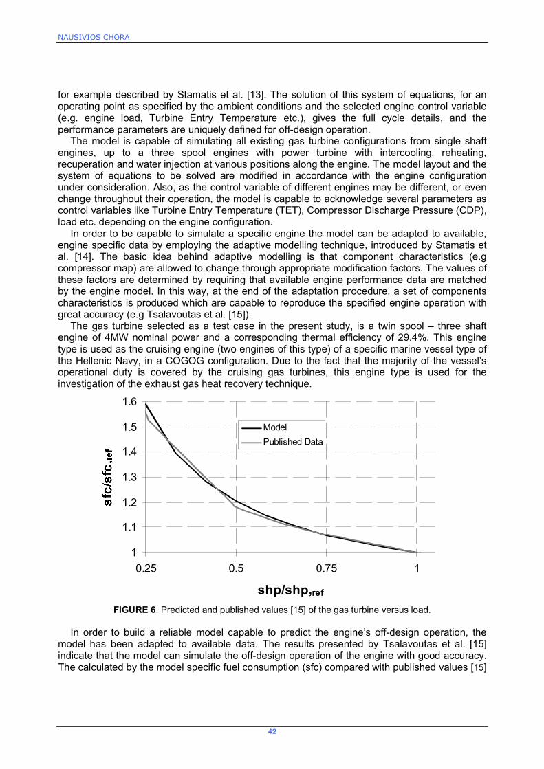
The gas turbine selected as a test case in the present study, is a twin spool � three shaft engine of 4MW nominal power and a corresponding thermal efficiency of 29.4%. This engine type is used as the cruising engine (two engines of this type) of a specific marine vessel type of the Hellenic Navy, in a COGOG configuration. Due to the fact that the majority of the vessel�s operational duty is covered by the cruising gas turbines, this engine type is used for the investigation of the exhaust gas heat recovery technique.
1
1.1
1.2
1.3
1.4
1.5
1.6
0.25 0.5 0.75 1
shp/shp,ref
ModelPublished Data
FIGURE 6. Predicted and published values [15] of the gas turbine versus load.
In order to build a reliable model capable to predict the engine�s off-design operation, the
model has been adapted to available data. The results presented by Tsalavoutas et al. [15] indicate that the model can simulate the off-design operation of the engine with good accuracy. The calculated by the model specific fuel consumption (sfc) compared with published values [15]
ISSN: 1791-4469 Copyright © 2012 Hellenic Naval Academy
43
versus the operating load is presented in Figure 6. The adapted model is used for calculating the exhaust flow properties (mass flow, temperature and composition) at specific operating points.
Heat Recovery Steam Generator Design
One of the most important parts of the Rankine cycle is the heat recovery steam generator (HRSG) since it is the component of the cycle which is responsible for the exhaust heat recovery (and the production of steam, with adequate thermodynamic properties). This component of the bottoming cycle contributes considerably to the system�s weight and volume. These two parameters are crucial for marine applications in general and even more crucial when the application concerns a naval vessel. In general there are two types of Heat recovery steam generators (HRSG): The once-through type and the drum-type.
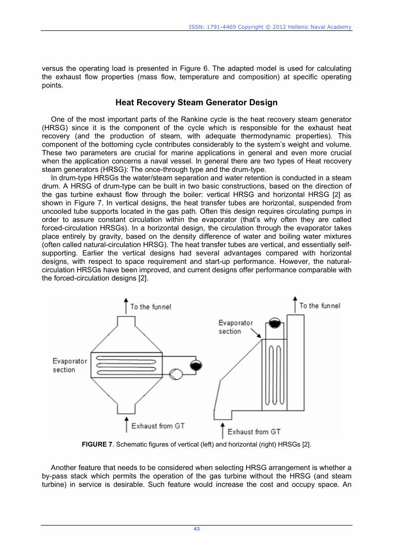
In drum-type HRSGs the water/steam separation and water retention is conducted in a steam drum. A HRSG of drum-type can be built in two basic constructions, based on the direction of the gas turbine exhaust ow through the boiler: vertical HRSG and horizontal HRSG [2] as shown in Figure 7. In vertical designs, the heat transfer tubes are horizontal, suspended from uncooled tube supports located in the gas path. Often this design requires circulating pumps in order to assure constant circulation within the evaporator (that�s why often they are called forced-circulation HRSGs). In a horizontal design, the circulation through the evaporator takes place entirely by gravity, based on the density difference of water and boiling water mixtures (often called natural-circulation HRSG). The heat transfer tubes are vertical, and essentially self-supporting. Earlier the vertical designs had several advantages compared with horizontal designs, with respect to space requirement and start-up performance. However, the natural-circulation HRSGs have been improved, and current designs offer performance comparable with the forced-circulation designs [2].
FIGURE 7. Schematic figures of vertical (left) and horizontal (right) HRSGs [2].
Another feature that needs to be considered when selecting HRSG arrangement is whether a
by-pass stack which permits the operation of the gas turbine without the HRSG (and steam turbine) in service is desirable. Such feature would increase the cost and occupy space. An

NAUSIVIOS CHORA
44
important drawback with the drum-type HRSG is that for high live-steam pressures the operational exibility is restricted. Combined cycles used for marine applications are often operated in cycling duties with frequent load changes and start-up cycles. Such operation causes high thermal stresses on parts within the HRSG, especially on the drum. Thus, the loading rate, for example during start-up, is primarily constrained by the drum.
On the other hand a once-through HRSG is basically one tube, featuring the economizer, the evaporator and the super-heater. Water enters at one end and steam leaves at the other, eliminating the drum and circulation pumps. Since it contains no drum, it provides the desired high thermal exibility. However, as all the water mass ow should evaporate when owing through the HRSG, the area requirement of the evaporator section is large. In a HRSG of drum-type, the water is re-circulated and only a portion of the ow is evaporated at the time, thereby requiring less heat transferring area.
Previous work on the use of combined cycles for marine applications does not provide a coherent picture on the optimum choice of the HRSG type. Taking into account the space limitations which apply on a naval vessel, in this study a once-through heat exchanger is considered with vertical gas ow mounted directly over the gas turbine, as shown in figure 8. Such a design would minimize ground-oor and space requirements. Additionally, a vertical arrangement is associated with a low cost and it provides a good exhaust gas distribution across the boiler heating surfaces. On the other hand, this configuration may set some obstacles to the maintenance of the gas turbine, but taking into account the very limited available space this configuration seems to be the optimum solution.
In this HRSG, the feed water is introduced at the gas outlet and is moved through the core until it leaves the other end at the desired condition (superheated). The steam exit conditions are controlled by the feed-water flow rate. A low water flow rate produces high superheat, high minimum wall temperatures of the heat exchanger tubes and low heat recovery. This control feature is utilized in this study since focus has been given to maintain a minimum exhaust gas temperature at the exit of the boiler (economizer) above the sulfur-acid dew point. Specifically, this limit value was assumed equal to 135°C, which is slightly above the dew point of the specific gas turbine exhaust gas. It is noticed that in the Greek Navy the standard fuel used in the gas-turbine-powered combatants has a maximum sulfur content equal to 1% [16].
HRSG Design
To simplify the simulation procedure, the dimensions of the HRSG are calculated based on relevant studies which have already been conducted by the US Navy. Specifically the case study examined in [10] has been taken as a reference for the present work, where the bottom steam Rankine cycle has been applied on a LM2500 gas turbine which is used for propulsion of a combatant ship. Therefore the main design parameters of the HRSG used in the present study have been determined by appropriately scaling the corresponding data of this reference work. The HRSG has tubes with a nominal 3/4 inch diameter and nine fins per inch. These tubes are arranged in a staggered tube bank, while, no feed-water heating is considered, which means that the condenser water is fed directly to the economizer inlet. As far as the HRSG�s dimensions, these are assumed to be proportional to the ones of the reference HRSG. Specifically, the height of the HRSG is set equal to 2.40m (which corresponds to the ship�s deck-height), while the cross sectional area is determined so that the mean exhaust gas velocity at full engine load (4 MW), is identical to the one used in the aforementioned reference study. In this way, similar flow conditions are expected to exist, which makes the assumption of similar exhaust gas pressure losses and overall heat transfer conditions to be trustworthy. In the reference study the design exhaust gas flow rate is equal to 45.4 kg/s (corresponding to a power of 8.95 MW), and the dimensions of the boiler are: Length=2.7m, Width=2.7, Height=2.40m, with a total heat transfer area equal to 1230 m2. Taking into account that at the present study, the

ISSN: 1791-4469 Copyright © 2012 Hellenic Naval Academy
45
gas turbine�s exhaust gas mass flow rate at full power is equal to 18.3 kg/h, it can be concluded that the corresponding dimensions of the assumed HRSG are: Length=1.71m, Width=1.71, Height=2.40m, with a total heat transfer area equal to 495,79 m2.
FIGURE 8. Schematic diagram of the once-through HRSG [10] To further simplify the simulation procedure, the overall heat transfer coefficient Umean from
the gas side to water / steam, is assumed to be constant at the whole HRSG length and equal to the mean value of the one which has been calculated in the reference study [10] since the flow conditions of the two streams of working mediums and especially the ones corresponding to the gas-side, which possesses the higher resistance to the heat transfer are similar with the ones which apply to the present study. Thus, the overall heat transfer coefficient Umean is assumed to be equal to 0.060 W/m2C [8, 10, 17].
Rankine Cycle Simulation Procedure
For this preliminary feasibility study a simple configuration of the combined power plant is examined, which comprises by: a Gas turbine power plant (following the Bryton cycle) and a simple Rankine cycle (bottom cycle), as shown in fig. 9.

NAUSIVIOS CHORA
46
FIGURE 9. Configuration of the Combined Cycle examined (Gas-Turbine / Water-Steam Rankine Cycle)
0 1 2 3 4 5 6 7 8 9 100
100
200
300
400
s [kJ/kg-K]
T [°
C]
300 kPa
200 kPa
100 kPa
10 kPa
400 kPa
0,2 0,4 0,6 x=0,8
T[i]T[i]
3
5
66is
4
12
FIGURE 10. Thermodynamic processes of the Rankine cycle examined
This bottoming cycle is composed by four main components: a pump, a heat exchanger
(HRSG), a steam turbine / generator and a condenser. As shown in fig. 10 the thermodynamic cycle for the steam/water working fluid considered, includes the following processes: a compression process in the pump (process 1-2), with an isentropic coefficient equal to nis,p=0.90, an isobaric heat transfer process in the heat exchanger (processes 2-3-4-5), an expansion process through the steam turbine with an isentropic coefficient nis,t=0.80 (process 5-6), and an isobaric heat transfer process in the condenser (process 6-1). The HRSG is assumed to be consisted by three parts: the economizer, the boiler and the super-heater (while these parts are considered to have �moving� boundaries depending on the operating conditions). The process (2-3) takes place in the economizer, the process (3-4) takes place in the boiler and the process (4-5) takes place in the super-heater. In the analysis conducted, it has been assumed
ISSN: 1791-4469 Copyright © 2012 Hellenic Naval Academy
47
that the steam quality at point 6is is equal to xlimit=0.82 [10], which ensures that problems associated with steam condensation at the late stages of the steam turbine are avoided.
The pump supplies the working uid to the heat exchanger, where the working uid is heated and vaporized removing heat from the exhaust gases. The working uid leaves the heat exchanger in saturated or superheated state (in order to fulfill the criterion which has been set for the steam quality after the expansion in the steam turbine). The high enthalpy steam is then expanded in the expander (turbine), which provides additional power to the vessel (electric or propulsion). After the expander, the working uid enters the condenser where it condensates (using another heat exchanger, utilizing the sea water as the medium to absorb the latent heat of water/steam condensation). Having this in mind, the condenser pressure has been set constant and equal to Pcond=10,1 kPa for all cases examined, so that a safe temperature difference between the working medium (water/steam) and the sea-water is ensured.
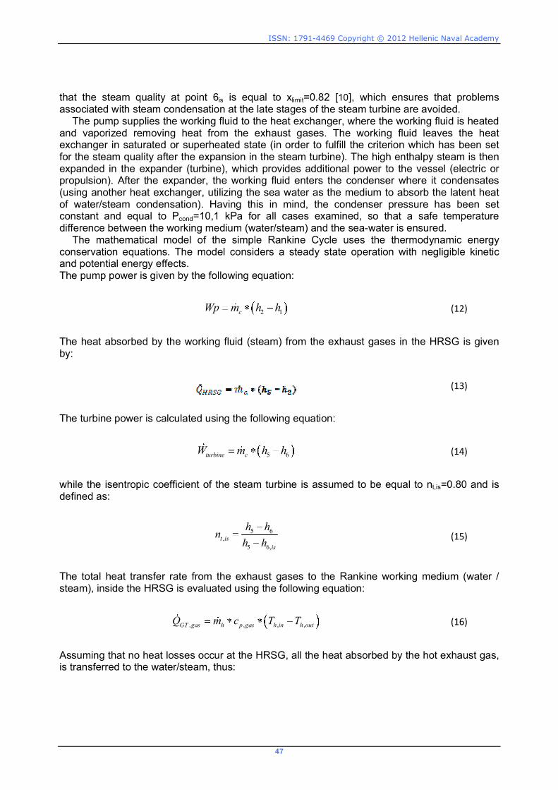
The mathematical model of the simple Rankine Cycle uses the thermodynamic energy conservation equations. The model considers a steady state operation with negligible kinetic and potential energy effects. The pump power is given by the following equation:
2 1cWp m h h (12)
The heat absorbed by the working fluid (steam) from the exhaust gases in the HRSG is given by:
(13)
The turbine power is calculated using the following equation:
5 6turbine cW m h h (14)
while the isentropic coefficient of the steam turbine is assumed to be equal to nt,is=0.80 and is defined as:
5 6,
5 6,t is
is
h hnh h (15)
The total heat transfer rate from the exhaust gases to the Rankine working medium (water / steam), inside the HRSG is evaluated using the following equation:
, , , ,GT gas h p gas h in h outQ m c T T (16)
Assuming that no heat losses occur at the HRSG, all the heat absorbed by the hot exhaust gas, is transferred to the water/steam, thus:
NAUSIVIOS CHORA
48
,HRSG GT gasQ Q (17)
Analogous expressions can be written for each part of the HRSG i.e. economizer, boiler and super-heater, through which the exhaust gas temperature at each part of the HRSG can be derived:
3 2 , ,3 ,ECON c h p gas h h outQ m h h m c T T (18)
4 3 , ,2 ,3BOILER c h p gas h hQ m h h m c T T (19)
5 4 , , ,2SUPERHTR c h p gas h in hQ m h h m c T T (20)
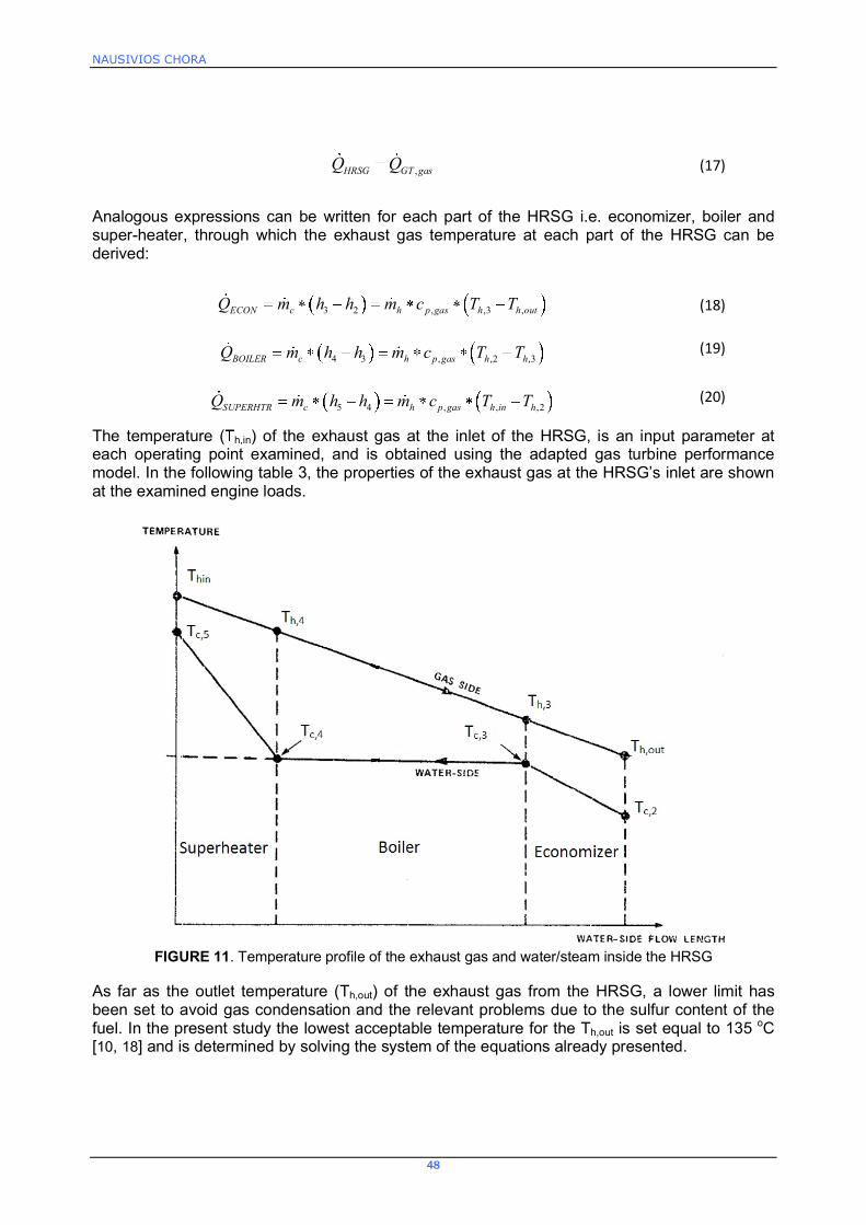
The temperature ( h,in) of the exhaust gas at the inlet of the HRSG, is an input parameter at each operating point examined, and is obtained using the adapted gas turbine performance model. In the following table 3, the properties of the exhaust gas at the HRSG�s inlet are shown at the examined engine loads.
FIGURE 11. Temperature profile of the exhaust gas and water/steam inside the HRSG
As far as the outlet temperature (Th,out) of the exhaust gas from the HRSG, a lower limit has been set to avoid gas condensation and the relevant problems due to the sulfur content of the fuel. In the present study the lowest acceptable temperature for the Th,out is set equal to 135 oC [10, 18] and is determined by solving the system of the equations already presented.

ISSN: 1791-4469 Copyright © 2012 Hellenic Naval Academy
49
Finally, a minimum temperature difference has been assumed between the inlet gas
temperature and the outlet steam temperature, which is equal to (Thin-Tc,5) 20 oC [9], for all the
operating conditions examined. Therefore the temperatures of the exhaust gas and water/steam at each part of the HRSG are predicted and the temperature profile of both streams is shown in fig.11. The last criterion used in the present study in order to solve the system of the aforementioned equations is related to the mass flow rate which passes through the steam turbine. It is known from the gas dynamics that a steam turbine behaves in a manner similar to a nozzle, which means that for a pressure ratio across the nozzle greater than approximately two (which is the case in the present study), the mass flow rate maximizes, the turbine is assumed
chocked and the corrected mass flow 0
0
cm TP
takes a constant value, as shown in Fig.12 [19].
More specifically the turbine�s mass flow rate is also influenced by the wheel-speed Mach number which is presented by:
0
NT
, thus a similar flow rate / pressure ratio relationship is
experienced as shown in fig. 13, where, 0
ref
TT and 0
ref
PP . Since the effect of the
corrected rotational speed is relatively small and there are no extractions it can be assumed that the steam turbine operates at a specific corrected mass flow for the whole operation envelope.
TABLE 3. Exhaust gas properties at the inlet of the HRSG
Gas Turbine Power (kW) Exhaust gas mass flow rate (kg/s)
Exhaust gas Temperature
(oC)
Gas Turbine Efficiency (%)
1000,00 12,00 346,90 18,50 1333,33 13,06 360,80 21,08 1666,67 14,03 374,40 22,97 2000,00 14,80 390,00 24,40 2333,33 15,57 405,40 25,60 2666,67 16,24 419,70 26,63 3000,00 16,80 435,60 27,50 3333,33 17,33 451,10 28,17 3666,67 17,87 465,70 28,84 4000,00 18,30 479,80 29,40
FIGURE 12. Variation of the mass flow rate through a nozzle as a function of the pressure ratio [19]
NAUSIVIOS CHORA
50
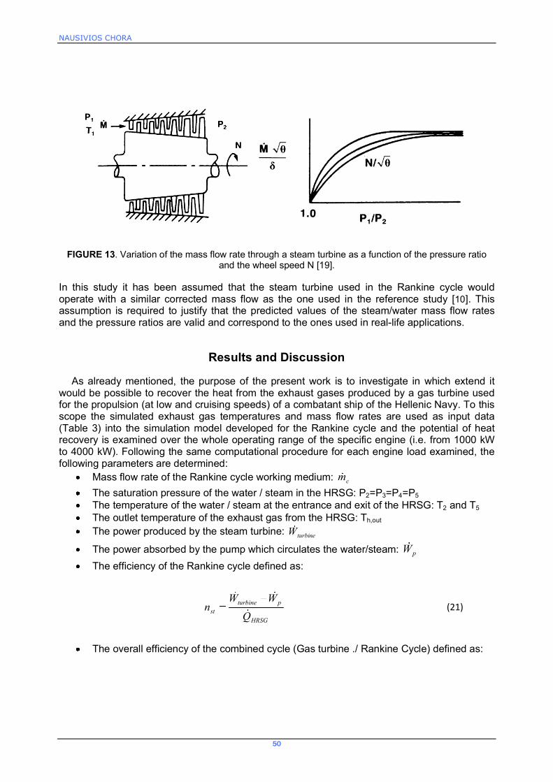
FIGURE 13. Variation of the mass flow rate through a steam turbine as a function of the pressure ratio and the wheel speed N [19].
In this study it has been assumed that the steam turbine used in the Rankine cycle would operate with a similar corrected mass flow as the one used in the reference study [10]. This assumption is required to justify that the predicted values of the steam/water mass flow rates and the pressure ratios are valid and correspond to the ones used in real-life applications.
Results and Discussion
As already mentioned, the purpose of the present work is to investigate in which extend it would be possible to recover the heat from the exhaust gases produced by a gas turbine used for the propulsion (at low and cruising speeds) of a combatant ship of the Hellenic Navy. To this scope the simulated exhaust gas temperatures and mass flow rates are used as input data (Table 3) into the simulation model developed for the Rankine cycle and the potential of heat recovery is examined over the whole operating range of the specific engine (i.e. from 1000 kW to 4000 kW). Following the same computational procedure for each engine load examined, the following parameters are determined:
Mass flow rate of the Rankine cycle working medium: cm The saturation pressure of the water / steam in the HRSG: P2=P3=P4=P5 The temperature of the water / steam at the entrance and exit of the HRSG: T2 and T5 The outlet temperature of the exhaust gas from the HRSG: Th,out The power produced by the steam turbine: turbineW
The power absorbed by the pump which circulates the water/steam: pW The efficiency of the Rankine cycle defined as:
HRSG
pturbinest Q
WWn (21)
The overall efficiency of the combined cycle (Gas turbine ./ Rankine Cycle) defined as:
ISSN: 1791-4469 Copyright © 2012 Hellenic Naval Academy
51
GT
GT
GTpturbinerealCC
nP
PWWn , (22)
where GTP is the power produced by the gas turbine and GTn is the gas turbine efficiency, both given as input to the model developed. It should be noticed that the combined efficiency nCC,real calculated from the equation above differs from the theoretical one nCC as defined in equation (7). This is attributed to the fact that in the definition of the ncc (theoretical efficiency) it has been assumed that all the heat rejected by the gas turbine, is absorbed by the bottoming cycle, which is not the case in real life applications due to the space limitations as far as the HRSG is concerned and the low temperature limit imposed to avoid condensation of the exhaust gas.
-1,0 0,1 1,2 2,3 3,4 4,5 5,6 6,7 7,8 8,9 10,00
50
100
150
200
250
300
350
400
450
500
550
s [kJ/kg-K]
0,2 0,4 0,6 0,8
T[i]T[i]
1
2
3
4
6
5
Thin=Th[i]Th[i]
Th4=
Th3=
Thout=
479,8
463,9
269,6
207,0
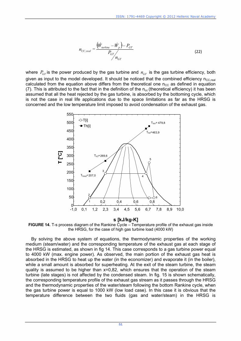
FIGURE 14. T-s process diagram of the Rankine Cycle � Temperature profile of the exhaust gas inside
the HRSG, for the case of high gas turbine load (4000 kW) By solving the above system of equations, the thermodynamic properties of the working
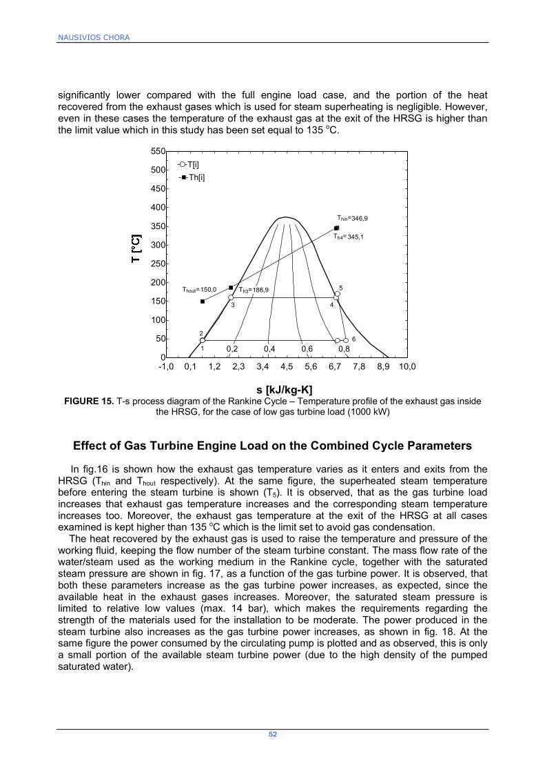
medium (steam/water) and the corresponding temperature of the exhaust gas at each stage of the HRSG is estimated, as shown in fig 14. This case corresponds to a gas turbine power equal to 4000 kW (max. engine power). As observed, the main portion of the exhaust gas heat is absorbed in the HRSG to heat up the water (in the economizer) and evaporate it (in the boiler), while a small amount is absorbed for superheating. At the exit of the steam turbine, the steam quality is assumed to be higher than x=0,82, which ensures that the operation of the steam turbine (late stages) is not affected by the condensed steam. In fig. 15 is shown schematically, the corresponding temperature profile of the exhaust gas stream as it passes through the HRSG and the thermodynamic properties of the water/steam following the bottom Rankine cycle, when the gas turbine power is equal to 1000 kW (low load case). In this case it is obvious that the temperature difference between the two fluids (gas and water/steam) in the HRSG is
NAUSIVIOS CHORA
52
significantly lower compared with the full engine load case, and the portion of the heat recovered from the exhaust gases which is used for steam superheating is negligible. However, even in these cases the temperature of the exhaust gas at the exit of the HRSG is higher than the limit value which in this study has been set equal to 135 oC.
-1,0 0,1 1,2 2,3 3,4 4,5 5,6 6,7 7,8 8,9 10,00
50
100
150
200
250
300
350
400
450
500
550
s [kJ/kg-K]
0,2 0,4 0,6 0,8
T[i]T[i]
1
2
3 4
6
5
Thin=
Th[i]Th[i]
Th4=
Th3=Thout=
346,9
345,1
186,9150,0
FIGURE 15. T-s process diagram of the Rankine Cycle � Temperature profile of the exhaust gas inside
the HRSG, for the case of low gas turbine load (1000 kW)
Effect of Gas Turbine Engine Load on the Combined Cycle Parameters
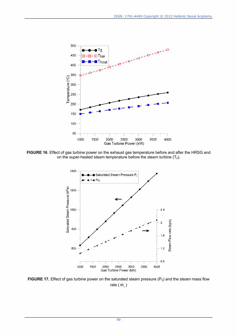
In fig.16 is shown how the exhaust gas temperature varies as it enters and exits from the HRSG (Thin and Thout respectively). At the same figure, the superheated steam temperature before entering the steam turbine is shown (T5). It is observed, that as the gas turbine load increases that exhaust gas temperature increases and the corresponding steam temperature increases too. Moreover, the exhaust gas temperature at the exit of the HRSG at all cases examined is kept higher than 135 oC which is the limit set to avoid gas condensation.
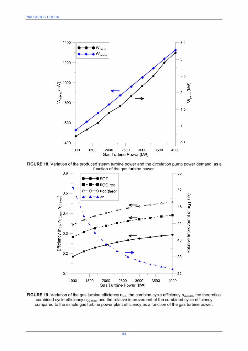
The heat recovered by the exhaust gas is used to raise the temperature and pressure of the working fluid, keeping the flow number of the steam turbine constant. The mass flow rate of the water/steam used as the working medium in the Rankine cycle, together with the saturated steam pressure are shown in fig. 17, as a function of the gas turbine power. It is observed, that both these parameters increase as the gas turbine power increases, as expected, since the available heat in the exhaust gases increases. Moreover, the saturated steam pressure is limited to relative low values (max. 14 bar), which makes the requirements regarding the strength of the materials used for the installation to be moderate. The power produced in the steam turbine also increases as the gas turbine power increases, as shown in fig. 18. At the same figure the power consumed by the circulating pump is plotted and as observed, this is only a small portion of the available steam turbine power (due to the high density of the pumped saturated water).
ISSN: 1791-4469 Copyright © 2012 Hellenic Naval Academy
53
FIGURE 16. Effect of gas turbine power on the exhaust gas temperature before and after the HRSG and on the super-heated steam temperature before the steam turbine (T5).
FIGURE 17. Effect of gas turbine power on the saturated steam pressure (P5) and the steam mass flow rate ( cm )
NAUSIVIOS CHORA
54
FIGURE 18. Variation of the produced steam turbine power and the circulation pump power demand, as a function of the gas turbine power.
FIGURE 19. Variation of the gas turbine efficiency nGT, the combine cycle efficiency nCC,real, the theoretical combined cycle efficiency nCC,theor and the relative improvement of the combined cycle efficiency compared to the simple gas turbine power plant efficiency as a function of the gas turbine power.

ISSN: 1791-4469 Copyright © 2012 Hellenic Naval Academy
55
In fig. 19 it is shown a comparison between the initial gas turbine efficiency nGT and the one obtained using the proposed combined cycle configuration nCC,real at all the range of operating conditions examined (Gas turbine power from 1000 kW to 4000 kW). As observed, the combined cycle efficiency is significantly higher than the one of the simple gas turbine, ranging from 28%÷39%, while being higher at high engine loads. At the same figure, the theoretical efficiency of the combined cycle nCC,theor is shown, as being calculated using equation (7). It is observed that if there were no restrictions regarding the size of the heat exchangers and the outlet temperature of the exhaust gases, it would be (theoretically) possible to further increase the benefit obtained using the combined cycle, and the combined cycle efficiency could range from 34%÷46%. However, even with the conservative configuration of the combined cycle which has been examined, the relative improvement on the gas turbine thermal efficiency ranges from 53% at low load to 33% at high load (as shown in fig. 19), which is very challenging. It is noticed that the greater improvement is observed at low load conditions where the thermal efficiency of the gas turbine is lower. This is very important for the marine applications since a significant portion of the vessel�s duty is spent at low load conditions.
CONLUSIONS
In the present work, a parametric investigation has been conducted, to investigate the possible improvement on the combined cycle efficiency and the corresponding net power production, which can be obtained by adding a bottoming Rankine cycle with a steam turbine on an existing gas turbine engine which is used for propulsion on a combatant vessel of the Hellenic Navy. To this scope a simple model has been developed based on the conservation of energy, for the Rankine cycle simulation and the HRSG. From this preliminary study, it has been concluded that such a combined cycle configuration, could offer significant improvement on the combined cycle engine efficiency, while at the same time, it is accompanied with a significant increase on the net available power and a corresponding decrease on the exhaust gas temperature. These findings are challenging and indicative of the potential benefit (economic and tactical) which could be obtained for the Hellenic Navy by adopting such techniques. However, a more detailed investigation should be conducted, regarding mainly the heat transfer processes at the HRSG and the condenser, to ensure that the required volume and weight of this installation is affordable based on the specific needs of the vessel.
REFERENCES
1. Horlock JH. Combined power plants, including combined cycle gas turbine (CCGT) plants. Malabar, Florida: Krieger Publishing Company; 2002
2.Fredrik Haglind, �A review on the use of gas and steam turbine combined cycles as prime movers for large ships. Part I: Background and design�, Energy Conversion and Management 49 (2008) 3458�3467
3. Kehlhofer RH, Warner J, Nielsen H, Bachmann R. Combined-cycle gas and steam turbine power plants. 2nd ed. Tulsa, Oklahoma: PennWell; 1999
4. Merz CA, Pakula TJ. The design and operational characteristics of a combined cycle marine power plant. ASME paper 72-GT-90, 1972
5. Mills RG. Greater ship capability and energy saving with combined-cycle machinery. Nav Eng J 1977;89:17�25
6. MAN B&W Diesel A/S.:Waste Heat Recovery Systems. Copenhagen Denmark, 2007 7. WARTSILA Diesel A/S.:Energy savings and environmental benets via Exhaust Gas Heat Recovery 8. V. Ganapathy , �Heat-Recovery Steam Generators: Understand the Basics�, CHEMICAL
ENGINEERING, August 1996 9. atsanos CO, Hountalas DT, Pariotis EG. Thermodynamic analysis of a Rankine cycle applied on a
diesel truck engine using steam and organic medium. Energy Convers Manage 2012;60:68�76.
NAUSIVIOS CHORA
56
10. Muench,R. K. ; Knauss,D. T. ; Purnell,J. G., �A study of waste-heat-boiler size and performance of a conceptual marine cogas system�, David W Taylor Naval Ship Research and Development Center Bethesda Md, Feb 1980
11. Fredrik Haglind, �A review on the use of gas and steam turbine combined cycles as prime movers for large ships. Part I: Background and design�, Energy Conversion and Management, Volume 49, Issue 12, December 2008, Pages 3458-3467, ISSN 0196-8904, 10.1016/j.enconman.2008.08.005
12. Roumeliotis I., Mathioudakis K., Aretakis N. �Performance analysis of twin-spool water injected gas turbines using adaptive modeling�, ASME paper No. GT2003-38516.
13. Stamatis A., Kamboukos Ph., Aretakis N., Mathioudakis K., 2002, �On Board Adaptive Models: A General Framework and Implementation Aspects,� ASME Paper No. GT-2002 -30622.
14. Stamatis A., Mathioudakis K., Papailiou D.K., 1990, �Adaptive Simulation of Gas Turbine Performance,� ASME J Eng Gas Turbines Power, 112(2), pp. 168-175
15. Tsalavoutas ., S. Pothos, Mathioudakis K., Stamatis A., 1999, �Monitoring the performance of a twin-spool ship propulsion turbine by means of adaptive modeling,� RTO Symposium on Gas Turbine Operation and Technology for Land, Sea and Air Propulsion and Power Systems, Ottawa, Canada, 18-21 October 1999.
16. Petry, B. R., "Acid Dew-Point Determination for Gas Turbine, Waste Heat Recovery Units," DTNSRDC Report PAS-77-29, Mar 1978
17. Kays, W. M- and A. L. London, �Compact Heat Exchangers�, McGraw-Hill, 1964 18. Petry, B. R., "Acid Dew-Point Determination for Gas Turbine, Waste Heat Recovery Units,"
DTNSRDC Report PAS-77-29, Mar 1978 19. William G. Steltz , Book chapter �26. STEAM TURBINES�, Mechanical Engineers� Handbook: Energy
and Power, Volume 4, Third Edition, Edited by Myer Kutz, by John Wiley & Sons, Inc