feasibility of underground pneumatic freight transport in ... ny.pdf · of pneumatic capsule...
TRANSCRIPT

Feasibility of Underground Pneumatic Freight Transport in New York City
Final Report
Prepared for The New York State Energy Research and Development Authority
(NYSERDA) Albany, NY
Frank Ralbovsky, Project Manager
Prepared by Henry Liu, Ph.D., P.E.
Freight Pipeline Company Columbia, Missouri
Project Manager
NYSERDA Agreement No. 7643 August 1, 2004

ii
NOTICE
This report was prepared by Freight Pipeline Company in the course of performing work contracted for and sponsored by the New York State Energy Research and Development Authority (hereafter “NYSERDA). The opinions expressed in this report do not necessarily reflect those of NYSERDA or the State of New York, and reference to any specific product, service, process, or method does not constitute an implied or expressed recommendation or endorsement of it. Further, NYSERDA, the State of New York, and the contractor make no warranties or representations, expressed or implied, as to the fitness for particular purpose or merchantability of any product, apparatus, or service, or the usefulness, completeness, or accuracy of any processes, methods, or other information contained, described, disclosed, or referred to in this report. NYSERDA, the State of New York, and the contractor make no representation that the use of any product, apparatus, process, method, or other information will not infringe privately owned rights and will assume no liability for any loss, injury, or damage resulting from, or occurring in connection with, the use of information contained, described, disclosed, or referred to in this report.

iii
SUMMARY The purpose of this project is to investigate the feasibility of using the modern technology of pneumatic capsule pipeline (PCP), which has been used successfully in Japan, for underground freight transport in New York City. Through a detailed assessment of the technology development, it was found that twin lines of PCPs of various sizes and of both round and rectangular cross-sections can be used in New York City for a number of applications including but not limited to: (1) underground tunnel construction, (2) transportation of municipal solid wastes from transfer stations to a common out-of-state landfill/processing-recycling center, (3) transportation of mail and parcels from (to) the five boroughs of the City to (from) Washington D.C. and other cities along the route, (4) transporting pallet goods via a network of tunnels under New York City, (5) dispatching standard containers from (to) the container ports in New York City to (from) an inland station in rural area for inspection and intermodal transport, and (6) ferrying trucks across the Hunts Point peninsula to reduce traffic jam and air pollution caused by trucks serving the nation’s largest food processing center. It was found that all the aforementioned six potential applications are technically feasible by using well-proven technologies such as PCP, blowers, linear induction motors, tunnel boring machines, microtunneling, horizontal directional drilling, barcodes, and radio-frequency identification (RFID), etc. The cost of each application has also been assessed and compared with the current cost of using trucks for the same purpose. It was found that the first five of the six potential applications are more cost-effective than using trucks. In all these five cases, great savings can be accomplished by using PCP instead of trucks. The sixth potential application (i.e., the Hunts Point project) is the only one found to be uneconomical. Even so, the project can still be justified for its social and environmental benefits to the residents of Hunts Point and Bronx. The fifth application (i.e., the container dispatch PCP), is shown to have great values for port security, and hence can be justified on either security or economic grounds, or both. All six applications were found to have great value for reducing air pollution, traffic jams, and accidents caused by trucks, and for economic development of the New York City. Should these six potential applications be fully implemented in the future, New York City could expect a reduction of truck usage by as much as 70%, which would greatly benefit the City in a number of ways. In conclusion, this study finds that the new technology of PCP is both technically and environmentally feasible for a variety of usages in New York City, and future use of this new technology can drastically cut the number of trucks needed to enter the City, resulting in reduced traffic jam, accidents and air pollution, enhanced transportation safety and security, and economic development -- creation of a new industry and a great number of new jobs in the City. Because PCP uses electricity instead of diesel fuel, the use of PCP in New York City also reduces the consumption of imported oil. This report provides detailed analysis and justification for the beneficial use of PCP in New York City, and provides a blueprint for implementation. The study was sponsored by the New York State Energy Research and Development Authority (NYSERDA).
KEY WORDS
Capsule pipeline, freight pipeline, freight transport, New York City, pallet freight, pneumatic capsule pipeline, port security, traffic jam, tunneling cost, underground freight transport.

iv
ACKNOWLEDGMENT
This project was sponsored by the New York State Energy Research and Development Authority (NYSERDA). Frank S. Ralbovsky served as the Project Manager representing NYSERDA. His strong support to the project, close monitoring of project activities, and providing valuable suggestions and information greatly facilitated the study. The success of this project also depended on other organizations and individuals, especially those who served on the Stakeholders Committee of the project. They include Steve Brown of the Port Authority of NY & NJ (PANYNJ), Joseph Littmann of the NYSERDA’s Regional Office in New York City, Howard J. Mann of the New York Metropolitan Transportation Council (NYMTC), Scott North of the American Pipeliners Union Local 798, Michelle S. Pak of the New York City Economic Development Corporation (NYCEDC), Kailash Sharma of the NYC Department of Environmental Protection (NYCDEP), and Kuang H. Teng of the U.S. Postal Service (USPS). Two private companies have provided extensive free consulting to the project. They are Accu-Sort Systems, Inc. in Pennsylvania (represented by T.J. Tarrant), and Sumitomo Metal Industries (SMI), Ltd. in Japan (represented by Sainai Kosugi). Accu-Sort specializes in and provided service on identification/sorting systems. SMI being the world’s leading company in pneumatic capsule pipeline (PCP) provided key information on PCP. The project also received extensive and excellent consulting services from Professor M. Najafi, Director, Center for Underground Infrastructure Research and Education (CUIRE), Michigan State University. The service provided are related to the construction methods and cost for installing PCP. To explore the possibility of using PCP for transporting foods to and from Hunts Point, the following individuals provided significant help: Myra Gordon of the Hunts Point Produce Market, the nation’s largest produce market, provided key information on the operation of the market; Bruce Reingold and his staff at the Hunts Point Cooperative Market, the nation’s largest meat market, provided key information on the market; and Tom Susseewell of NYCEDC helped to arrange visits with these markets. In addition, several officials of NYCDEP provided valuable help or information: Burjor Khariwala provided key information on the tunneling cost in New York City, and the depth of Water Tunnel No.2 through Hunts Point; Vincent J. Soriano provided key information on the location and depth of water mains in Hunts Point; Frank Kulcsar and Stella Rozelman provided information on the waste treatment facility in Hunts Point; and Yefim Shapiro made available maps of sewers in Hunts Point. These maps were examined by Tsau-Lin Chen, an engineer in New York City who helped the project. Finally, my wife Susie who is a CPA managed the business and fiscal aspects of the project, enabling me to focus on technical matters. Many thanks to all the people and organizations mentioned above!
Henry Liu, P.E., Ph.D. Principal Investigator
Freight Pipeline Company 2601 Maguire Boulevard
Columbia, MO 65201-8253 Phone: 573-442-0080
E-Mail: [email protected]

v
TABLE OF CONTENTS Section Page COVER ………………………………………………………………………………… i NOTICE ………………………………………………………………………………... ii SUMMARY …………………………………………………………………………….. iii KEY WORDS …………………………………………………………………………. iii ACKNOWLEDGMENT ………………………………………………………………. iv TABLE OF CONTENT ……………………………………………………………….. v 1. INTRODUCTION …………………………………………………………………. 1 1.1 Problem Statement ……………………………………………………………... 1 1.2 Solution to Problem ………………………….………………………………… 1 1.3 Purpose of Project and Scope of Work …………………………………………. 2 1.4 Technology Description ………………………………………………………… 2 1.5 Current R & D ……………………………………………….…………….……. 3 1.6 Relation to Regional Transportation Plan ……………………………………… 4 1.7 Comparison to Alternative Solutions ………………………………………….. 4 1.8 Summary of Benefits to New York City ……………………………………….. 4 2. POTENTIAL APPLICATIONS TO NEW YORK CITY …………………………… 6 2.1 Tunnel Construction ………………………………………………………….... 6 2.2 Transporting Palleted and Other Goods (Pallet-Tube System) ………………… 9 2.3 Dispatching Containers ………………………………………………………… 13 2.4 Truck Ferry PCP System ………………………………………………………. 17 2.5 Other Potential Applications ……………………………………………………. 21 (a) Solid Waste Transport ……………………………………………………… 21 (b) Mail and Parcel Transport …………………………………………………… 23 (c) Use of Existing Right-of-Ways ………………………………………………. 26 3. TECHNOLOGY ASSESSMENT ………………………………………………….. 28 3.1 Pneumatic Capsule Pipeline (PCP) ……………………………………………. 28
(a) Difference between PCP and Tube Transport …………………………….. 28 (b) Readiness of the PCP Technology for Use in New York City ……………. 28 (c) Wheels of PCP Capsules ………………………………………………….. 29 (d) Capsule Trains ……………………………………………………………. 30 (e) Key Equations for System Design ……………………………………….. 30 (f) Brakes for Capsules ………………………………………………………. 32 (g) Drive Types ………………………………………………………………. 32 (h) Operation of PCP Systems …………………………………………………. 33 (i) Maintenance of PCP Systems …………………………………………….. 33 3.2 Linear Induction Motor (LIM) ………………………………………………… 34
(a) Basic Concept ……………………………………………………………. 34 (b) LIM versus LSM …………………………………………………………. 34 (c) Planar versus Tubular LIMs ……………………………………………… 35 (d) LIMs for PCP Applications in New York City …………………………... 36
(e) Readiness of the LIM Technology for Use in PCPs ……………………... 36

vi
3.3 Vertical Capsule Transport (Capsule Lift) …………………………………….. 38 3.4 Capsule Identification and Sorting …………………………………………….. 39 (a) Barcode ……………………………………………………………………. 40 (b) RFID System ………………………………………………………………. 40 3.5 Construction (Digging/Pipe-Laying) Methods …………………………………. 41 (a) Tunneling Technology …………………………………………………….. 41 (b) Open-Cut Method …………………………………………………………. 42 (c) Microtunneling …………………………………………………………….. 44 (d) Horizontal Directional Drilling ……………………………………………. 44 (e) Marine Pipeline Construction ……………………………………………… 45 3.6 Technology Readiness for Use in New York City …………………………….. 46 4. ECONOMIC ASSESSMENT ……………………………………………………… 47 4.1 Tunnel Construction ……………………………………………………………. 47 4.2 Solid Waste Transport ………………………………………………………….. 48 4.3 Mail and Parcel Transport ……………………………………………………… 50 4.4 Pallet-Tube PCP ……………………………………………………………… 51 4.5 Container Dispatch PCP …………………………………………………….. 52 4.6 Truck-Ferrying PCP in Hunts Point …………………………………………. 55 5. BENEFITS ASSESSMENT ………………………………………………………. 57 5.1 Methodology Used for Assessing External Benefits …………………………. 57 5.2 External Benefits of Each Potential PCP Application ………………………... 58 (a) Tunnel Construction ……………………………………………………….. 58 (b) Solid Waste Transport …………………………………………………….. 59 (c) Mail and Parcel Transport ………………………………………………… 60 (d) Pallet-Tube PCP …………………………………………………………... 61 (e) Container Dispatch PCP …………………………………………………… 62 (f) Truck-Ferrying PCP in Hunts Point ……………………………………….. 63 6. CONCLUSIONS AND RECOMMENDATIONS ……………………………….. 64 6.1 Conclusions .…………………………………………………………………… 64 6.2 Recommendations …………………………………………………………….. 66 APPENDICES: ……………………………………………………………………… 68 A. REFERENCES ………………………………………………………………... 69 B. ENGINEERING CALCULATIONS …………………………………………... 73 B.1 PCP for Tunnel Construction ……………………………………………… 73 B.2 PCP for Transporting Solid Wastes ……………………………………… 75 B.3 PCP for Transporting Mail and Parcels ………………………………….. 78 B.4 Pallet-Tube PCP System ………………………………………………… 80 B.5 Container-Dispatch PCP ……………………………………………….… 83 B.6 Truck-Ferry PCP in Hunts Point ………………………………………… 86

vii
C. CONSTRUCTION COST OF PCP……………………………………………….. 88 C.1 Tunneling Cost in New York City ………………………………………….. 88 C.2 Cost of Large Rectangular Reinforced Conduits Laid in Trenches ………… 90 C.3 Cost of Steel Pipelines Laid in Trenches (Open-Cut Method) ……………... 91 C.4 Cost of Laying Submarine Pipelines ………………………………………… 92 C.5 Cost of Microtunneling and Horizontal Directional Drilling (HDD) ….……... 92

1
INTRODUCTION
1.1 PROBLEM STATEMENT New York City, being one of the largest cities in the world, suffers from severe traffic congestion on streets and highways. The congestion hurts the City in many ways including: (1) loss of productivity due to extra time spent in travel to and from work by passengers and delays in freight movement through the City; (2) accidents caused by vehicles (trucks and cars) that clog the streets and highways, which in turn cause death and injury to individuals on the street and damage to properties (vehicles); (3) waste of energy (diesel fuel) by trucks tied down in the slow-moving traffic on the City’s streets, (4) noise caused by cars and trucks on congested streets; (5) air pollution caused by cars and trucks tied down in traffic jams and moving slowly through streets and highways; (6) increased security risks due to the possible use of trucks or cars as bombs by terrorists as happened to the World Trade Center in 1993, and the difficulty in evacuation of people and vehicles from congested streets following any terrorist attack. The aforementioned transportation problems are highly detrimental not only to New York City and New York State, but also to the rest of the nation and the world, due to the large number of tourists from other states and countries visiting New York City each day. Even for those U.S. citizens who do not visit New York City, this is an important issue because of their kinship to and patriotic feelings toward New York as demonstrated by the enormous outpour of concern and sympathy from across the nation following the September 11 terrorist attack, and because of state and national revenues (state and federal taxes) spent on the City. Therefore, reduced traffic congestion on the streets and highways of New York City is important to the City, the State of New York, the nation and even the world. 1.2 SOLUTION TO PROBLEM
A multiple of approaches and technologies must be used to solve New York City’s transportation problems. The approaches include increased use of bicycles, increased use of mass transit, increased use of rail for passenger and freight transport, limiting truck delivery to off-peak-traffic hours, reduced time for street repair which blocks traffic, building additional tunnels across the Hudson River to alleviate traffic to and from New Jersey and so forth. New technologies should also be mobilized to help solve the problem. They include the use of intelligent transportation systems (ITS), more efficient and less polluting automobiles, increased use of trenchless technologies for the construction and repair of underground infrastructures including sewers, utility lines, fiber optics, etc. [1]. Pneumatic capsule pipeline (PCP) is an important new technology currently not used or considered by transportation authorities and transportation planners for solving the aforementioned traffic congestion problem in New York City and in other cities in the nation. This new technology has not been used nor considered for use because only a handful of transportation professionals know what PCP is and what it can do. Even fewer know how to design it. New York City is the most appropriate city in the United States to consider this new technology, not only due to the severe traffic congestion problem that exists in the City, but also due to the great potential that this new technology has in energy conservation, reducing air and noise pollution, and enhancing the City’s ability to cope with future terrorist attacks. Besides, New York City has extensive experience in using underground tunnels for subways, highways, sewers and utility lines, unmatched by other cities in the nation. Such experience facilitates trenchless construction of underground PCP systems.

2
1.3 PURPOSE OF PROJECT AND SCOPE OF WORK The purpose of this research project is to evaluate the feasibility of using the modern PCP technology and other complimentary enabling new technologies for possible use in New York City for underground freight transport, as a means to reduce the City’s reliance on trucks and to alleviate the City’s traffic-related problems. Both the technical and economic feasibilities of using PCPs in New York City are addressed. Social and environmental benefits that can be derived from using PCP for freight transport in New York City are also analyzed. The scope of work of the project includes: (1) a detailed assessment of the modern technologies needed for using PCPs in New York City, (2) identifying and planning various potential applications of PCPs in New York City, (3) analysis and preliminary design of the PCP system involved in each proposed application, (4) a determination of the approximate cost and the cost effectiveness of each proposed application, and (5) analysis of the environmental and social benefits of each proposed application. The study provides the basic information needed for transportation planners in New York City and New York State to make detailed plans for implementing the most advanced PCP systems in the City for the benefit of its eight million residents. 1.4 TECHNOLOGY DESCRIPTION PCP (Pneumatic Capsule Pipeline) is the modern and high-tech version of the “pneumatic tubes” used over half a century ago in New York City and many other major cities around the world for underground transportation of mail, parcels and many other goods [2]. The current advanced PCP systems, used successfully in Japan [3, 4], utilize wheeled capsules (vehicles) to transport freight through large-diameter underground pipes of the order of 1-meter diameter. Air is blown through the pipe to move the capsules. The system can transport hundreds of cargoes—anything of a size smaller than the pipe diameter. By using modern technology such as high-speed computers and special scanners, the system is highly automated and efficient. Two types of PCP have been developed and used successfully in Japan, one using circular pipes and the other using rectangular conduits—see respectively (a) and (b) in Figure 1 below.
(a) Round (circular) PCP (b) Rectangular or square PCP Figure 1. Pneumatic capsule pipeline (PCP) systems developed by and Used in Japan (Courtesy of Sumitomo Metal Industries, Ltd.) In this study, both the circular and the rectangular types of PCP have been considered for possible use in New York City. The circular type is more suitable for smaller diameter PCPs that use pipes up to approximately 1 m (3.28 ft) in diameter to transport small objects such as crushed minerals, mail, small parcels, groceries and solid waste (garbage). On the other hand, the

3
rectangular type, using conduits of approximately 1 m by 1 m or larger cross sections, is for transporting packaged large objects including boxes, creates and pallets. As will be seen later in this report, large objects such as the containers carried by trucks, and even the trucks themselves, can be transported by PCPs of very large cross section. This study also explored a third configuration of PCP: a hybrid system that uses box-shape capsules moving in underground tunnels of circular cross sections. This hybrid system is practical only for underground tunnels of circular cross sections, constructed by using modern tunnel boring machines, which result in tunnels of circular cross sections. This research project uses a novel concept or approach to solve traffic congestion and security problems in large cities—an approach hitherto not seriously considered or studied by any transportation agency in the United States. The study is innovative because of the new technologies used in designing and planning the best system of PCPs for New York City. These new technologies include the most modern and advanced PCP systems used only in Japan so far [3, 4], an electromagnetic pump (linear induction motor) which is an improved capsule propulsion system developed recently at the Capsule Pipeline Research Center (CPRC)1 of the University of Missouri [5], trenchless technologies for constructing PCPs [1], and use of RFID (Radio Frequency Identification) systems and other modern high-tech equipment for monitoring and automatic control of PCP systems [6]. Success in this study enables the New York City to use the most advanced PCP systems in the world for future freight transport, benefiting the City and the State. 1.5 CURRENT R & D Current R&D in PCP is centered in Japan. The Sumitomo Metal Industries, Ltd. in Japan has developed and used PCPs of both round and rectangular cross-sections for transporting minerals [3], for constructing long tunnels for bullet trains [4], and for highway-related projects [4]. The Company’s current effort is focused on developing and using a vertical PCP system to transport and dispose of solid waste deep underground [7], and ways to improve current systems used in Japan. In the United States, research in PCP exists in three places: (1) The Capsule Pipeline Research Center (CPRC) at the University of Missouri-Columbia is studying the use of linear induction motor (LIM) to power PCP [5]. Note that LIM is the same technology used for powering magnetically levitated high-speed trains, and for accelerating modern roller coasters. The current PCP systems use blowers (fans) to blow air through pipes; the moving air in turn propels the capsules. Use of LIMs instead of blowers to propel capsules has many advantages such as it simplifies the PCP system design, reduces system costs, and enables capsules to move through pipes of any slope, including vertical. (2) Researchers at the University of Minnesota are also studying the use of LIM to power large diameter capsules in conduits imbedded under highways for future freight transport [8]. (3) Another recent research initiative in PCP is a project to use a linear synchronous motor, which is a technology similar to LIM, to power a PCP for transporting phosphate ore [9]. The project was sponsored by the Florida Phosphate Research Institute. Finally, at present (2004) Freight Pipeline Company in Columbia, Missouri, is undertaking R & D sponsored by the U. S. Department of Energy, to develop an advanced PCP system based on LIM specifically for conveying minerals and mine wastes [10]. 1 CPRC was established in 1991 by the National Science Foundation (NSF) as a State/Industry University Cooperation Research Center (State/IUCRC), and was supported by NSF until 2000.

4
1.6 RELATION TO REGIONAL TRANSPORTATION PLAN The future of NYC’s transportation is governed by the Regional Transportation Plan. The current (1999) version of the Plan places emphasis on managing demand and focusing on alternative modes of transportation, such as transit, walking, bicycling, ferry service, ridesharing (carpooling), and helping people to make smarter travel choices through the application of new intelligent transportation systems (ITS) technologies. The plan also cites the undesirable increase in the number of trucks for freight transport in the Region, and proposes various measures to reverse the trend, such as by constructing a dedicated rail freight tunnel across the Hudson River, and/or reactivation of the Poughbeepsie Railroad Bridge. This shows that the solution to NYC’s transportation problem, as proposed in this study, is consistent with the approaches used in the Regional Transportation Plan even though PCP was not mentioned in it. It is believed that PCP was not mentioned in the 1999 Plan because this technology, being very new, was insufficiently known to the planners of the 1999 Plan. Besides, no study to confirm the technical and economic feasibility of using PCP in New York City had been conducted prior to that time. The Regional Transportation Plan is a document updated every three years. However, due to the September 11, 2001 attack on the World Trade Center, the 2002 Plan was disrupted and suspended. At present, the New York Metropolitan Transportation Council (NYNTC) is preparing for a new plan for publication in 2005. With the completion of this feasibility study in 2004 and with the promising findings of technical and economic feasibility and great potential benefits of PCP to NYC, it is reasonable to expect that the new technology of PCP will be addressed in the 2005 version of the Regional Transportation Plan. 1.7 COMPARISON TO ALTERNATIVE SOLUTIONS
Alternative solutions to the traffic jam and the related noise and air pollution problems in New York City include: more use of bicycles and mass transit, more rails for passenger and freight transport, use of intelligent transportation systems (ITS), better planning for new developments, faster repair of streets, improved coordination between various agencies dealing with constructions and other activities (such as trash pickup) that affect traffic, etc. All these measures contribute to solving New York City’s problem, and should be implemented in order to provide greatest benefits to New York City. The proposed solution is not meant to replace any of these alternative solutions. Rather, it constitutes an additional and effective new means to alleviate New York City’s transportation problem—a new solution hitherto unrecognized by the public and even by transportation planners of the State and the nation. A full implementation of the potential applications of PCP in New York City in the future is expected to result in at least a 70% reduction in the use of trucks for freight transport in the City. It constitutes the most effective known means to reduce the use of trucks in New York City.
1.8 SUMMARY OF BENEFITS TO NEW YORK CITY Implementation of the various potential applications of PCPs in New York City as discussed in this report will benefit the City and the State in the following manners:
(1) Drastic reduction in the need for trucks and the number of trucks that clog the City’s streets. (2) Drastic reduction in air pollution, noise and accidents generated by trucks. (3) More rapid delivery of goods than currently possible by trucks on congested streets. (4) Greater reliability in freight delivery—because PCPs are unaffected by inclement weather,
traffic jams and road/street repairs.

5
(5) Conservation of energy—PCP uses much less energy than trucks use in congested cities where trucks cannot operate efficiently due to traffic jams.
(6) Reduced reliance on foreign oil—while trucks uses diesel fuel, PCP uses electricity, which can be supplied by domestic energy sources, including renewable sources.
(7) Increased security—Goods to be delivered by PCPs cannot be stolen as easily as those transported by trucks. Terrorists cannot hijack the vehicles (capsules enclosed in an underground pipeline) and use them as car bombs or truck bombs. Also, it is far more difficult for terrorists to attack an underground PCP and inflict catastrophic damage to it than to an aboveground structure such as a building or a bridge. Unlike aboveground structures, which are readily accessible by terrorists and difficult to guard against their attacks, underground PCPs are inaccessible to people except at the inlet and outlet and hence can be more easily guarded against any attack or sabotage. Furthermore, because using PCPs will result in fewer trucks clogging the streets, residents can be evacuated more readily in the event of any emergency.
(8) Economic development and creation of jobs—Future use of PCPs in New York City will create a large number of jobs in NYC and NYS—not only engineering and construction jobs during the construction of PCPs, but also permanent jobs for running and operating the new system. Furthermore, many materials and equipment used for constructing PCPs will come from existing as well as new companies based in New York State. Because New York will lead the nation in using the PCP technology, it is anticipated that a new industry will be generated in and around NYS for the supply of the equipment, parts and engineering services needed for the rest of the nation to build PCPs in various congested cities and regions across the nation. This will bring huge and lasting benefits to NYS and NYC.
An attempt will be made later in Section 5 BENEFIT ASSESSMENT to quantify some of the foregoing benefits for each of the six potential applications to New York City.
6
Section 2 POTENTIAL APPLICATIONS TO NEW YORK CITY
Various potential applications of the PCP technology to New York City have been considered and evaluated in this study. They are first described in this section, and later (in the ensuing sections) assessed for their technical and economic feasibility. 2.1 TUNNEL CONSTRUCTION New York City has a large number of underground tunnels constructed for various purposes including water supply, sewers, mass transit, highway, rail, gas and petroleum pipelines, and cables – including power cables, telephone cables, and TV cables. A good discussion of these tunnels and related underground infrastructures can be found in a number of documents including books such as [11], and Internet articles such as [12]. Some tunnels, such as Water Tunnel No.3, are under construction and will take until year 2020 to complete [13]. Also, there is an increasing need for constructing other underground tunnels in New York City for various purposes, such as the tunnels for a proposed rail system for freight [14], and a new rail system for passengers just announced by Governor George E. Pataki [15]. In the construction of large tunnels, such as Water Tunnel No. 3 which is 20 to 24 ft in diameter, trucks are used to transport construction materials into the tunnel and to transport excavated materials out of the tunnels. Because these tunnels are over 100 m underground, trucks are lowered into the tunnels and hoisted out through large vertical shafts. Using trucks for such tunnel construction is cumbersome and expensive. Besides, it causes serious safety and pollution problems both inside the tunnels and outside the tunnels near their entrances. According to [13], since 1970, twenty-four workers have lost their lives in accidents related to constructing Water Tunnel No. 3. Such tragedies and air and noise problems can be prevented or greatly reduced in the future by using PCP for conveying materials during tunnel construction, as it was done in Japan for constructing the Akima Tunnel shown in Figure 2. The Akima tunnel is one of the world’s longest rail tunnels constructed in Japan in 1997 for bullet trains. The tunnel is 8.3 km (5.2-mile) long and has a cross sectional area of 90 m2 (968 ft2) approximately, for accommodating a 2-track railroad. Figure 2 (a) is a photo of the tunnel when it was first completed but before the PCP was dismantled and the railroad was constructed through the tunnel. The PCP was made of prestressed concrete panels and was used for transporting premixed concrete into the tunnel for tunnel lining, and transporting excavated materials out of the tunnel for disposal. The PCP extended outside the tunnel for about 3 km (see Figure 2 (b)) so that the excavated materials generated by the tunnel boring machine (TBM) could be transported to a nearby dump site without using other transportation means such as trucks or conveyors. The type of capsules used in this PCP is shown in Figure 3. Note that feeding of construction materials such as premixed concrete into each capsule is through the open top of the capsule, whereas discharging the materials is by opening the bottom gates of the capsules. By extending the PCP conduit to the dump site, the excavated materials are discharged directly by capsules reaching the dump site – see Figure 4.

7
1 m × 1 m PCP
(a) Tunnel entrance
(b) PCP extending outside the tunnel to the dump site
Figure 2. Use of a rectangular PCP for constructing the Akima Rail Tunnel in Japan (Courtesy of Sumitomo Metal Industries, Ltd.)
Figure 3 A capsule used in the PCP for constructing the Akima tunnel in Japan.
(Courtesy of Sumitomo Metal Industries, Ltd.)

8
Figure 4 Capsules reaching the end of the Akima PCP to discharge their load at the dump site (Courtesy of the Sumitomo Metal Industries, Ltd.) The Japanese experience in using a PCP instead of rails or trucks for conveying materials during tunnel construction showed that the PCP system has a number of advantages including: (1) it has no moving part outside the pipe (conduit) and hence is extremely safe; (2) it is powered pneumatically, and hence it has no exhaust gas and causes no air pollution in the tunnel; (3) the PCP not only conveys capsules but also air, thereby serving a dual purpose – venting the tunnel while transporting solids; (4) the prime movers (i.e., the motor and the blower) are located outside the tunnel and hence do not take up the narrow space in the tunnel; and (5) the system transports materials at high speed and large quantity. For the Akima PCP, it transported excavated materials out the tunnel at the rate of 100 m3/hr (3529 ft3/hr). The only major limitation of the system is that the size of any article to be transported by PCP must be smaller than the size of the capsule opening, whose width is approximately 0.8 m or 30 inches, and length is approximately 3 m or 10 ft. Therefore, large construction materials or equipment cannot be moved in and out of the tunnel by using PCP; conventional vehicles are still needed for occasional movement of large materials and equipment in and out the tunnel. In spite of that, PCP was found to be the most cost effective way to convey the large amount of materials for constructing the Akima Tunnel. Much of the same PCP technology used successfully in Japan for constructing the Akima Tunnel can be used in New York City for constructing underground tunnels. The only main difference between the Akima Tunnel and New York City tunnels is that the former is a cross-mountains tunnel bored at ground level, whereas New York City tunnels are bored underground. However, this difference does not present any problem to using PCP for tunneling because capsules can be easily lifted and lowered vertically by using a conventional elevator (see Sec.3.3 Vertical Capsule Transport), or a pneumatic lift system reported in [7]. Either way, it is much easier and safer to lift/lower individual capsules than to lift/lower trucks. With tunnels being bored under busy city streets, the advantage of using PCP can be further expanded by extending the aboveground portion of the PCP conduit to a less crowded location away from tunnel entrances. In doing so, the truck traffic aboveground on busy streets near tunnel entrances can also be greatly reduced.

9
Note that blower-driven PCPs for tunnel construction are a proven technology. It can readily be used in NYC without having to do any research or demonstration. Through proper design, a blower-driven PCP of 1 m by 1 m cross-section has sufficient capacity (throughput) for handling the materials conveying needs of large tunnels up to about 10 m (33 ft) in diameter. Information on PCP design can be found in [16] and other publications, and hence is not repeated here. However, since this technology has not been used before in the United States for tunnel construction, it may be mutually beneficial to collaborate with experienced Japanese companies for the first use of such PCPs in New York City. This will also encourage Japanese investment in the underground infrastructures of the New York City. As will be shown later in Sec.4.1, using PCP for tunnel construction not only reduces pollution and saves lives, it also costs less than using trucks for the same purpose. 2.2 TRANSPORTING PALLETED AND OTHER GOODS (PALLET-TUBE SYSTEM) Most of the goods delivered by trucks in New York City come on pallets or in boxes, crates or bags. It would be highly desirable to design an underground PCP system that can transport such goods. Such a system shall hereafter be referred to simply as the “pallet-tube system.” Because a standard pallet in the United States is of the size of 40-inch (1.02 m) width and 48-inch (1.22 m) length, a rectangular capsule of approximate dimensions of 1.22 m (4 ft) width, 1.22 m ( 4 ft) height and 3.96 m (13 ft) length will be able to carry three fully loaded pallets. Such a capsule will also be able to carry most goods contained in boxes, creates or bags. Some longer capsules can also be used in the system to carry longer objects such as pipes in 20-ft lengths. Capsules like that can run through either a rectangular conduit having an approximate cross-section of 1.52 m (5 ft) by 1.52 (5 ft), or a circular conduit of approximately 2.13 m (7 ft) diameter having a flat floor – see Figure 5. The circular conduit is chosen for New York City because it is easier to construct underground by using a tunnel boring machine (TBM), and also because it is structurally stronger than rectangular cross section. As will be shown in Section 3.5, modern tunnel boring machines (TBM) are the best suited and most economic method for constructing tunnels such as those going through the hard bedrock underneath New York City. Such machines with large rotating cutters produce tunnels of circular cross section. To modify the tunnel cross section to other shapes requires significant extra costs. As can be seen from Figure 5, the standard capsule designed for the pallet-tube system for New York City uses steel wheels running on steel rails inside a circular tunnel that has a flat floor for the rails. This constitutes a main difference from the capsules used in Japan which use rubber tires. Steel wheels instead of rubber tires are chosen here for New York City for four reasons: (1) They have a rolling friction coefficient about 5 times smaller than that of rubber tires, thereby greatly reducing friction and saving energy; (2) capsules with steel wheels are much easier to control at branching points and in terminals, where standard railroad switching and control equipment can be used; (3) steel wheels are more wear-resistant than rubber tires, thereby minimizing wear and maintenance cost; (4) while capsules with rubber tires cannot run at high speed (more than 15 m/s) without damage caused by heat generation and temperature buildup in the tires, capsules using steel wheels can run at much higher speeds without temperature buildup. A disadvantage of using steel wheels instead of rubber tires is that noise is much higher for the former. However, this is not a serious drawback because most of the noise is generated and dissipated underground, disturbing nobody. The noise will be heard only when capsules are outside the pipe (conduit) and in a terminal (station). Even there, the noise is expected to be much less than what one hears at a subway or train station when a train passes by

10
or approaches the station. This is so because each capsule is much smaller and lighter than a train, and it does not emit any gas or steam because there is no powerhouse or engine on board of any capsule. The noise of PCPs comes mainly from contacts between the wheels and rails.
Figure 5 Cross-section of the pallet-tube PCP for New York City
Another main difference between the Japanese PCP systems and the pallet-tube PCP system is that the latter must use electromagnetic pumps instead of blowers. This is due to the complex network of conduits and the multiple inlets/outlets required for the pallet-tube system—a system similar to the current subway system in New York City. The most suitable electromagnetic pump for this application is single-sided linear induction motor (LIM) which will be discussed in detail in Section 3.2. The pallet-tube system considered here for New York City has a large number of node points (underground stations), with each located about 50 m or 150 ft under a City block but serving an entire neighborhood of blocks as shown in Figure 6. The dotted lines radiating out from the underground station in four directions are horizontal tunnels of 10-ft diameter with a flat floor for movement of goods from the station to neighboring streets, using either pallet jacks or small electric vehicles. Vertical elevators are used to lift the pallet jacks and small electric vehicles to the street level, and to lower them to the underground tunnel when they need to go back to the station. Such a system enables the delivery of goods to and from various parts of the City. Dual lines are needed to accommodate freight flow in opposite directions.
1.22 m (4 ft)
1.22 m (4 ft)
Capsule (steel)
Wheel (steel)
Rail (steel)
Concrete floor
Tunnel lining (shotcrete)
2.13 m (7 ft)
Drain pipe (horizontal) Drain (vertical)

11
Figure 6 A pallet-tube PCP station and outlet tunnels and elevators. (Note that the station and the tunnels are underground, connected to neighboring streets by elevators.) The layout (plan) of a typical pallet-tube station is shown in Figure 7. Each heavy dotted horizontal line in Figure 7 represents an approximately horizontal PCP conduit (the 7 ft diameter tunnel shown in Figure 5) imbedded in the bedrock approximately 50 m underground, and each heavy solid line represents a double-rail track on the floor of the station which is approximately 90 m underground. The station floor is kept approximately 5 m above the connected conduits so that gravity will cause the capsules to decelerate as they rise to the station platform (such as from S1 to S2), and to accelerate when injected into the line (such as from S3 to S4). Note that the PCP conduits and stations are to be placed deep underground in the bedrock in order to avoid interference with other underground structures such as building foundations, piles, sewers, water pipes, other pipelines, cables, and the subway system, which are normally found within 23 m (75 ft) of the ground surface in New York City. As shown in Figure 6, connection between each station and the streets above is by a set of four tunnels of 10 ft diameter, with their ends connected to the streets via elevators. Cargoes arriving at the station on pallets or in boxes, crates and bags can be transported by pallet jacks or battery-powered small vehicle moving through the tunnels, lifted to the street level by elevators, and then transported over short distances to neighboring stores along streets or side walks. A vertical cross section of the station is shown is Figure 8.
Streets
Elevators
Station
Tunnels

12
Figure 8 Sec.A-A (vertical cross section of a PCP station with layout shown in Fig.7) As shown in Figures 7 and 8, three parallel tracks are used on each side of the station floor for simultaneous loading/unloading of capsules. S1 through S8 are switches for rails, and L1 and L2 are LIMs which are needed only at locations where the capsules have reentered the conduits. Design of the LIMs can be done in a manner discussed in [6,17]. The cross-section of the LIM will be rectangular, having a width only 20 mm wider than the outer width of the capsule. The small clearance (gap) between the walls of the capsule and the LIM is necessary to achieve large thrust and good efficiency. Single-sided LIMs will be used. The capsule walls will be made of steel having a thin aluminum cladding 1 to 2 mm thick. The capsules used in such a system can be either single capsules or capsules mechanically linked as trains, similar to the linkage of ordinary railroad trains but with only a few capsules in each train. Using short trains instead of
Bedrock Exit tunnel (10 ft dia.) Exit tunnel
(10 ft dia.)
Bedrock
PCP twin tunnels (7 ft dia.)
16 ft
160 ft
Capsule trains Capsule trains
S1 S2 S3
S4
Station (underground)
S5 S6S7
S8 L1
L3
Figure 7 Layout (plan) of a typical underground station for the pallet-tube PCP
PCP conduitL4
L2 A
A

13
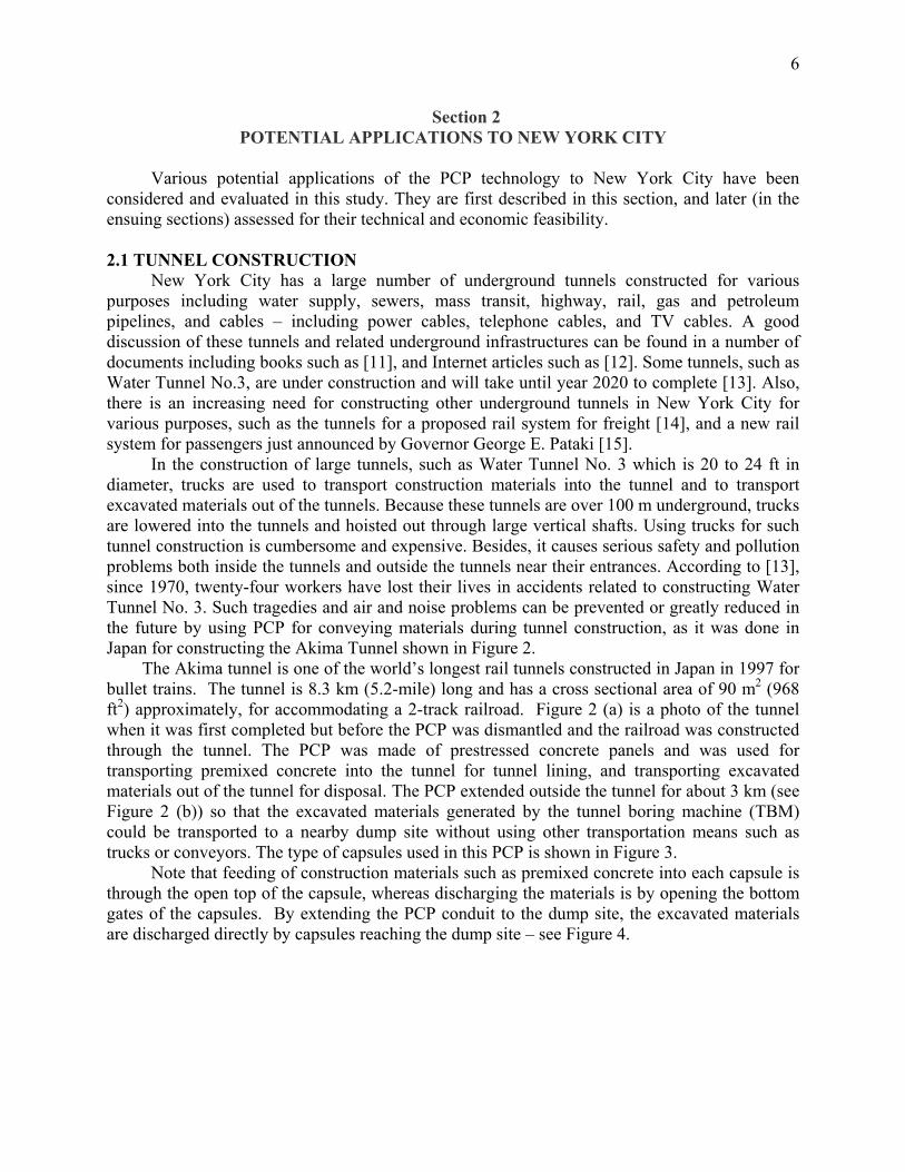
long trains not only reduces the length of each terminal station but also increases the frequency of goods delivery. A typical station shown in Figure 7 for 5-capsule trains will cover a floor space of be approximately 200 ft (length) × 160 ft (width). The pallet-tube PCP system can deliver most of the cargoes currently carried by trucks, including most cargoes inside large containers carried by tractor trailers. For such a system to work for a major city such as New York, it must use an extensive network of underground conduits having numerous inlet/outlet stations. The network should also have several intermodal freight transfer stations (“main stations” or “ports”) around the network’s outer perimeter, east of the Hudson River. At each port, trucks carrying freight headed for New York City will unload their cargoes from each container onto capsules in the port for dispatch through the underground pallet-tube network to various stations in New York City. The same trucks then return or leave the port with either empty containers, or containers loaded with a different cargo. Using such a system, trucks do not enter New York City, making the City a model for the world in freight transport. The same system can be used not only for freight transport but also for transporting municipal and industrial solid wastes generated inside New York City, for disposal or processing outside the City, by using special capsules assigned for transporting wastes. For a large city such as New York City, such a system will be very costly, but its benefits will be huge. Needless to say, the system must be carefully planned by transportation planners, and implemented step-by-step. It will take decades to build such a large and ambitious system. It is beyond the scope of this project to plan such a network for New York City in detail. All that this project has done is to show how such a system can work in large cities such as New York City, leaving detailed planning and implementation to future transportation planners. As will be shown in Sec. 4.4, the pallet-tube system proposed for New York City not only reduces truck usage and eliminates problems caused by trucks, it can also transport freight at a cost much less than by trucks. 2.3 DISPATCHING CONTAINERS New York City has some of the nation’s busiest ports, with thousands of containers lying on the waterfront waiting to be shipped either to inland places by trucks and trains, or to be loaded on outbound ships. The presence of such large numbers of idled containers at any harbor not only wastes the precious space at the busy harbor but also causes security concerns. Concern has heightened recently in view of possible terrorist attacks. The nation’s port authorities have been criticized for not inspecting every container shipped into the nation. To inspect every container would cause much delays and a greater number of containers waiting at each container port to be inspected, which would only exasperate the security problem. The dilemma can be solved by having a specially designed secure transportation system to dispatch the incoming containers to a less crowded inland safe place for inspection and processing by the U. S. Customs, and then for transshipment by trucks and trains to their individual destinations. This can be done by using large PCPs designed specifically for dispatching containers from one or more than one port in New York City to an inland inspection/transfer station. If a dual-tube (twin-tunnel) is used, one PCP tunnel can be used to transport the containers away from the port, and the other parallel tunnel can be used simultaneously to transport the outbound containers from the same inspection/transfer station to the port. Such a new system will not only greatly improve port security, but also eliminate the need for trucks to enter ports, thereby transforming the waterfront from a container storage yard and truck depot to a quiet and nice waterfront with

14
shops and restaurants for the enjoyment of the local residents and tourists. Such a system will have immense value to New York City. The PCP system for this purpose will require the use of large underground tunnels or conduits. For the portion near the port and in urban areas, especially if crossing of the Hudson River or the New York Harbor is contemplated, a round tunnel bored in hard bedrock 100 to 150 ft below the water level is required. As soon as the tunnel reaches rural areas, it should rise to only 5 ft below ground level and then change to a rectangular cross section which can be more easily and economically constructed by using the open-cut instead of the tunnel-boring method. Since a standard container is 40 ft long, 8 ft wide and 9.5 ft high, the round tunnel for urban areas should have a diameter of 15 ft (4.57 m) approximately, using a design similar to that shown in Figure 5 except for the much larger size of the cross-section. On the other hand, the rectangular conduit portion constructed by open-cut should have a cross section of 9 ft (width) × 11 ft (height) approximately, using a construction method similar to that evaluated in Sec.3.5(b) and illustrated in Figure 25. Each capsule used in the system should be 8.5 ft wide, 10 ft high and 42 ft long so that each can carry a 40-ft-long container, or two TEUs (Twenty-foot Equivalent Units). The capsules can be mechanically linked to form a train in order to facilitate operation. Due to the difference in the cross-section shape of the two portions of the same PCP system, capsules without seal plates must be used which are more conducive to the use of linear induction motor (LIM) than blowers for powering the PCP system. They also can transport far more containers per hour. The maximum capacity for a blower-driven system is approximately one capsule train per 40 seconds. By using 3-capsules in each train, this translates into 270 capsules in an hour, or 2160 capsules for any 8-hour work day. In a year of 350 operating days (96% of system availability), a total of 756,000 capsules (1.5 million TEUs) can be transported through the twin-pipe system in each direction. If LIMs instead of blowers are used, the system throughput can be increased by as many as fivefold [6], which will enable the system to transport 3.8 million capsules (7.6 million TEUs) each year. It is reported that during the year 2003 the ports of New York City and the adjacent New Jersey handled a total of 4.1 million TEUs [18]. This means that a container-dispatch PCP system using LIMs instead of blowers can easily handle the entire volume of containers handled by the Ports of New York City and the adjacent New Jersey ports, with rooms for future expansion. Figure 9 is a general layout of a typical container-dispatch PCP with a single inlet and a single outlet. Although only a single line is shown in Figure 9, twin lines will be used so that different containers can move in opposite directions simultaneously. While the inlet is on the port side, the outlet is the destination of the dispatched containers – the container inspection and transfer station located inland. Both the inlet and the outlet stations of the PCP are elevated above the natural ground level. This enables the capsules entering the PCP to accelerate due to gravity, and the capsules reaching the outlet to slow down due to gravity. Three or more parallel tracks are used at the inlet and the outlet stations to facilitate loading and unloading of cargoes.
15
Figure 9 General layout of a PCP system for dispatching containers to and from ports
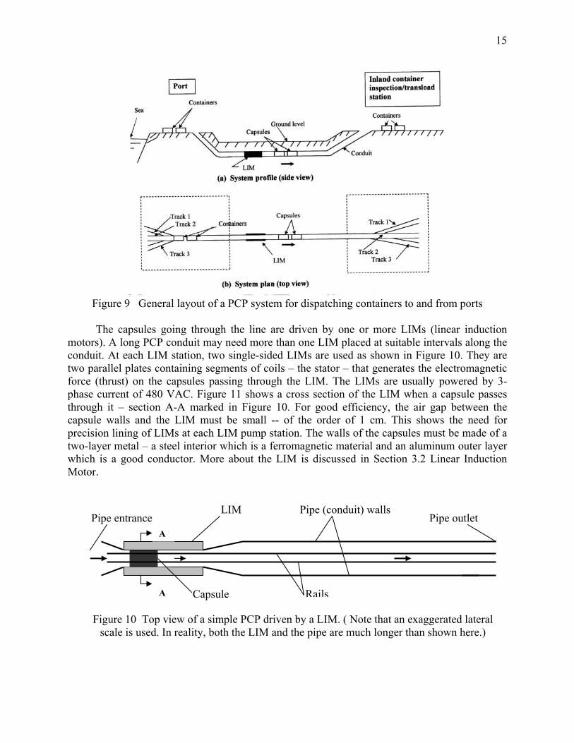
The capsules going through the line are driven by one or more LIMs (linear induction motors). A long PCP conduit may need more than one LIM placed at suitable intervals along the conduit. At each LIM station, two single-sided LIMs are used as shown in Figure 10. They are two parallel plates containing segments of coils – the stator – that generates the electromagnetic force (thrust) on the capsules passing through the LIM. The LIMs are usually powered by 3-phase current of 480 VAC. Figure 11 shows a cross section of the LIM when a capsule passes through it – section A-A marked in Figure 10. For good efficiency, the air gap between the capsule walls and the LIM must be small -- of the order of 1 cm. This shows the need for precision lining of LIMs at each LIM pump station. The walls of the capsules must be made of a two-layer metal – a steel interior which is a ferromagnetic material and an aluminum outer layer which is a good conductor. More about the LIM is discussed in Section 3.2 Linear Induction Motor.
LIM
Capsule
Pipe (conduit) walls
Figure 10 Top view of a simple PCP driven by a LIM. ( Note that an exaggerated lateral scale is used. In reality, both the LIM and the pipe are much longer than shown here.)
Pipe outlet Pipe entrance A
A Rails

16
Figure 11 Cross section of a capsule in a LIM (Sec. A-A of Figure 10)
Because New York City and adjacent New Jersey have several container ports scattered around a relatively small geographical area, it is possible to have a single PCP with multiple inlets and only a single outlet to serve these ports, as illustrated in Figure 12. Detailed route planning for the PCP and the selection of the location of the outlet terminal – the container inspection/transfer station – should be left for the Port Authority of New York and New Jersey to do.
Figure 12 General illustration of a container-dispatch PCP system for serving NY & NJ ports As will be shown in Sec.4.5, the above PCP system for dispatch containers to and from the ports of New York City contributes not only to port security and a drastic reduction of the number of trucks entering and leaving New York City, but also to the economic development of the City and reduced transportation costs for containers entering and leaving of the City.
Capsule
Wheel (steel) Rail
(steel)
Concrete floor
Drain pipe (horizontal) Drain (vertical)
LIM
Support
LIM
Support
Air gap
Support
ContainersPort B Port A Inspection/transfer
Twin lines
Port C
Port D
station (inland rural area)
Deep underground tunnel (round)
Shallow underground conduit (rectangular)

17
2.4 TRUCK-FERRY PCP SYSTEM The largest PCP system that can be used in New York City involves using large capsules rolling on rails in tunnels or underground conduits, with each capsule carrying an entire truck or tractor trailer. The trucks (including tractor trailers and vans) are piggybacked by the capsule, in much the same manner trucks and cars are piggybacked through the Euro Tunnel from England to France [19]. The only main differences are: the system proposed for use in New York City uses pneumatically driven PCP capsules instead of electric trains, the system is on land instead of undersea, and it is much shorter and simpler than the English Channel Tunnel. Due to these differences, the estimated cost for building the PCP system in NYC is only a fraction of the cost of the Euro Tunnel. Where is such a PCP system applicable to New York City? This project has determined that Hunts Point, a peninsula of Bronx, is the place that may benefit from such a PCP. This is explained briefly below. Hunts Point is the place in New York City where the City’s foods are processed, serving millions of people in the New York Metropolitan area. It has the nation’s largest produce processing center, and the nation’s largest meat processing center. A large fish market is also under construction there. Each day, over 3,000 trucks of various sizes enter Hunts Point from its north and proceed to its south, either to pick up the processed foods from or deliver the unprocessed foods to the food processing centers, which are located next to each other in the southeast corner of Hunts Point – along the Food Center Drive. The high-density truck traffic in Hunts Point has caused not only accidents but also severe air pollution. Studies by health officials have found that residents of Hunts Point suffer from the highest asthma rate in New York City, which is believed to be an indication of the health problem generated by trucks. Both the residents of Hunts Point and the New York City officials are very concerned about the truck-generated problems in Hunts Point, and have sought various solutions. One solution is to have a dedicated truck route to Food Center Drive. While that solution helps to reduce truck traffic through residential and business areas, it has little impact on air pollution in the area. Another solution – a current practice–is to ban idling trucks (i.e., prohibiting any parked trucks from leaving their engine running for more than three minutes). While this measure does help to reduce air pollution, the benefit is limited because trucks are still polluting air when they are moving, and besides, some trucks carrying refrigerated foods cannot stop their engines for long without affecting the foods that they carry. The implementation of various truck-stop electrification systems also helps to minimize the problem. However, according to the management of the Hunts Point meat market, at present only a small number of refrigerated trucks are properly equipped for hook-up to the electrical facility of the market. Plans have also been made to promote more use of railroads from and to the food processing centers. However, railroads can only provide limited relief because most of the unprocessed foods carried by trucks come from different places of the nation (e.g., Florida, the Midwest, etc.), and most of the processed foods carried by trucks and vans are destined to different parts of the New York Metropolitan area. Only a small percentage of foods can be shipped via railroads. It is believed that using a PCP to ferry trucks underground through a tunnel or underground conduit from north to south along the east coast of Hunts Point peninsula offers a potentially viable solution to Hunts Point’s truck problem. Two alternative routes for the truck-ferrying PCP have been investigated in this study for Hunts Points – AB and CD shown in Figure 13. Various aspects of the two routes have been considered, including geology (ground condition), relative buildup (urban development), intersection with existing underground utilities, construction difficulties, and accessibility to

18
freeway outlets. The study found that the east route, CD, is preferable. This route connects point D, the north end of the proposed PCP conduit, to two freeways (I-278 and I-895). It enables easy freeway access from and to three different directions. The total distance of the CD route, following a slightly curved path, is approximately 1.8 km (1.1 miles). Some curvatures are included to avoid crossing existing structures, and minimizing construction difficulty. The south end of the route, point C, reaches the southeast end of the produce market (officially called the “Hunts Point Terminal Market”). Trucks ferried to point C via the PCP can reach the various buildings of the Produce Market within 500 ft, and can reach the meat market via the Food Center Drive within 1,000 ft. Once the trucks are ferried from point D to C, they need to drive only for a short distance along the Food Center Drive. Also, the route traverses the least built-up area of Hunts Point, enabling the use of open-cut for construction.
Figure 13. Proposed alternative PCP routes (AB and CD) investigated for ferrying trucks across Hunts Point. (Note that the east route, CD, was found to be the preferred route.)

19
As with the other PCP systems discussed here, the truck-ferry PCP in Hunts Point will use a dual conduit (twin pipes), so that capsules can move simultaneously in opposite directions. Depending on construction costs, this PCP system in Hunts Point may use either rectangular conduits of 10 ft width and 15 ft height, or circular tunnels of 18 ft diameter. The rectangular shape is more cost effective if the open-cut method is used for constructing the conduits, whereas the circular shape is more cost effective if the conduits (tunnels) are bored through bedrock using tunnel boring machines (TBMs). A preliminary investigation of the selected route (CD) indicated that it is possible to use the open-cut method to construct the truck-ferrying PCP along this route without affecting existing structures. Whenever any existing water or sewer pipes are encountered, careful digging around these pipes will avoid damaging them. Because the top of the underground twin conduits of the PCP can be placed 10 to 20 ft below the ground level, they can cross existing pipes from underneath without problem. An anticipated problem is groundwater and water infiltrating from the Bronx River, which will make construction more difficult and costly than usual. However, by using modern construction methods, the water problem can be handled. The carriers of the trucks are flatbed capsules of 9 ft width. Three different capsule lengths will be used to carry trucks or vans of different lengths: 60, 40 and 20 ft. Each 60-ft capsule can ferry a 53-ft-length tractor trailer; each 40 ft capsule can ferry a 35-ft truck; and each 20-ft capsule can furry a van or pickup truck. Figure 14 shows the general layout of the proposed PCP system. Note that due to the relatively small number of trucks that need to be transported by this system – 1,750 trucks per day through each tube or a total of 3,500 trucks per day for two directions – a blower instead of LIM can be used in this case. As analyzed in Appendix B.2, with a blower of 40 kw, one capsule can be propelled through each conduit of 1.7 km in every 50 seconds, at the top speed of 30 mph (48 km/h), and it will take less than 3 minutes for any capsule to move through the conduit. The operation of the system is described next.
Figure 14. General layout of a truck-ferry PCP system designed for use in Hunts Point.

20
When a truck carrying foods enters the inlet station of the PCP, the driver drives the truck onto a parked capsule of the appropriate size (length) at the terminal. Different lengths of empty capsules are parked in different lanes. The driver drives the truck onto the flatbed capsule, turns on the parking brake, closes the truck doors and windows, turns off ignition, and remains seated with the safety belt on. This process takes less than 60 seconds. Then, a worker at the terminal closes the rear door of the capsule, and pushes a button to launch the capsule. The capsule is launched by the thrust of a pneumatic ram of appropriate strength, or another suitable means. Due to the sloped entrance of the conduit as shown in Figure 14 (a), gravity accelerates the capsule as it enters the conduit. As soon as the capsule has passed the open gate, the gate will close automatically, and the blower will be turned on automatically, blowing the capsule with its load (the truck) through the 1.7 km distance to the conduit outlet, which is near the food center. The whole trip will take less than 3 minutes – see calculation in Appendix B.2. During transit, the capsule motion is entirely automatic, and the truck driver needs to do nothing except to enjoy a short ride. As has been demonstrated by the Euro Tunnel [19], such rides are convenient, comfortable and safe. As soon as the capsule approaches the Food Center (point C in Figure 13), it will decelerate automatically due to the rising slope of the exit conduit – see Figure 14 (a) – and will come to a stop outside the conduit in the terminal. Then, a worker at the terminal will open the front door of the capsule to let the truck out. The trucker starts the ignition, and drives the truck to the specific store in the Food Center, as he (she) currently does without using the PCP system. The driving distance within the Food Center will be short, not more than a few hundred yards. After unloading its cargo, the truck can leave Hunts Point with or without carrying foods, by using the same PCP system in the reverse direction. In passing, it should be mentioned that each capsule will have its own brakes powered by compressed air – the same as for conventional railroad train brakes. The brakes can be activated either manually by the attendants at the PCP terminals, or automatically through remote control using an RFI (Radio Frequency Identification) system. This truck-ferrying PCP in Hunts Point is expected to bring the following benefits to Hunts Point, Bronx and New York City:
• Avoiding the need for trucks to cross the business areas and the residential areas of Hunts Point in order to enter and leave the Food Center. It will drastically cut down the number of trucks running on the streets of Hunts Point.
• It will drastically cut down the air pollution problem caused by trucks in Hunts Point. This will benefit not only Hunts Point but also Bronx and the entire New York City.
• It will facilitate food delivery, especially during inclement weather such as when the streets are covered by ice and snow.
• The many acres of land above the underground PCP system and along the Bronx River can be turned into a riverfront park. It will provide a much needed outdoor recreational facility to the residents of Hunts Point and Bronx.
• The uniqueness of the truck-ferry system will bring tourists to Hunts Point, thereby helping the economic development of the Hunts Point. This was found to be true for the Euro Tunnel, which attracts tourists.
As will be shown in Sec.4.6, the truck-ferrying PCP in Hunts Point is the only one of the six analyzed potential applications of PCP in New York City that cannot be justified on economic grounds alone.

21
2.5 OTHER POTENTIAL APPLICATIONS (a) Solid Waste Transport
According to published sources [20-23], the New York City now generates approximately 12,000 tons per day of residential and institutional solid waste, and 27,000 tons per day of commercial wastes. Prior to 2001, all the residential and institutional solid wastes were collected by the City’s Department of Sanitation (DSNY) and transported to a single landfill in the City – the Fresh Kills landfill on the Staten Island, and the commercial wastes were collected by private carters and transported to approximately a hundred transfer stations scattered around the city, mostly in Bronx, Brooklyn and Queens, to be processed and then exported – trucked to landfills in New Jersey and other states. However, since the closure of the Fresh Kills landfill by the City in 2001, all the residential and institutional solid wastes collected by the DSNY are now transported by garbage trucks to eight marine transfer stations with at least one in each borough, and one land-based transfer station on Staten Island. At the transfer stations, the wastes are compacted and fit into 20-ft-long containers. The waste containers at the marine transfer stations are carried by river barges that transport the containers to oceangoing ships and then to trucks for export to New Jersey or other states. According to [20], since the closure of the Fresh Kills landfill, the cost of transferring, transporting and disposing the 12,000 tons per day of garbage in New York City has been skyrocketing: $578 million in 1997, $996 million in 2001, and expected to reach $1 billion per year in 2003. In addition to the direct cost paid for the services, the indirect social costs have been high, as quoted below [20]: “… 425,000 extra trips each year by diesel exhaust-spewing garbage trucks, substantially raising the pollution levels along the routes and around the transfer stations. ……Managing such huge volume of waste also causes substantial regional and global environmental problems associated with the extraction, manufacture, and transport of excess goods and packaging, impacting on natural resources, energy and materials use, and on global warming.” A number of measures are being taken by New York City government, industries and residents, in mitigating the aforementioned problems. Such measures include waste prevention (i.e., encouraging measures and habits that reduces waste generation), and measures to recycle waste materials. However, even with the best waste prevention and recycle programs, there will still be a large amount of solid wastes generated in the highly populated New York City that must be exported to landfills and/or waste recycling stations in less populated neighboring areas in New York and other states such as New Jersey. As will be shown next, the same PCP system used successfully in Japan for limestone transport can be used to transport the New York City solid wastes to such sites. Since 1980, Japan has successfully used a PCP to transport more than 2 million tons of limestone per year from a mine to a large cement plant in Kuzuu, Japan [3]. This PCP was built in 1980 to replace an existing railroad, which had been causing accidents and air pollution problems. The PCP system uses a 40-inch-diameter steel pipe buried underground, using the decommissioned railroad right-of-way. Figure 15 shows the inlet station of this PCP. The pipeline has compiled an impressive record, and is still operating today and will for many more years to come. Not only has this PCP prevented accidents and air pollution that would have been caused by the rail, it also has saved money for the Sumitomo company and has pleased area residents. The system also was found to be highly reliable, achieving over 95% of availability.

22
(a) Bird-eye view of the Inlet station (b) Close-up view of materials loading into capsules Figure 15 The inlet loading system of PCP transport of limestone in Kuzzu, Japan; 40-in-diameter steel pipe is used in this project. (Courtsey of the Sumitomo Metal Industries, Ltd.) The same system used successfully in Kuzuu for transporting limestone, with minor modifications, can be used to transport the solid waste of New York City. The system as it is, using blowers instead of linear induction motors (LIMs), can be expanded to transport up to 5 million tons of materials a year. In a 24-hour(3-shift)-a-day operation with 95% availability, the amount of compacted solid wastes that this 40-inch-diameter pipeline can transport in a day using the current technology (blowers) is approximately 13,000 tons, which is about the same as the total solid wastes collected by the DSNY. With system improvements such as using LIMs instead of blowers and using parallel loading and unloading lines, the same 40-inch-diameter pneumatic capsule pipeline (PCP) can be used not only to transport the entire amount of the solid wastes handled by the DSNY but also all of the commercial solid wastes handled by private companies. To minimize the system costs and to minimize changes to the current transfer stations, it is proposed that the PCP system for transporting the wastes collected and compacted at each of the current nine transfer stations has nine inlet stations – one at each inlet station—and has a pipe branch connected to each transfer station. The nine branches will intersect downstream and merge into a common line to take all the wastes to a common large landfill in a remote location to be purchased by the City of New York, or to more than one processing/disposable sites along the route of the pipeline. The network of pipes will be similar to that shown in Figure 12 for dispatching containers from ports, except that the pipe is much smaller (40 inches in diameter), and the system has nine intake stations and inlet lines. Most of the pipe near the inlets (i.e. near the marine waste transfer stations) will be laid a few feet under the river beds, which can be done easily with 40-inch steel pipes using modern offshore pipeline construction technology. The land portion of the pipe in rural areas will be buried 3 to 5 ft underground using the open-cut method which is the most economical and the most common way of construction of long-distance pipelines. On land when crossing rivers, roads, buildings and other structures, the modern technologies of directional drilling and pipe-jacking will be used to construct the pipe – see Sec.3.5 (a) Tunneling for details. The ultimate disposal site is a large landfill or waste recycling plant at a relatively remote area where the wastes are first processed to recover and recycle some of the materials, and the non-recyclable part is buried in the landfill. Having such a system for transporting and disposing the solid wastes will benefit New York City in the following ways:

23
• It will eliminate the need for using barges and ships to move solid wastes from transfer stations to ports and then to haul the wastes by trucks and trains to landfills. Consequently, all the accidents, pollution and traffic problems caused by barges, ships, trucks and trains used for this purpose are eliminated.
• Since barges, ships, trucks and trains all use diesel fuel while PCP uses electricity, the latter is much cleaner and use domestic-generated energy rather than foreign oil. Thus, the PCP system reduces the City’s and the nation’s dependence on foreign oil.
• The PCP system is highly automated, reliable, and insensitive to inclement whether. It operates continuously 24-hours a day and 365 days a year except for an anticipated less than 5% downtime. Due to this, it does not require nearly as large a storage and processing area as that required currently at each transfer station. This means savings of space at each transfer station which can be converted to other more valuable uses such as commercial or industrial use. Also, the pile of solid waste stored at each transfer station will be significantly reduced, resulting in less foul air and reduced odor and esthetic problems at or near each transfer station.
• Because recycling of waste materials can be done at a lower cost at the remote location of the ultimate disposal site (near or at the landfill) than at the transfer stations in New York City, more waste recovery will be possible than at the current sites.
• The PCP transport system will result in substantial cost savings for the City – see Sec.4.2 for cost estimates.
Notwithstanding the foregoing benefits, switching from the current to the aforementioned future PCP system will not change the way solid wastes are collected in New York City from the source (i.e., each individual homes, buildings, or parks that generate wastes) , or the way they are transported from the source to the waste transfer stations. The City will have to wait until the pallet-tube PCP system discussed in Sec.2.2 is built before solid waste can be transported by PCP from the source to each transfer station. The same pallet-tube PCP system for ordinary cargoes can be used also for transporting solid wastes contained in plastic bags. The bags will be loaded into special capsules that have tighter seals than ordinary capsules have, so that the foul odor of the waste materials will not permeate into the pipe outside the capsules.
(b) Mail and Parcel Transport The U. S. Post Office Department, the ancestor of the current U. S. Postal Service, was the pioneer in the U. S. to use “pneumatic tubes”—the archaic form of the current pneumatic capsule pipelines (PCPs). According to an interesting and detailed review article on pneumatic mail tubes written by Postal Inspector Robert Cohen in 1999 [24], as early as 1892, the U.S. Congress authorized $10,000 for an investigation of the “rapid dispatch of mail by means of pneumatic tube.” Immediate thereafter, Postmaster General Wanamaker solicited bids for contractors to demonstrate the system; the contract was awarded to the Pneumatic Transit Company of New Jersey. The first test was conducted in Philadelphia in 1893 between the Philadelphia General Post Office and the East Chester Street Post Office, over a distance of 0.58 miles. The test was successful and tube service officially began in Philadelphia; soon it spread to four other cities – New York, Boston, Chicago and St. Louis. The New York City’s system of mail tubes began in 1897, and continued to expand over the years until 1953 when it was discontinued – having well served the city for over a half century. At its peak, the New York City system had about 56 miles of tubes, made of 8-inch-

24
diameter cast iron pipes. The system connected 23 post offices in Manhattan to two offices in Brooklyn and one in Bronx. The connection to Brooklyn was via the famous Brooklyn Bridge. The entire tube mail system in New York City transported approximately 200,000 letters an hour, constituting approximately 55% of the total mail in New York City in 1953. Figures 16 and 17 are two photographs of the historic system.
Capsules (cylinders)
Figure 16 Prior to 1953, New York City postal workers, known then as “racketeers”, are shown feeding capsules (then called “cylinders” or “torpedoes”) containing letters into pneumatic tubes [24].
Receiver (Receiving canvas table) Capsule Tube Outlet Tube Inlet
other U
•
Figure 17 Transmitters and receivers of capsules (“cylinders”) in a post office room in New York City [24].
The main reasons for discontinuing the use of pneumatic mail tubes in New York and .S. cities in the 1950s are the following: The system, built around the turn of the century (1895-1905), had become increasingly old by 1950 and in need of repair after half a century of usage. With the pipes being underground (3 to 5 ft below the street level) and in buildings, it was costly to replace them with a modern system.

25
• The tubes, 8 inches in diameter, were too small. They could only transport regular size letters and small parcels. The 200,000-letters-an-hour capacity, which was adequate for New York City in 1900, had become inadequate by 1950. The sizes of letters and parcels had also grown significantly in the 50 years, making the system obsolete by 1950.
• The old system used obsolete technologies, making the system unreliable and labor intensive. For instance, the capsules used were plain cylinders without wheels, which often got stuck in the tubes (pipes) and clogged the pipes. To minimize the clogging problem, the entire interior of the pipe had to be lubricated with oil, which was not only costly but made the capsule surface dirty (oily) and handling more difficult. Also, some letters got contaminated by oil during loading/unloading.
Due to the above reasons, and due to the fact that by 1955 trucks had become popular and could move around cities easily, including New York City, without running into or causing traffic jams, it made perfect sense for the Post Office Department to discontinue the use of the obsolete mail tubes in New York and other cities, and to rely exclusively on trucks for delivering mail from post offices to rail stations or airports. History has shown that most societies are receptive to beneficial use of new technologies. Whenever a new technology is developed and proved to be beneficial to the society, the new technology will be used sooner or later. This is expected to be the case with pneumatic capsule pipeline (PCP). The modern technology of PCP, using wheeled capsules and large diameter pipes, enables the transport of many cargoes hitherto not transportable by pipelines. In the writer’s opinion, it is only a matter of time before the U. S. Postal Service will again be attracted to pipeline transportation of mail and parcels, using the modern PCP technology, and using large diameter pipelines. The following is an envisaged potential future use of PCPs in New York City for transporting mail and parcels: Sorted mail and parcels destined for any East Coast city between New York and Washington D.C. are first transported by trucks over a short distance to one or more PCP inlets located either in the City or at its outskirts. Then the mail and parcels will be loaded in the same type of capsules that are currently being used in Japan for limestone transport and the type recommended for use in New York City for transporting solid waste, except that the mail-parcel pipeline will be a separate system from the trash pipeline of New York City. As in the trash pipeline case, the mail-parcel PCP will use multiple inlets, and 40-inch-diameter steel pipe. Unlike the proposed trash pipeline which is less than 100 miles in length, the mail-parcel PCP will be over 200 miles long, spanning all the way from New York City to Washington D.C. The mail-parcel pipeline is also different in that it will have many intermediate stations with inlets and outlets, with at least one of such stations to serve each major city along the route. Thus, it constitutes a complex transportation system similar to an interstate highway system that will serve all the states and cities along the pipeline route from New York to Washington D.C. To minimize construction difficulties and costs, the pipeline route should use the right-of-way of an existing interstate highway, such as I-95. It is relatively easy to accommodate two 40-inch steel pipes – one on each side of the highway—along the existing easement of an interstate highway. Because the pipes will be buried 3 to 5 ft underground and will use low-pressure air, they will not impede traffic, nor cause safety problems. However, approval from all the states along the route (New York, New Jersey, Pennsylvania, Delaware and Maryland) and the Federal Highway Administration, and an act of the Congress will be needed before this pipeline can be built along any interstate highway. It will be a major undertaking that will take years to get approvals for the

26
right-of-way before financing and construction can take place. Still, due to its huge potential benefits to New York City and New York State, the City and the State may want to consider spearheading the project. With the use of linear induction motors (LIMs) instead of blowers, the system has sufficient capacity to transport all the mail and parcels of not only the Postal Service but also the Federal Express, United Parcel Service, and other carriers, along this route. Therefore, it only makes sense for the pipeline to be used and financed not only by the Postal Service but also other private carriers. The system will benefit New York and other states along the route or corridor in the following ways:
• It will significantly reduce the number of trucks along I-95 between New York City and Washington D.C. – one of the busiest highways on the East Coast. Consequently, it will significantly reduce traffic congestion, accidents, air pollution, and road and bridge damages along this important highway caused by trucks.
• It will speed up mail and parcel delivery along this busy corridor. For the longest distance along this corridor (215 miles between New York City and Washington, D.C.), the transportation time will be about 6 hours for capsules traveling at 35 mph, and it can be faster if necessary. Because the system operates continuously – 24-hours a day and 365-days a year – all the mail and parcels going through this pipeline can be easily delivered within 24 hours, to meet the requirement of express mail services.
• The system being underground is unaffected by inclement weather. Theft of cargo during transit is also nearly impossible.
• If fully utilized by various carriers, the transportation cost in $/TM (dollars per ton per mile of distance) will be much less than by existing transportation means – see cost analysis in Sec.4.3.
• The system uses electricity instead of diesel; therefore, it reduces U.S. reliance on foreign oil. Besides, the energy efficiency of PCPs, in terms of Btu/TM (Btu of energy used per ton-mile of cargo transported), is significantly better than that of trucks [25]. Thus, using PCPs instead of trucks conserves energy.
• As will be seen in Sec.4.3, this PCP is highly cost effective. Mail and parcels can be transported by this pipeline at a fraction of the cost of that transported by trucks and airplanes.
(c) Use of Existing Right-of-Ways An attempt was made in the beginning of this study to identify the right-of-ways of existing tunnels (including subway tunnels, highway tunnels, rail tunnels and water tunnels) and other structures in New York City that might be utilized for constructing PCPs in the City. Finding such existing right-of-ways that can be utilized for constructing PCPs would greatly reduce the cost and facilitate the use of PCPs in New York City. However, soon it was discovered that it was difficult if not impossible to identify such right-of-ways. The difficulty arises from three factors. First, most existing tunnels have little unutilized or underutilized space for a PCP of significant size, such as 3-ft diameter or larger. Secondly, there is an institutional barrier. Agencies in charge of tunnels contacted by this project were reluctant to provide information on underutilized tunnels for possible use by PCPs. Because freight transport is not a part of their official duties, they consider possible use of PCPs in their tunnels for freight transport as an intrusion and threat rather than blessing. Third, even though there are many reports on abandoned tunnels in New York City, such as those discussed in [11, 26, 27], the

27
abandoned tunnels are either too short, too difficult to find key information about, or have already been converted to other usages. Due to these, preliminary investigation of this study was unable to identify any existing underground tunnel in New York City that are suitable for constructing a PCP of 3-ft diameter or larger. Even though there are numerous abandoned pipes in New York City (old water pipes, old sewer pipes and old pneumatic mail tubes), they are undocumented and mostly too small in diameter for any significant reuse as a PCP. For these reasons, this project soon discovered that the quest for using existing tunnels for PCPs in New York City was unproductive, and quickly focused on new tunnels and new lines that are more feasible and economically justifiable. In spite of the focus of this study on constructing new tunnels and new pipelines for PCPs, the study has not exhausted the possibility of the existence of abandoned or underutilized tunnels that can be used. Nor has it examined the feasibility of using or sharing the right-of-way of some existing aboveground structures, such as railroads, highways, or the AirTrain to the John F. Kennedy Airport, for freight transport using PCP. The scope of the study and the project budget prevented such investigations. Therefore, it is quite possible and even likely that future investigators will find it feasible to use the right-of-way of some existing infrastructures in New York City for freight transport using PCP, to the benefit of the City.
28
Section 3 TECHNOLOGY ASSESSMENT
In this section, important issues pertaining to the technical feasibility of using PCPs in New York City for the potential applications discussed in the previous section are assessed and addressed. The section also provides key technical information needed for future planning, design and construction of PCPs in New York City and elsewhere in the nation and the world. 3.1 Pneumatic Capsule Pipeline (PCP)
(a) Difference between PCP and Tube Transport Pneumatic capsule pipeline (PCP) is the modern and large version of the “tube transport” such as used for mail transport in New York and four other U.S. cities prior to 1953 [24, 28, 29], and such as those still in use in the U.S. for transporting light-weight articles at drive-in banks, hospitals, airport terminals and large factories and office complexes [16]. Essentially, PCP differs from tube transport in that it uses large pipes – usually 3-ft-diameter or larger pipes, and the capsules are large and supported by wheels to reduce contact friction – see Figures 1-4. In contrast to the tube transport system which uses non-wheeled capsules each carrying only a few pounds of cargoes, the PCP system uses large wheeled capsules each carrying more than one ton of cargo. For instance, each of the capsules used in Japan for transporting limestone in a 1m diameter pipe can carry approximately 2 tons of limestone. Also, PCPs are highly automated and use a centralized computer system, SCADA (Supervisory Control and Data Acquisition), for control and operation of the pipeline. It is a far cry from the primitive mail tube transport systems used by the Post Office Department over half a century ago [24]. This study sponsored by NYSERDA is focused on using PCPs instead of tube transport systems in New York City. (b) Readiness of the PCP Technology for Use in New York City Due to the well documented successful commercial use of the blower-based PCP systems in Japan for various purposes, such as tunnel construction [4], highway construction [4], transport of minerals [3], and transport and disposal of solid wastes [7], and due to less documented yet successful use of the blower-based PCPs in the former Soviet Union for rock transport [30], the blower-based PCP is an existing technology that requires no further research or demonstration before it can be used successfully anywhere in the world, including New York City. It can be used readily for those potential applications in New York City that use blowers to drive the systems. They include the PCP for tunnel construction, the PCP for solid waste transport and disposal, and the PCP for ferrying trucks in Hunts Point. On the other hand, the other three potential applications of PCP in New York City, including the system for pallet-tube freight transport, the system for dispatching containers, and the system for mail transport, all require the use of a linear induction motor (LIM) pump which has not yet be demonstrated beyond the laboratory scale for use in PCP. Therefore, it may be prudent to demonstrate and test either a prototype or a large-scale model of a PCP-LIM before using it in those three aforementioned applications, or as part of the pre-engineering of the commercial project. Such a demonstration/test will enable the designer to design an efficient LIM-based PCP system, and to minimize design mistakes and resultant system modifications following the first commercial use of such a system. However, even for the systems that use LIM, further R & D is not necessary before first commercial use. Societies cannot afford to wait for the perfection of any beneficial major technology before the technology is used. Finally, while no further research is necessary

29
before the PCP technology can be used successfully in New York City, it does not mean that no research is needed to further improve the PCP technology. As it is the case with other major technologies such as trucks and airplanes, even after a century of commercial use there is still room for R & D to further improve the technology. (c) Wheels of PCP Capsules All the existing PCP systems use wheeled capsules. For capsules in rectangular pipes – see Figure 1 (b) – the capsule wheels that support the weight of the capsule are mounted on the bottom of the capsule, in a manner similar to ordinary vehicles. Side wheels (guide wheels) are also used to keep capsules stable during motion and to reduce contact friction between the capsules and the pipe walls. In contrast, for capsules in a round pipe – see Figure 1 (a) – the wheels are very different. They consist of two gimbaled wheel assemblies, one mounted on each end of a capsule, pivoted at the center axis of the capsule. Such wheel assemblies keep the capsule in a stable position in the pipe to prevent spill of cargoes. While the wheel assemblies are free to rotate around the inner circumference of the pipe, the capsule with its center of gravity being below the pivoting point always remains stable. All the wheels in the capsule pipeline systems in Japan use tires made of a hard synthetic rubber. Such tires have the following advantages: softening the impacts between the wheels and the pipe, reducing the pipe wear, and reducing the noise generated by capsules moving through the pipe. On the other hand, the rubber-tire wheels have the following disadvantages as compared to simple steel wheels without rubber tires, such as those used by railroad trains: greater wheel friction which waste energy, and greater wear of wheels (tires) which increases maintenance need and costs. Considering the aforementioned advantages/disadvantages, different types of wheels will be needed in different potential applications of PCP to New York City, as follows: (1) Tunnel construction PCP -- For the tunnel construction PCP system, the same bottom wheels using the same rubber tires as used in Japan for tunnel construction (see Figure 3) will be a good choice. This is so especially if the rectangular pipe of the PCP is made of concrete, as it was the case in Japan. Steel wheels cannot run on a concrete surface without causing severe wear to the concrete. (2) Solid waste PCP -- For the 50- to 100-mile long PCP required for transporting New York City solid wastes to an out-of-state disposal site, great energy savings can be accomplished by using steel wheels. The steel wheels will also reduce wear of the wheels, resulting in less maintenance cost than using rubber-tire wheels. The disadvantages of steel wheels are more noise and wear of the pipe. However, the noise will not be a problem because the pipeline is underground. Only at the two terminals will the noise be heard, and they will be within the 85 decibel required by OSHA for workplaces, and well below those heard at a train station when a train arrives or leaves. The wear to the pipe will also be minimum because the solid waste is not as heavy as minerals, and because the wear will be uniformly distributed over the lower one-third of the pipe circumference, due to the rotation of the gimbaled wheel assembly inside the pipe. Use of a steel (for wheels) containing less carbon than that used in the steel for the pipe will also reduce pipe wear due to the reduced hardness of the wheels. (3) Other larger PCP systems – For all the other potential applications that require the use of larger diameter pipes, including the pallet-tube PCP system, the container dispatch PCP system, and the truck-ferry PCP in the Hunts Point, the same types of steel wheels and steel rails used in ordinary railroads should be used. They have the following advantages:

30
• By using steel wheels on steel rails, the wheel friction coefficient (i.e., the rolling friction coefficient) can be reduced to about 0.002, which is five times smaller than that using rubber tires. This results in great saving of energy.
• Rails guide the motion of capsules, making it easy for capsules to enter a branch through railroad switches. The locations of the capsules in the terminal can also easily by controlled by the rails, thereby facilitating loading and unloading of capsules.
• The need for maintenance of steel wheels is much less than for rubber tires.
Details about using rails in PCP conduits to enhance the capability of PCP freight transport are currently being studied in a project sponsored by the U.S. Department of Energy [10]. (d) Capsule Trains The operation of PCPs is usually facilitated by tying individual capsules together to form trains, in the same way railroad trains are formed. Usually, each capsule train contains only three to five capsules. Longer trains can also be formed but would require longer stations (which take up more space), less frequent launching and arrival of trains, and longer time for loading and unloading each train. Figure 18 shows a capsule train with bottom wheels in a rectangular PCP containing three capsules for tunnel construction. For simplicity, the wheels were drawn on the bottom of the capsule between the two end plates. In reality, most capsules are designed to locate the wheels on the two ends of the capsules outside the end plates – see Figure 3.
Figure 18 Schematic of a capsule train of three capsules in a rectangular PCP. (e) Key Equations for System Design Contemporary PCP systems driven by blowers use capsules that contain two end plates (also called “end disks” or “seal plates”), one on each end of a capsule as shown in Figure 18. The end plates reduce the air leaking around the capsule, increase the drag force on the capsule, and make energy transfer between the air flow and the capsule more efficient. Based on fluid mechanics, the drag force on a capsule with end disks can be calculated from
2
)( 2c
DdDVV
CAF−
=ρ ………………………….. (3-1)

31
where FD is the drag force, Ad is the area of each end disk, CD is the drag coefficient, ρ is the density of the air in the pipe at the capsule location, V is the mean velocity of the air in the pipe, and Vc is the capsule velocity. The drag coefficient CD for any capsule with two end plates can be calculated from the following equation given by Kosugi [31]:
22
4
)1(4
d
dD k
kC
−= ……………………………. (3-2)
where kd is the ratio of the square-root of the disk area Ad to the square-root of the pipe inner cross-sectional area A, namely, kd=(Ad/A)1/2. Note that Eq. 3-2 is for any capsule having two end disks. For a capsule that has only one end disk, the factor 4 in the equation should be reduced to 2. For capsules without end disks, a totally different and more complicated approach, described in the final report of a U.S. Department of Energy project [10], should be used to determine CD. Note that PCP systems that use LIM (linear induction motors) do not use capsules that have end plates. The end plates must not be used for they create a large air gap and poor efficiency of the LIM. Once the drag coefficient CD is determined for the capsule and once the capsule velocity Vc is specified for the PCP system, the airflow velocity V in the pipe under steady-state operation can be calculated from the following equation:
ρ
η
dD
cc AC
WVV
2+= ………………………………… (3-3)
where η is the rolling friction coefficient of the wheels used by the capsule, which is approximately 0.01 for rubber-tire wheels, and 0.002 for steel wheels rolling on a steel surface; and Wc is the capsule weight. For capsules without end disks, Eq.3-3 still holds, but the area Ad should be changed to Ac, the cross-sectional area of the capsule. Once the velocity is calculated from the above equation, the pressure drop along the entire length of the PCP under steady state operation can be calculated from:
2
)( 2VDNLL
fAWN
ppp ccfc
ρη −+=∆+∆=∆ ………………… (3-4)
where ∆pc is the pressure drop due to the capsules in the pipe; ∆pf is the pressure drop due to the motion of the air through the pipe in the capsule-free space; f is the Darcy-Weisbach friction coefficient that can be found from the Moody diagram in fluid mechanics; N is the number of capsules in the pipeline; L is the total length of the pipeline; Lc is the length of each capsule; and D is the pipe diameter. For non-circular pipe, use 4RH where RH is the hydraulic radius, in lieu of D. The number N can be calculated from
cTV
LN = …………………………………….. (3-5)
where T is the time interval between successive injections of capsules into the PCP. Once the pressure drop ∆p is known, the power consumed by the flow of air and capsules through the pipe is

32
pVApQP ∆=∆= …………………………………… (3-6) where Q is the volumetric flow rate (discharge) of the air. Assuming the blower or LIM pump efficiency to be E, where E is a number smaller than 1.0, the power input to the blower or LIM pump is pEVApEQPin ∆=∆= ………………………………. (3-7) For large blowers, E is in the neighborhood of 90%, and for large LIM pumps E is approximately 70%. (f) Brakes for Capsules The capsules used in contemporary systems such as those in Japan do not have brakes. However, for the large PCP systems considered here for potential use in New York City (i.e., for the large systems that use steel wheels and rails), it is desirable to have a braking system for each individual capsule. The braking system recommended for use here is basically the same as used on ordinary railroad trains, which use compressed air as the energy source to activate brakes. In ordinary railroad trains, each car contains its own compressed air tank which is connected to the locomotive for central control by the conductor (engineer) of the train seated in the locomotive. For PCP each capsule will carry its own compressed air tank as in the case of ordinary railroad trains. However, the air tanks will not be connected to the locomotive because PCPs have no locomotives and no human driver or conductor. Therefore, activation of the brakes of each capsule must be done externally through automatic remote control and an onboard PLC (Programmable Logic Controller). Whenever there is a need for the capsule brakes to be applied, such as when a capsule approaches a terminal, a remote signal will be sent to the capsule to activate the brake. The capsule brakes will also be applied automatically whenever capsules have come to a complete stop. This will prevent any accidental movement of the capsules after they have come to a stop, until the capsules in a train are ready to move again and a remote signal has been sent to release the brakes of the capsules in this train. (g) Drive Types All conventional PCPs use blowers to drive the system. However, in many circumstances, it is better to use linear induction motors (LIMs) instead of blowers for the following reasons:
• Blowers are intrusive and do not allow passage of capsules through them. In contrast, LIMs are non-intrusive, allowing the passage of both air and capsules through them unimpeded. Therefore, long PCP systems that require booster pumps cannot use blowers but can use LIMs. This greatly facilitates the use of PCP for long distances.
• The LIM-based PCPs can have much larger (3 to 5 times larger) throughput than possible with the blower-driven PCP systems. This reduces unit freight transport cost in terms of $/TM (dollars per ton of cargo transported per mile of distance). However, this economic advantage cannot be realized until and unless the system demand (i.e., the throughput of cargoes required) is very high.
• The LIM-based PCPs can have multiple inlets and/or multiple outlets. It is necessary for sophisticated PCP systems that have multiple inlets and/or multiple outlets.
• To be efficient, blower-based PCP systems must use seal plates (end disks) on each capsule. In contrast, the efficiency of LIM-based PCP is insensitive to the use of seal

33
plates. Since seal plates are difficult to use in any PCP that has non-uniform pipe geometries -- such as a round pipe constructed by tunneling followed by a rectangular conduit constructed as a result of open cuts – use of LIMs is more suited in such special cases.
Due to the foregoing reasons, both the blower type and the LIM type PCPs are applicable to New York City for different applications – the blower type for tunnel construction, solid waste transport, and ferrying trucks in Hunts Point, and the LIM type for the pallet transport system, the container dispatch system, and the mail transport system.
(h) Operation of PCP Systems The operation of various blower-based PCP systems is basically the same. A loaded capsule train consisting of 3 to 5 capsules is injected into the pipe one at a time. The motion of the capsule train is initiated by an external thrust force generated at the inlet station. The thrust can be provided either by a pneumatic cylinder or a linear motor. Shortly after the capsule train has started to move, the train arrives at a man-made decline as shown in Figure 14 (a) which accelerates the train until it reaches the bottom of the pipe inlet. Then a gate near the inlet is closed behind the capsule, and a fan is started which blows the air through the pipe which in turn drags the train along. A short time (say, 40 seconds) later, the inlet gate is opened and another capsule train is fed into the pipe in the same manner as the first train. This continues for some time until the first capsule train in the pipe exits the pipe. The upward slope or incline at the pipe exit causes the capsule train to slowdown by gravity as soon as the train enters the outlet station. Then the brakes are triggered which bring the train to a quick stop. Control of train motion, from start to stop, is automatic. Sensors will be used to control the motion of the gate at the inlet, to turn the blowers on and off, and to activate the brakes as soon as the train has entered the outlet station. Launching of any loaded capsule train will be done manually by pushing a button, as soon as the train is ready to go. As soon as any capsule train has been unloaded of its cargoes, it can reenter the pipe in the opposite direction in much the same manner as during the cargo delivery trip. The operation of the entire system will require a SCADA and one or more than one PLC. Each capsule will carry a RFID (Radio Frequency Identification) tag, the same used at highway toll booths for keeping track of and controlling the flow of automobiles. Whenever the PCP system is shutdown, both the inlet gate and a similar outlet gate will be closed, preventing unwelcome would-be intruders from entering the pipe. The operation of a LIM-based PCP will be slightly different from that discussed above for a blower based PCP. First of all, the inlet and outlet gates will be always open when the system is in operation. Secondly, the LIM will be controlled automatically by a PLC in a manner to be discussed in Sec.3.2, Linear Induction Motor. Launching of capsule trains into the pipe at the PCP inlet station, and exiting of such trains from the pipe into the outlet station, are both identical to that for the blower-based PCPs. (i) Maintenance of PCP Systems For any PCP system, maintenance of the pipe itself is easy and infrequent, similar to those of maintaining ordinary pipelines (gas and oil pipelines) for systems without rails, and similar to those of maintaining railroads for those PCPs containing rails. More frequent maintenance is expected for the wheels of the capsules, and for the blowers of the blower-based PCP systems. The wheels must be examined and lubricated after every 10,000 miles of use, and the blower
34
should be examined and greased after every 6 months. The LIM, being a stationary device, is expected to need little maintenance. The only part of the LIM that needs frequent inspection is the inner surface of the LIM and the gap between the LIM and the capsule – making sure that the LIM’s internal surface is not damaged, and the air gap is properly maintained. Should the air gap be altered due to extended operation, adjustment can be made by resetting and tightening the screws and bolts used to set the air gap. 3.2 Linear Induction Motor (LIM)
(a) Basic Concept Generally, there are two types of electric motors: the rotary motor and the linear motor. They differ in windings, shape and types of motion, but they share common principles and use similar design equations. For any rotary motor, the “primary” of the motor, which is a set of stationary windings around a rotating central shaft, generates a rotational electromagnetic field and a torque that makes the central shaft of the motor, which is known as the “secondary”, to turn or rotate. In contrast, for any linear motor, the primary generates a sweeping magnetic field and linear force (thrust) in the longitudinal direction (i.e., along the shaft), causing the shaft (i.e., the secondary) to move in the longitudinal direction instead of rotating. For both the rotary motors and the linear motors, the primary (outside windings) is also called the “stator” because it is stationary. Likewise, for both the rotary motors and linear motors, the secondary that moves is often referred to as a “rotor”, no matter whether it rotates (in rotary motors) or undergoes linear motion (in linear motors). So, the term “rotor” is also used in the literature of linear motors, when referring to the secondary of the linear motor. While rotary motors are the most commonly used type of motors, linear motors are also used for linear motions such as closing a sliding door or a sliding window, accelerating and decelerating a roller coaster, driving magnetic-levitated, high-speed trains, etc. It is a well-studied and well-known technology [32-34]. For use in PCPs, each LIM should have a length approximately 50 times the diameter of the pipe when the pipe is round, or 50 times the width of the pipe when the pipe is of square cross-section. Such a LIM can serve a pipeline 100 times the length of the LIM. According to this rule of thumb for designing PCPs, for a PCP that uses 1 m diameter pipe, a LIM of approximately 50 m long will be needed for every 5 km distance along the pipeline. This usually produces a pressure drop along the pipe between LIM stations of no more than 0.3 atmospheric pressure, for a capsule speed about 20 m/s (meters per second) and a maximum linefill of about 20%. Note that linefill is the length of the pipeline occupied by capsules, divided by the total length of the pipeline.
(b) LIM versus LSM There are several different designs of linear motors-- linear induction motor (LIM), linear synchronous motor (LSM), linear D.C. motor, etc. They can all be used as electromagnetic pumps for driving capsule pipelines [35]. However, most research efforts to date in linear motors for use in capsule pipelines have been focused on LIM [36-41]; only one is known to be focused on LSM [9]. The LIM appears to be a better choice than the LSM for use in pneumatic capsule pipelines (PCPs) for the following reasons:
• LIM uses capsules made of plain metals (steel wall with an aluminum cladding), which is easy to construct, relatively inexpensive, and durable. In contrast, LSM requires a

35
large number of magnets attached to the capsule surface. It not only drives up the capsule cost, but also requires frequent maintenance to replace damaged magnets.
• LSM requires capsules to operate at a fixed speed – the synchronous speed. Since it is difficult if not impossible to maintain capsule speed at synchronous speed, in practice the synchronous speed is adjusted to fit the capsule speed. This requires a complicated and costly speed control system. In contrast, the LIM can operate at any capsule speed.
• LSM generates zero thrust at standstill, and hence the system cannot self-start. Once the capsules have come to a stop in the LSM, they must be accelerated by another means to the synchronous speed before the system can continue to operate. In contrast, LIM develops maximum thrust at standstill, and can self-start.
Notwithstanding the above advantages of LIM, it should be mentioned that LSM also has some advantages over LIM including the following: (1) It has a slightly higher efficiency at synchronous speeds; (2) its efficiency is less sensitive to the size of the air gap; and (3) it presents a power factor burden on the power supply system. However, these advantages do not outweigh the three severe disadvantages stated above. Consequently, in balance LIM is a better technology than LSM for driving PCPs. In all the potential applications of PCP to New York City in which electromagnetic capsule pumps are required, LIM is the only type recommended.
(c) Planar versus Tubular LIMs
Depending on its geometry, LIM can be further divided into two types: planar and tubular. The planar LIMs have stators of the shape of planes or plates, and the tubular LIMs have stators of tubular shape. The planar LIMs are further divided into two types: single-sided LIMs and double-sided LIMs – see Figure 19. As shown in Figure 19 (a), the single-sided LIM has a planar stator parallel to an adjacent planar rotor, with a small gap filled with air between them—the air gap. Figure 19 (b) shows a double-sided LIM, with a stator on each side of the rotor. Note that a double-sided LIM is not simply two single-sided LIMs with one on each side of the rotor. For any single-sided LIM, as shown in Figure 19 (a), the rotor plate must have a double layer, with the layer facing the stator being a good conductor such as aluminum or copper, and the layer on the back being a good ferromagnetic material such as iron or steel. Wiring of the stator is such that the electromagnetic flux lines generated by the stator, upon penetration through the conducting layer, enter the ferromagnetic layer and then make a U-turn back through the conducting layer to enter the stator. In contrast, for a double-sided LIM, the rotor plate is simply a conductor instead of a double-layer. Wiring is such that it causes the magnetic flux lines to leave one stator plate toward the other plate on the opposite side of the LIM, so that the flux lines link the two plates together forming closed loops. Finally, as shown in Figure 19 (c), a tubular LIM is a single-sided LIM constructed in the tubular shape. It requires a double-layer rotor as in the case of the single-sided planar LIM. Both the stator and the rotor of the tubular LIM are tubular in shape.

36
(d) LIMs for PCP Applications in New York City ew York City discussed in Section 2,
iameter steel pipe.
• he use of tunnel boring machines
• tional shape of the tunnel
(e) Readiness of the LIM Technology for Use in PCPs
e research and development has
In three of the six potential applications of PCP for NLIMs are required for driving the PCPs. They are assessed briefly as follows:
• For the PCP to transport mail and parcels, the pipeline is a 40-inch-dBecause the pipe is circular, the tubular type of LIM must be used. The bore (inner diameter) of the LIM will be slightly (about 20 mm) smaller than the inner diameter of the pipe, so that an air gap of approximately 10 mm will be encountered. A smooth transition is required between the pipe and each LIM. For the PCP to transport pallet goods, even though tresults in tunnels of circular cross-section, the cross-section of the LIM should be rectangular because the capsule cross-section is rectangular – see Figure 5. In this case, two single-sided planar LIMs will be needed – one on each side of the capsule as shown in Figure 11. While the clearance between the capsule and both the top (ceiling) and the bottom (floor) of the LIM can be relatively large – say 6 inches (152 mm), the clearance between the side walls of the capsule and the LIM walls must be small (10 to 20 mm) in order to maintain a small air gap to achieve high motor efficiency. Smooth transitions are needed between each LIM and the adjoining pipes or tunnels. For the PCP to transport containers, regardless of the cross-secor conduit, the cross-section of the LIM must be rectangular. Therefore, as in the case for pallet goods transport, small clearances of the order of 10 to 20 mm must be maintained between the capsule walls and the LIM walls. Also, smooth transitions must be provided between LIMs and the adjoining pipes or tunnels.
In the last three decades (since around 1975), extensivbeen conducted on using the tubular type of LIMs (i.e., TLIMs) for capsule pipelines, most of which at the University of Missouri-Columbia (UMC) [5, 17, 35-37, 39-43]. These studies
Stator Air gap Conductor
Ferro-tic magne
material
(a) Single-sided planar LIM
(b) Double-sided
Conductor Ferromagnetic material
Stator
(c) Tubular planar LIM LIM
Figure 19 Three types of LIM according to geometry and design

37
included theoretical analyses, laboratory experimentation, and design. Also, large LIMs of the single-sided type (i.e., SLIMs) have been successfully used in a number of commercial applications other than for PCPs, including applications for roller coasters and magnetically levitated high-speed trains. As a result of such extensive R & D in TLIMs for PCPs, and commercial applications of SLIMs for other purposes, sufficient knowledge has been gained to date for the proper design of both TLIMs and SLIMs for use in PCPs. Therefore, it is not necessary to wait for further R & D before TLIMs and SLIMs can be used successfully in New York City and elsewhere for driving PCP systems. However, this is not to say that there is no need for further research and development in TLIMs and SLIMs focused on PCP. In fact, it is beneficial to have both research and commercial applications to progress simultaneously. As it is the case with many other new technologies, through a combination of research and operational experience of commercial systems, the new technology can be further improved to increase its reliability and efficiency. The following is a suggested important R & D project in PCP-LIM that can greatly enhance the state-of-the-art of PCP-LIM at this stage of its development: Because previous testing of LIMs for use in PCP has included only small-scale laboratory
Figure 20 A TLIM of 10-inch diameter and 14-inch length teste at University of
experiments, which used a TLIM of 10-inch diameter and 14-inch length, mounted in a 10-inch-diameter straight pipe of 22-ft length (see Figure 20), and because SLIM has not been tested before for use in PCPs, it is highly desirable to conduct a pilot plant test of a SLIM-driven PCP system, the type needed for transporting pallet freight and containers as shown in Figure 11. The pilot plant test should use a rectangular conduit of a minimum cross section of 1 ft by 1 ft, and a minimum length of 200 ft. This will enable collection of meaningful test data on both the performance of the TLIM and the aerodynamic properties of the system, and comparison of the data with predictions from theory. Such a study will enable the validation of the design equations for PCPs driven by TLIMs, and will provide data on the efficiency and other key properties of TLIMs used for PCP. The test will also provide information needed for the optimum design of any TLIM-driven PCP system. Finally, potential users and financiers of the future PCP systems in New York City will also feel more confident to invest in this new technology when they see such a pilot plant in operation.
TLIM
d Missouri- Columbia. In the background are the two key persons involved in the test: Electrical Engineering Professor Robert O’Connell and his Ph.D student Plodpradista [37].

38
3.3 Vertical Capsule Transport (Capsule Lift)
se in New York City for tunnel construction, Both the PCP system considered herein for uand the system considered herein for pallet-goods transport, would operate deep underground below the City. For the cargoes (raw materials or commercial products) transported by such systems to reach the street level, vertical lifts must be provided. The most practical approach for such vertical lifts appears to be conventional elevators. The vertical lift system for the pallet-tube PCP has already been discussed in Sec.2.2 and hence is not repeated here. The vertical lift system for the PCP for tunnel construction is illustrated in both Figure 21 (vertical profile) and Figure 22 (top view), and described briefly as follows:
PCP (2) Street level Elevator shaft
(4)
Rear Inlet/outlet station
Dumpsiteeferring to Figures 21 and 22 above, the PCP system for tunnel construction consists of six major parts:
Tunnel PCP (1)
Ground Ground
Tunnel
R
shaft
Figure 21 PCP system for underground tunneling (vertical profile).
Elevator
Bypass pipe (3)
Elevator shaft
Tunnel boring machine (TBM)
(5)
Front inlet/outlet station
Underground portion Ground portion
Dump site Rear
utlet Inlet/ostation
Concrete Loading station Tunnel
shaft
Return line Delivery line
Tunnel Tunnel boring )Machine (TBM
Figure 22 P P system for underground tunneling (top view)
Front inlet/outlet station (4) (5)
C

39
(1) The horizontal part down below, and inside the tunnel under construction – Thipart, designated
s as “PCP (1)” in Figure 21, is extended forwards as the tunnel construction
oss-section made of prestress concrete. While one line
ed capsules in and out
re 21, connecting PCP (1) with PCP (2). The bypass pipe (3) is parallel to the
ated materials
and
.4 Capsule Identification and Sorting In PCP applications dealing with cargo transport, capsule identification/sorting (I/S)
the PCP inlet and outlet terminals where individual capsules must be identified and sorted according to their cargo contents, shippers, receivers
progresses. Dual lines are used with one line – the delivery line – to deliver the premixed concrete needed for tunnel lining, and the other line – the return line—to return capsules filled with excavation materials. Each line has a cross-section of 1m × 1m, and it is made of prefabricated prestressed concrete panels. (2) The horizontal part at the street level – This part, designated as “PCP (2)” in Figure 21, also uses dual-line conduits of 1m × 1m crdelivers the premixed concrete for transport into the tunnel, the other line returns the capsule filled with excavation materials – see Figure 22. (3) The vertical lift – This vertical lift system, shown in Figure 21, is a specially designed industrial elevator system capable of transporting both loaded and unloadof the tunnel entrance. It serves as the link between the PCP conduit in the tunnel and the one on the street level. The same elevator used to transport capsules from the delivery line going downward can be used later to transport capsules going upwards in the return line. Depending on the size of the elevator, one or more than one capsule can be transported by a single elevator at any given time. (4) The bypass line -- Inside this tunnel shaft is a bypass conduit or pipe, marked “bypass pipe (3)”in Figuelevator, and can be operated independent of the elevator. The use of the bypass line will enable the entire PCP to work with a single blower placed at the pipeline entrance – the entrance of PCP (2) which is aboveground; there will be no need for placing a blower in the tunnel where the space is greatly limited. When the two ends of the bypass are connected to PCP (1) and (2), air will flow through the bypass line, causing the capsules in both PCP (1) and (2) to move. A simple outlet structure is located at the end of PCP (2), marked “(4)” in Figure 21, to divert capsules from the delivery line to the elevator, and a simple inlet structure, marked “(5)”, is located at the beginning of PCP (1) to re-inject capsules from the elevators into the delivery line of PCP (1). The same inlet/outlet structures also serve the return line of the PCP. (5) Rear inlet/outlet station -- The rear inlet/out station, located at the rear of the PCP system (left of Figures 21 and 22), is the place where capsules arriving with excavdischarge their loads into a dumpsite or transfer station, and the emptied capsules are re-injected into the delivery line. It is also where the blower and control room of the system are located. (6) Front inlet/outlet station – The front inlet/outlet station, located at the front of the tunnel immediately behind the tunnel boring machine (TBM) and designated as “(5)” in Figures 21 22, allows capsules carrying premixed concrete to dump their loads into a tank behind the TBM so that the concrete can be used for tunnel lining. Then the empty capsules are loaded with excavated materials and re-injected into the pipeline for return to the dump site. The front inlet/outlet station is a moving station. Periodically, it is moved forward as the tunnel construction advances. 3 systems are needed in two places: (1) at
40
(destinations), shipping dates, and so on; (2) inside the pipeline at each branching point where the approaching capsule must be identified and its destination must be determined so that the computer can decide whether to activate a switch and send the capsule to the branch. It has been determined that different types of I/S systems may be needed for inlet/outlet than for use inside the pipeline, and the I/S systems used for different types of PCP systems may also be different, depending on factors such as the pipe size and capsule speed. There are two general types of commercially available I/S systems that can be used for PCP: the barcode system and the radio-frequency identification (RFID) system. They are separately evaluated as follows: (a) Barcode At PCP terminals, conventional linear barcodes can be used easily to identify each capsule
a simple hand-held bar code scanner. However, identifying and sorting out moving capsules anching or other purposes cannot be done easily with conventional bar codes
edied by using horizontal
such as those proposed for use in New York City for ansporting pallet goods, dispatching containers, or ferrying trucks in Hunts Point, they should
stem instead of barcode. In consultation with representatives of the
within the pipe for brbecause: (1) the barcode system does not work when the object affixed with a barcode is moving at high speed relative to the scanner (say, greater than 20 ft/sec), and (2) when the distance between the barcode (attached to the capsule) and the scanner (attached to the pipe wall) is greater than a few inches, which is the case for large-diameter PCPs. However, in consultation with T. J. Tarrant of the Accu-Sort System, Inc., a U.S. company that specializes in both barcodes and RFID systems, it is discovered that the low-velocity-response problem of the conventional linear bar code can be rem(longitudinal) instead of vertical or circumferential bars on capsules. When using barcodes, two types of scanners are needed: stationary scanners when capsules are moving through the pipe, and hand-held moving scanner when capsules are in the terminals. The distance limitation will also not be a problem for PCP systems that are relatively small, such as the 3-ft-diameter PCP recommended for transporting mail and parcel, and the 3-ft-diameter PCP for transporting municipal solid wastes. Therefore, for these two relatively small and smaller systems of PCP, the barcode system is recommended. (b) RFID System For large-diameter PCPs, truse an appropriate RFID sybarcode industry, it appears that the same system used for identifying moving automobiles that approach toll booths, such as the E-ZPass used in New York City, is applicable to PCPs. This system, based on RFID (Radio Frequency Identification), includes a transponder (identification tag) attached to each vehicle (capsule), an antenna attached to the toll booth (wall of the pipe for the PCP case), a stationary reader placed near the antenna, and a central computer that can be located above ground in a building. The transponder transmits a high-frequency radio signal, which is picked up by the antenna. The signal is read by the reader, which communicates the data to the central computer for processing. By using re-programmable transponders, the same tag can be reused indefinitely for different loads of cargoes headed to different destinations at different time. The system can handle high-speed vehicles or capsules, up to 70 mph. Detection of capsules is unaffected by light, dust, visibility, moisture and vehicle vibration, and hence is highly reliable.

41
It can be concluded from the assessment that both barcodes and RFID are suitable for use in PCPs under different conditions, and that little research is required before these systems can
.5 Construction (Digging/Pipe-laying) Methods Different applications of the PCP technology to New York City will require different
onduit in order to best suit the individual
The tunnels needed for future applications of PCPs in New York City will be deep underground—between 100 ft and 200 ft below the street level inside hard bedrock. For
be used for PCPs. They are both mature technologies that are commercially available. 3 methods to construct (dig or lay) the pipeline or csituations. For instance, the proposed pallet-tube system, being deep underground, will need tunneling; the proposed container dispatch system from seaports to inland rural area will need tunneling for the urban and underwater portions and open-cut method for rural areas; the proposed truck-ferry system for Hunts Point will require a combination of tunneling and open-cut; the proposed PCP for transporting mail and parcels, and the proposed PCP for transporting solid wastes, both using 40-inch steel pipes, will require directional drilling in urban areas, barge laying of pipe in the marine environment, and open-cut in the rural areas; finally, the proposed PCPs for transporting construction materials and excavated materials during tunnel construction, being assembled on the floor of existing tunnels under construction, need no digging of any kind. In what follows, the various construction (digging or pipe-laying) methods for using PCPs in New York City are assessed one by one.
(a) Tunneling Technology
constructing tunnels through such bedrock, two methods are applicable: drill-and-blast, and boring. Drill-and-blast is the century-old technology used for constructing tunnels through hard rocks. It is labor-intensive, relatively slow, and it raises safety concerns when used in urban areas, due to the need for blasting with dynamite. In contrast, large tunnel boring machines (TBMs) have been developed and used successfully in recent years. They are relatively fast (advance at an average speed of 30 to 100 ft per day depending on machine type and rock conditions), cost-effective (as compared to the drill-and-blast method), and have a better safety record than the drill-and-blast method. Therefore, the TBM method should be used for constructing the future PCPs under New York City. It is the same method used currently for constructing New York City Water Tunnel No. 3, which is a tunnel of 24 ft diameter, being bored deeply underground (approximately 300 ft below the ground level) through hard bedrocks. Figure 23 shows a typical TBM.
Figure 23. Robbins TBM . (Note that the machine head, i.e., the front part of the machine, contains the rotating cutters which bore through the rock to make a circular hole. The machine advances on legs, and is pushed forward by a hydraulic ram. )

42
Tunneling underground by TBM is done in several steps. First, a vertical shaft is dug through the soil and the rock to reach the elevation where the tunnel is to be bored. The upper layer of the ground is soil which can be removed by a crane-operated clamshell. The lower layer, consisting of rock, can be broken by the dclamshell. Sheet piling made of interlocking slurry walls may be needed during the construprevent the adjacent soil from collapsing or moimpermeable concrete lining using either cast-iby using a pneumatic nozzle that shoots the cohas been constructed, the TBM is lowered into the bottom of the shaft and set up to perform boring. Usually, more than one shaft needed if the tunnel is longer than a mile.
s must be built using the open-
cting a concrete wall and lining.
method, such as directional drilling or microtunneling, will have to be used.
rill-and-blast method and then removed by the steel plates, precast concrete ring segments, or
ction of the shaft to keep groundwater out and to ving into the shaft. The shaft is finished with an
n-place concrete or shotcrete. The latter is applied ncrete onto the walls to be lined. After the shaft
may be However, if a PCP (pneumatic capsule pipeline) of 1 m by 1 m cross-section is used to remove the excavated rocks out and bring premixed concrete into the tunnel, it becomes practical to construct tunnels much longer than a mile using a single shaft and a single TBM. The special PCP installed for tunneling not only facilitates materials transport in-and-out the tunnel, but also brings fresh air into the tunnel from outside during construction. As the tunnel is being bored, shotcrete is again used over the rock surface of the tunnel to form a tunnel lining. To have a strong and lasting lining, it may be necessary to attach rock bolts and wire mesh to the tunnel surface before the shotcrete is applied. The tunnel for PCP needs a flat floor to support a railroad track – see Figure 5. Consequently, as soon as the tunnel lining is completed and the TBM is removed from the tunnel, concrete must be brought in to construct the flat floor of the tunnel. The same 1m × 1m cross-section PCP used in the earlier state of the construction can now be used to bring premix concrete for constructing the tunnel floor. With proper construction planning, a portion of the excavated rock can be used to make the concrete for the tunnel lining and the floor – rail base. For those underground tunnels whose two ends must rise gradually to the ground level, such as the one proposed for ferrying trucks at Hunts Point, portalcut method. In such cases, after the tunnel construction is completed, construction can be shifted to the portals, which are sloped channels or ramps of about 30o incline. The portals can be built by digging with large construction clamshells and/or excavators for the upper part of the ground consisting of soil, and using the drill-and-blast method for the lower part in hard rocks. The cross-sectional shape of the portals will be rectangular for the upper part connected to the outside, and circular for the lower part connected to the tunnel. A smooth transition will be needed between the two shapes. Sheet piling or another excavation wall support system may again be needed during the construction of portals to prevent soil movement and groundwater infiltration. The portals are finished by constru
(b) Open-cut Method In rural as well as sparsely built-up urban areas, the open-cut method, often referred to alternatively as “cut-and-bury method”, “ditching” or “trenching”, is usually the most common and economical way to lay pipes of any size. This assumes that the pipe will be buried only a few feet underground, normally below the frost line of the ground, below the depth of plowing by farmers (when the pipe is under farmland), or below the depth of ordinary construction activities that requires shallow digging. If a pipe must be laid deep underground (say 50 ft underground to cross a river from under the riverbed), then open-cut would be impractical, and an alternative

43
For the various potential applications of the PCP technology in New York City, the open-cut method will be needed in the following places:
• For the PCP to transport municipal solid wastes to a rural disposal site, which is an out-ulk of the pipe will be on land and in rural areas. It can be laid most
nd and in sparsely
tranthe ecoengineering books such as [44]. On the other hand, for pipes larger than 4 ft diameter, most
An Recseg Then the segments are lowered into the ditch and
suc also can be used for PCP using the pen-cut method. By using the open-cut method, the cost of constructing large conduits can
of-state landfill, the beconomically by the open-cut method.
• For the PCP to transport mail and parcels from New York City to Washington, D.C., the bulk of the pipe will be laid along the easement of an interstate highway such as I-95. It can be laid most economically by the open-cut method except at the crossings of roads and other obstacles, where either directional drilling or microtunneling will be needed – see (c) in this Section.
• For the PCP to dispatch containers from seaports to an inland station for inspection and intermodal transport, a significant portion of the PCP will be on labuilt-up or rural areas. This portion again can be constructed most economically near the ground level by the open-cut method.
• For the PCP to ferry trucks in Hunts Point, a route has been selected that enables most if not all of the PCP be built by the open-cut method.
The open-cut method for burying steel pipes, such as the 40-inch pipe for solid waste sport and the 40-inch pipe for transporting mail and parcels, is the same as that used by oil and natural gas industries for burying oil and natural gas pipes. It is simple and
nomical. Details as to how to weld and lay such pipes can be found in standard pipeline
often they are made of prestress concrete, with or without a steel cylinder inside the concrete. example is the large prestress concrete pipe of 21 ft diameter used by the Bureau of lamation in parts of the Colorado River Aqueduct – see Figure 24. It is constructed in ments along the pipeline right-of-way.
joined together, and then buried. Large rectangular conduits made of reinforced concrete h as those used for culverts [45]—see Figure 25 --
obe greatly reduced from that of boring tunnels of the same size through deep underground bedrock. The former often costs only a fraction of the latter.
Figure 24 Construction of the large “tunnel” (inverted siphon) in the Colorado River Aqueduct.

44
Figure 25 Large box culvert made of reinforced concrete that can be used for constructing large rectangular conduits for PCP using the open-cut construction method. (Photo reprinted from the web page of the Hanson Pipe & Products, Inc. [45])
(c) Microtunneling Microtunneling is an automated and remote-controlled tunnel boring method for relatively small horizontal tunnels needed usually for gravity pipes to cross roads, streets, runways, and certain other surface structures, without damaging the structures that must be crossed by the pipes from underneath. It is the modern high-tech version of the traditional method of pipe jacking in which a pipe is jacked (i.e., pushed) horizontally through earth at the same time the excavated earth is removed through the jacked pipe by an auger or another means. As is the case with pipe jacking, in microtunneling a vertical shaft (pit) is first dug on both sides of the
ssed by the pipeline. The microtunneling machine is lowered into one shaft to nd jack the pipe. The system is laser guided so that precision control of the
.
be needed in the construction of two of the PCP systems in New York
structure to be croore the tunnel ab
horizontal direction and the grade of the jacked pipe is possible. The system is remotelycontrolled, without having to have any worker inside the tunnel or the jacked pipeConsequently, it is fast, precise, automated, safe, and economical. The method was first use in
pan in the 1970s, and it is now in widespread use throughout the world [44]. Ja Microtunneling will City discussed before – the one for transporting municipal solid wastes and the one for transporting mail and parcels. In both cases, a 40-inch-diameter steel pipe will be used, and the pipe will have a large portion (many miles) crossing countryside or being laid along existing highways. There will be hundreds of road crossings for each of these two pipelines, where microtunneling will provide the best and most economical solution.
(d) Horizontal Directional Drilling Horizontal directional drilling (HDD) is a relatively new technology for laying steel and other flexible pipes across rivers and other obstacles without having to dig a trench across the obstacle. The technology was developed in the mid-1970s, derived from the sophisticated vertical drilling technology used for oil and gas exploration. Unlike oil and gas drillings which

45
are in the vertical direction, HDD is mainly horizontal. The technology is also simply referred to as “directional drilling” because the drill head is guided by an operator or a computer to maintain a predetermined drill path, and to alter the path as needed. As shown in Figure 26, the path is usually curved of the shape of a parabola in a vertical plane.
Figure 2
6 Horizontal directional drilling (HDD) method for laying pipe across wide obstacles. The HDD laying of pipes is usually done in three essential steps. In step one, a drill rig placed on one side of the obstacle, Point A in Figure 26, drills a hole of a few inches in diameter along the predetermined path of the pipe crossing. In step two, the hole is enlarged by using the drill rig to pull a reamer back using the same drill line. For large holes, reamers of increasing sizes are needed in two or more passes to pierce holes of increased diameters. In step three, which takes place when the hole is sufficiently large, the pipe stored on the opposite side of the obstacle, Point B in Figure 26, is pulled back behind the reamer. HDD will be needed in the construction of the two PCPs in New York City discussed before that use 40-inch-diameter steel pipe – the one for transporting municipal solid wastes and the one for transporting mail and parcels. In both cases, the pipes can cross rivers such as the Hudson River by using the HDD method. HDD will provide the best and most economical solution to cross such wide obstacles. Current state-of-the-art is such that HDD can go more than
o 0-inch diameter. More information on HDD can be found in [44].
nditions. Details on how to lay
150 ft deep and can have a path length longer than a mile. It is best suited for steel pipes up t6 (e) Marine Pipeline Construction A significant portion of the 40-inch-diameter steel pipelines for solid waste transport and for transporting mail and parcels can be laid underwater using modern construction technologies for offshore pipelines. This involves the use of a lay barge, which is a barge specially constructed and equipped to lay marine pipelines. The pipeline process is rather sophisticated and efficient – being able to lay more than a mile of pipe a day under normal comarine pipelines can be found in standard text such as [44], and hence are not repeated here.

46
3.6 Technological Readiness for Use in New York City The foregoing technology assessment has shown that all the proposed potential usages of
e PCP technology in New York City are based on proven and commercially available ls, railroads, blowers, linear induction motors (LIMs),
ait r the perfection of any beneficial new technology before using it. Special need for R & D at is stage of the development of PCP-LIM has been discussed in Sec.3.2 (e) and hence is not peated here. Also, as it is the case with other transportation infrastructure systems, all the ture applications of PCP in New York City and elsewhere must be carefully planned and
esigned before they can be built and used successfully. This project sponsored by NYSERDA is etailed planning and design of such
thtechnologies such as pipelines, tunnebarcodes, radio-frequency identification (RFID), micro-tunneling, directional drilling, etc., and are within the current capabilities of these technologies. Therefore, no further research is necessary before any of these applications can be implemented in New York City. However, this does not mean that further research is not needed to improve the PCP technology. In reality, research and commercial applications must progress hand-in-hand for many years before any new technology is fully developed and requires no more research. Society cannot afford to wfothrefudmerely a feasibility study and not a substitute for the dinfrastructures for beneficial use in New York City.

47
Section 4 ECONOMIC ASSESSMENT
In this Section, an economic assessment is made of each of the six applications of the PCP technology to New York City, to be described in the following subsections. Each of the applications to be assessed corresponds to a syst described and analyzed in detail in Appendix B. Engineering Calculations. For example, Sec. rudeness of the cost data used in this general feasibility study, the engineering cost models used
herein to determine the “total project cost” and the “average annual cost” are also the simplest in engineering economics. It does not warrant the inclusion of many complicating factors such as depreciation rate, return-on-investment (ROI), inflation rate, taxes, etc. More sophisticated economic analyses that include these complicating factors, as used by the author in the analysis of coal log pipeline [48], can be used in the future when any of these projects has developed to a more advanced stage and a more accurate cost an
4.1 Tunnel Construction Tunnel construction is an economic u because the tunnel is constructed by rather than for the PCP. As such, the t he PCP cost, which makes this
em4.1 corresponds to Sec. B.1 and so on. Due to the
c
alysis is warranted.
se of PCP unneling cost is not charged to t
application rather attractive. In what follows, the capital cost and the operation/maintenance cost of this application will first be assessed for the tunneling system described and analyzed in Appendix B.1 The case involves constructing 10 miles of an underground tunnel such as the Water Tunnel No. 3 that is currently being constructed in New York City.
(a) Capital Cost (in million dollars): $ Million 1. Prestress concrete panel conduit (1m × 1m cross-section, 26-mile
length, assembled on site, reusable 5 times) …….………….…. $4.02
2. Blowers (3 blowers, 530 hp each, at $200/kw)……………………….. $0.24 3. Speed controllers for blowers (3 controllers, 530 hp each) ………….. $0.48 4. Inlet/outlet station …………………………………………………… $1.50 5. Loading/unloading at tunnel end …………………………………….. $0.70 5. Capsules (32 capsules at $20,000 each) ……………………………… $0.64
r 300-ft fast lift) ………………………………….. $2.00
$ Million/Yr.
6. Elevator (6 tons fo 7. Control and communication equipment ……………………………… $0.10 8. Engineering (15% of above) …………………………………………. $1.10 _______________________________________________________________________ Total capital cost (Cc): $ 11.1 Million (b) Operation/Maintenance Cost (annual cost):
…. $1.58 3. O 0
___ illion
1. Salary/wages (for a crew of 15 persons, including fringe benefits) ……. $1.50 2. Electricity (900 kw continuously for 365 days at 20 cents/kwh) ……
thers (miscellaneous) ……………………………………………….... $1.0 ________________________________________________________ Total operation/maintenance cost (Com): $ 4.08 m (c) Economic Life of the PCP (same as the tunnel construction time, TT): 2.89 years
2 The concrete panels can be used and reused for at least five times for tunnel construction. The cost for using them only once for 26 miles of conduits is $12.4 million. If used 5 times, the cost reduces to $3 to $4 million for each use.

48
(d) Total project cost for using PCP for tunnel construction: C = Cc + TTCom = $11.1 + 2.89 × $4.08 = $11.1 + $11.8 = $22.9 million
l
onstruction
(f) :
dump
$22,900,000/1,494,000 = $15.3 (for 8 miles).
yard of excavation and other ts is
same ma ystem also has significant
uction in air pollution caused by trucks, as
4.2 Cit rough the following cost analysis. The sys or lan CP that transports the solid waste is not included because it does not belong to transportation cost. It should be assessed separately, and recop
(e) Bulk volume of excavated materials transported by the PCP system during tunneconstruction (assuming that the bulk volume has 30% voids):
10 × 5280 × 452 × 1.3 = 31,030,000 ft3 (f) Volume of premixed concrete transported by the same PCP system for tunnel c (assumed to be 30% of the volume of excavated materials): 9,310,000 ft3
Total volume of materials transported by the PCP system during construction 31,030,000 + 9,310,000 = 40,340,000 ft3 = 1,494,000 c.y. (cubic yards). (g) Average distance that materials are transported between the tunnel face and thesite during tunnel construction: (3 + 13)/2 = 8 miles. (h) Transportation cost per cubic yard of materials transported over 8-mile distance: (Note: The above cost of $15.3 for transporting each cubicconstruction materials over an average distance of 8 miles in tunnels and on city streebelieved to be less than one half of the current cost of using trucks to transport the
terials over the same distance in New York City. The PCP sbenefits in terms of improved safety and reddiscussed elsewhere in this report.) Solid Waste Transport
Solid waste transport is also a promising potential use of the PCP technology in New York y. Its cost effectiveness is now to be determined thtem to be analyzed below corresponds to the system calculated in Appendix B.2. The cost fdfill and waste processing center at the end of the P
overed financially from the tipping fees collected at the landfill, and income made by erating the recycling center.
(a) Pipeline Construction Cost (40-Inch-Diameter Steel Pipe) $ million 100 miles by open-cut (use Eq.C-12) ……………..…………….. 124.70
70 miles submarine pipeline (from Sec.B. ) …………………… 174.58 20 miles to be laid by microtunneling and HDD ………………. 249.40 __________________________________________________________ Total pipeline construction cost: $548.68 million

49
(b) Capital Cost (Cc): $ million 1. Pipeline construction -
3- from Item (a) above……...…………….….. . 548.68
2. Blowers (total of 32.66 mw at $200,000 per mw) ………………….. 6.53 6 0
00
10
at $8,000 each, including actuators)…………………………. ………. 0.28 9. Control and communication equipment ………………………………….. 1.50 10. Others (miscellaneous equipment) ……………………………………… 1.00 11. Engineering (10% of above) ……………………………………………. 68.85 _______________________________________________________________________ Total capital cost (Cc): $ 757. 30 million
r.
3. Speed controllers for blowers (twice the cost of blowers) ………….. 13.04. Substation (transformer stations at $500,000 per mw) ………………. 16.3
5. Inlet stations (9 for delivery line and 1 for return, $1.5 million each)...... 15. 6. Outlet stations (9 for return line and 1 for delivery line, $1.5 million each). 15.00 7. Capsules (4740 capsules at $15,000 each) ……………………………… 71. 8. Valves (20 butterfly valves at $6,000 each, and 20 gate valves
(c) Operation/Maintenance Cost, Com (annual): $ Million/Y
$ 21.76 million
(g) Cost of transporting each ton of the solid waste through the PCP system: Average annual total cost of the PCP/ Total weight of solid wastes transported nually through the system = $47,000,000/6,570,000 = $7.15 /ton.
(No New
ly a tead
ed.
f $130 million, which is rather substantial. In addition to this monetary savings, the City
1. Salary/wages (for a crew of 80 persons, including fringe benefits) ……. $ 8.00 2. Electricity (5 mw continuously for 365 days at 20 cents/kwh) …………. 8.76 3. Others (miscellaneous) ………………………………………………...... $5.00 ___________________________________________________________ Total annual operation/maintenance cost (Com):
(d) Economic Life of the PCP : T = 30 years (minimum) (e) Average annual total cost for this PCP system (CA):
CA = Cc /T + Com = $757.3/30 + 21.76 = $25.24 + $21.76 = $47.0 million (f) Weight of solid wastes transported by this PCP system:
18,000 tons/day = 6,570,000 tons/year an
te: The above cost of $7.15 for transporting each ton of solid wastes generated in York City to an out-of-state landfill 55 miles away from the City for disposal is onfraction of the cost of that paid by the City currently. Using this new system (PCP) insof the current system (trucks) can save the City at least $20 per ton of wastes transportFor a total of 6,570,000 tons per year, the annual saving to the City is in the neighborhoodo
3 The system requires 27 blowers for the nine intakes of the delivery line for a total of 30 mw, and 3 blowers for the single intake of the return line for a total power of 2.66 mw. The total power rating of the 30 blowers is 32.66 mw.

50
w traffic jams, accidents and air po e in this report.)
4.3 M or solid waste transport in tha main pipe lea he PC lid waste PCP, the twin lines in this PCP move mail and parcels in both direction. Furthermore, this mail/parcel PCP uses linear induction motors (LIMs) instead of blowers, and the capsules use a two-layer wato de
ill benefit from this PCP in other ways as well: reducedllution generated by trucks, which are assessed elsewher
ail and Parcel Transport The PCP for transporting mail and parcel is similar to the PCP ft it has multiple branches (5 in this case) originating from New York City and a ding to a place outside the City (Washington D.C. in this case). As in the solid waste case, tP uses steel pipes of 40-inch diameter, and uses twin lines. Unlike the so
ll (steel and aluminum) for efficient interaction with the LIMs. The cost of this system is now be determined. The data used in making this cost analysis are based on the calculations
tailed in Appendix B.3. (a) Pipeline Construction Cost (40-Inch-Diameter Steel Pipe): $ Million
380 miles by open-cut (use Eq.C-12) ……………..…………….. $473.86 40 miles submarine pipeline (from Sec.B. ) ……………………. 99.76 60 miles to be laid by microtunneling and HDD ………………. 748.20
__________________________________________________________ Total pipeline construction cost: $ 1, 322 million
(b) Capital Cost (Cc): $ Million
1. Pipeline construction -- from Item (a) above……...…………….……. 13224 2. LIM pumps (total of 42 mw at $800,000 per mw) ………………….. 33.6
3. Speed controllers for LIM pumps (42 mw at $400,000/mw) ……….. 16.8 4. Substations (transformer stations for 50 mw at $500,000 per mw) …... 25 5. Inlet/Outlet stations (10 at $5 million each)........................................... 50 6. Capsules (29,146 capsules at $18,000 each) …………………………. 524.6 8. Valves (48 gate valves at $8,000 each, including actuators)………… 0.38 9. Control and communication equipment ………………………………. 2 11. Engineering (10% of above) ……………………………………………... 161.04
__ lion
.
10. Others (miscellaneous equipment) ………………………………….. 10
_____________________________________________________________________ Total capital cost (Cc): $ 2,183 mil (c) Operation/Maintenance Cost, Com (annual cost): $ Million/Yr
1. Salary/wages (for a crew of 30 persons at each of the 10 stations, or
70
__
a total of 300 persons, $100,000 each including fringe benefits) ………. 30.00 2. Electricity (50 mw continuously for 365 days at 15 cents/kwh) …………. 65.
3. Others (miscellaneous) ………………………………………………....... 20.30 _________________________________________________________ Total annual operation/maintenance cost (Com): $ 116 million
4 The system requires 48 LIM pumps spaced at an average distance of 10 miles apart, approximately. The total input power to the 48 LIM pumps is 30 mw, with each LIM rated at 625 kw. LIM pumps are assessed at $500/kw for the LIMs and $300/kw for the structure to house the LIMs. The total is $800/kw.

51
(d) Economic Life of the PCP : T = 30 years (minimum) (e) Average annual total cost for this PCP system (CA):
CA = Cc /T + Com = 2183/30 + 116 = 72.76 + 116 = $ 188.76 million (f) Weight of mail and parcels transported by this PCP system:
Wm = 31,030 tons/day = 11,320,000 tons/year (g) Cost of transporting each ton of mail and parcels through the PCP system: CA/ Wm = 188,760,000/11,320,000 = $16.7 /ton. (No st of $16.7 is for tran ent to
on of rcraft
on nst
ontemporary modes of transport of mail and parcel. In addition, New York City and the re reduced traffic jams, accidents a lsewhere in this report.)
4.4 in New York City has been analyzed in Appendix B.4. The cost effectiveness of the system is assessed as follows:
te: Since the total length of the twin pipes is 480 miles, the above cosporting each ton of mail and parcels for a distance of 480 miles. This is equival
3.5 cents per ton per mile distance, or $3.50 per ton per 100 miles. It is only a fractithe cost of that using trucks to transport mail and parcel, and much less than using aito transport mail. Because mail can be transported from New York City to WashingtD.C. through this pipeline in as short as 6 hours, the system will be very competitive agaic
gion will benefit from this PCP in other ways as well: nd air pollution generated by trucks, which are assessed e
Pallet-Tube PCP A typical cell of the pallet-tube system of PCP for use
(a) Volume of bedrock to be excavated for PCP station: 675,000 ft3
• Station Chamber – 480,000 ft3 • Walkway Tunnels – 131,000 ft3 • Elevator Shafts (4 shafts, 8 ft ×10 ft × 200 ft for each) – 64,000 ft3
(b) Capital Cost (Cc): $ Million 1. Station excavation (675,000 ft at $75/ft ) …………………………. 50.63 2. Tunneling (2000 ft of 7-ft-dia. tunnel, $1503 per ft as obtained from Eq.C-4.) ..…………….…………………………. 3.00
3 3
3. Rails (2000 ft in tunnel and 1200 ft in station, at $300 per ft) ……… 0.96 4. Elevators (4, each for 200 ft of fast lift, $2 million each) …….……. 8.00 5. LIM pumps (207 kw at $800/kw) …………………………………… 0.17
ers for LIM pumps (207 kw at $400/kw) …………… 0.08
battery-operated cars) ……………………………………………. 1.00 …... 1.44
10 livery to streets ………………………………… 1.20 1 V 0.04
6. Speed controll 7. Substations (transformer stations for 400 kw at $500 per kw) …........ 0.20 8. Equipment in station (other than rails, capsules and
9. Capsules (36 capsules at $40,000 each) …………………………. Battery operated cars for goods de
(40 cars at $30,000 each) ……1. alves (4 gate valves at $10,000 each, including actuators)………

52
12.. Control and communication equipment …………………………… 2.00
11. Engineering (10% of above) ……………………………………….. 6.97 _______________________________________________________________________ lion
10. Others (miscellaneous equipment) …………………………………. 1.00
Total capital cost (Cc): $ 76.69 mil (g) Operation/Maintenance Cost, Com (annual cost): $ Million/Yr.
ringe benefits) ……. 8.00
_________________________ illion
(g) Cost of transporting each ton of cargo through the PCP system: CA/ Wm = 13,260,000/74,800,000 = $ 0.177/ton. (N is for $0.468
ts or in t in the
to P
or use in New York City. In addition to cost saving, the use of PCP for this purpose re eby helping to solve the traffic and air pollution problems caused by trucks. Once a dense network of the pallet- tube PCP
ay sy ulting in at least 70% reduction in
generates great safety and eport.)
4.5 insthalea
1. Salary/wages (80 persons, $100,000 each including f 2. Electricity (400 kw continuously for 365 days at 20 cents/kwh) ………… 0.70 3. Others (miscellaneous) ………………………………………………....... 2.00 __________________________________ Total annual operation/maintenance cost (Com): $ 10.7 m
(h) Economic Life of the PCP : T = 30 years (minimum) (i) Average annual total cost for this PCP system (CA):
CA = Cc /T + Com = 76.69/30 + 10.7 = 2.56 + 10.7 = $ 13.26 million (j) Weight of freight transported by this PCP system:
Wm = 205,000 tons/day = 74.8 million tons/year
ote: Since the total length of the twin tunnels is 2,000 ft, the above cost of $0.177/tontransporting each ton of cargoes for a distance of 2,000 ft.. This is equivalent to
per ton per mile or $4.68 per ton per 10 miles. For transportation of goods on palleboxes, crates and bags in New York City where freight transport cost is the highesnation, $4.68 per ton per 10 miles is much below the current cost by using truckstransport freight in New York City. This shows the cost-effectiveness of the pallet-tube PCf
duces the number of trucks used in New York City, ther
system is constructed in New York City in a way similar to the City’s current subwstem, the entire City will be served by the system, res
the number of trucks used in the City, which in turnenvironmental benefits to the City as assessed in the next section of this r
Container Dispatch PCP
The PCP for dispatching containers to and from seaports in New York City to an inland pection/intermodal-transfer station is similar to the PCPs for solid waste and mail/parcels in t it has multiple branches (4 in this case) originating from New York City and a main pipe ding to a place outside the City (a safe rural area in this case). This pipeline of this system

53
conneainctunof arecoson
(a) Pipeline Construction Cost : $ Million
sists of both round tunnels deep underground for the urban portion and a rectangular conduit r the surface (approximately 5-ft below the surface) for the rural portion. The tunnel portion ludes 16 miles for the four branches and five miles for the main, or a total of 21 miles of nels of 15-ft diameter. On the other hand, the rectangular conduit portion consists of 15 miles a reinforced-concrete conduit of 9-ft width and 11-ft height. As with all other cases, twin pipes used so that capsules can move in both directions and recirculate through the system. The t of this system is now to be determined. The data used in making this cost analysis are based
the calculations detailed in Appendix B.5.
42 miles of tunnels of 15-ft diameter (use Eq.C-4) …………….. $1,218
conduit of 9 ft x 11 ft 30 miles of rectangular cross-section (use Eq.C-10) …………………………………. 100.82 __________________________________________________________ Total pipeline construction cost: $ 1, 319 million
(b) Capital Cost (Cc): $ Million 1. Pipeline construction -- from Item (a) above……...…………….…. 1319
5 2. Rails-in-pipeline (72 miles at $300/ft or 1.584 million/mi) ……... 114 3. LIM pumps (total of 141 mw at $800,000 per mw) ……………… 112.8 3. Speed controllers for LIM pumps (141 mw at $400,000/mw) …………… 56.4 4. Substations (transformer stations for 160 mw at $500,000 per mw) …... 80.0 5. Inlet/Outlet stations (5 at $10 million each)............................................ 50.0 6. Capsules (1,504 capsules at $50,000 each) ……………………………… 75.2 8. Valves (5 gate valves at $20,000 each, including actuators)…………… 0.1
…………………………... 181.95 _
.
9. Control and communication equipment …………………………………... 2 10. Others (miscellaneous equipment) ………………………………………. 10
11. Engineering (10% of above) …………………______________________________________________________________________ Total capital cost (Cc): $ 2,001 million
(c) Operation/Maintenance Cost, Com (annual cost): $ Million/Yr
0
n
1. Salary/wages (for a crew of 30 persons at each of the 5 stations, or total of 150 persons, $100,000 each including fringe benefits) ……… 15.0
2. Electricity (141mw continuously for 365 days at 20 cents/kwh) ……… 247.0 3. Others (miscellaneous) ………………………………………………....... 50.0 ___________________________________________________________ Total annual operation/maintenance cost (Com): $ 312 millio
5 The system requires 14 LIM pumps for the twin lines – 2 at the inlet of each of the four branches, and 6 spaced at an average distance of 5 miles apart along the main. The total input power to the 14 LIM pumps is 141 mw, with each LIM rated at about 10 mw. LIM pumps are assessed at $500/kw for the LIMs and $300/kw for the structure to house the LIMs. The total is $800/kw.

54
(d) Economic Life of the PCP : T = 30 years (minimum) (e) Average annual total cost for this PCP system (CA):
CA = Cc /T + Com = 2001/30 + 312 = 66.7 + 312 = $ 378.7 million (f) Number of containers (TEUs) transported by this PCP system in either direction:
NTEU = 30,210 TEUs/day = 11,027,000 TEUs/year (g) Cost of transporting each TEU from port to inspection/transfer station or vice versa by this PCP system:
CA/ (2NTEU) = 378,700,000/(2 ×11,027,000) = $17.2 /TEU. y
(i
lion
(N dispatching containers in New Y 17 to transport a 20-ft container
sport, and it n to
containers to an inland safe place for inspection can only be justified on grounds of national security, it should be realized that a good portion of the containers arriving from
are destined to cities, a than $17 to transport any such a TEU across the River or the Bay. Also, the same PCP sy and inspe used to transport containers arriving from west, n t. N r the Bay t e ports. If the Port Authority builds this PCP and charges a one-way toll of 30 per TEU, which is rather reasonable, the Port Authority will make a net profit of $13
(h) Gross annual income received by charging a toll of $30 per TEU for each one-wa
trip: $30×11,027,000×2 = $660 million ) Gross annual income with system operating at 50% capacity: $660 million ×0.5
=$330 million. (j) Net annual profit by operating system at capacity: $660M - $379M = $281 mil(k) Net annual profit by operating system at 50% capacity: $330M - $270M = $60
million.
ote: The above calculation shows that when the PCP for ork City is used to its design capacity, it costs only about $
from a port of the City to an inland rural area for inspection and intermodal tran costs the same for transporting a 20-ft container from the inspection/transfer statio
any New York City port for loading on outbound ships. While the dispatching of inbound
sea at ports of New York City are not for local customers. Rather, they reas or regions west of the Hudson River or west of the Newark Bay. It costs much more
stem for dispatching containers out the seaports of the City to the inlction/transfer station is also
orthwest and southwest of the City, heading for the New York City ports for exporormally, it costs much more than $17 to truck a 20-ft container across the Hudson o
o reach th$per TEU. At maximum capacity, the system can transport 22 million TEUs fer yeart in both directions, resulting in a net annual profit of $286 million. Even at 50% capacity, the system can still make a net annual profit of about $60 million. This shows that the proposed PCP system for dispatching containers can be justified both on grounds of national security (security to the New York City), and on economic grounds, for cost-effective movement of containers across the Hudson and the Bay area. Use of this PCP system will also reduce the use of trucks in New York City, resulting in significant environmental and safety benefits that will be assessed in the next section of this report.)

55
4.6 HuSethe
concon ma ing all types of existing underground pipelines (gas pipelines, water mains, sewers, power lines, fiber-optic cables, etc.) along the route prior to construction using the current “one-call”
stem in Bronx, followed by exercising extreme care in open-cut excavation to avoid isturbance of any existing underground structure, the entire PCP in Hunts Point can be xcavated by using conventional open-cut construction techniques. The PCP will be constructed f a rectangular conduit of 10-ft width and 15-ft length, made of reinforced concrete – see Figure
ft below the ground level. Due to the need to avoid
2.2 miles) is estimated at $ 93.6 million.
$ Million
Truck-Ferrying PCP in Hunts Point The 1.1-mile length, twin-conduit PCP for ferrying trucks between the food center of nts Point and the intersection of I-278 and I-895, is shown in Figure 13 and discussed in c.2.4. An engineering analysis and calculation of the system is given in B.6. In what follows, cost-effectiveness of this system is assessed.
(a) Pipeline Construction Cost : Based on a site evaluation of the proposed route of the PCP for Hunts Point, it was cluded that the CD route (see Figure 13) chosen for this project will allow this PCP to be structed by using the open-cut method with minimum disturbance to existing structures. Byrk
sydeo25. The top of the conduit will be 5 to 10damage to underground pipes and to fight groundwater infiltration from the Bronx River during construction, it is expected that the cost for open-cut construction in this case will be approximately twice that predicted from Eq.C-10. Consequently, the cost for constructing this 1.1-mile twin-conduit system (of a total length of
(b) Capital Cost (Cc):
(c Yr.
1. Pipeline construction -- from Item (a) above……...…………….…... 93.6 2. Rails-in-pipeline (2.2 miles at $300/ft or $1.584/mi) …………………... 3.48
2. Blowers (total of 852 kw at $200/kw) …………………………………… 0.17 3. Speed controllers for blowers (852 kw at $400/kw) …………………….. 0.34 4. Substations (transformer stations for 700 kw at $500 per kw) …............. 0.35 5. Inlet/Outlet stations (2 at $5 million each)........................................... 10.0 6. Capsules (9 capsules at $60,000 each) ………………………………….. 0.54 8. Valves (4 gate valves at $20,000 each, including actuators)……………… 0.08 9. Control and communication equipment …………………………………... 1.00 10. Others (miscellaneous equipment) ………………………………………. 5.00 11. Engineering (10% of above) ……………………………………………... 11.46 _______________________________________________________________________ Total capital cost (C ): $ 126 million
c
) Operation/Maintenance Cost, Com (annual cost): $ Million/
___ n
1. Salary/wages (for a crew of 15 persons at each of the 2 stations, or total of 30 persons, $100,000 each including fringe benefits) ………. 3.00
2. Electricity (568 kw continuously for 365 days at 20 cents/kwh) …………. 0.995 3. Others (miscellaneous) ………………………………………………........ 0.50 ________________________________________________________ Total annual operation/maintenance cost (Com): $ 4. 50 millio

56
(d) Economic Life of the PCP : T = 30 years (minimum) (e) Average annual total cost for this PCP system (CA):
CA = Cc /T + Com = 126/30 + 4.5 = 4.2 + 4.5 = $ 8.7 million (f) Number of trucks ferried through this PCP system: N1 (Each direction): 1728/day = 630720/year N2 (Both directions): 3456/day = 1,261,440/year
f ferrying a trucks through the PCP: ay: C /N = $8,700,000/1,261,440 = $6.90
(No unts
ost is 1.1
the e
riving of 1.1 mile is simply not attractive enough for truckers to pay the toll of this PCP. T ll or require truckers to use this to unpopular measures. This is the
d in this report th e City may like to consider this p uch a PCP can bring to the City and re
(g) Cost o One-w A 2
Round-trip: CA/N1 = $8,700,000/630,720 = $13.8
te: The above calculation shows that by using this PCP for ferrying trucks in HPoint, the cost is $6.90 per truck for one-way or $13.8 for round-trip. Given a choice, mtruckers will not want to pay such tolls and take this PCP trip since they can drive thmiles of one-way distance on regular city streets in Hunts Point without having to pay toll. The cost saving for them from the fuel saved by taking the PCP and avoiding thd
o finance this project, the City must either subsidize the toll PCP for access to the Food Center, both of which are
only one of the six potential applications of PCP in New York City studieat cannot be justified purely on economic grounds. Still, th
roject for the social and environmental benefits that ssidents of Hunts Point and Bronx, as discussed before. )

57
Section 5 BENEFIT ASSESSMENT
In the previous section, it has been shown that except for the truck-ferry application in Hunts Point, the other five potential applications projects) of PCP to New York City analyzed in this study are all justifiable on economic grounds. In each of these five cases, the cost for transporting freight by a PCP was found to cost much less than transporting the same freight by truck over the same distance. Thus, constructing he PCP for each of the five cases will result in much cost-saving for the City over the life span of the PCP. In addition to this “direct economic benefit”, there are other economic, environment and social benefits for all the six cases which were not included in the cost calculations given the previous section. These additional benefits for each case, referred to as “external benefits” n this report”, will be assessed in this Section. However, before assessing each case for these external benefits, the methodology used to make the assessment is first described herein.
.1. Methodology Used for Assessing External Benefits The most rigorous method to assess benefits of freight transport for any given proposed project in New York Cit on is to use the STEAM software developed by the Federal Highway Administration [48], which allows an estimate of various
ty harbor between the City and New Jersey. In Section 5 f its final report [14], the annual diversion from using trucks for each alternative, in terms of
ith the corresponding environmental
(
t
in i
5the external
y or anywhere else in the nati
benefits that can be developed from the project in terms of the reduction in truck use, travel-time saving, reduced maintenance, noise abatement, and the reduction in vehicular emission of harmful air pollutants such as hydrocarbon (HC), carbon monoxide (CO), nitric oxides (NOx), and engine-generated particulate matters (PM), which are known carcinogens. However, to use STEAM requires a massive amount of data collected for each project, which is not possible to do in this feasibility study with very limited scope and budget. Consequently, this project did not use STEAM or any other complicated software that requires massive data input. Rather it utilize the results of a major investment study of a related freight project in New York City conducted in 2000 for the NYC Economic Development Commission (NYCEDC) [14]. This EDC project utilized STEAM to assess the potential impacts of several proposed alternatives for improving freight transport across the New York Ciovehicle miles traveled (VMT) by trucks, is given along wimpacts in terms of the reduction of various air pollutants. For instance, for the rail tunnel alternative with connection to ports, the total project cost was estimated at $2.15 billion. The project was found to be able to reduce annual truck VMT by 93 million, with a corresponding annual reduction of air pollutants of: 150 tons of HC, 1311 tons of CO, 325 tons of NOx , and 37 tons of PM. The total is 1823 tons. The above findings shows that for each million of VMT reduced, the tonnage reduction of air pollutants for this cross harbor tunnel rail project is: 1.61, 14.1, 3.49, 0.392 and 19.6, respectively for HC, CO, NOx, PM, and total air pollutants. Utilizing the above information extracted from the NYCEDC report, and making the simplifying assumption that for each million of truck VMTs reduced by using any PCP in New York City the reductions of various air pollutants are the same as that given above for the cross harbor freight project, the impacts of each PCP project or potential application studied here in terms of air pollution reduction in New York City can be quantified. This will be the methodology used in Section 5.2 below for assessing the external benefit of each PCP project (potential application). This simplifying assumption used for assessing PCP is believed to be
58
conservative because it involves switching from truck to PCP rather than from truck to rail. Since the rail planned for the cross-harbor project also uses diesel while the PCP projects use electrical power, diverting from trucks to PCP rather than from truck to rail results in greater reduction in pollutants on the basis of VMT (vehicle-miles traveled) by trucks. 5.2 External Benefits of Each Potential PCP Application (a) Tunnel Construction It has been shown in Sec.4.1 that by using a PCP instead of trucks to transport the
transported over an average 8 miles to the dumpsite, the weight-distance of the excavation waste materials
of this tunnel is 2×8=16 million ton-miles. Assuming that each truck carries 8 tons of y, 16/8 = 2 million VMT by trucks
the excavated rocks to the dumpsite, and an equal number of
and the total pollutant.
ls will be built in the future in New York City not only for freight and passenger transport but also
materials needed for constructing a 10 mile long tunnel of 24-ft diameter (the same type of tunnel currently being constructed by the New York City Department of Environmental Protection (NYCDEP) for water supply), the construction materials can be moved an average distance of 8 miles (5 miles in the tunnel underground plus 3 miles on city street to a dumpsite) at a cost of $15.3 per cubic yard, which is less than half the current cost by using trucks. In addition to this direct economic advantage, which amounts to over $ 20 million for a tunnel of 24-ft-diameter and 10-mile length, the external benefits (extra benefits to society) are assessed as follows:
• VMT (Vehicle-Miles Traveled) – The total weight of excavated rock to be transported by the PCP for this 10-mile-length tunnel is, from Appendix B.1(b), approximately 2.0 million tons. Since this quantity of material needs to bedistance of
materials as assumed in the Cross-Harbor EDC studare needed for haulingVMTs will be needed for the return trip of 8 mile for the capsules. Thus, the total vehicle-miles of trucks diverted by using PCP in this case is 4.0 million. Considering the fact that this PCP application for a 10-mile tunnel costs only $11 million to build (capital cost) and $4 million/yr to operate and maintain, this relatively inexpensive use of PCP causes a significant reduction in the use of trucks and in problems generated by trucks.
• Air Pollutants Reduced – Using the figures generated in Section 5.1, by reducing 4 million VMT of truck use the PCP project will reduce pollutant emission for the following amounts: 6.44, 56.4, 13.96, 1.57 and 78.4 tons, respectively for HC, CO, NOx, PM
• Other External Benefits – Other external (societal) benefits resulting from a reduction of 4 million VMT of truck use by using PCP for tunnel construction includes: reduced travel time to work and reduced fuel use due to reduced traffic jams caused by trucks, reduced death, hospitalization and loss of work resulting from truck-related accidents, reduced noise generated by trucks, reduced time loss in constructing tunnels resulting from inclement weather, and economic development resulting from the new jobs created and new products sold for use in PCP tunnel construction. These intangible benefits are difficult to assess quantitatively, but are believed to be significant even for a single PCP of 10-mile length. The benefits will be much greater in the future when PCP is used routinely for tunnel construction in New York City. As the City is running out aboveground space and as tunnel-boring cost continues to come down with improvement of tunnel technologies, it is inevitable that more and more underground tunne

59
for other purposes such as storage, underground shops and shelter from highly unlikely but possible future nuclear attacks. The PCP technology greatly facilitates the construction of such tunnels.
Itranspoof-state6,570,07.15/to$20 pebenefit
•
same as can be accomplished by constructing the cross-harbor rail tunnel, which costs $2.3 billion [14] for the capital cost and $5 million for the
nance cost. In contrast, the capital cost of the PCP project for
•
ber of truck-miles displaced – 90 million VMT each year. Moreover, once
(b) Solid Waste Transport t has been shown in Sec.4.2 that by using a 40-inch diameter PCP instead of trucks to rt solid wastes from the nine current waste transfer stations in New York City to an out- rural landfill 55 miles away from the City for disposal/processing, a maximum of 00 tons of solid wastes can be transported through this PCP at an approximate cost of $ n approximately. This new way of transporting solid wastes can save the city more than r ton, resulting in a total annual saving of approximately $130 million. The external s (extra benefits to society) are assessed as follows: VMT (Vehicle-Miles Traveled) – Assuming that each truck carries 8 tons of solid wastes, the number of truck sorties needed for transporting the entire solid wastes of this project is 6,570,000/8 = 821,250. Considering the fact that each truck sortie includes transporting the solid wastes for 55 miles to the landfill and then returning empty to the transfer station for another 55 miles, the annual VMT of truck transport would be 821,250 ×55×2 = 90,337,500 vehicle miles. This means by using this PCP instead of trucks to transport solid waste, approximately 90 million of VMT by trucks will be avoided, which is about the
annual operation/maintesolid waste transport is only $757 million, whereas the operation/maintenance cost is $22 million. This shows that in terms of replacing trucks, the PCP solid waste project is more cost-effective than the cross-harbor rail project. However, this does not mean that the solid waste PCP is more meritorious than the cross-harbor project because while rail can transport almost all kinds of freight, this particular PCP is for transporting a single cargo only – solid wastes. It cannot be used to transport other cargoes. Each is justified on its own merits.
• Air Pollutants Reduced – Using the figures generated in Section 5.1, by replacing 90 millions VMT by trucks, this PCP for solid waste transport can reduce pollutant emission of the following amounts: 145, 1269, 314, 35.3 and 1763 tons, respectively for HC, CO, NOx, PM and the total pollutant. Other External Benefits – Other external (societal) benefits resulting from a reduction of 90 million VMT by using PCP for tunnel construction include: reduced travel time to work and reduced fuel use due to reduced traffic jams caused by garbage trucks, reduced death, hospitalization and loss of work resulting from garbage-truck-related accidents, reduced noise generated by garbage trucks, reduced need for storage of garbage at garbage transfer stations, reduced downtime in transporting solid wastes resulting from inclement weather, and economic development resulting from the new jobs created and new products sold for use in PCP tunnel construction. Finally, due to the automatic control of capsules through pipeline, the chance of capsule accidents inside the pipeline is much less than that of trucks, and besides, accidental spills of solid wastes, if any, will be confined within the pipe and hence will not harm the environment or the public. These intangible benefits are difficult to assess quantitatively, but are believed to be huge due to the large num

60
the garbage is centralized at a single large out-of-state rural landfill as in this PCP application, processing of the solid wastes for recycling or beneficial use will be facilitated.
( M Amail anthe pipton perand prihundrefollowi
•
ately 3 times the avoided VMT of the cross-harbor rail tunnel project. The capital and annual operation/maintenance costs of this PCP stretching
Washington D.C. are $2.18 billion and $116 million,
purposes serving different customers in different places. Comparing
•
•
c) ail and Parcel Transport s shown in Appendix.B.3, by using a 40-inch diameter PCP instead of trucks to transport d parcels from New York City to cities along the East Coast reaching Washington D.C., eline can move 11.32 million tons of mail and parcels annually, at a cost of 3.5 cents per mile. Since this is only a fraction of the cost paid currently by the U.S. Postal Service vate carriers for moving mail and parcels along this corridor, huge savings of the order of ds of million dollars a year can be saved by using this PCP. In addition, the system has the ng external benefits: VMT (Vehicle-Miles Traveled) – Assuming that each mail truck carries 8 tons of mail and parcels, the number of truck sorties needed each year for transporting the entire mail and parcels transported by the PCP will be 11,320,000/8 = 1,415,000 . Assume that each truck sortie transports mail and parcel to an average distance of 100 miles, the annual VMT for mail and parcels transported in both directions is 1,415,000 ×100×2 = 2.83×10⁸ vehicle miles. This means by using this PCP instead of trucks to transport mail and parcels along this East Coast corridor, approximately 283 million VMT of trucks will be avoided, which is approxim
from New York City to respectively. The capital and annual operational cost of the cross-harbor tunnel project are $2.15 billion and $5 million, respectively. Again, comparing them does not mean either of the two projects is better than the other. While the cross-harbor rail project can transport almost any kind of freight including freight in containers, this particular PCP is for transporting mail and parcels only, and if capacity allows, to transport some other materials or cargoes that can be fitted in a 38-inch-diameter capsule 10-ft long. Besides, they are for different them will be like comparing apples with oranges. Each of the two projects is justified on its own merits. Air Pollutants Reduced – Using the figures generated in Section 5.1, by replacing 283 millions VMT by trucks, this PCP for solid waste transport can reduce pollutant emission of the following amounts: 456, 3990, 988, 111 and 5545 tons, respectively for HC, CO, NOx, PM and the total pollutant. Other External Benefits – Other external benefits derived from a reduction of 283 million VMT resulting from using PCP for tunnel construction includes: faster and more secure transport of mail, reduced travel time to work and reduced fuel use due to reduced traffic jams caused by mail trucks, reduced death, hospitalization and loss of work resulting from mail-truck-related accidents, reduced noise generated by mail trucks, reduced downtime in transporting mail and parcel resulting from inclement weather, and economic development resulting from the new jobs created and new products sold for use in the PCP. Finally, due to the automatic control of capsules through pipeline, the chance of mail or parcels lost during transportation by PCP is much less than that for trucks. These intangible benefits are difficult to assess quantitatively, but are believed to be huge due to the large number of truck-miles displaced – 283 million VMT each year.

61
(d) P Abedrocshippedand to any neighborhood of New York City, in much the same manner that passengers are tran oinlet/ouanalyzemillionand thtranspothan 50using thYork C
• re B-1 is
then 74,825,000/8 = 9,353,000 trucks each year. Because the cell length is 1,000 ft one-in both directions, the VMT for the cell is 9,353,000×2,000/5280 =
tal pollutant.
allet-Tube PCP s discussed before, by using a network of 7-ft-diameter tunnels bored through the
k from 100 ft to 200 ft under the streets of New York City, any freight that is normally on pallets or in crates, boxes or bags can be transported through such a network from
sp rted by the current subway system. A typical cell of the network, consisting of a PCP tlet station and encompassing an area of 1,000 ft by 1,000 ft approximately, has been d in Appendix B. Each tunnel can operate with a maximum cargo throughput of 74.825 tons per year. As shown in Section 4.4, the total capital cost for the cell is $76.7 million, e operation/maintenance cost is $10.7 million. It was determined that the average rtation cost of cargoes through this PCP network is $0.468 per ton per mile, which is less % of the average freight transport cost by trucks in New York City today. Therefore, is PCP network can bring not only great convenience but also great cost savings to New
ity. In addition, the system has the following external benefits: VMT (Vehicle-Miles Traveled) – Assuming as before that an average truck carries 8 tons of goods, the number of trucks passing through a PCP cell as shown in Figu
way and 2,000 ft 3,543,000 VMT per year per cell. This means by using the pallet-tube PCP instead of trucks to transport freight in New York City, approximately 3.543 million VMT of trucks will be avoided each year by each cell. For a dense network of cells that covers the entire New York City of 320 square miles, which contains 2920 of such cells, the total VMT avoided each year will be 3,543,000×2920 = 10,350,000,000 = 10.35 billion VMT, which is huge. Even if only 10% of the system capacity is reached, each year approximately 1 billion VMT would be avoided by this future pallet tube PCP system operating in New York City, which is still huge – approximately 10 times that can be avoided by implementing the cross-harbor rail freight project.
• Air Pollutants Reduced – Using the figures generated in Section 5.1, by replacing 3.543 million VMT by trucks, each 1,000 ft by 1,000 ft cell of PCP for transporting goods in New York City can reduce pollutant emission of the following amounts: 5.7, 50.0, 12.4, 1.4, and 69.4 tons, respectively for HC, CO, NOx, PM and the to
• Other External Benefits – Other external benefits resulting from a reduction of 3.543 million VMT caused by using PCP for freight transport in a cell of an area of 1,000,000 ft2 include: faster and more secure transport of freight, reduced travel time to work and reduced fuel use due to reduced traffic jams caused by trucks, reduced death, hospitalization and loss of work resulting from truck-related accidents, reduced noise generated by trucks on City streets, reduced downtime in transporting freight resulting from inclement weather, and economic development resulting from the new jobs created and new products sold for use in the pallet-tube PCP. These intangible benefits are difficult to assess quantitatively, but are believed to be significant for each cell, and huge for a network covering the entire New Year City. Over 70% of trucks in New York City can be displaced by such a network, having far-reaching implications for the City.

62
(e o Tat the pan inla containers arrithem thneededJersey millionis $17.Even wapproxnationathe Citexplosi ages to e discussed next. • VMT (Vehicle-Miles Traveled) – Assuming that when trucks are used to transport
containers to and from New York City ports, each TEU is carried by a separate truck. The sporting the container from the inspection/intermodal-
truck-free area which can be used to build stores and restaurants for the
) C ntainer Dispatch PCP he purpose of the container dispatch PCP is to take containers delivered by ships arriving orts of New York City and quickly send them through an underground/underwater PCP to nd inspection station in a less populated area. The same system also takes
ving on trucks from continental U.S.A., inspect them at the inspection station, and then send rough the same PCP system to New York City ports for export. The PCP system is
mainly for the security of the container ports of New York City and the adjacent New areas. However, as seen from the cost analysis in Section 4.5, at the design capacity of 11 TEU the cost for transporting each TEU through the system of 24-mile one-way distance 2. If a toll of $30/TEU is assessed, the system can earn a net profit of 281 million per year.
hen operating at 50% capacity, the system can still make a profit of $60 million imately. This shows that the system can make money at the same time meet an important l security need. With such a system, NYC will be able to inspect every container entering y from oversea at a remote location, so that terrorists will not be able to smuggle in ve in containers and detonate it in the City. The system also has many other advant
b
average one-way distance for trantransfer station to a New York City port is 24 miles. If the proposed PCP is used to its design capacity, the number of VMT (vehicle-miles traveled) avoided by the PCP is 22,000,000 × 24 = 528 million, which is an enormous amount of use of trucks. Even at 50% capacity, the system still avoids 528,000,000×0.5 = 264 million VMT which is a huge amount of truck usage for New York City.
• Air Pollutants Reduced – This PCP at 50% capacity can reduce annual emission of pollutants of the following amounts: 425, 3720, 921, 103 and 5170 tons, respectively for HC, CO, NOx, PM and the total pollutant. These figures will be doubled if the system is used at design capacity.
• Other External Benefits – Other external benefits resulting from a reduction of 264 million VMT (at 50% capacity) caused by using PCP for dispatching containers to and from the seaports of New York City include: faster and more secure transport of containers to and from ports, freeing up a large amount of space at each port currently used to store containers, changing each contain port in New York City from a large truck depot to a enjoyment of local residents and tourists, reduced travel time to work and reduced fuel use due to reduced traffic jams caused by container trucks, reduced death, hospitalization and loss of work resulting from container-truck-related accidents, reduced noise generated by container trucks on City streets, reduced downtime in transporting containers resulting from inclement weather, and economic development resulting from the new jobs created and new products sold for use in the container-dispatch PCP system. These intangible benefits are difficult to assess quantitatively, but are believed to be huge for New Year City.

63
(f) u Tdistancand othfoods adowntomainlythat thieconomcaused accoun
•
VMT is 1.385 million. This represents a large number of trucks concentrated in a small area, making it an acute problem for the residents of Hunts Point.
• Air Pollutants Reduced – Because the annual VMT of trucks avoided by this PCP is 1.385 million, the system can reduce annual emission of pollutants of the following amounts: 2.2, 19.5, 4.8, 0.54 and 27.1 tons, respectively for HC, CO, NOx, PM and the
numbers are small as compared to the other more
values of these intangible benefits are difficult to assess
Tr ck-Ferrying PCP in Hunts Point he PCP in Hunts Point is to ferry (piggyback) entire trucks on large capsules over a short
e of approximately 1.1 miles, so that the large number of trucks (including tractor trailers er smaller vehicles for freight transport) that come to the Hunts Point peninsula to pick up t the large food-processing centers at the southeast corner of the peninsula can bypass the wn area. The purpose here is to reduce problems caused by trucks in Hunts Point, solving a social-environmental problem. It has been found from the cost analysis presented in 4.6 s proposed PCP system cannot be justified on economic grounds. However, since the ic analysis does not include external benefits such as reduced air pollution and accidents by trucks, the project is still worthwhile to pursue if external benefits are taken into
t, as to be discussed next. VMT (Vehicle-Miles Traveled) – Since the system designed here can avoid the use of 3,450 trucks a day for a distance of 1.1 miles, the daily VMT of the system is 3450×1.1 = 3795, and the annual
total pollutant. Even though these costly projects, it should be realized that these air pollutants are concentrated in a small area – Hunts Point -- and hence has stronger impact on the residents in Hunts Point than elsewhere in New York City.
• Other External Benefits – Other external benefits resulting from this PCP in Hunts Point include the following: (1) the ground surface above this underground PCP can be turned into a waterfront park along the Bronx River--the park provides a nice recreational area for the residents of Bronx, (2) much improved traffic through Hunts Point, resulting in reduced noise, accidents and damages to streets caused by trucks, and (3) better quality of air and less health problems (fewer asthma and cancer) caused by the emission of diesel trucks. The dollarquantitatively. Nonetheless, these benefits are believed to be very significant for the residents of Bronx, especially of Hunts Point.
64
Section 6 CONCLUSIONS AND RECOMMENDATIONS
.1 Conclusions Based on the investigation conducted through this study, the following conclusions can be ached:
(1) It is both technically and economically feasible to use the technology of pneumatic apsule pipeline (PCP) to transport freight in New York City for a variety of cargoes including onstruction materials, municipal solid waste, mail and parcels, goods normally transported on allets or in boxes, crates and bags, and entire containers. (2) Six different applications of PCP in New York City have been evaluated in this study, five f which were found to be justifiable on economic grounds. The one that does not pay off conomically, a project in Hunts Point for reducing truck use in the peninsula, can be justified r its benefits to community and environment.
(3) All of the six applications of PCPs in New York City can bring great social and nvironmental benefits to the City, derived from the reduced use of trucks in the City for freight ansport. For instance, the use of PCP for tunnel construction not only cuts cost but also liminates the use of trucks entirely for removing the excavated materials out of the tunnel for
disposal, and for bringing in construction m ch as concrete for tunnel lining. By doing so, all the truck-related r tunnel construction an be avoided. In the case of using PCP to transport solid wastes from the waste transfer
of-state landfill using a 40-inch-diameter steel pipe, the PCP will not only save
nd vessels currently used for transporting the City’s wastes to out-of-state landfills. In
orts of New York City to (from) an
s needed primarily for security reason, the Port
traffic jam and accidents, reduced air pollution, reduced noise, and quicker and more reliable delivery of freight
6 re ccp oefo etre
aterials su accidents and pollution generated by using trucks fo
cstations to an out-more than $100 million a year for the City but also eliminates the need for all the diesel powered vehicles athe case of the PCP system that uses 7-ft-diameter tunnels under New York City for transporting goods that are placed on pallets or in boxes, crates and bags, again the system saves money and eliminates most of the trucks currently used for delivering goods to buildings. (4) The PCP for dispatching containers from (to) the pinland remote station for inspection and intermodal transport is needed primarily for port security. Such a PCP system will enable inspection of every container arriving from overseas, and will make it very difficult for terrorists to use uninspected containers in their criminal activities. However, even though this system iAuthority of NY/NJ can derive great financial benefits from the toll collected, and the City can derive great economic and social benefits from this PCP, in terms of increased use of waterfront land for shops and entertainment, and reduced air pollution, traffic jam and accidents – all resulting from a drastic reduction of trucks in and out the ports. (5) The PCP for transporting mail and parcels from (to) New York City to (from) Washington D.C. and cities between, using a 40-inch-diameter steel pipe, significantly reduces the cost of mail and parcel transport, and reduces delivery time. The pipeline also has enormous social and environmental values, such as reduced traffic jam and accidents on highways, and reduced air pollution and noise, all resulting from a drastic reduction of trucks used for mail and parcel transport. (6) If all the six applications evaluated in this study are fully implemented in the future, the use of trucks for transport in New York City would reduce by approximately 70%, which in turn would bring enormous advantages to New York City in terms of reduced

65
than possible today using trucks. It is not an exaggeration to say that PCP is one of the most effective way to reduce truck use in New York City. This is not to say that existing plans to use other means to reduce truck use, such as building a cross-harbor tunnel for connecting rail to New York City, is not meritorious. They all help to reduce the use of trucks and improve the quality of life in the City. (7) The use of PCPs in New York City would bring great economic development opportunities to the City and the State. Such opportunities will create new jobs and increase the tax base of the City/State. A new industry – the PCP industry-- will be created in and around the City, offering services in PCP not only for the City and the State but also for the rest of the
and cost of constructing future PCPs. As time passes, there will be more and more
apital are required to finance the various PCP projects in New York
ruction materials during tunnel construction. For the
tate
For the PCP network to transport pallet freight in New York City, different
nation and the world. Many allied industries that serve the PCP industry will also grow in the City/State or be attracted to the City/State. (8) It will take decades and billions of dollars to fully implement PCP in New York City. However, planning should start as soon as possible so that the City and the State can benefit from this meritorious new technology as soon as possible. Delays in planning will also increase the difficulties infringements of the underground space needed for PCPs by other unplanned infrastructures. (9) To best plan the future use of the underground space of New York City for PCP and other purposes, the City would need to start a new zoning process for the underground (vertical zoning) in a manner similar to the zoning of the aboveground (horizontal zoning). Incidentally, in 2004, a new Japanese law, called “Ultra-Deep Underground Law,” came into effect. The law, aimed at three Japanese metropolises – Tokyo, Osaka and Nagoya—grants the right of using underground space deeper than 40 m to public utilities only, and restricts private developments in this zone. (10) Large amounts of cCity. The best way to finance such projects is through a partnership between government and industry. Different projects may require different roles for the government and the industry. For instance, for using PCP to construct tunnels, the government’s role would be simply to encourage such use in the bidding process of all future tunneling projects, by pointing out in the bid requests that the bidders (private contractors) should consider using PCP as a possible alternative to trucks for transporting constsolid waste transport project, the government (City of New York) must play a much stronger role. The City should plan the PCP system, issue a government bond to attract the necessary capital needed for constructing the project, and issue a bid request for the project once the financing is secured. Since the landfill connected to the PCP would be outside the City, possibly in New Jersey, the City should either purchase the landfill or form a compact with the sand/or local government housing the landfill for long-term use of the facility. The City may choose to operate the pipeline and the landfill either by City employees or by private contractors. For the PCP to dispatch containers, the Port Authority of NY/NJ would need to make similar arrangements. Due to its high value in enhancing port security and preventing terrorist attacks, this port project is also an excellent candidate for a major grant from the federal government (Department of Homeland Security and the Congress) to plan and even to finance part of the construction. government agencies may be involved in different stages. For instance, initial planning and sponsorship of a major investment study may be done by the Economic Development Commission. Financing could be done by issuance of bonds and/or other means. As with all other PCP projects, construction would be done by private contractors selected through bids.

66
Once the system is built, either a new agency similar to the Metropolitan Transportation Authority (MTA) could be created to run this network of underground tunnels for freight transport, or the duties of the MTA could be expanded to include running this system. In the PCP project for transporting mail and parcels, any of the beneficiaries of the project – the New York City, U.S. Postal Service, United Parcel Services, Federal Express, Airborne, one or more pipeline companies, etc. – could take the lead in the initial planning process. Through a planning study, a joint partnership may emerge with multiple partners involving all or most of the beneficiaries, the U.S. Department of Transportation, and the transportation departments of the states through which the pipeline will pass. Final financing of the project would come from the principal beneficiaries, and the mail/parcel pipeline may be run by a consortium of the beneficiaries. In the case of the Hunts Point PCP for ferrying trucks, EDC which is in charge of the economic development of Hunts Point should first determine whether there is sufficient local interest in Hunts Point and in Bronx for the project. If sufficient interest is found, the agency could then sponsor a detailed planning study to pave the way for implementation. Finally, inclusion of these potential applications of PCP in the transportation planning of the region would be within the realm of responsibility of the New York Metropolitan Transportation Council (NYMTC). 6.2 Recommendations Recommendations to the sponsor of this feasibility study and to individual stakeholders are given next:
(a) To the Sponsor—New York State Energy Research and Development Authority (NYSERDA): Consider sponsoring a project to demonstrate the PCP technology using linear induction motors and special capsule identification/sorting technologies including both bar codes and radio-frequency identification (RFID). Such a project would pave the way for future applications of PCPs in New York City. The demonstration project would be justified due to the promising results found through this feasibility study, and the readiness of the enabling technologies. However, due to the high cost anticipated of any demonstration project, which may be beyond the ability of NYSERDA to support, alternately the agency may want to consider a pilot plant study, as discussed in Sec.3.2 (e), which would cost much less to pursue.
(b) To individual stakeholders: New York City Department of Environmental Protection (NYCDEP) – Consider and encourage the use of PCP technology in current and future construction of City Water Tunnel No. 3, and in all other future projects of the Department that involve construction
of new tunnels. The Department may benefit greatly from the use of this new tunneling technology, in terms of safety, emission reduction, and cost saving.
ent of Sanitation (DSNY) – Consider the use of PCP for transporting
ission a detailed planning study to pave the way for beneficial use of the system. U.S
New York City Departm municipal solid wastes in the manner considered and analyzed in this report. Conduct or comm
. Postal Service, Federal Express, United Parcel Service and DHL (Airborne) – Start considering the mail/parcel PCP considered and analyzed in this report. Sponsor a more detailed planning study to pave the way for implementation. Port Authority of New York and New Jersey (PANYNJ) – Consider the use of PCP for dispatching containers at ports considered and analyzed in this report. Sponsor a detailed

67
planning study to pave the way for beneficial use of the system. Discuss with the Department of Homeland Security and the U.S. Department of Transportation about this new technology and the possibility of security a federal grant to demonstrate this new technology in New York and New Jersey. New York City Economic Development Corporation (NYCEDC) – Consider the Hunts Point project and the pallet-tube PCP system. Consider sponsoring a detailed planning study for one or both of these projects.

68
APPENDICES:
A. REFERENCES B. ENGINEERING CALCULATIONS
C. CONSTRUCTION COST OF PCP
69
Appendix A
REFERENCES
[1] ASCE Committee on Construction Equipment and Technologies (1991), “Trenchless Excavation Construction Methods: Classification and Evaluation,” J. of Construction
Engineering and Management, Vol. 117. [2] ASCE Task Committee on Freight Pipeline (1998), “Freight Pipelines: Current Status and Anticipated Future Use,” J. of Transportation Engineering, Vol. 124, No.4, pp.300-310. [3] Kosugi, S. (1992), “A Capsule Pipeline ystem for Limestone Transportation,” Proc., 7S th Int. Sym. on Freight Pipelines, Wollongong, Australia, Institution of Engineers, pp.13-17. [4] Kosugi, S. (1999), “Pneumatic Capsule Pipelines in Japan and Future Developments,” Proc., 1st Int. Sym. on Underground Freight Transport, Columbia, Missouri, pp.61-73. [5] Liu, H. et al. (1999), “Use of Linear Induction Motors for Pumping Capsules in PCP,” Proc., 1
st Int. Sym. on Underground Freight Transport, Columbia, Missouri, pp.84-94. [6] Liu, H. (2000), “Improving Ec g Pneumatic Capsule Pipeline System for Transporting General Cargoes,” Proc., 2
onomics of Existinnd Int. Sym. on Underground Freight Transport,
neumatic Capsule Pipeline Removes Soil Vertically,” ivil Engineering
Delft, Netherlands, 12 pages. [7] Civil Engineering News (2002), “PC , Vol. 72, No.3, American Society of Civil Engineers, page 22.
line ystem for Freight Transportation,” Proc., 1
[8] Zhao, Y. J., Lundgren, T. S. and Sampson, J. (1999), “Electrical Capsule PipeS st Int. Sym. on Underground Freight Transport,
[9] Montgomery, D. B. et al. (1999), “Electromagnetic Pipeline Transport Systems for the
Columbia, Missouri, pp.31-40. Phosphate Industry,” Proc., 1st Int. Sym. on Underground Freight Transport, Columbia, Missouri, pp.74-83. [10] Liu, H. (2004), “An Electromagnetic Pneumo Capsule System for Conveying Minerals and Mine Wastes,” Project Final Report, U. S. Department of Energy Contract to Freight
ipeline Company, Contract No. DE-FG26-03NT41928. P [11] Granick, H. (1991), Underneath New York, Fordham University Press Edition, New York, 211 pages. [12] National Geographic (1997). “New York Underground,” National Geographic Society, www.nationalgeographic.com/nycunderground.

70
[13] NYCDEP (2004). New York City Department of Environmental Protection website, www.nyc.gov/html/dep/html/news/3rdtunnel.html.
[14] NYCEDC (2000), Cross Harbor Freight Movement Major Investment Study, PIN
New York State (2004), Press Release of May 5, “Governor Pataki Announces Results of
Liu, H. (2003). Pipeline Engineering
X500.19, report prepared by Edwards and Kelcey Engineers, Inc. for the New York City Economic Development Corporation, www.crossharborstudy.org/FINANREP.PDF. [15] Joint Study on Lower Manhattan to Long Island and JFK Rail Link,” www.state.ny.us/governor/press/year04/may5_2_04.htm. [16] (Chapter 7 Capsule Pipelines), CRC Press (Lewis
Assadollabaik, M.; Liu, H. (1986), “Optimal design of electromagnetic capsule pump for
Publishers), Boca Raton, Florida, pp.175-204. [17] capsule pipeline”, Journal of Pipelines, Vol.5, 157-169.
[18] Port Authority of New York and New Jer sey (2004), “Port of New York and New Jersey has Record-Breaking Year in 2003”, Press Release No. 40-2004, www.panynj.gov.
[19] Euro Tunnel (2004), www.eurotunnel.com.
[20] New York City Department of Sanitation website (2004), www.nyc.gov/sanitation.
[21] New York City Waste Prevention Coalition (2004), www.geo.hunter.cuny.edu/~mclarke/wpcoalitionbrochure.htm.
[22] Gotham Gazette (2000), Solid Waste, website: www.gothamgazette.com/iotw/solidwaste.
[23] Consumer’s Union (2004), www.consumersunion.org/other /trash/trash1.htm.
[24] Cohen, R. A. (1999), “The Pneumatic Mail Tubes: New York’s Hidden Highway and Its Development,” Proceedings of the 1st International Symposium on Underground Freight Transport by Capsule Pipelines and Other Tube/Tunnel Systems, Columbia, Missouri, 1999,
p.189-202. p
[25] Liu, H. (2003), Pipeline Engineering, (Table 1.2 Energy Intensiveness of Various Modes of Freight Transport, page 14), CRC Press (Lewis Publishers), Boca Raton, Florida.
York City [26] Toth, J. (1995), The Mole People: Life in the Tunnels Beneath New ,
cipated future use,” report of the , 124(4), 300-310.
Commodities via Freight Pipeline
Amazon.com. Book, 264 pages. [27] New York City Subway Resources (2004), www.nycsubway.org/ [28] ASCE (1998), “Freight pipelines: Current status and antiTask Committee on Freight Pipelines, ASCE, J. of Transportation Engineering [29] Zandi, I. (1976), Transport of Solid , Vol.2, Freight
Washington, D.C. Pipeline Technology, U.S. Department of Transportation, Report No. DOT-TST-76T-36,

71
[30] Jvarsheishvili, A.G. (1981), “Pneumo-Capsule Pipelines in U.S.S.R.”, Journal of Pipelines, Vol. 1, No. 1, pp.109-110. [31] Kosugi, S. (1985), A Basic Study of the Design of the Pneumatic Capsule Pipeline System, Ph. D. dissertation (written in Japanese), Osaka University, Japan. [32] Laithwaite, E.R. (1971), Linear Electric Motors, Mill & Boon Ltd., London, England.
33] Yamamura, S. (1979), [ Theory of Linear Induction Motors, 2nd Edition, John Willey & Sons, Inc., New York. [34] Gieras, J.F. (1994), Linear Induction Drives (Sec. 8.7, Finite Element Approach), Oxford Science Publications, England.
[35] Liu, H. and Rathke, J.E. (1976), “Electromagnetic Capsule Pumps,” paper presented at the
[36] Assadollabaik, M. (1984), Linear Induction Motors for Pumping Capsules in Pipes
2nd International Symposium of Freight Pipelines, Washington, D.C., Symposium Organizer: Professor Iraj Zandi, University of Pennsylvania. , Ph. D dissertation, Department of Civil Engineering, University of Missouri-Columbia, 182 pages. (Advisor: Henry Liu). [37] Plodpradista, W. (2002), Tubular Linear Induction Motor for Pneumatic Capsule Pipeline System, Ph. D dissertation, Department of Electrical Engineering, University of Missouri-
olumbia, 202 pages. (Advisor: Robert M. O’Connell).
[38] Zhao, Y.J., Lundgren, T.S. and Sampson, J.M. (1999), “Analysis of Electrical Capsule
[39] O’Connell, R. M. (2003), “ Linear Induction Motors for Pneumatic Capsule Pipeline
C Pipeline Systems,” Minnesota Department of Transportation Report. Propulsion,” Proceedings of the International Conference on Pipeline Engineering and Construction, American Society of Civil Engineers, Baltimore, Maryland, pp.1635-1646.
[40] Assadollabaik, M., Liu, H. and Hoft, R.G. (1986), “Experiments on an Electromagnetic Capsule Pump,” Journal of Energy Resources Technology, American Society of Mechanical Engineers, Vol. 108, pp.262-268. [41] York, K. (1999), Predicting the Performance of a PCP System Using a Linear Induction Motor for Capsule Propulsion, M.S. thesis, Department of Civil Engineering, University of Missouri-Columbia, 105 pages. (Advisor: Henry Liu).
[42] Plodpradista, W. and O’Connell, R. M. (1999), “Tubular Linear Induction Motor Design for Pneumatic Capsule Pipeline Systems”, Proceedings of the 3rd IASTED International Conference, Las Vegas, pp.252-256.
[43] Prabripoo, T. (2003), Dynamic Behavior Model and Stator Section Control for a Tubular Linear Induction Booster Motor for a Pneumatic Capsule Pipeline System, M.S. Report, Department of Electrical Engineering, Univ. of Missouri-Columbia, 102 pages.
72
[44] Liu, H. (2003), Pipeline Engineering, (Chapter 12. Planning and Construction of Pipelines), CRC Press (Lewis Publishers), Boca Raton, Florida, pp.333-353. [45] Hanson Pipe & Products, Inc. (2004), www.hansonconcreteproducts.com.
[46] Cost of Construction Index (2004), www.insee.fr/en/indicateur/indic_constr/indic_constr.asp.
[47] Najafi, M. (2004), Consultin g Report on Estimating the Cost of Constructing a Large (10
R., “Economics of Coal Log Pipeline
ft x 15 ft ) Rectangular Reinforced Concrete Conduit by Using the Open-Cut Method, Center for Underground Infrastructure Research and Education (SUIRE), Michigan State University. [48] Liu, H., Noble, J.S., Wu, J.P. and Zuniga, Transporting Coal,” Transportation Research (A), Vol.32A, No.5, pp. 377-391. [49] STEAM 2.0 (2000), Surface Transportation Efficiency Analysis Model, Federal Highway
Administration, U.S. Department of Transportation.

73
Appendix B
ENGINEERING CALCULATIONS In what follows, preliminary engineering calculations are performed on each of the six applications of PCP in New York City discussed in Section 2. The calculation determines the key parameters of each case such as the capsule throughput, number of capsules needed for operation, freight throughput, pressure drop along the pipeline, power required to run the pipeline, etc. These parameters are then used in the determination of the approximate cost of each PCP system in Section 4 ECONOMIC ASSESSMENT. It should be realize that the calculations here are based on somewhat arbitra ized designs, which are beyond the scope of this project. Therefore, f ture engineers who consider the final design of each of these projects should optimize the design parameters and perform more accurate computations for each case than conducted here, o that the performance of the systems designed
ill be even better than those obtained here through a somewhat arbitrary design. B.1 PCP for Tunnel Construction (a) System Description A PCP is considered here for trans als in and out of a 24-ft-diameter tunnel under the New York City. The tunnel is constructed by using a TBM (tunnel boring machine) that advances at 50 ft/day. T tion, is made of prestressed oncrete panels – the same kind used for constructing the Akima railroad tunnel in Japan shown
l will be used ere – see Figures 3 and 4. The PCP uses a 300-ft vertical lift (elevator) at the tunnel entrance to
el, as illustrated in Figure 21.
ry designs rather than optimu
sw
porting materi
he PCP conduit, of 1m x 1m cross-seccin Figure 2. The New York City tunnel considered here is 300 ft underground, and has a total length of 10 miles. Twin conduits are used, one stacked on the top of the other. One of the conduits serves as the receiving line, which receives the excavated material from the tunnel for disposal at a landfill 3 miles away from the tunnel entrance. The other twin conduit serves as the delivery line, which delivers into the tunnel both empty capsules and capsules carrying premixed concrete. So, the total length of the PCP, including the pipes both inside and outside the tunnel, is 13 miles for the delivery line and 13 miles for the receiving line. The system is similar to the one shown in Figures 21 and 22. Because the volume of the premixed concrete needed for tunnel construction is only about 30% of the volume of the excavated materials, two out of three capsules entering the tunnel will be empty, and the third will carry concrete. The same type of capsules and the same type of equipment for operating the PCP in the Akima Tunnehtransport capsules in and out the tunn (b) Calculations Freight volume estimates: DT (Diameter of tunnel) = 24 ft LT (Length of tunnel) = 10 miles = 52,800 ft AT (Cross-sectional area of tunnel) = π 2
TD /4 = 452 ft2
ST (Tunnel construction speed) = 50 ft /day TT (Time to complete tunnel construction) = LT/ST =52,800/50 = 1056 days = 2.8932 years VR (Volume of rock excavated per day by tunneling) = A x ST = 452 x 50 = 22,600 cu.ft S (Specific gravity of the rock) = 2.67 (assumed to be a hard rock such as granite)

74
wR (true weight of rock per cu.ft.) = 2.67 × 62.4 = 167 lb/ft3
wB (Bulk weight of rock per cu.ft, assuming 30% air volume) = 128 lb/ft3
W (weight of rock excavated per day) = V × w = 22600 × 167 = 3,770,000 lbs = 1,890 tons V (Bulk volume of excavated rock per day) =30% more than V = 29,400 cu.ft V (Bulk volume of excavated rock per year) = 365 V
D R R
B R
BY B = 10.731×10⁶ cu.ft = 397,444 cu.yard.
VBT (Total bulk volume of rock removed for entire tunnel of 10-mile length) = 2.8932×(10.731×106) = 31,047,000 cu.ft = 1,149,000 cu.yard.
e transported for the entire tunnel) ,000 = 3.974×10⁹ lbs = 2.0 million tons approximately.
O B
bs
7 = 441 O/3 = 147
19.1 are)
peline) = 2L = 2×13 mi = 26 mi = 137,280 ft 0.25 m = 0.82 ft
04/1 = 0.9604
= TT×VBY WT (Total weight of rock to b = wB ×VBT = 128 × 31,047 Capsule calculation: Lc (length of capsule) = 3m = 9.84 ft VO (Volume of each capsule) = 0.7m x 0.9m x 3m = 1.89 cu.m = 66.7 cu.ft
80% full) = V × w × 0.8 WRC (weight of rock carried in each capsule, assuming tons = 66.7 × 128 × 0.8 = 6830 lbs = 3.4
WO (Dead weight of each capsule) = 2.0 tons = 5.4 tons = 10,800 l WC (Weight of each loaded capsule) = WRC + WO = 3.4 + 2.0
VC (Capsule velocity -- design value) = 25 mph = 36.7 ft/s 0/66. SO (Number of capsule sorties launched per day) = VB / VO = 2940
ST (Number of capsule train sorties per day for 3-capsule trains) = S T (Capsule injection interval) = 24 x 60 x 60 / 441 = 196 sec. = 3.27 min N (Number of capsules in single pipe calculated from Eq.3-5) =68,640/(196×36.7) = 9.54
= 2×9.54 = N2 (Number of capsules in twin pipes) = 2N NO (Total number of capsules needed to operate the system including 70% sp = 1.7 × 19.1 = 32 (round-off figure). Pipeline calculation: L (Pipeline length) = 13 mi = 13×5280 = 68,640 ft.
LO (Total length of the pi RH (Hydraulic radius) = (1×1)/(4×1) = D (Diameter of pipe – equal to 4RH for non-circular pipe) = 4×0.82 = 3.28 ft A (Inner cross-section of the pipe) = 1m × 1m = 1 m2
= 10.76 ft2
Ad (Area of the end plate) = 0.98m × 0.98m = 0.9604 m2 = 10.33 ft2
2dk (End-plate-to-pipe area ratio) = Ad/A = 0.96
TO (travel time for each capsule to move through the 13-mile-length pipe) = L/VC = 68,640/36.7 = 1870 s = 31.2 min Fluid mechanic calculation: CD (Drag coefficient calculated from Eq.3-2) = 2350 ρ(density of air) = 0.0023 slug/ft3
V (Airflow velocity in conduit calculated from Eq.3-3) = 36.7 + [(2×0.01×10800)/(2350×10.33×0.0023)]1/2 = 36.7 + 1.97 = 38.7 ft/s

75
∆p (pressure drop along the 13-mile-length PCP calculated from Eq.3-4) 4×9.84)×0.0023×38.7×38.7/(2 ×3.28)
Eq.3-6)
= 2 × 319 = 638 kw kw = 1,068 hp
is basically unnel in Japan except that it has a vertical
0 miles instead of 5 miles for the Akima Tunnel. The are in use and 13 are spare. Each
l at a landfill 3 miles away from the of excavated materials, which
el boring e
ther materials needed for tunnel construction. The system will be driven by a blower that proximately. The
; one
cipal solid waste collected at the nine current
s marine pipeline, and the remaining 20 miles are to be laid by a combination microtunneling. How these pipelines are laid is non- the determination of the cost of the system in Sec.4
= (9.54×0.01×10800)/10.76 + 0.013×(68640-9.5 = 95.8 +467.9 = 564 psf = 3.91 psi P (Power consumed by flow of air and capsules in each pipe calculated from = 38.7×10.76×564 = 235,000 ft-lb/s = 427 hp = 319 kw PO (Total power for twin pipes of a total length of 26 miles) = 2P Pin (Power input to blower assuming 80% efficiency) = 638/0.8 = 797 (c) Summary of Key Information Generated:
onstruction in New York City The PCP system analyzed here for tunnel ce as the one used for constructing the Akima Tthe sam
lift of 300 ft and that the tunnel length is 1New York City system will need 32 capsules in which 19
rocks for disposacapsule will carry 3.4 tons of excavatedtunnel entrance. The system will transport 23,000 ft3/daycorresponds to the daily amount of materials excavated by a 24-ft-diameter tunn
achine advancing at 50 ft/day. The same system also can transport all the concrete and sommogenerates an air flow of about 39 ft/s through the pipe at a pressure of 3.9 psi apblower will be rated at approximately 1,068 hp (horsepower) which uses approximately 797 kw
ntical blowers will be purchased for this pipeline,of electric power. To be practical, three ideeach having a power rating of 399 kw, approximately. Two will be used to provide 797 kwwill be the spare. B.2 PCP for Transporting Solid Wastes (a) System Description
A PCP system is to be used to transport munisolid waste transfer stations in New York City operated by the New York City Department of Sanitation (DSNY), in a manner as described in Sec.2.5 (a). In this case, there will be nine branch pipes (one for each transfer station), connected to a single main pipe, which conveys all the capsules carrying solid waste to a singe landfill in a rural area of an adjacent state such as New Jersey. Both the branches and the main pipe will use 40-inch-diameter steel pipe of Standard (0.375-inch) thickness. Twin pipes are used for each branch and the main, one to deliver the solid waste, which is referred to as the “delivering line”, and the other to return the empty capsules, which is referred to as the “return line”. In what follows, all the pipeline lengths mentioned are for a single line – either the delivery or the return line. The total lengths of the pipe for both lines are twice the values to be mentioned. It is assumed that the total length of the nine branches is 45 miles, and the main is 50 miles. Thus, the total length of the pipe used for each line is 95 miles. The average length of each branch is 5 miles, and the average length of the distance from a transfer station to the landfill is 55 miles. Furthermore, assume that of the total of 95 miles of pipelines, 40 miles can be laid by the open-cut method on ground in rural area, 35
n be laid amiles caof horizontal directional drilling (HDD) and
ill be essential inessential at this point, but wECONOMIC ASSESSMENT. Note that at any given time, the main pipe receives loaded capsules from and returns empty capsules to only one of the nine transfer station. The system is

76
schedule to operate with, and to switch to, different transfer stations at different time of each 24-hour day. So, different stations will send loaded capsules into the delivery line and receive empty capsules from the return line during different hours of each day. The total system is designed to handle 18,000 tons of compacted solid wastes per day – 50% higher than the amount currently collected by the Department of Sanitation (DSNY). The system is assumed to use the same kind of capsules and the same solid waste loading/unloading equipment used by the Sumitomo Metal Industries, Ltd. for transporting limestone in Japan – see Sec.2.4(a) for description, see Figure 1(a) for the type of capsules, and see Figure 15 for the loading/unloading equipment. To facilitate operation, five capsules will be linked together to form a capsule train. (b) Calculations Freight volume estimates: WD (Design daily weight of wastes transported through the system) = 18,000 tons/day wB (Bulk unit weight of compacted solid waste) = 40 lb/ft3
V (Design daily volume of wastes transported through the system) = W /w =18000×2000/40 = 900,000 ft
D
D B3/day
Capsule calculation: L ( length of capsule) = 10 ft V (Volume of each capsule) = 40 cu.ft W (weight of solid waste carried in each capsule) = V × w = 40 × 40 = 1600 lbs = 0.8 ton W (Dead weight of each capsule) = 1.6 ton = 3,200 lbs W (Weight of each loaded capsule) = W + W = 0.8 + 1.6 = 2.4 tons = 4,800 lbs V (Capsule velocity -- design value) = 25 mph = 36.7 ft/s S (Number of capsule sorties launched per day) = V / V = 900,000/40 = 22,500 S (Number of capsule train sorties per day for 5-capsule trains) = S /5 = 4,
c
O
SC
O B
O
C SC O
C
O D O
T O 500 T (Capsule injection interval) = 24 x 60 x 60 / 22,500 = 3.84 s.
ain injection interval) = 5T = 19.2 s. le pipe calculated from Eq.3-5)
122 g 15 % spare)
gle-pipe length for 9 transfer stations)
01,600 ft) for single line,
3) /4 = 8.73 ft
TT (Capsule tr N (number of capsules in sing =290400/(3.84×36.7) = 2061 N2 (Number of capsules in twin pipes) = 2N = 2×2061 = 4, NO (Total number of capsules needed to operate the system includin = 1.15 N2 = 1.15 × 4122 = 4740. Pipeline calculation: L (pipeline length – average sin = 55 mi = 55×5280 = 290,400 ft. LO (Total Pipeline length for the system) = 95 mile (5 and double for the twin lines D (Diameter of pipe) = 40 in = 3.333 ft Dd (Diameter of the end disk or plate) = 39 in = 3.25 ft
2 2 A (Inner cross-section of the pipe) = πD2/4 = 3.1416 × (3.33 Ad (area of the end plate) = π 2D /4 = 3.1416 × (3.25)2/4 = 8.30 ft2
d2 dk (End-plate-to-pipe area ratio) = Ad/A = 8.30/8.73 = 0.947

77
TO (travel time for each capsule to move through the 55-mile-length pipe)
irflow velocity in conduit calculated from Eq.3-3 for delivery line with loaded ×0.002×4800)/(1280×8.30×0.0023)]1/2 = 36.7 + 0.886 = 37.6 ft/s
with empty 0)/(1280×8.30×0.0023)] = 36.7 + 0.724 = 37.4 ft/s
4) 013×(290400-2061×10)×0.0023×37.6×37.6/(2 ×3.333)
calculated from Eq.3-4)
7.4/(2 ×3.333)
e calculated from Eq.3-6) w =1.77 mw approximately.
Eq.3-6) approximately.
efficiency) = 1771/0.8 = 2,214 kw = 2.21 mw = 2,966 hp.
line assuming 80% efficiency)
artment
e as that used for transporting limestone by the
d is solid waste which is much lighter than the e
or
r challenge in terms , since the New York system will have
ctually must less than ach station is not greater than for t e
t that the pressure drop of the former is much higher than that of the latter, and hence the
owers of the former must generate higher pressure and use more power. The fact that the
= L/VC = 290,400/36.7 = 9713 s = 132 min = 2.2 hr Fluid mechanic calculation: CD (Drag coefficient calculated from Eq.3-2) = 1280 ρ(density of air) = 0.0023 slug/ft3
V (A capsules) = 36.7 + [(2 V’ (Airflow velocity in conduit calculated from Eq.3-3 for return line
1/2 capsules) = 36.7 + [(2×0.002×320 ∆p (Pressure drop along the 55-mile-length delivery pipe calculated from Eq.3- = (2061×0.002×4800)/8.73 + 0. = 2266 +1711 = 3977 psf = 27.6 psi ∆p’ (Pressure drop along the 55-mile-length return line = (2061×0.002×3200)/8.73 + 0.013×(290400-2061×10)×0.0023×37.4×3 = 1511 +1693 = 3204 psf = 22.3 psi P (Power consumed by flow of air and capsules in delivery lin = 37.6×8.73×3977 = 1,305,000 ft-lb/s = 2,374 hp = 1,771 k P’ (Power consumed by flow of air and capsules in return line calculated from = 37.4×8.73×3204 = 1,046,000 ft-lb/s = 1,902 hp = 1,419 kw =1.42 mw Pin (Power input to blower of delivery line assuming 80% P’in = 1419/0.8 = 1,774 kw = 1.77 mw = 2,377 hp.
(Power input to blower of return
P (Total power input for the twin 2 lines) = Pin + P’in = 2214 + 1774= 3,988 kw = 4.0 mw. (c) Summary of Key Information Generated: The PCP system analyzed here has the capacity for transp rting 18,000 tons per day ofothe municipal solid wastes, which is 50% more than currently collected by the City’s Depof Sanitation (DSNY), so that the system will be adequate for at least 25 years. The PCP system proposed for this purpose is basically the samSomitomo Metal Industries, Ltd. in Japan. It uses the same kind of pipe (40-inch-diamter steel pipe), and the same kind of capsules (see Figure 1(a)), as used in the limestone project in Japan. The only main differences are: (1) the cargo carrielimestone, (2) the train injection interval, 19 seconds, is only about one half of that used for thlimestone project, (3) the system has nine instead of a single inlet, and (4) the system is much longer than the one used for the limestone project. While the lighter cargo carried by the PCP fsolid waste transport will make the capsule wheels to wear much less than the wheels used for limestone transport, the much shorter train injection interval presents a greateof loading and unloading, and capsule injection. However9 inlets, the number of capsules that must be injected through each inlet is athat in the limestone project. Therefore, the demand at e hlimestone project. Finally, the longer length of this PCP than the one used for limestone transpormeans bl

78
pressure drop of the delivery line of this PCP is found here to be 27.6 psi is a relief. Blowers for such air pressure are within the range that can be ordered from existing commercial sources. Three identical blowers will be installed at each of the nine intake stations with a total power of 3.33 mw, or 1.11 mw for each station. Only two of the three will be used at any given time to supply the 2.22 mw of power needed to run the delivery line; the third one is a spare. Note that only one intake station of the delivery line will be operating at any given time; the rest will be idling and waiting for their respective turns. For the common outlet station at the landfill side, three identical blowers of total power of 2.661 mw will be installed to return the empty capsules. They will be operating continuously. The system will use 5-capsule trains injected at an interval of 19 seconds; each capsule train will carry 4 tons of solid wastes. An RFID tag will be placed on the front of the first capsule in each train, so that the origin of the waste (transfer station number) and the type of the waste (whether it is plastic, glass, metals, paper, waste wood, etc.) can be identified. The identification of the waste type will greatly facilitate handling at the disposal site, which can be designed to process different types of waste materials for reuse -- such as recycling of glass, plastics and metals, and use of biomass (waste wood, non-recyclable waste paper, etc.) for generating energy. B.3 PCP for Transporting Mail and Parcels (a) System Description A PCP system is to be used to transport mail and parcels between New York City and Washington D.C., serving all the cities along this East-Coast Corridor, in a manner as described in Sec.2.5(b). Along this pipeline, there will be an inlet/outlet station in each of the following five cities: Newark, Trenton, Philadelphia, Baltimore and Washington D.C. The New York City end of the pipeline will have five branches, connected to five different inlet/outlet stations in New York City, one serving each borough of the City. As in all other cases, double lines (parallel twin pipes) will be used so that mail and parcels can move in both directions simultaneously. Linear induction motors (LIMs) instead of blowers will be used as booster pumps scattered along the pipeline to facilitate operation of this complex mail/parcel pipeline system. As in the previous case for solid waste transport, both the branches and the main pipe will use 40-inch-diameter steel pipe of standard (0.375-inch) thickness. It is assumed that the total length of the five branches is 30 miles, and the length of the main is 210 miles. Thus, the total length of the pipe used is 240 miles. Furthermore, of the total of 240 miles of pipelines, 190 miles can be laid by the open-cut method on ground along I-95, 20 miles can be laid as marine pipeline, and the remaining 30 miles are to be laid by a combination of horizontal directional drilling (HDD) and
icrotunneling. All the pipeline lengths mentioned here, unless otherwise indicated, are single-simply doubled. How these pipelines are laid is
ut will be essential in the determination of the cost of the system in
mline lengths. For the twin lines, the values are non-essential at this point bSec.4 ECONOMIC ASSESSMENT. The inlet/outlet stations of this PCP are functionally similar to the inlets/outlets of divided highways in that different capsules can enter and leave any station simultaneously and independently, thereby greatly facilitating the free motion of capsules. Each inlet/outlet station is arranged physically in a manner similar to that of the pallet-tube system shown in Figure 7, except for the fact that the stations are all aboveground. The system uses the same kind of capsules used for the solid waste transport – illustrated in Figure 1(a). To facilitate operation, five capsules will be linked together to form a capsule train.

79
(b) Calculations Pipeline calculation: L (pipeline length – total length for single-line pipe including branches in NYC) = 240 mi = 240×5280 = 1,267,200 ft. LO (Total pipeline length for double lines) = 2L = 480 mile = 2,534,400 ft D (Diameter of pipe) = 40 in = 3.333 ft A (Inner cross-section of the pipe) = πD2/4 = 3.1416 × (3.333)2
/4 = 8.73 ft2
TO (Travel time for each capsule to move through the 240-mile-length pipe) = L/VC = 1267200/36.7 = 34530 s = 575 min = 9.6 hr Capsule calculation: Lc ( Length of capsule) = 10 ft Dc (Outer diameter of capsule) = 38 in = 3.167 ft Ac (Area of the capsule) = π 2
cD /4 = 3.1416 × (3.167)2/4 = 7.88 ft2
k2 (Capsule-to-pipe area ratio) = A /A = 7.88/8.73 = 0.902 V (Volume of each capsule) = 40 cu.ft
c
O
wB (Bulk unit weight of mail/parcels) = 35 lb/ft3
rried in each capsule)
lbs 3
TT/5 = 30/5 = 6.0 s day per line for each station using
60/TT = 86400/30 = 2880 led per line at each station)
station) tons/day
il handled through each station depends he maximum calculated above.)
0% ipe based on linefill)
,000 ft3/day
lculated from linefill)
15 % spare)
WMC (weight of mail/parcel ca = V × O wB = 40 × 35 = 1400 lbs = 0.7 ton WO (Dead weight of each capsule) = 1.6 ton = 3,200 lbs
C WC (Weight of each loaded capsule) = WM w
+ WO = 0.7 + 1.6 = 2.3 tons = 4,600 c (Unit weight of loaded capsule) = W /VC O = 4600/40 = 115 lb/ft
V (Capsule velocity -- design value) = 35 mph = 51.3 ft/s C T (Time for mail and parcel to transpom rt through the entire PCP between New York City and Washington D. C.) = 210/35 = 6.0 hours TT (Maximum capsule train injection interval at each stat T (Maximum capsule injection interval at each station) =
ion) = 30 s.
ST (Maximum capsule train sorties per 5-capsule trains) = 24×60× VD (Maximum daily volume of mail/parcels hand = 5S V = 5×2880×40 = 576,000 ft3/day T O W (Maximum daily weight of mail/parcels handled per line at eachD = wBVD = 35× 576,000 = 20,160,000 lbs/day = 10,080 (Note: The actual volume or weight of ma on supply and demand, and is much less than t α (Average linefill in PCP between stations) = 0.1 = 1 Vm (Volume of mail transported through each p = αVCVO/LC = 0.1×51.3×40/10 = 20.52 ft3/s = 1,773 Wm (Weight of mail transported through each pipe) = wBVm = 35×1,773,000 = 62,050,000 lbs/day = 31,030 tons/day = 11,320,000 tons/year N (Number of capsules in single pipe of 240-mile length ca = αL/Lc = 0.1×1267200/10 = 12,672 N2 (Number of capsules in twin pipes) = 2N = 2×12672 = 25,344 NO (Total number of capsules needed to operate the system including = 1.15 N2 = 1.15 × 25,344 = 29,146.

80
Fluid mechanic calculation: ρ(Density of air) = 0.0023 slug/ft3
V (Airflow velocity in conduit calculated from an approach described in [10]) = 52.0 ft/s
×0.0023×52×52/(2 ×3.333) he pressure drops rop across the
ulated from Eq.3-6)
ne assuming 80% efficiency)
.
ummary of Key Information Generated: an transport mail and parcels at 35 mph non-stop. It
ed from (to) New York City to (from) Washington D.C. -P
end in fighting traffic .ft of mail
d arcel
e U.S. Postal Service through this corridor, to fully utilize this PCP will require
ic power, f electrical energy
e energy used by this PCP system is about the line
not only New York City but also a significant population of the East Coast.
FD (Drag force on each capsule calculated from an approach described in [10]) = 18.5 lb CD (Drag coefficient of the capsule calculated from Eq.3-1) = 3200 ∆p (Total pressure drop along the 240-mile-length PCP calculated from Eq.3-4) = (12672×0.002×4600)/8.73 + 0.013×(1267200-12672×10) = 13,355 +13831 = 27186 psf = 189 psi. (Note: This is the sum of t across various sections of the pipe, rather than the actual pressure d pipe.) P (Total power consumed by flow of air and capsules in each pipe calc = 52.0×8.73×27186 = 12,340,000 ft-lb/s = 22,440 hp = 16,750 kw =16.8 mw Pin (Total power input to blower of each li = 16,750/0.8 = 20,900 kw = 20.9 mw P2 (Total power input for the twin lines) = 2Pin = 2 × 20,900 = 41,900 kw = 41.9 mw (c) S The PCP system analyzed here cenables mails and parcels to be transportin as short as 6 hours. Since this pipeline operates continuously 24-hours-a-day and seven-daysa-week unaffected by inclement weather, mail and parcels can be transported through this PCfaster than by trucks or even airplanes, considering the time that trucks spin order to reach airports. This PCP system has a capacity to transport 1,773,000 cuand parcels per day along this East Coast corridor, which is equivalent to about 31,000 tons of mail and parcels per day moving through any part of the pipeline between New York City anWashington D.C. Since this is much beyond the current daily volume of mail and ptransported by ththat private companies such as the United Parcel Service and the Federal Express also use this pipeline for mail and parcels. This PCP system will use approximately 42 mw of electrwhich in a year uses 3.68×10⁸ kwh of energy. Since the annual consumption oper capita in the United States is 12,000 kwh, thsame as used by 30,000 people, which is quite reasonable for this major mail/parcel pipeserving B.4 Pallet-Tube PCP System (a) System Description The PCP system capable to transport goods on pallets, boxes, crates and bags is referred to in this report as the “pallet-tube PCP”. It is to be constructed of tunnels of 7-ft diameter in the bedrock underneath New York City from 100 ft to 200 ft below the street level. The capsules are box shaped cars of 4-ft height, 4-ft width and 13-ft length, having steel wheels running on steel rail as shown see Figure 5. To serve the entire city, a dense grid of such PCPs must be built under the City, with each cell of the grid containing an inlet/outlet station to serve a number of blocks as shown in Figure 6. Two or more intermodal transfer stations will be set up on the west side of Hudson River so that trucks will transfer their loads to capsules at the transfer stations

81
outside the City. Each transfer station will be connected by a twin pipes (7-ft-diameter tunnels) to the network of the pallet-tube PCP. Due to the complexity of this PCP system that serves the entire New York City, it is neither possible nor necessary to plan and analyze the entire system at this stage. For the purpose of this report, it suffices to analyze one unit (cell) of this network, consisting of a typical inlet/outlet station that serves an area of 1,000 ft by 1,000 ft as shown in Figure B-1. If the average area of a cell is 1,000,000 ft2 as shown in Figure B-1, New York City which covers a
eographical area 320 square miles will have 2920 of such cell. In reality, in less densely be appropriate. The station layout is shown in Figures 7 and 8.
200-ft length and 160-ft width.
gpopulated areas, larger cell willThe station covers an area of
Figure B-1. A typical unit (cell) of the network of pallet-tube PCPs for New York City (b) Calculations (for a Unit Cell) Pipeline calculation: L (7-ft-diameter tunnel length – total length for single-line) = 1,000 ft. LO (Total tunnel length for double lines) = 2L = 2×1000 = 2,000 ft D (Diameter of tunnel) = 7 ft A (Cross-section area of the tunnel) = πD2/4 = 3.1416×7×7 /4 = 38.5 ft2
TO (Travel time for each capsule to move from one station to the next) = L/VC = 1000/36.7 = 27.2 s (Note: The time TO does not include the time for an inbound capsule to decelerate and stop, and the time for an outbound capsule to accelerate from zero velocity at the station. Including the time for acceleration or deceleration, the total time for transporting a capsule from one station to the next will be approximately 60 seconds or one minute, which is still rather fast as compared to the speed of truck moving on the congested streets of the New York City.)
Lc ( Length of capsule) = 13 ft Ac (Cross-sectional area of the capsule) = 4 ft × 4 ft = 16 ft2
Ac/A = 16/38.5 = 0.416 ule) = 4 ft × 4 ft × 13 ft = 208 ft3
Capsule calculation: k2 (Capsule-to-pipe area ratio) = VO (Volume of each caps wB (Average bulk unit weight of cargo) = 40 lb/ft3

82
WMC (weight of cargo carried in each capsule)
= 8,000 lbs ns = 16,320 lbs
ue) = 25 mph = 36.7 ft/s
% spare) = 1.15 N2 = 1.15 × 30.8 = 35.4.
mber of capsules needed by each unit or cell. For the network with NC cells, the number will be 35.4 times NC.)
ing to max. linefill)
point in tunnel corresponding ×36.7) = 8.79 s
unnel in unit time) s/min = 410 trains/hr = 9,840 trains/day.
ime)
ing through the tunnel) = 365 WD = 74,825,000 tons/yr.
ly a small n. For a major station, assume that there is one train
ins train per
injection interval at the station) = 60 s
) lbs/day = 30,000 tons/day.
t of freight that can be transported through a the system should be used as a
products on pallets or in
sidential and commercial wastes) and mail (including parcels) for local delivery within the
= VO× wB = 208 × 40 = 8320 lbs = 4.16 ton WO (Dead weight of each capsule) = 4 ton WC (Weight of each loaded capsule) = WMC + WO = 4.16 + 4.0 = 8.16 to wc (Unit weight of loaded capsule) = WC/VO = 16320/208 = 78.5 lb/ft3
VC (Capsule velocity -- design val α (Maximum allowed linefill of capsules in the tunnel) = 0.2 = 20% N (Number of capsules in 1000 ft of tunnel corresponding to maximum linefill) = αL/Lc = 0.2×1000/13 = 15.4 N2 (Number of capsules in twin pipes) = 2N = 2×15.4 = 30.8 NO (Total number of capsules needed to operate the unit including 15 (Note: This is the nu covering the entire system NT (Number of capsule trains in 1000 ft of tunnel correspond = N/5 = 15.4/5 = 3.1 TT (Average time interval for capsule trains to pass a given to maximum linefill) = L/(NTVC) = 1000/( 3.1 nT (Number of capsule trains passing through t = 1/TT = 1/8.79 = 0.114 trains/sec = 6.83 train n (Number of capsules passing through tunnel in unit t = 5nT = 5×9840 = 49,200 capsules/day. VD (Daily volume of cargoes passing through the tunnel) = nVO = 49200×208 = 1.02×107 ft3/day WD (Daily weight of cargoes passing through the tunnel) = wBVD = 40×1.02×107 = 4.09×10⁸ lbs = 205,000 tons/day WY (Yearly weight of cargoes pass (Note: Most of the trains passing through the tunnel are through-traffic; onfraction of them are destined for this statioper minute entering the station and l train per minute leaving the station. With this rate of traentering and exiting the station, the station must be able to handle (load and unload) oneminute. The ensuing analysis uses this assumption for a major (busy) station.) Ti (Average capsule train ST (Number of capsule train sorties from one station per day per line for 5-capsule trains) = 24×60×60/Ti = 86400/60 = 1440 VDS (Daily volume of cargoes handled through the station) = 5STVO = 5×1440×208 = 1,500,000 ft3/day WDS (Daily weight of cargoes processed through each station = wBVDS = 40× 1,500,000 = 60,000,000 (Note: The 30,000 tons/day is an enormous amounmajor station of the PCP system. To fully utilize this capacity, general cargo carrier for transporting not only ordinary commercial boxes, crates and bags, but also other special cargoes such as municipal solid wastes (both re

83
City. This should not be confused with the special PCP systems discussed before -- one for transporting solid wastes from waste transfer stations to an out-of-state landfill for ultimate disposal, and the other for transporting mail and parcel along the East Coast Corridor between New York City and Washington D.C. These systems are complementary rather than duplicative.)
rom an approach described in [10]) = 58.9 ft/s escribed in [10]) = 32.8 lb
Eq.3-1) = 3.62 d from Eq.3-4)
58.9/(2 ×4.0) = 13.1 +10.4 = 23.5 psf
rrying 30,000 tons of cargoes. The unit will receive the same number of capsules per day l be no need to store a large number of capsules at the
,000 tons a day is greater than the need of most stations,
y ill be much higher than
t the tunnel t of
5,000 tons/day. This is an enormous freight capacity. The her
l.
ystem Description em described in Sec.2-3 has four inlets and
Fluid mechanic calculation: ρ(Density of air) = 0.0023 slug/ft3
V (Airflow velocity in tunnel calculated f FD (Drag force on each capsule calculated from an approach d CD (Drag coefficient of the capsule calculated from ∆p (Total pressure drop along the 1,000-ft-length PCP calculate = (15.4×0.002×16320)/38.5 + 0.013× (1000-15.4×13)×0.0023×58.9× P (Power consumed by flow of air and capsules in each tunnel calculated from Eq.3-6) = 58.9×38.5×23.5 = 53,300 ft-lb/s = 96.9 hp = 72.3 kw Pin (Power input to the LIM pump of each line assuming 70% efficiency) = 72.3/0.7 =103.3 kw P2 (Total power input to the two LIMs for the twin lines) = 2Pin = 2 × 103.3 = 207 kw (c) Summary of Key Information Generated: With the use of 5-capsule trains and with the ability to inject one train in every minute, the single-station PCP unit analyzed here has a capacity of launching (injecting) 1440 trains per day, cacoming from other stations so that there wilstation. Since the handling capacity of 30in reality most stations will handle far fewer capsules per day, and hence the 60-second-per-train injection interval will be greatly extended. Since most capsules will bypass instead of enter anstation, the number of capsules per day passing through the PCP tunnel wthe number of capsules handled by the station. The maximum number of capsules thacan handle, corresponding to 20% linefill, is 49,200 per day, which carry a total freigh1.02×107 ft3/day, equivalent to 20power consumption by the LIM pumps of this cell for a major station is 207 kw, which is ratreasonable for the large volume of freight handled through this cel B.5 Container-Dispatch PCP (a) S Assume that the container-dispatch PCP systone outlet as shown in Figure 12. Each inlet is at a separate current seaport in New York City, and is connected to the main PCP by a branch which is a tunnel of 15-ft diameter constructed in the bedrock of the New York City Harbor at a depth 100 to 150 ft below the water level. The outlet is a centralized large inspection/transfer station at which containers arriving from the ports are inspected and then transported by trucks or trains to elsewhere in the nation. The station is also used to inspect containers brought in by trucks and trains for dispatch to the ports for loading on outbound ships. Assume that the average length of the four branches is 4 miles, so the total length of the four branches is 16 miles. The main PCP, measured from the first junction

84
with a branch to the container inspection/transfer station, is assumed to be 20 miles. The first 5 miles of the main being a 15-ft-diameter tunnel constructed in the bedrock under water or urban areas, whereas the remaining 15 miles being a rectangular conduit of 9-ft width and 11-ft height, constructed by the open-cut method in rural areas. Thus, the entire PCP consists of 21 miles of tunnels of 15-ft diameter, and 15 miles of a rectangular conduit of 9-ft width and 11-ft height,
uried with an average of 5 ft of earth coverage. The analysis of this system is similar to that of the PCP system for solid-waste transport in
ts and a single outlet. However, it differs from the solid-waste ts of two parts with different shapes – circular tunnel followed by
uble lines) = 2LR = 30 mi = 158,400 ft
eter of capsule) = 38 in = 3.167 ft of the capsule) = 8.5 ft × 10 ft = 85 ft2
in 21 miles of twin tunnels) = 2N = 1056
b that the system has multiple inlePCP in that the pipe consisrectangular conduit. Also, the system uses LIM pumps instead of blowers, thereby allowing booster pumps to be used. One LIM pump will be used at the entrance of each branch, and then one booster pump at every 5 to 10 miles along the main conduit. (b) Calculations Pipeline calculation: L (Pipeline length – total length for single-line pipe including 4 branches) = 36 mi = 36×5280 = 190,080 ft. LO (Total pipeline length for double lines) = 2L = 72 mi = 380,160 ft LT (Tunnel length – total length for single-line tunnels including 4 branches) = 21 mi = 21×5280 = 110,880 ft. LOT (Total tunnel length for double lines) = 2LT = 42 mi = 221,760 ft LR (Rectangular conduit length – total length for single-line conduit) = 15 mi = 15×5280 = 79,200 ft. LOR (Total rectangular conduit length for do DT (Diameter of tunnel) = 15 ft AT (Inner cross-section of the tunnel) = π 2
TR /4 = 3.1416 × (15)2 /4 = 176.7 ft2
AR (Inner cross-section of the rectangular conduit) = 9 ft ×11 ft = 99 ft2
Capsule calculation: Lc ( Length of capsule) = 42 ft Dc (Outer diam A (Cross-sectioc nal area k 2 (Capsule-to-tunnel aT rea ratio) = A /A = 85/176.7 = 0.481 k 2
c T (Capsule-to-rectangular-channel area ratio) = Ac/AR = 85/99 = 0.8586 R
V (Volume of each capsule) = A L =O c c 85 ×42 = 3,570 cu.ft wB (Bulk unit weight of loaded capsules) = 50 lb/ft3 W (Average weight of each loaded capsule) C = V w = 3570 × 50 = 178,500 lbO B s = 89.25 tons VC (Capsule velocity in tunnel-- design value) = 25 mph = 36.7 ft/s T α (Maximum linefill in the tunnel) = 0.2 T NT (Number of capsules in 21 miles of single-line tunnels) = α L /L = 0.2×110,880/42 = 528 T T C NOT (Total number of capsules T

85
Fluid mechanic calculation: ft3
approach described in [10]) = 63.1 ft/s cribed in [10]) = 357 lb
.24 from Eq.3-4)
0.0023×63.1×63.1/(2 ×15)
angular channel calculated from continuity)
ach described in
CP – dispatch time) ×5282/110 = 1295 + 720 = 2,015 s = 33.6 min
R (Number of capsules in 15-mile-length rectangular conduit) = αRLR/Lc = 0.0667×79200/42 = 125.8
(Total number of capsules in single pipe) 54
in pipes) = 2N = 2×654 = 1308
ers transported each day)
p along the 15-mile-length rectangular conduit calculated from .6
capsules in each line calculated from Eq.3-6) 00 ft-lb/s = 65,900 hp = 49,200 kw
s assuming 80% efficiency)
.
spatch to and from ports in New York 4-hours, which is
d 365 days a year, and d only 10-hours a day and 360 days a year
New Jersey
ρ(Density of air) = 0.0023 slug/ VT (Airflow velocity in tunnel calculated from an FD (Drag force on each capsule calculated from an approach des CD (Drag coefficient of the capsule calculated from Eq.3-1) = 5 ∆p1 (Total pressure drop along the 21-mile-length tunnel of PCP calculated = (528×0.002×178500)/176.7 + 0.012×(110880-528×42)× = 1067 +325 = 1392 psf = 9.67 psi. VR (Total pressure drop along the 15-mile rect =VTAT/AR = 63.1×176.7/99 = 112.6 ft/s VCR (Capsule velocity in rectangular channel calculated from an appro [10]) = 110 ft/s TO (Average travel time for a capsule to move through the P = L1/VCT + L2/VCR = 9×5280/36.7 + 15 αR (Linefill in rectangular conduit) = αTVCT/VCR = 0.2×36.7/110 = 0.0667 N N = NT + NR = 528 + 126 = 6 N2 (Total number of capsules in tw NO (Total number of capsules needed to operate the system including 15 % spare) = 1.15 N2 = 1.15 × 1308 = 1504. T (Average time interval for capsule to pass a given point in pipe) = LR /(NRVCR ) = 79200/(125.8× 110) = 5.72 s Ts (Average capsule injection interval at each of 4 stations) = 4T = 23 s NCD (Number of capsules or 40-ft contain = 24×60×60/T = 86400/5.72 = 15,105 NTEU (Number of TEU – Twenty-foot Equivalent Units – transported per day) = 2 NCD = 2 ×15105 = 30210 TEUs ∆p2 (Total pressure dro Eq.3-4) = 125.8×0.002×178500/99 + 0.012×(79200-125.8×42)×0.0023×112 ×112.6/(2×9.19) = 454 + 1407 = 1861 psf = 12.9 psi ∆p (Total pressure drop along entire single line of PCP) = ∆p1 + ∆p2 = 1392 + 1861 = 3253 psf =22.6 psi P (Total power consumed by flow of air and = VT AT ∆p = 63.1×176.7×3253 = 36,270,0 Pin (Total power input to LIM pump = 49200/0.7 = 70,300 kw = 70.3 mw P2 (Total power input for the twin lines) = 2Pin = 2 × 70300 = 141,000 kw = 141 mw (c) Summary of Key Information Generated: The PCP system analyzed here for container diCity has a maximum capacity for transporting 30210 TEUs containers per 2equivalent to 11millions of TEUs per year if operated 24 hours a day anequivalent to 4.5 million TEUs per year if operateincluding downtime. Note that at present, the ports of New York City and adjacent

86
handle a total of 4 million TEUs per year. This shows that the proposed PCP system has more ules
travel ately 34 minutes, the
3 seconds, and the injection time ds. Should this injection time of less
is PCP
(a) System Description g trucks in Hunts Point along the selected
L (Length of single conduit) = 1.1 miles = 5808 ft 2L = 5808 × 2 = 11,616 ft
of the conduit) = 10 ft ×15 ft = 150 ft2
= 2.2 min tion interval) = 50 sec.
orties launched per day) = 24×60×60/T = 86400/50 = 1728 from Eq.3-5)
than enough capacity to handle all the containers at these ports. The system uses 1504 capsof which 15% is spare. The dispatch time (i.e., the time for a capsule or container tothrough this PCP having an average distance of 24 miles) is approximaverage capsule injection time at each of the four seaports is 2for capsules returning from the injection station 5.72 seconthan 6 seconds be difficult to achieve, several capsules can be linked together to form a train,which will increase the injection time several times. At the designed peak capacity, thsystem will use a total of 141 mw of electric power. B.6 Truck-Ferry PCP in Hunts Point As explained in Sec.2.4, the PCP for ferryinroute is approximately 1.1 miles in length, using a conduit of rectangular cross-section of 10-ft width and 15-ft height. Capsules of three different lengths will be used: 60 ft, 40 ft and 20 ft, respectively for carrying (piggybacking) 53-ft tractor trailers, 35-ft trucks, and 20-ft van or pickup trucks. To simplify the analysis, it is assumed that each capsule is 40-ft long, and it has two end plates of 9-ft width and 14-ft height. Unlike the other applications, the capsules in this case are not linked into trains; each capsule carries (piggybacks) only one truck, and each capsule is injected separately into the pipe. This is done for the convenience of the truckers who do not need to wait for other truckers to arrive before being transported by capsules. As soon as a truck arrives at the terminal, it is ready to be transported. The capsules are designed to move through the PCP conduit at an average speed of 30 mph, and the minimum interval for injecting capsules is 50 second per capsule. (b) Calculations Pipeline calculation: LO (Total length of twin conduits) = A (Inner cross-section RH (Hydraulic radius) = (10×15)/(2×10 + 2 ×15) = 150/50 ft = 3 ft D (Diameter of pipe – equal to 4RH for non-circular pipe) = 4×3 = 12 ft Capsule calculation: Lc (length of capsule) = 40 ft Ad (Area of the end plate) = 9 m × 14 m = 126 m2 2
dk (End-plate-to-pipe area ratio) = A /A =126/150 = 0.84 k (End-plate-to-pipe diameter ratio) = 0.9165 W (Weight of each loaded capsule) = 100 tons = 200,000 lbs V (Capsule velocity -- design value) = 30 mph = 44.0 ft/s T (travel time for each capsule to move through the 1.1-mile-length conduit) = L/V = 5808/44 = 132 s
d
d
C
C
O
C T (Capsule injec SO (Number of capsule s N (Number of capsules in single conduit calculated = L/(TVC) = 5808/(50×44) = 2.64

87
N2 (Number of capsules in twin conduits) = 2N = 2×2.64 = 5.28 ncluding 70% spare)
from Eq.3-2) = 110.3
023)] = 44.0 + 5.0 = 49.0 ft/s m Eq.3-4) 023×49×49/(2 ×12)
Eq.3-6) 5 hp = 227 kw
total of hich 3
it at the average speed of 44.0 ft/s, creating a m pressure drop along the conduit of 22.8 psf, and using 568 kw of electrical power
ipe. Capsules are injected into the conduit at the e doubled if the capsules are linked capsule to go through this 1.1-mile
NO (Total number of capsules needed to operate the system i = 1.7 × 5.28 = 9 (round-off figure). Fluid mechanic calculation: CD (Drag coefficient calculated ρ(density of air) = 0.0023 slug/ft3
V (Airflow velocity in conduit calculated from Eq.3-3) 1/2 = 44 + [(2×0.002×200,000)/(110.3×126×0.0
∆p (pressure drop along the 1.1-mile-length PCP calculated fro0.0 = (2.64×0.002×200,000)/150 + 0.012×(5808-2.64×40)×
= 7.04 +15.75 = 22.8 psf = 0.158 psi psules in each conduit calculated from P (Power consumed by flow of air and ca
= 49×150×22.8 = 167,580 ft-lb/s = 30 PO (Total power for twin conduits) = 2P = 2 × 227 = 454 kw
68 kw Pin (Power input to blower assuming 80% efficiency) = 454/0.8 = 5 (c) Summary of Key Information Generated: The PCP system analyzed here for ferrying trucks in Hunts Point can handle a
tem. The system requires 9 capsules of w1728 trucks per day in either direction of the syses. The capsules move through the conduare spar
maximusupplied to the blowers, one at each end of the prate of one capsule in 50 second. The system capacity can b
e travel time for anyinto trains of two-capsules each, etc. Thunderground PCP is 2.2 minutes.

88
Appendix C
CONSTRUCTION COST OF PCP In the various applications of the PCP t hnology in New York City discussed in this report, the dominating cost is the construction cost of the pipeline – be it a rectangular conduit, a round pipe, or a round tunnel. In general, this construction cost varies greatly with a number of factors including structural type, construction method, construction materials, soil and rock conditions, groundwater level, location (site) of construction, cost of labor and electricity, etc. It is beyond the scope of this general feasibility study to determine all these factors of each application in New York City. Consequently, the construction cost of any basic structure (pipeline) given in this report is only a rough estimate. Still, an effort has been made in this project to search for reliable construction cost data and estimating methods. In what follows, the costs of five different types of PCP construction are considered. They are: (a) deep underground tunnels in New York City, (b) rectangular conduits made of reinforced concrete laid in ditches, (c) steel pipe laid in ditches, (d) submarine stee pipes laid by barges, and (e) steel pipe laid by microtunneling and directional drilling. They are separately assessed as follows:
C.1 Tunneling Cost in New York City Because some of the potential application of PCPs in New York City, such as the pallet-tube system and the contain-d n of new tunnels which are ostly, an effort has been made in this study to determine the cost of tunneling in New York City
iameter, which is the single most important factor affecting the unit cost of tunnels built under s assumption enables us to use a simple formula of the
ec
l
sispatch system, require the constructio
cfor such applications. In general, tunneling costs vary greatly with many different factors including the tunnel length, tunnel diameter, depth of the tunnel below the ground surface, hardness of the rock through which the tunnel must go through, the tunneling method used (whether by using drill-and-blast or tunnel boring machines), labor cost rate of the locality (New York City in this case), distance to transport and dispose the excavated materials, etc. This makes it difficult if not impossible to determine accurately the tunneling cost of each proposed application without a detailed site exploration, including numerous drillings to obtain soil and rock samples at various depths along the route of the proposed tunnel. Since such detailed engineering site investigation is beyond the scope and the budget of this feasibility study, only a rough estimate of the tunneling cost is possible, which is done as follows: The best way to estimate the tunneling cost in New York City is to find out the unit-length cost of similar tunnels built in New York City using tunnel boring machines, in $/ft (dollars per linear foot of tunnel), and then to adjust the unit-length cost for each case according to the tunnel dsimilar conditions in New York City. Thifollowing form for estimation purpose: C = KDN ………………………………. (C-1) In Equation C-1, the quantity C is the cost in dollars per linear foot ($/ft) of tunnel; K is a constant that must be determined from reliable existing cost data; D is the tunnel diameter in feet (ft); and N is a constant greater than one but less than 2. If the tunneling cost is assumed to be proportional to the volume of the earth and rock removed during tunneling, then N will be equal to 2. In reality, due to cost-effectiveness of using large tunnel boring machines (economy of

89
size), the value of N is expected to be somewhat smaller than 2 – in the neighborhood of 1.7. Therefore, unless otherwise proven by reliable cost data, the value of N is assumed to be 1.7 for use in this project, and Equation C-1 reduces to: C = KD1.7 …………………………. (C-2) The constant K in Equation C-2 can be found from reliable existing cost data for similar tunnel projects in New York City. A search of literature found that the New York City Economic Development Corporation (NYCEDC) had commissioned a Cross-Harbor Freight Movement Major Investment Study [14]. The final report of this study contains useful
formation on tunneling cost using TBMs. In Table B.3 of the report, it gives the cost for a cy, to be
pproximately $852,000,000. This was in 1999 dollars. From the Cost-of-Construction Index
…………………………….. (C-3)
allet-tube CP system in New York City, as discussed in Sec.2.2, will be $2,130 per ft, or $11 million per
uld be significantly higher if the traditional drill-and-blast ethod is used.
tly under onstruction in New York City, Equation C-4 yields a tunneling cost of $ 12,200 per foot
mparison with the tunneling cost of City Water Tunnel No. 3, which uses a modern tunnel boring machine (TBM) for constructing the tunnel. Henceforth, in
in31,000-ft tunnel, including 2 portals and a ventilation system, plus a 25% contingena[46], it appears that from 1999 to the beginning of 2004, construction costs have increased by about 12%. Therefore, when adjusted to the 2004 cost, the 31,000-ft-length cross-harbor tunnel in New York City will cost approximately $920,000,000 in 2004 dollars. This yields a C value of $920,000,000 ÷ 31,000 = $29,700 per foot. Note that the proposed cross-harbor tunnel has a diameter of 33 ft. Substituting D = 33 ft and C = $29,700/ft into Equation C-2 yields K = 77.9 ≈ 78. Thus, Equation C-2 becomes: C = 78D1.7 ………… Using Equation C-3, the cost of constructing a tunnel of 7-ft diameter for the pPmile, approximately. By the same token, for the proposed PCP for dispatching containers to and from seaports, the tunnel diameter is 15 ft, and hence the tunneling cost is $7,790/ft or $41 million per mile, approximately. Further refinement of the above equation has been made by using information provided by the NYC Department of Environmental Protection (NYCDEP). The information pertains to the tunnel construction cost of City Water Tunnel No. 3 and two other smaller tunnels. Based on the information provided, Equation C-3 is revised as: C = 55 D1.7 ……………………………………….. (C-4) where C is the tunneling cost in dollars per linear foot of the tunnel, and D is the tunnel diameter in feet. Note that the above equations are for tunnels constructed by using modern tunnel boring machines (TBMs). The cost wom For a 24-ft diameter tunnel such as the City Water Tunnel No. 3 currencapproximately, which is equivalent to $ 64.5 million per mile approximately. This yields a total cost of $3.9 billion for a total of 60 miles of tunnel as for City Water Tunnel No. 3. The project cost for City Water Tunnel No.3, reported in [13], is $5.5 billion to $6 billion, which includes not only tunneling but also valve chambers and equipment, which are costly. This shows that Equation C-4 yields reasonable co

90
this final report, Equation C-4 will be used to predict tunneling cost in deep bedrock using modern TBMs in New York City. Due to the great variability of tunnel construction cost with the construction method used and local conditions, Equation C-4 is recommended for use only as a rough estimate under the
llowing conditions:
• Boring is through hard rock or medium-hard rock, such as that encounter in the bedrock
o
its (such as the one oforinstalled in the PCP, and it cointe tered, generally less than 5 psi (pounds per square inch). Therefore, whenever it is practical to use the open-cut me d should be used. T ctangular conduit made of reinforced concrete is m n where the sizeand the height, h, of the rectangle, namely,
fo• Use of modern tunnel boring machine (TBM) for constructing the tunnel.
of New York City. • Tunnel is deep underground (100 ft to 400 ft below the street level). • Tunnel diameter is within the range of 7 ft and 35 ft. • Tunnel is c nstructed under a major city, such as New York City. • Labor cost is high – as in New York City. • The equation is for year 2004. For future years, the equation should be adjusted
according to the Cost-of-Construction Index. • The cost is for a completed tunnel with conventional concrete lining but without
expensive structures or equipment inside the tunnel. For instance, if a railroad runs through the tunnel, the cost of installing the railroad in the tunnel is not included in this equation.
C.2 Cost of Large Rectangular Reinforced Concrete Conduits Laid in Trentches For the large PCP system to dispatch containers to and from harbors, and for the large PCP to ferry trucks in Hunts Point, it is possible to use the open-cut (trentching) method to construct a larg poe rtion of the conduits. In these cases, it is better to use rectangular condu
sh wn in Figure 25) than to use circular conduits (such as the one shown in Figure 24). The mer is more compatible with the open-cut method and the flat-bed rail system that must be
sts less. Even though the round pipe can withstand much higher rnal pressure, it is not necessary for PCP due to the low pressure encoun
tho to construct large concrete conduits for PCPs, rectangular conduits he cost of unit length of a prefabricated reai ly a function of the size of the conduit as follows:
C = KBN ………………………………. (C-5) C is the unit cost in dollars per linear foot ($/ft), K and N are different constants, and B is of the rectangular conduit which can be defined as the arithmetic mean of the width, w,
2
hwB += ……………………………… (C-6)
If the unit cost is assumed to be proportional to the volume of the materials used to construct the conduit, then N should be equal to 2. In reality, n will be less than 2.0. It is assumed here to be 1.7, as it is the case for round tunnels. Thus, Equation C-5 reduces to C = KB1.7 ………………………………… (C-7)

91
From [45], the cost of 4775 ft of a rectangular concrete conduit of 10 ft × 9 ft cross-section, in June 2000, was $1,500,000. Using this cost information, and using Equations C-6 and C-7, the constant K is approximately 6.84. So, in terms of 2004 dollars, K is approximately 7.
C = 7B ………………………………. (C-8)
C-8 further changes to:
= 9.1B1.7 The above equation does not include the cost for digging the trench needed for laying the
ncrete onduit as estimated by Equation C-9. Therefore, including all major components of the
e, Equation C- is further changed to:
lds approximately under the following conditions: n states of the U.S.
it being about 5 ft below the ground surface.
are crossed, and no relocation of such structures is needed.
Under average rural conditions, the construction cost of such steel pipelines using the open-cut method can be estimated from [48]:
C = 129D1.34 + 102D0.87 + 24D +20 ………….. (C-11)
I nd C is the construction cost of one mile of pip 2004 dollars by using the Cost-of-Construction Index [46], Equation C-11 yields
Therefore, Equation C-7 reduces to
1.7 Note that Equation C-8 is covers the approximate cost for purchasing the conduit from a commercial source without inclusion of the transportation cost. Assuming that the transportation cost is 30% of the purchase value, Equation C ……………………………….. (C-9) conduit, nor does it include the cost for dumping the excess amount of excavated materials, backfill, and compaction of the backfilled soil. From a study conducted by a consultant of this project [47], these extra cost items are approximately 40% of the cost of the reinforced cocconstruction costs of a near surface rectangular conduit made of reinforced concret9 C = 12.7 B1.7 ……………………………….. (C-10) Note that the above equation ho
• Rural areas of the easter• Rectangular conduit made of reinforced concrete, with the top of the condu
• The soil is clay and/or silt. • No groundwater is encountered at construction site. • No existing structures, such as buried sewers or water mains,
• 10% profit is included in the cost • The size of B is in the range of 5 ft to 20 ft
C.3 Cost of Steel Pipes Laid in Ditches (Open-Cut Method)
A large portion of the steel-pipe PCP for transporting solid wastes and a large portion of the steel-pipe PCP for transporting mail and parcels are laid either in rural areas or along the easement of I-95, using standard pipeline construction techniques perfected by the gas and oil industries.
n Equation C-11, D is pipe diameter in ft, a
eline, in thousand dollars -- $1000/mile. The cost is given in 1992 dollars. Converting to

92
…………… (C-12) The qu in thousands of dollars per mile, and D is pipe diam U tion cost of a PCP using 40-inch steel pipe
ing th ile, approximately.
othdiamoffssubmarine steel pipelines in 2004 is assumed to be approximately twice the cost given by Equ
ansport and the CP for transport mail and parcels, the technique of microtunneling will be needed for road
eeded for f m ately ten
g and directional drilling will both be estimated by using Equation C-12
C = 155D1.34 + 122D0.87 +29D +24
antity C in Equations C-11 and C-12 iseter in ft.
sing Equation C-12, the average construce open-cut method in rural area is $1,247,000 per mus
C.4 Cost of Laying Submarine Pipelines
For both the proposed PCP in New York City, one for transporting solid wastes and the er for transporting mail and parcels, a significant portion of these two pipelines using 40-inch-
eter steel pipe will be laid underwater using lay-barges, in a manner similar to laying hore steel pipelines by the oil and gas industries. In this study, the cost for laying
ation C-12.
C.5 Cost of Microtunneling and Horizontal Directional Drilling (HDD) As assessed in Sec.3.5 (c) and (d) , to construct the PCP for solid waste trPcrossings, and the technique of horizontal directional drilling (HDD) will be niver/estuary crossings. The costs o icrotunneling and HDD are usually approximr
times the cost of that given by Equation C-12. Thus, in this project the costs of microtunnelinmultiplied by a factor of ten, which is believed to be reasonable for cost estimates in this study.