feature user-adaptivecontrolof a magnetorheological...
TRANSCRIPT
FeatureUser-adaptivecontrolofa magnetorheologicalprosthetic knee
Hugh Herr and
Ari Wilkenfeld
The authors
Hugh Herr is based at Artificial Intelligence Lab, and
Harvard/MIT Division of Health Sciences and Technology,
MIT, Cambridge, MA, USA and Department of Physical
Medicine and Rehabilitation, Harvard Medical School,
Spaulding Rehabilitation Hospital, Boston, MA, USA.
Ari Wilkenfeld is based at Artificial Intelligence Lab, MIT,
Cambridge, MA, USA.
Keywords
Control, Medical
Abstract
A magnetorheological knee prosthesis is presented that
automatically adapts knee damping to the gait of the
amputee using only local sensing of knee force, torque, and
position. To assess the clinical effects of the user-adaptive
knee prosthesis, kinematic gait data were collected on four
unilateral trans-femoral amputees. Using the user-adaptive
knee and a conventional, non-adaptive knee, gait
kinematics were evaluated on both affected and unaffected
sides. Results were compared to the kinematics of 12 age,
weight and height matched normals. We find that the user-
adaptive knee successfully controls early stance damping,
enabling amputee to undergo biologically-realistic, early
stance knee flexion. These results indicate that a user-
adaptive control scheme and local mechanical sensing are
all that is required for amputees to walk with an increased
level of biological realism compared to mechanically
passive prosthetic systems.
Electronic access
The research register for this journal is available at
http://www.emeraldinsight.com/researchregister
The current issue and full text archive of this journal is
available at
http://www.emeraldinsight.com/0143-991X.htm
Introduction
We know from early Roman mosaics that
trans-femoral prostheses have been used
during much of recorded history. The earliest
involved a simple stick or peg leg. Later, a
hinge was introduced to allow the knee to
bend during the swing phase of walking.
During the Napoleonic wars, Lord Uxbridge,
Wellington’s cavalry officer at Waterloo, wore
a hinge-type trans-femoral prosthesis that
even dorsiflexed the foot, as the knee flexed, to
reduce stumbling during the swing phase.
Although the hinge-type design was an
improvement over simple peg leg
constructions, the design failed to offer
amputees adequate stability. Modern knees,
developed after World War II, improved upon
the concept of a simple hinge joint by adding
hydraulic cylinders capable of damping knee
rotations. Although important mechanically-
passive knees were advanced during the post
WWII era (1945-1970), it was not until the
1970s that researchers began developing
highly adaptive, electronically-controlled
prosthetic knees.
Electronic knees use some form of
computational intelligence to control the
resistive torque or damping about the knee
joint and offer several advantages over
mechanically passive designs (Popovic and
Sinkjaer, 2000). Electronic knees can be
programmed to detect stumbles and other
pathological behaviors and react
appropriately. Using sensory information,
they can provide for a more natural gait by
discriminating between early and late stance,
enabling amputees to flex their knee just after
heel strike. This feature of normal walking is
important for overall leg shock absorption and
is not achievable with most mechanically
passive prostheses (Aeyels et al., 1992; Gard,
1999; Peeraer et al., 1988). Electronic knees
can also offer different levels of damping
during the swing phase and optimize damping
levels at different walking speeds. Electronic
knees can even detect stairs, sitting down,
Industrial Robot: An International Journal
Volume 30 · Number 1 · 2003 · pp. 42–55
q MCB UP Limited · ISSN 0143-991X
DOI 10.1108/01439910310457706
We thank the members of Spaulding Gait
Laboratory, Spaulding Hospital, Boston, MA, for
their kind assistance throughout the study.
Additionally, we thank the members of Next Step
O&P, Manchester, NH, for their helpful assistance
in the area of prosthetics. We also thank the
experimental participants for their time and
patience. This research was supported by Ossur,
a manufacturer of leg prostheses.
42
and other non-standard gait behaviors and
respond appropriately.
Several research groups have been involved
in the design of prototype knee controllers for
use in the laboratory. Beginning in the 1970s,
Woodie Flowers and his students at the
Massachusetts Institute of Technology
worked on a variety of microprocessor
controlled knees. Two of his students, Darling
(1978) and Grimes (1979) worked on
controller designs based on the concept of
“echoing” the actions of the sound leg to
control the prosthetic leg. Following Flowers’
seminal work, Kautz and Seireg (1980) and
later Bar et al. (1983) also designed a knee
based on input from the sound side leg. In
addition to these “echo” controllers,
laboratory researchers also experimented with
electromyographic signals in the control of a
trans-femoral knee prosthesis. Myers and
Moskowitz (1981, 1983) and Triolo and
Moskowitz (1982) worked with
electromyographic voluntary control of a knee
prosthesis, as did Peeraer et al. (1989) and
later Aeyels et al. (1995). Academic research
not only focused on different sensory
modalities but also on novel control strategies.
Popovic and Kalanovic (1993) and Popovic
et al. (1991) worked on using output space
Lyapunov tracking for control of an active
knee prosthesis while Ju et al. (1995)
attempted to use “fuzzy logic” for the same
purpose.
Motivated by academic research activities,
a small number of companies introduced
variable-damper electronic knees for clinical
use. Prominent among these is the Otto Bock
C-leg. The hydraulic C-leg detects knee
position, ankle force and torque, and provides
adjustable damping for flexion and extension
in swing, and additionally offers damping
control throughout stance (Dietl and Bargehr,
1997; James et al., 1990; Kastner et al.
(1998)). Although the C-leg offers several
clinical benefits compared to mechanically
passive knees, including improvements in gait
stability, the system is not user-adaptive.
Before the knee can be used, a trained
prosthetist must program knee damping levels
to the amputee until the prosthesis is
comfortable, moves naturally, and is safe.
However, these prosthetic adjustments
typically are not guided by biological gait data,
and therefore, knee damping may not be set to
ideal values, resulting in undesirable gait
movements. Still further, since knee damping
levels are set to fixed values by a prosthetist,
the knee cannot adapt properly to a
disturbance once the amputee has left the
prosthetics facility. When an amputee lifts a
suitcase or carries a backpack, for example,
knee damping levels should not remain
constant but instead should increase to
compensate for the added load on the
prosthesis.
In this paper, we ask whether a computer-
controlled, variable-damper electronic knee,
employing only sensory information
measured local to the knee axis, can
automatically adapt knee damping values to
match the amputee’s gait requirements,
accounting for variations in forward walking
speed, user gait styles and body size.
We hypothesize that a user-adaptive control
scheme and local mechanical sensing are all
that is necessary for amputees to walk with an
increased level of biological realism compared
to mechanically passive prosthetic systems.
To test this hypothesis, kinematic gait data are
collected on four trans-femoral amputees
walking at slow, self-selected and fast speeds.
For each participant, the user-adaptive
electronic knee and a passive, non-adaptive
knee prosthesis are tested, and the results are
compared to the gait kinematics of twelve age,
weight and height matched normals.
Materials and methods
Magnetorheological knee prosthesis:
actuator, sensors, microprocessor and
battery
To investigate user-adaptive control schemes
and their effect on trans-femoral amputee
gait, a variable-damper knee prosthesis was
developed. The device, shown in Figure 1, is
self-contained with (1) actuator, (2) angle
sensor, (3) strain gage sensors, and (4)
electronic board/battery. The total mass of the
prosthesis, including actuator and electronics,
is 1.4 kg. In the sections to follow, actuator,
sensors, microprocessor and battery are
described.
Actuator design
Many brake technologies have been
developed for prosthetic knee applications
including hydraulic, pneumatic, friction, and
magnetorheological (MR) damping strategies
(Popovic and Sinkjaer, 2000). In this study,
MR fluid was used in the shear mode as
User-adaptive control of a magnetorheological prosthetic knee
Hugh Herr and Ari Wilkenfeld
Industrial Robot: An International Journal
Volume 30 · Number 1 · 2003 · 42–55
43
the primary torque-producing strategy.
MR fluid has small iron particles (,1 micron)
suspended in oil that form torque-producing
chains in response to an applied magnetic
field. To generate a magnetic field within
the MR fluid, the knee brake of this
investigation comprised an electromagnet
and a magnetic circuit. By varying current in
the electromagnet, the magnetic field was
controlled within the magnetic
circuit and thus the level of MR knee
damping.
In Figure 1(B), a coronal section of
the knee’s magnetic circuit is sketched.
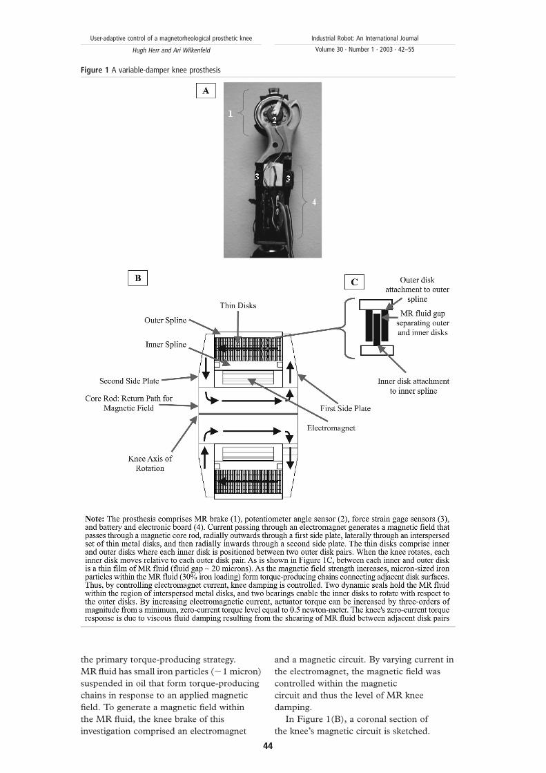
Figure 1 A variable-damper knee prosthesis
User-adaptive control of a magnetorheological prosthetic knee
Hugh Herr and Ari Wilkenfeld
Industrial Robot: An International Journal
Volume 30 · Number 1 · 2003 · 42–55
44
When current was applied to the knee’s
electromagnet, a magnetic field was generated
through a return path centered about the
knee’s rotary axis. The field then moved
radially outwards through a first side plate,
laterally through an interspersed set of inner
and outer metal disks, and then radially
inwards through a second side plate. Inside
the knee, each outer and inner disk was
shaped like a concentric ring about the knee’s
axis of rotation. Furthermore, as is shown in
Figure 1(C), each outer disk was coupled to
an outer spline, and each inner disk was
coupled to an inner spline. When the knee was
flexed, the inner spline rotated with respect to
the outer spline, and therefore each inner disk
rotated with respect to two outer disk pairs.
Injected between each inner and outer disk
was a thin film of MR fluid (,20 micron gap).
When a magnetic field passed through the
stack of disks perpendicular to each disk
surface, MR damping developed in response
to the applied field. MR chains developed
within the fluid, connecting each lower disk
surface to an adjacent upper disk surface.
These chains further enhanced the required
torque necessary to rotate the knee, or to
shear a lower disk surface relative to an upper
disk surface. For a more detailed description
of the knee actuator technology, see
Deffenbaugh et al. (2001).
Sensors, microprocessor and battery
To control knee resistive torque, the
prosthesis of this investigation used only local
mechanical sensing of knee position, force
and torque. Here the phrase “local sensing”
means that all sensors were positioned
relatively close to the knee axis (,10 cm),
allowing amputee’s to employ vertical shock
pylon technologies critical to overall
prosthesis shock absorption. Angle sensor (2)
in Figure 1 (custom built potentiometer,
15 kV) measured knee flexion angle. The
angle signal was then differentiated in analog
circuitry to estimate knee angular velocity.
Knee velocity was critical for determining
whether the knee was flexing or extending.
Axial force sensors (3) in Figure 1 (two aft
and two fore strain gages) measured the
component of force applied to the knee
prosthesis from the ground in the direction of
the knee’s longitudinal axis (add fore and aft
strain gage signals). The axial force
measurement was critical for determining
whether the prosthetic foot was on or off
the ground. The strain gage sensors were also
used to measure knee torque (subtract fore
from aft strain gage signals). Throughout
early stance in walking, when only the heel
was loaded, the torque sensor measured a
positive flexion moment, denoting that the
amputee’s load line was posterior to the
knee’s rotational axis and the knee prosthesis
was at risk of buckling. In distinction, during
late stance, when only the toe was loaded, the
torque sensor measured a negative extension
moment, denoting that the load line was
anterior to the knee’s rotational axis and the
prosthesis was not at risk of buckling. As will
be described in the next section, the
controller changed from high to low damping
depending on heel versus toe loading
conditions, respectively. For this
investigation, a 6812 Motorola
microprocessor was used for computation,
and four rechargeable lithium ion batteries
were employed for power.
MR knee prosthesis: control algorithm
Description of normal, level-ground walking:
To describe how the electronic knee
prosthesis was controlled, the basic walking
progression must first be explained. There
are five distinct phases to a walking gait
cycle (Inman, 1981).
(1) Beginning with heel strike, the stance
knee begins to flex slightly. This flexion
allows for shock absorption upon impact
as well as keeping the body’s center of
gravity at a more constant vertical level
throughout stance.
(2) After maximum flexion is reached in the
stance knee, the joint begins to extend
again, until maximum extension is
reached.
(3) During late stance, the knee of the
supporting leg begins to flex again in
preparation for leaving the ground for
swing. This is referred to in the literature
as “knee break” or “pre-swing”. At this
time, the adjacent foot strikes the ground
and the body is in “double support mode”
(that is to say, both legs are supporting
body weight).
(4) As the hip is flexed, and the knee has
reached a certain angle in knee break, the
leg leaves the ground and the knee
continues to flex.
(5) After reaching a maximum flexion angle
during swing, the knee begins to extend.
After the knee has reached full extension,
User-adaptive control of a magnetorheological prosthetic knee
Hugh Herr and Ari Wilkenfeld
Industrial Robot: An International Journal
Volume 30 · Number 1 · 2003 · 42–55
45
the foot once again is placed on the
ground, and the next walking cycle
begins.
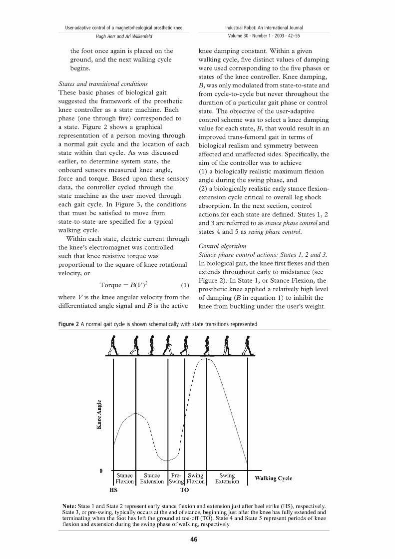
States and transitional conditions
These basic phases of biological gait
suggested the framework of the prosthetic
knee controller as a state machine. Each
phase (one through five) corresponded to
a state. Figure 2 shows a graphical
representation of a person moving through
a normal gait cycle and the location of each
state within that cycle. As was discussed
earlier, to determine system state, the
onboard sensors measured knee angle,
force and torque. Based upon these sensory
data, the controller cycled through the
state machine as the user moved through
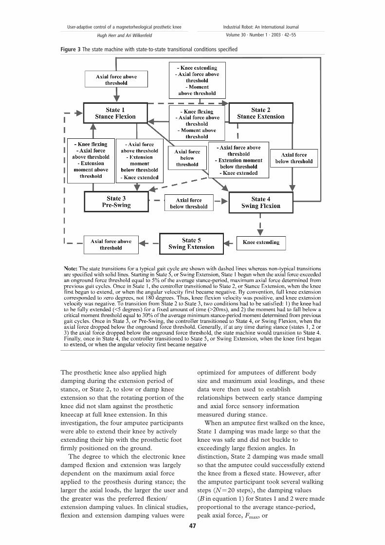
each gait cycle. In Figure 3, the conditions
that must be satisfied to move from
state-to-state are specified for a typical
walking cycle.
Within each state, electric current through
the knee’s electromagnet was controlled
such that knee resistive torque was
proportional to the square of knee rotational
velocity, or
Torque ¼ BðV Þ2 ð1Þ
where V is the knee angular velocity from the
differentiated angle signal and B is the active
knee damping constant. Within a given
walking cycle, five distinct values of damping
were used corresponding to the five phases or
states of the knee controller. Knee damping,
B, was only modulated from state-to-state and
from cycle-to-cycle but never throughout the
duration of a particular gait phase or control
state. The objective of the user-adaptive
control scheme was to select a knee damping
value for each state, B, that would result in an
improved trans-femoral gait in terms of
biological realism and symmetry between
affected and unaffected sides. Specifically, the
aim of the controller was to achieve
(1) a biologically realistic maximum flexion
angle during the swing phase, and
(2) a biologically realistic early stance flexion-
extension cycle critical to overall leg shock
absorption. In the next section, control
actions for each state are defined. States 1, 2
and 3 are referred to as stance phase control and
states 4 and 5 as swing phase control.
Control algorithm
Stance phase control actions: States 1, 2 and 3.
In biological gait, the knee first flexes and then
extends throughout early to midstance (see
Figure 2). In State 1, or Stance Flexion, the
prosthetic knee applied a relatively high level
of damping (B in equation 1) to inhibit the
knee from buckling under the user’s weight.
Figure 2 A normal gait cycle is shown schematically with state transitions represented
User-adaptive control of a magnetorheological prosthetic knee
Hugh Herr and Ari Wilkenfeld
Industrial Robot: An International Journal
Volume 30 · Number 1 · 2003 · 42–55
46
The prosthetic knee also applied high
damping during the extension period of
stance, or State 2, to slow or damp knee
extension so that the rotating portion of the
knee did not slam against the prosthetic
kneecap at full knee extension. In this
investigation, the four amputee participants
were able to extend their knee by actively
extending their hip with the prosthetic foot
firmly positioned on the ground.
The degree to which the electronic knee
damped flexion and extension was largely
dependent on the maximum axial force
applied to the prosthesis during stance; the
larger the axial loads, the larger the user and
the greater was the preferred flexion/
extension damping values. In clinical studies,
flexion and extension damping values were
optimized for amputees of different body
size and maximum axial loadings, and these
data were then used to establish
relationships between early stance damping
and axial force sensory information
measured during stance.
When an amputee first walked on the knee,
State 1 damping was made large so that the
knee was safe and did not buckle to
exceedingly large flexion angles. In
distinction, State 2 damping was made small
so that the amputee could successfully extend
the knee from a flexed state. However, after
the amputee participant took several walking
steps (N¼20 steps), the damping values
(B in equation 1) for States 1 and 2 were made
proportional to the average stance-period,
peak axial force, Fmax, or
Figure 3 The state machine with state-to-state transitional conditions specified
User-adaptive control of a magnetorheological prosthetic knee
Hugh Herr and Ari Wilkenfeld
Industrial Robot: An International Journal
Volume 30 · Number 1 · 2003 · 42–55
47
B ¼ AðFmaxÞ ð2Þ
where A is a proportionality constant
determined to give biologically realistic early
stance flexion-extension dynamics during
previously conducted clinical investigations.
With this control approach, no user-specific
information was programmed into the
prosthetic knee. Using sensory information
measured local to the knee prosthesis, stance
resistances were automatically adapted to the
needs of the amputee.
State 3: In State 3, or pre-swing,
electromagnet current, or knee active
damping B, was set equal to zero. Here the
knee’s zero-current torque response was due
to viscous fluid damping resulting from the
shearing of MR fluid between adjacent disk
pairs (see Figure 1).
Swing phase control actions: States 4 and 5.
During the stance period of a gait cycle, the
knee sensors measured a parameter that
changed monotonically with locomotory
speed. In this investigation, the amount of
time the prosthetic foot remained in contact
with the ground or foot contact time, was
used. As amputee participants walked at
increasingly faster speeds, their foot contact
time steadily decreased. This basic trend also
holds for non-amputees (Wilkenfeld, 2000).
Through an iterative process, the user-
adaptive controller determined how swing
phase damping should change with foot
contact time or walking speed. Stored in the
memory of the knee’s processor was the full
biological range of foot contact time. A person
of short stature has, on average, smaller foot
contact times compared with a person of tall
stature. The full biological range stored in
memory included both these extremes.
For this investigation, 0-2 s was more than
sufficient to cover the full biological range of
foot contact times. This range was partitioned
into time slots. A reasonable partition size was
40 ms, giving a total of 50 time slots over the
two-second interval. Any one amputee
sampled not all but a fraction of the 50 time
slots when moving from a slow to a fast
walking pace. Since the entire biological range
was partitioned, each amputee, independent
of height, sampled multiple time slots when
accelerating from a slow to a fast speed.
Within each time slot, swing phase flexion
damping (B in equation 1) was modulated to
control the maximum flexion angle in State 4.
When the amputee participants first used the
knee prosthesis controlled by this scheme,
State 4 damping was set equal to zero (zero
electromagnet current) within each time slot.
Hence, when the amputee participants took
their first step, State 4 damping was
minimized, and the knee swung freely
throughout the early swing phase. However,
for subsequent steps, the controller increased
the level of active damping whenever the knee
flexed to an angle greater than a fixed target
angle. Maximum flexion angle during early
swing typically does not exceed 70 degrees in
normal walking (Inman, 1981). Hence, to
achieve a gait cycle that appears natural or
biological, the target angle was set equal to
70 degrees. The amount that damping was
increased was proportional to the error
between the actual peak flexion angle,
measured by the angle sensor (see Figure 1),
and the target angle. Increased damping
lowered the peak flexion angle in future gait
cycles, but only in those time slots or walking
speeds for which the amputee had sampled.
Knee damping was decreased when the peak
flexion angle fell below the target angle for
N consecutive walking steps (N¼20 gait
cycles), ensuring that damping levels would
not be unnecessarily high.
As an amputee participant continued to use
the prosthesis, sampling a diverse range of
walking speeds, knee damping gradually
converged within each time slot until peak
knee flexion always fell below, or close to,
the target angle for all walking speeds.
Hence, once this adaptive scheme was
complete, the amputee could rapidly
accelerate from a slow to a fast walk all the
while sampling different time slots, and
therefore, different active damping levels
within State 4.
When the amputee participants took their
first walking steps, the user-adaptive knee
extended from the maximum flexion angle
in State 4 to full knee extension in State 5
(extended knee ¼ zero degrees) with knee
damping, B, set equal to zero. However, for
subsequent gait cycles, State 5 damping was
gradually increased within the time slots
or walking speeds sampled by the amputee
participant. The amount of damping increase
in State 5 was proportional to the current level
of damping in State 4. The level of extension
damping during swing was largely dependent
on the amount of damping required to
constrain the maximum flexion angle to 70
degrees; the larger the flexion damping, the
User-adaptive control of a magnetorheological prosthetic knee
Hugh Herr and Ari Wilkenfeld
Industrial Robot: An International Journal
Volume 30 · Number 1 · 2003 · 42–55
48
larger the user (and lower limb moment of
inertia) and the greater was the required State
5 extension damping. In clinical studies,
extension damping values were optimized for
amputees of different body size and lower limb
moments of inertia, and these data were then
used to establish a functional relationship
between extension and flexion damping.
As the amputee participants continued to
use the prosthesis, sampling a diverse range of
walking speeds, State 5 damping gradually
converged within each time slot (since State 4
damping was convergent). Once the State 4
adaptation scheme was complete, the
amputee could rapidly accelerate from a slow
to a fast walk all the while sampling different
time slots, and therefore, different State 5
damping levels.
Clinical evaluation
Subjects
The clinical evaluation of the electronic knee
was conducted in the Gait Laboratory at
Spaulding Rehabilitation Hospital, Boston,
MA. Protocol approval was provided by the
Spaulding Rehabilitation Hospital and Boston
University School of Medicine institutional
review boards. Moreover, a written informed
consent was obtained from each participant
before data collection began.
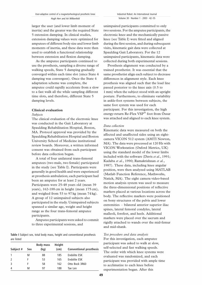
A total of four unilateral trans-femoral
amputees (two male, two female) participated
in the study (see Table I). Participants were
generally in good health and were experienced
at prosthesis ambulation; each participant had
been an amputee for at least 2 years.
Participants were 25-48 years old (mean 39
years), 162-188 cm in height (mean 175 cm),
and weighed from 53 to 97 kg (mean 74 kg).
A group of 12 unimpaired subjects also
participated in the study. Unimpaired subjects
spanned a similar age, weight and height
range as the four trans-femoral amputee
participants.
Amputee participants were asked to commit
to three experimental sessions, and
unimpaired participants committed to only
two sessions. For the amputee participants, the
electronic knee and the mechanically passive
knee (see Table I) were fitted and aligned
during the first session, and during subsequent
visits, kinematic gait data were collected at
Spaulding Gait Laboratory. For the 12
unimpaired participants, kinematic data were
collected during both experimental sessions.
Prosthesis alignment was conducted by a
trained prosthetist. It was essential that the
same prosthetist align each subject to decrease
differences in alignment style. Each knee
prosthesis was aligned such that the load line
passed posterior to the knee axis (0.5 to
1 mm) when the subject stood with an upright
posture. Furthermore, to eliminate variability
in ankle-foot systems between subjects, the
same foot system was used for each
participant. For this investigation, the high
energy-return Re-Flex VSPw foot from Ossur
was attached and aligned to each knee system.
Data collection
Kinematic data were measured on both the
affected and unaffected sides using an eight-
camera VICON 512 system (AMTI Newton,
MA). The data were processed at 120 Hz with
VICON Workstation (Oxford Metrics, UK)
using the standard model of the lower limbs
included with the software (Davis et al., 1991;
Kadaba et al., 1990; Ramakrishnan et al.,
1987). These data, including knee angular
position, were then analyzed using MATLAB
(Matlab Function Reference, Mathworks,
Natick, MA). The eight camera video-based
motion analysis system was used to measure
the three-dimensional positions of reflective
markers placed at various locations across the
body. The reflective markers were positioned
on bony structures of the pelvis and lower
extremities – bilateral anterior superior iliac
spines, lateral femoral condyles, lateral
malleoli, forefeet, and heels. Additional
markers were placed over the sacrum and
rigidly attached to wands over the mid-femur
and mid-shank.
Test procedure and data analysis
For this investigation, each amputee
participant was asked to walk at slow,
self-selected and fast walking speeds.
The order with which knee systems were
evaluated was randomized, and each
participant was provided with ample time
to acclimatize to each knee before
experimentation began. After this
Table I Subject sex, total body mass, height and conventional prosthesis
are listed
Subject # Sex
Body mass
(kg)
Height
(cm) Conventional prosthesis
1 M 88 185 Endolite ESK
2 F 53 165 Endolite ESK
3 F 58 162 Otto Bock 3R60
4 M 97 188 Tae Len
User-adaptive control of a magnetorheological prosthetic knee
Hugh Herr and Ari Wilkenfeld
Industrial Robot: An International Journal
Volume 30 · Number 1 · 2003 · 42–55
49
habituation, approximately ten walking trials
of kinematic data were collected for each
steady state speed and knee condition.
Kinematic data were also collected on 12
unimpaired participants. Approximately ten
walking trials were collected for each steady
state speed with a total of 17 different speeds
evaluated across a speed range of 0.3-1.8 m/s.
For each participant, experimental trial and
control condition, both the maximum knee
flexion angle during early stance and the
maximum swing flexion angle were computed
from the kinematic data. For the amputee
participants, both the affected and unaffected
sides were analyzed to assess the level of gait
symmetry.
Results
Early stance knee flexion
When using the user-adaptive knee prosthesis,
all four amputee participants demonstrated
early stance knee flexion. At the self-selected
walking speed, the maximum flexion angle
during early stance was 8^4 degrees.
However, no early stance flexion was observed
with the mechanically passive prostheses.
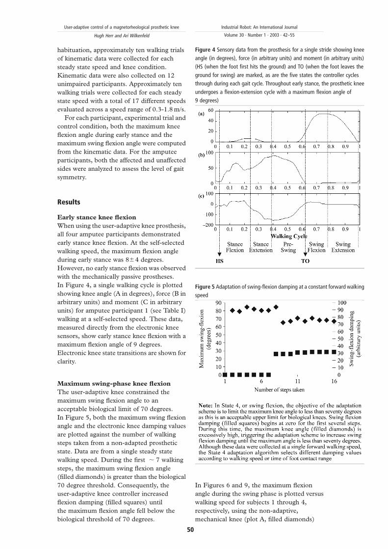
In Figure 4, a single walking cycle is plotted
showing knee angle (A in degrees), force (B in
arbitrary units) and moment (C in arbitrary
units) for amputee participant 1 (see Table I)
walking at a self-selected speed. These data,
measured directly from the electronic knee
sensors, show early stance knee flexion with a
maximum flexion angle of 9 degrees.
Electronic knee state transitions are shown for
clarity.
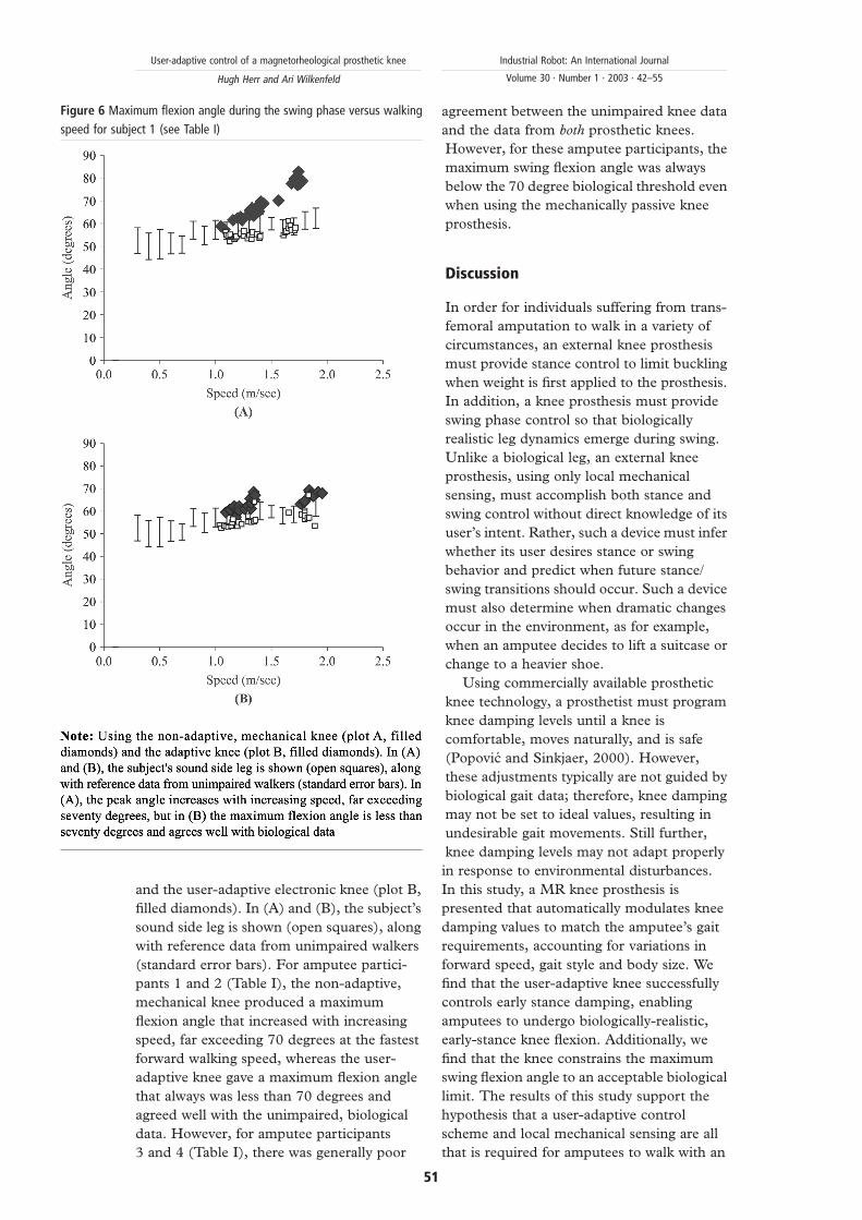
Maximum swing-phase knee flexion
The user-adaptive knee constrained the
maximum swing flexion angle to an
acceptable biological limit of 70 degrees.
In Figure 5, both the maximum swing flexion
angle and the electronic knee damping values
are plotted against the number of walking
steps taken from a non-adapted prosthetic
state. Data are from a single steady state
walking speed. During the first , 7 walking
steps, the maximum swing flexion angle
(filled diamonds) is greater than the biological
70 degree threshold. Consequently, the
user-adaptive knee controller increased
flexion damping (filled squares) until
the maximum flexion angle fell below the
biological threshold of 70 degrees.
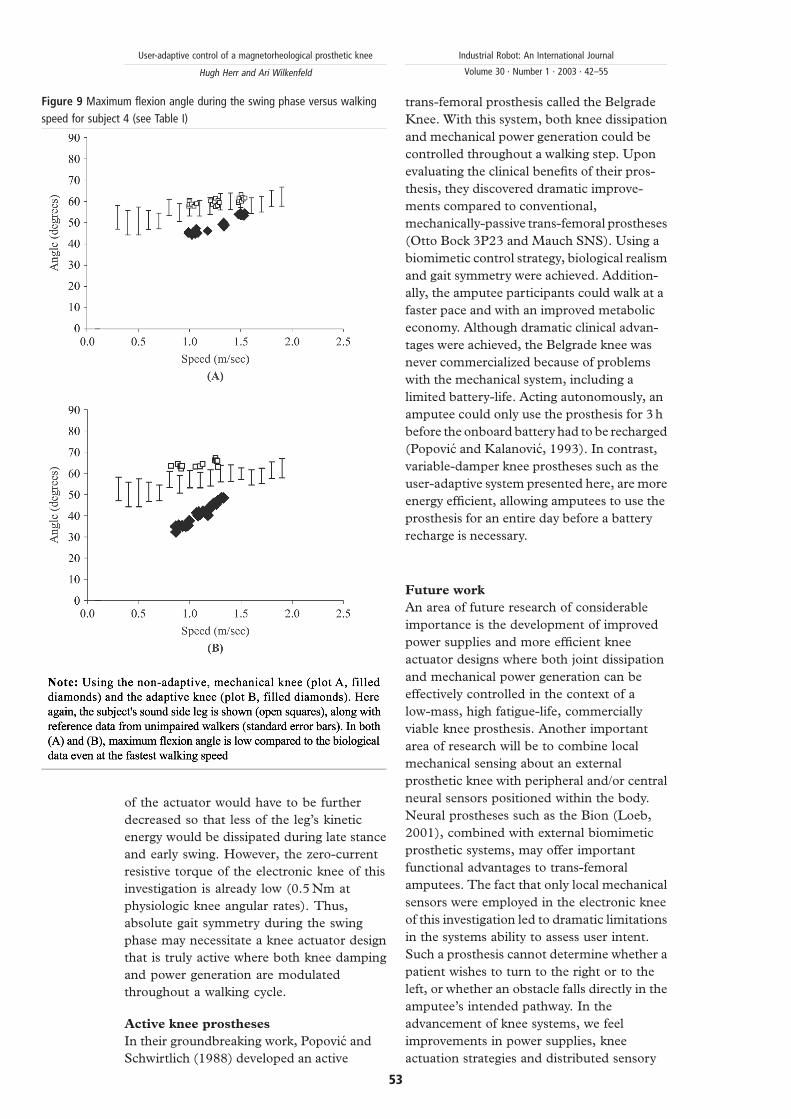
In Figures 6 and 9, the maximum flexion
angle during the swing phase is plotted versus
walking speed for subjects 1 through 4,
respectively, using the non-adaptive,
mechanical knee (plot A, filled diamonds)
Figure 5 Adaptation of swing-flexion damping at a constant forward walking
speed
Figure 4 Sensory data from the prosthesis for a single stride showing knee
angle (in degrees), force (in arbitrary units) and moment (in arbitrary units)
(HS (when the foot first hits the ground) and TO (when the foot leaves the
ground for swing) are marked, as are the five states the controller cycles
through during each gait cycle. Throughout early stance, the prosthetic knee
undergoes a flexion-extension cycle with a maximum flexion angle of
9 degrees)
User-adaptive control of a magnetorheological prosthetic knee
Hugh Herr and Ari Wilkenfeld
Industrial Robot: An International Journal
Volume 30 · Number 1 · 2003 · 42–55
50
and the user-adaptive electronic knee (plot B,
filled diamonds). In (A) and (B), the subject’s
sound side leg is shown (open squares), along
with reference data from unimpaired walkers
(standard error bars). For amputee partici-
pants 1 and 2 (Table I), the non-adaptive,
mechanical knee produced a maximum
flexion angle that increased with increasing
speed, far exceeding 70 degrees at the fastest
forward walking speed, whereas the user-
adaptive knee gave a maximum flexion angle
that always was less than 70 degrees and
agreed well with the unimpaired, biological
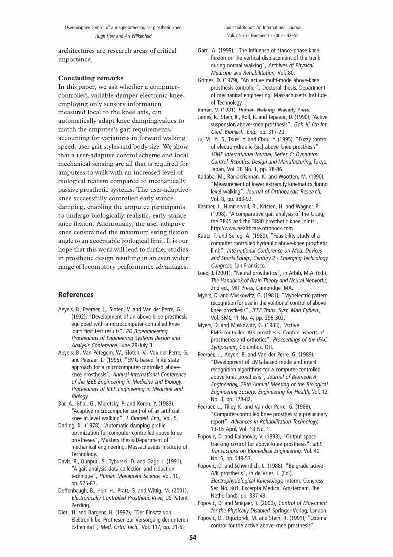
data. However, for amputee participants
3 and 4 (Table I), there was generally poor
agreement between the unimpaired knee data
and the data from both prosthetic knees.
However, for these amputee participants, the
maximum swing flexion angle was always
below the 70 degree biological threshold even
when using the mechanically passive knee
prosthesis.
Discussion
In order for individuals suffering from trans-
femoral amputation to walk in a variety of
circumstances, an external knee prosthesis
must provide stance control to limit buckling
when weight is first applied to the prosthesis.
In addition, a knee prosthesis must provide
swing phase control so that biologically
realistic leg dynamics emerge during swing.
Unlike a biological leg, an external knee
prosthesis, using only local mechanical
sensing, must accomplish both stance and
swing control without direct knowledge of its
user’s intent. Rather, such a device must infer
whether its user desires stance or swing
behavior and predict when future stance/
swing transitions should occur. Such a device
must also determine when dramatic changes
occur in the environment, as for example,
when an amputee decides to lift a suitcase or
change to a heavier shoe.
Using commercially available prosthetic
knee technology, a prosthetist must program
knee damping levels until a knee is
comfortable, moves naturally, and is safe
(Popovic and Sinkjaer, 2000). However,
these adjustments typically are not guided by
biological gait data; therefore, knee damping
may not be set to ideal values, resulting in
undesirable gait movements. Still further,
knee damping levels may not adapt properly
in response to environmental disturbances.
In this study, a MR knee prosthesis is
presented that automatically modulates knee
damping values to match the amputee’s gait
requirements, accounting for variations in
forward speed, gait style and body size. We
find that the user-adaptive knee successfully
controls early stance damping, enabling
amputees to undergo biologically-realistic,
early-stance knee flexion. Additionally, we
find that the knee constrains the maximum
swing flexion angle to an acceptable biological
limit. The results of this study support the
hypothesis that a user-adaptive control
scheme and local mechanical sensing are all
that is required for amputees to walk with an
Figure 6 Maximum flexion angle during the swing phase versus walking
speed for subject 1 (see Table I)
User-adaptive control of a magnetorheological prosthetic knee
Hugh Herr and Ari Wilkenfeld
Industrial Robot: An International Journal
Volume 30 · Number 1 · 2003 · 42–55
51

increased level of biological realism compared
to mechanically passive prosthetic systems.
Dissipative knees and swing phase gait
symmetry
Although the peak swing flexion angles
measured from amputee participants 1 and 2
agreed well with the unimpaired, biological
data (Figures 6 and 7), the data from
amputee participants 3 and 4 did not. The
peak swing flexion angles from these
participants were generally much lower than
the unimpaired, biological data even when
using the non-adaptive passive knees
(Figures 8 and 9). Since the electronic knee
of this investigation is purely dissipative and
cannot power movement, a peak swing
flexion angle that falls below the 70 degree
threshold cannot be increased by the system
if the knee’s active damping is already set to
zero (electromagnet current ¼ 0). Hence, for
participants 3 and 4, the electronic knee
controller set flexion damping equal to zero
in an attempt to increase both the peak flexion
angle and the level of gait symmetry between
affected and unaffected sides. Only changes
to the knee actuator design, not control
system, would improve the biological realism
and gait symmetry of participants 3 and 4.
To increase the peak flexion angle for these
individuals, the zero-current resistive torque
Figure 7 Maximum flexion angle during the swing phase versus walking
speed for subject 2 (see Table I) Figure 8 Maximum flexion angle during the swing phase versus walking
speed for subject 3 (see Table I)
User-adaptive control of a magnetorheological prosthetic knee
Hugh Herr and Ari Wilkenfeld
Industrial Robot: An International Journal
Volume 30 · Number 1 · 2003 · 42–55
52
of the actuator would have to be further
decreased so that less of the leg’s kinetic
energy would be dissipated during late stance
and early swing. However, the zero-current
resistive torque of the electronic knee of this
investigation is already low (0.5 Nm at
physiologic knee angular rates). Thus,
absolute gait symmetry during the swing
phase may necessitate a knee actuator design
that is truly active where both knee damping
and power generation are modulated
throughout a walking cycle.
Active knee prostheses
In their groundbreaking work, Popovic and
Schwirtlich (1988) developed an active
trans-femoral prosthesis called the Belgrade
Knee. With this system, both knee dissipation
and mechanical power generation could be
controlled throughout a walking step. Upon
evaluating the clinical benefits of their pros-
thesis, they discovered dramatic improve-
ments compared to conventional,
mechanically-passive trans-femoral prostheses
(Otto Bock 3P23 and Mauch SNS). Using a
biomimetic control strategy, biological realism
and gait symmetry were achieved. Addition-
ally, the amputee participants could walk at a
faster pace and with an improved metabolic
economy. Although dramatic clinical advan-
tages were achieved, the Belgrade knee was
never commercialized because of problems
with the mechanical system, including a
limited battery-life. Acting autonomously, an
amputee could only use the prosthesis for 3 h
before the onboard battery had to be recharged
(Popovic and Kalanovic, 1993). In contrast,
variable-damper knee prostheses such as the
user-adaptive system presented here, are more
energy efficient, allowing amputees to use the
prosthesis for an entire day before a battery
recharge is necessary.
Future work
An area of future research of considerable
importance is the development of improved
power supplies and more efficient knee
actuator designs where both joint dissipation
and mechanical power generation can be
effectively controlled in the context of a
low-mass, high fatigue-life, commercially
viable knee prosthesis. Another important
area of research will be to combine local
mechanical sensing about an external
prosthetic knee with peripheral and/or central
neural sensors positioned within the body.
Neural prostheses such as the Bion (Loeb,
2001), combined with external biomimetic
prosthetic systems, may offer important
functional advantages to trans-femoral
amputees. The fact that only local mechanical
sensors were employed in the electronic knee
of this investigation led to dramatic limitations
in the systems ability to assess user intent.
Such a prosthesis cannot determine whether a
patient wishes to turn to the right or to the
left, or whether an obstacle falls directly in the
amputee’s intended pathway. In the
advancement of knee systems, we feel
improvements in power supplies, knee
actuation strategies and distributed sensory
Figure 9 Maximum flexion angle during the swing phase versus walking
speed for subject 4 (see Table I)
User-adaptive control of a magnetorheological prosthetic knee
Hugh Herr and Ari Wilkenfeld
Industrial Robot: An International Journal
Volume 30 · Number 1 · 2003 · 42–55
53
architectures are research areas of critical
importance.
Concluding remarks
In this paper, we ask whether a computer-
controlled, variable-damper electronic knee,
employing only sensory information
measured local to the knee axis, can
automatically adapt knee damping values to
match the amputee’s gait requirements,
accounting for variations in forward walking
speed, user gait styles and body size. We show
that a user-adaptive control scheme and local
mechanical sensing are all that is required for
amputees to walk with an increased level of
biological realism compared to mechanically
passive prosthetic systems. The user-adaptive
knee successfully controlled early stance
damping, enabling the amputee participants
to undergo biologically-realistic, early-stance
knee flexion. Additionally, the user-adaptive
knee constrained the maximum swing flexion
angle to an acceptable biological limit. It is our
hope that this work will lead to further studies
in prosthetic design resulting in an even wider
range of locomotory performance advantages.
References
Aeyels, B., Peeraer, L., Sloten, V. and Van der Perre, G.(1992), “Development of an above-knee prosthesisequipped with a microcomputer-controlled kneejoint: first test results”, PD BioengineeringProceedings of Engineering Systems Design andAnalysis Conference, June 29-July 3.
Aeyels, B., Van Petegem, W., Sloten, V., Van der Perre, G.and Peeraer, L. (1995), “EMG-based finite stateapproach for a microcomputer-controlled above-knee prosthesis”, Annual International Conferenceof the IEEE Engineering in Medicine and Biology,Proceedings of IEEE Engineering in Medicine andBiology.
Bar, A., Ishai, G., Meretsky, P. and Koren, Y. (1983),“Adaptive microcomputer control of an artificialknee in level walking”, J. Biomed. Eng., Vol. 5.
Darling, D., (1978), “Automatic damping profileoptimization for computer controlled above-kneeprostheses”, Masters thesis Department ofmechanical engineering, Massachusetts Institute ofTechnology.
Davis, R., Ounpuu, S., Tyburski, D. and Gage, J. (1991),“A gait analysis data collection and reductiontechnique”, Human Movement Science, Vol. 10,pp. 575-87.
Deffenbaugh, B., Herr, H., Pratt, G. and Wittig, M. (2001),Electronically Controlled Prosthetic Knee, US PatentPending.
Dietl, H. and Bargehr, H. (1997), “Der Einsatz vonElektronik bei Prothesen zur Versorgung der unterenExtremitat”, Med. Orth. Tech., Vol. 117, pp. 31-5.
Gard, A. (1999), “The influence of stance-phase kneeflexion on the vertical displacement of the trunkduring normal walking”, Archives of PhysicalMedicine and Rehabilitation, Vol. 80.
Grimes, D. (1979), “An active multi-mode above-kneeprosthesis controller”, Doctoral thesis, Departmentof mechanical engineering, Massachusetts Instituteof Technology.
Inman, V. (1981), Human Walking, Waverly Press.James, K., Stein, R., Rolf, R. and Tepavac, D. (1990), “Active
suspension above-knee prosthesis”, Goh JC 6th Int.Conf. Biomech. Eng., pp. 317-20.
Ju, M., Yi, S., Tsuei, Y. and Chou, Y. (1995), “Fuzzy controlof electrohydraulic [sic] above knee prosthesis”,JSME International Journal, Series C: Dynamics,Control, Robotics, Design and Manufacturing, Tokyo,Japan, Vol. 38 No. 1, pp. 78-86.
Kadaba, M., Ramakrishnan, K. and Wootten, M. (1990),“Measurement of lower extremity kinematics duringlevel walking”, Journal of Orthopaedic Research,Vol. 8, pp. 383-92.
Kastner, J., Nimmervoll, R., Kristen, H. and Wagner, P.(1998), “A comparative gait analysis of the C-Leg,the 3R45 and the 3R80 prosthetic knee joints”,http://www.healthcare.ottobock.com
Kautz, T. and Seireg, A. (1980), “Feasibility study of acomputer controlled hydraulic above-knee prostheticlimb”, International Conference on Med. Devicesand Sports Equip., Century 2 - Emerging TechnologyCongress, San Francisco.
Loeb, J. (2001), “Neural prosthetics”, in Arbib, M.A. (Ed.),The Handbook of Brain Theory and Neural Networks,2nd ed., MIT Press, Cambridge, MA.
Myers, D. and Moskowitz, G. (1981), “Myoelectric patternrecognition for use in the volitional control of above-knee prosthesis”, IEEE Trans. Syst. Man Cybern.,Vol. SMC-11 No. 4, pp. 296-302.
Myers, D. and Moskowitz, G. (1983), “ActiveEMG-controlled A/K prosthesis. Control aspects ofprosthetics and orthotics”, Proceedings of the IFACSymposium, Columbus, OH.
Peeraer, L., Aeyels, B. and Van der Perre, G. (1989),“Development of EMG-based mode and intentrecognition algorithms for a computer-controlledabove-knee prosthesis”, Journal of BiomedicalEngineering, 29th Annual Meeting of the BiologicalEngineering Society: Engineering for Health, Vol. 12No. 3, pp. 178-82.
Peeraer, L., Tilley, K. and Van der Perre, G. (1988),“Computer-controlled knee prosthesis: a preliminaryreport”, Advances in Rehabilitation Technology,13-15 April, Vol. 13 No. 1.
Popovic, D. and Kalanovic, V. (1993), “Output spacetracking control for above-knee prosthesis”, IEEETransactions on Biomedical Engineering, Vol. 40No. 6, pp. 549-57.
Popovic, D. and Schwirtlich, L. (1988), “Belgrade activeA/K prosthesis”, in de Vries, J. (Ed.),Electrophysiological Kinesiology, Interm. CongressSer. No. 804, Excerpta Medica, Amsterdam, TheNetherlands, pp. 337-43.
Popovic, D. and Sinkjaer, T. (2000), Control of Movementfor the Physically Disabled, Springer-Verlag, London.
Popovic, D., Oguztoreli, M. and Stein, R. (1991), “Optimalcontrol for the active above-knee prosthesis”,
User-adaptive control of a magnetorheological prosthetic knee
Hugh Herr and Ari Wilkenfeld
Industrial Robot: An International Journal
Volume 30 · Number 1 · 2003 · 42–55
54
Annals of Biomedical Engineering, Vol. 19 No. 2,pp. 131-50.
Ramakrishnan, H., Kadaba., M. and Wootten, M. (1987),“Lower extremity joint moments and groundreaction torque in adult gait”, in Stein, J.L. (Ed.),Biomechanics of Normal and Prosthetic Gait, ASMEWinter Annual Meeting, BED-Vol. 4, pp. 87-92.
Triolo, R. and Moskowitz, G. (1982), “Autoregressive EMGanalysis and prosthetic control”, Proceedings of the35th Annual Conference on Engineering in Medicineand Biology, Philadelphia, PA.
Wilkenfeld, A. An auto-adaptive external kneeprosthesis Doctoral Thesis Department ofmechanical engineering, Massachusetts Instituteof Technology.
Further reading
Goldfarb, M. (1992), “Control of a self-containedmicrocomputer-controlled above-knee prosthesis”Masters Thesis, Department of mechanicalengineering, Massachusetts Institute ofTechnology.
Herr, H., Wilkenfeld, A. and Olaf, B. (2001),Speed-Adaptive and Patient-Adaptive ProstheticKnee, US Patent Pending.
Qi, D. (1986), “A speed adaptive control algorithm for theself-contained A/K prosthesis” Masters thesis,Department of mechanical engineering,Massachusetts Institute of Technology.
User-adaptive control of a magnetorheological prosthetic knee
Hugh Herr and Ari Wilkenfeld
Industrial Robot: An International Journal
Volume 30 · Number 1 · 2003 · 42–55
55