features - carriercarrier.com.hk/comm/comm_new2010/2012 cat/air cooled/30rb192-8… · 30rb 192-802...
TRANSCRIPT
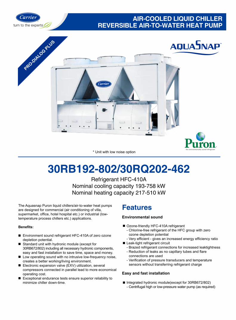
The Aquasnap Puron liquid chillers/air-to-water heat pumps are designed for commercial (air conditioning of villa, supermarket, office, hotel hospital etc.) or industrial (low-temperature process chillers etc.) applications.
Benefits:
Environment sound refrigerant HFC-410A of zero ozone depletion potential.Standard unit with hydronic module (except for 30RB672/802) including all necessary hydronic components, easy and fast installation to save time, space and money.Low operating sound with no intrusive low-frequency noise, creates a better working/living environment.Electronic expansion valve (EXV) utilization, several compressors connected in parallel lead to more economical operating cost. Exceptional endurance tests ensure superior reliability to minimize chiller down-time.
FeaturesEnvironmental sound
Ozone-friendly HFC-410A refrigerant- Chlorine-free refrigerant of the HFC group with zero ozone depletion potential- Very efficient - gives an increased energy efficiency ratioLeak-tight refrigerant circuit- Brazed refrigerant connections for increased leaktightness- Reduction of leaks as no capillary tubes and flare connections are used- Verification of pressure transducers and temperature sensors without transferring refrigerant charge
Easy and fast installation
Integrated hydronic module(except for 30RB672/802)- Centrifugal high or low-pressure water pump (as required)
30RB192-802/30RQ202-462Refrigerant HFC-410A
Nominal cooling capacity 193-758 kWNominal heating capacity 217-510 kW
AIR-COOLED LIQUID CHILLERREVERSIBLE AIR-TO-WATER HEAT PUMP
* Unit with low noise option
PRO-DIA
LOG PLUS
�
30RB 192-802 / 30RQ 202-462
Features
- Single or dual pump (as required) with operating time balancing and automatic changeover to the back-up pump if a fault develops- Water filter protects the water pump against circulating debris- High-capacity membrane expansion tank ensures pressurization of the water circuit- Thermal insulation and anti-freeze protection down to -20oC by using an electric resistance heaterSimplified electrical connections- A single power supply point without neutral (except for 30RB672/802)- Main disconnect switch with high trip capacity- Transformer for safe 24 V control circuit supply includedFast commissioning- Systematic factory operation test before shipment- Quick-test function for step-by-step verification of the instruments, electrical components and motors
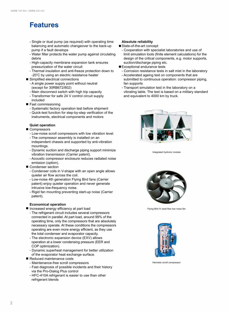
Quiet operationCompressors- Low-noise scroll compressors with low vibration level.- The compressor assembly is installed on an independent chassis and supported by anti-vibration mountings.- Dynamic suction and discharge piping support minimize vibration transmission (Carrier patent).- Acoustic compressor enclosure reduces radiated noise emission (option).Condenser section- Condenser coils in V-shape with an open angle allows quieter air flow across the coil.- Low-noise 4th generation Flying Bird fans (Carrier patent) enjoy quieter operation and never generate intrusive low-frequency noise.- Rigid fan mounting preventing start-up noise (Carrier patent).
Economical operationIncreased energy efficiency at part load- The refrigerant circuit includes several compressors connected in parallel. At part load, around 99% of the operating time, only the compressors that are absolutely necessary operate. At these conditions the compressors operating are even more energy efficient, as they use the total condenser and evaporator capacity.- The electronic expansion device (EXV) allows operation at a lower condensing pressure (EER and COP optimization).- Dynamic superheat management for better utilization of the evaporator heat exchange surface.Reduced maintenance costs- Maintenance-free scroll compressors- Fast diagnosis of possible incidents and their history via the Pro-Dialog Plus control- HFC-410A refrigerant is easier to use than other refrigerant blends
Absolute reliabilityState-of-the-art concept- Cooperation with specialist laboratories and use of limit simulation tools (finite element calculations) for the design of the critical components, e.g. motor supports, suction/discharge piping etc.Exceptional endurance tests- Corrosion resistance tests in salt mist in the laboratory- Accelerated ageing test on components that are submitted to continuous operation: compressor piping, fan supports- Transport simulation test in the laboratory on a vibrating table. The test is based on a military standard and equivalent to 4000 km by truck.
Integrated hydronic module
Flying Bird IV axial flow low noise fan
Hermetic scroll compressor
�
30RB 192-802 / 30RQ 202-462
Pro-Dialog Plus Control
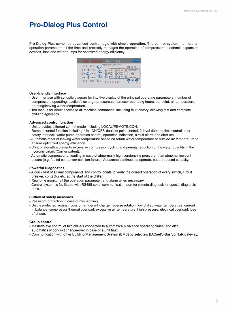
Pro-Dialog Plus combines advanced control logic with simple operation. The control system monitors all operation parameters all the time and precisely manages the operation of compressors, electronic expansion devices, fans and water pumps for optimized energy efficiency.
User-friendly interface- User interface with synoptic diagram for intuitive display of the principal operating parameters: number of compressors operating, suction/discharge pressure,compressor operating hours, set-point, air temperature, entering/leaving water temperature.- Ten menus for direct access to all machine commands, including fault history, allowing fast and complete chiller diagnostics.
Advanced control function- Unit provides different control mode including LOCAL/REMOTE/CCN.- Remote control function including: Unit ON/OFF, dual set point control, 2-level demand limit control, user safety interlock, water pump operation control, operation indication, circuit alarm and alert etc.- Automatic reset of leaving water temperature based on return water temperature or outside air temperature to ensure optimized energy efficiency.- Control algorithm prevents excessive compressor cycling and permits reduction of the water quantity in the hydronic circuit (Carrier patent).- Automatic compressor unloading in case of abnormally high condensing pressure. If an abnomal incident occurs (e.g. fouled condenser coil, fan failure), Aquasnap continues to operate, but at reduced capacity.
Powerful Diagnostics- A quick test of all unit components and control points to verify the correct operation of every switch, circuit breaker, contactor etc. at the start of the chiller.- Real-time monitor all the operation parameter, and alarm when necessary.- Control system is facilitated with RS485 serial communication port for remote diagnosis or special diagnosis tools.
Sufficient safety measures- Password protection in case of mishandling.- Unit is protected against: Loss of refrigerant charge, reverse rotation, low chilled water temperature, current imbalance, compressor thermal overload, excessive air temperature, high pressure, electrical overload, loss of phase.
Group control- Master/slave control of two chillers connected to automatically balance operating times, and also automatically conduct change-over in case of a unit fault.- Communication with other Building Management System (BMS) by selecting BACnet/J-Bus/LonTalk gateway.

�
30RB 192-802 / 30RQ 202-462
Technical Specifications
Performance data�0RB ��� ��� �0� 5�� ** **Nominal cooling capacity* kW 193 222 263 328 391 506 652 758 Compressor power input kW 64.3 66.9 91.2 113.0 137.1 178.7 224.8 269.0 EER kW/kW 2.7 3.0 2.7 2.7 2.7 2.6 2.7 2.6 Operating weightUnit with single pump hydronic module kg 2320 2330 2510 3320 3550 4480 - -Unit without hydronic module kg 2130 2140 2320 3120 3310 4190 5640 6510 Refrigerant HFC-410ACircuit A kg 24.0 24.0 24.0 37.0 38.5 47.5 38.5 48.0 Circuit B kg 24.0 24.0 24.0 26.0 38.5 47.5 38.5 48.0 Circuit C kg - - - - - - 48.0 48.0 Compressor Hermetic scroll compressorsCircuit A 1 2 2 3 3 4 3 4 Circuit B 2 2 2 2 3 4 3 4 Circuit C - - - - - - 4 4 Number of capacity stages 3 4 4 5 6 8 10 12 Minimum capacity % 33 25 25 20 17 13 10 8 Control Pro-Dialog PlusCondenser Grooved copper tubes and aluminium finsFans Axial Flying Bird IV with rotating shroudQuantity 4 4 4 5 6 8 10 12 Total air flow I/s 18056 18056 18056 22567 27081 36107 45134 54161 Speed rpm 960 960 960 960 960 960 960 960 Evaporator Direct expansion shell-and-tubeWater volume I 121 110 110 125 125 113 284 284 Nominal water flow rate l/s 9.2 10.6 12.6 15.6 18.7 24.1 31.0 36.1 Unit internal water pressure drop kPa 26 37 47 46 64 96 43 57 Max. water-side operating pressure without hydronic module kPa 1000 1000 1000 1000 1000 1000 1000 1000 Hydronic module Pump, victaulic screen filter, safety valve, expansion tank, purge valves etc. - -Water pump Centrifugal pump - -Water head external to chiller High pressure pump at nominal water flow rate kPa 177 205 181 182 201 210 - -Expansion tank I 50 50 50 80 80 80 - -Max. water-side operating pressure with hydronic module kPa 400 400 400 400 400 400 - -Water connection VictaulicDiameter (with hydronic module) DN100 DN100 DN100 DN100 DN100 DN125 - -Diameter (without hydronic module) DN100 DN100 DN100 DN100 DN100 DN150 DN150 DN150Electrical dataMain power supply 400V-3Ph-50HzControl power supply Via internal transformerNominal unit operating current draw, circuit A+B A 137 143 175 219 265 354 251 334 Nominal unit operating current draw, circuit C A - - - - - - 167 167 Maximum operating current draw, circuit A+B A 176 183 227 284 343 458 329 438 Maximum operating current draw, circuit C A - - - - - - 219 219 Maximum start-up current, circuit A+B A 383 356 434 492 551 667 535 645 Maximum start-up current, circuit C A - - - - - - 426 426 Total fan power input kW 6.4 6.4 6.4 7.9 9.5 12.7 15.9 19.1 Pump power input (high pressure single pump) kW 4.7 4.7 4.7 6.4 8.4 12.1 - -
* Nominal cooling mode - evaporator entering/leaving water temperature 12/7oC, outside air temperature 35oC, Evaporator fouling factor-0.018m2K/kW.
** Integrated hydronic module is not suitable for 30RB672/802.
�6�192 67� 80�**

5
30RB 192-802 / 30RQ 202-462
Technical Specifications
Performance data�0RQ 202 232 302 372 432 462 Nominal cooling capacity* kW 195 221 275 331 389 430 Compressor power input kW 65.8 70.8 98.1 115.8 139.1 153.6 EER kW/kW 2.7 2.9 2.6 2.6 2.6 2.6 Nominal heating capacity* kW 217 234 307 364 450 510 Compressor power input kW 68.8 71.8 102.1 116.8 147.1 167.6 COP kW/kW 2.9 3.0 2.8 2.9 2.8 2.8 Operating weightUnit with high-pressure single pump hydronic module kg 2425 2431 3245 3558 4268 4454 Unit without hydronic module kg 2235 2241 3045 3284 4028 4210 Refrigerant HFC-410ACircuit A kg 26.0 27.0 41.0 54.0 54.0 54.0 Circuit B kg 26.0 27.0 27.0 32.0 47.0 53.0 Compressor Hermetic scroll compressorsCircuit A 1 2 3 4 4 4 Circuit B 2 2 2 2 3 4 Number of capacity stages 3 4 5 6 7 8 Minimum capacity % 33 25 20 17 14 13 Control Pro-Dialog PlusAir heat exchanger Grooved copper tubes and aluminium finsFans Axial Flying Bird IV with rotating shroudQuantity 4 4 5 6 7 8 Total air flow I/s 18056 18056 22569 27083 31597 36111 Speed rpm 960 960 960 960 960 960 Water heat exchanger Direct expansion shell-and-tubeWater volume I 110 110 110 113 113 113 Nominal water flow rate, cooling mode l/s 9.4 10.3 13.6 16.4 19.3 21.7 Nominal water flow rate, heating mode l/s 10.5 10.9 15.2 18.0 22.3 25.7 Unit internal water pressure drop, cooling mode kPa 23 26 39 31 41 51 Unit internal water pressure drop, heating mode kPa 27 28 45 37 54 71 Max. water-side operating pressure without hydronic module kPa 1000 1000 1000 1000 1000 1000 Hydronic module Pump, victaulic screen filter, safety valve, expansion tank, purge valves etc.Water pump Centrifugal pump Water head external to chiller High pressure pump at nominal water flow rate, cooling mode kPa 173 211 183 225 198 245 High pressure pump at nominal water flow rate, heating mode kPa 162 203 164 205 152 178 Expansion tank I 50 50 80 80 80 80 Max. water-side operating pressure with hydronic module kPa 400 400 400 400 400 400 Water connection VictaulicDiameter (with hydronic module) DN100 DN100 DN100 DN125 DN125 DN125Diameter (without hydronic module) DN100 DN100 DN100 DN150 DN150 DN150Electrical dataMain power supply 400V-3Ph-50HzControl power supply Via internal transformerNominal unit operating current draw A 137 143 195 233 282 322 Maximum operating current draw A 176 183 251 299 364 414 Maximum start-up current A 383 356 459 507 573 623 Total fan power input kW 6.2 6.2 7.9 9.2 10.9 12.4 Pump power input (high pressure single pump) kW 4.7 4.7 6.4 8.5 8.5 12.2
* Nominal cooling mode - evaporator entering/leaving water temperature 12/7oC, outside air temperature 35oC; Nominal heating mode - water heat exchange entering/leaving water temperature 40/45°C, outside air temperature 7°C; Evaporator fouling factor - 0.018m2K/kW.
6
30RB 192-802 / 30RQ 202-462
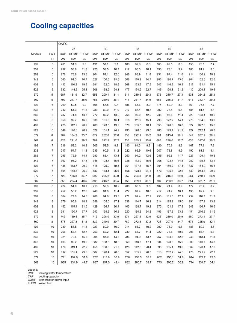
Cooling capacities
OAToC25 30 35 40 45
Models LWT CAP COMP FLOW CAP COMP FLOW CAP COMP FLOW CAP COMP FLOW CAP COMP FLOWoC kW kW l/s kW kW l/s kW kW l/s kW kW l/s kW kW l/s
192 5 201 51.9 9.6 191 57.1 9.1 180 62.9 8.6 168 69.1 8.0 155 76.1 7.4
232 5 237 53.8 11.3 225 59.5 10.7 212 66.0 10.1 196 73.1 9.4 180 81.2 8.6
262 5 278 73.8 13.3 264 81.1 12.6 248 88.9 11.8 231 97.4 11.0 214 106.9 10.2
342 5 345 91.3 16.4 327 100.5 15.6 308 110.2 14.7 286 120.7 13.6 264 132.5 12.6
402 5 412 110.8 19.6 391 122.0 18.6 368 133.9 17.5 342 146.9 16.3 316 161.4 15.1
522 5 532 144.5 25.3 506 158.9 24.1 477 174.2 22.7 445 190.8 21.2 412 209.3 19.6
672 5 687 181.9 32.7 653 200.1 31.1 614 219.5 29.3 573 240.7 27.3 531 264.2 25.3
802 5 799 217.7 38.0 758 239.0 36.1 714 261.7 34.0 665 286.2 31.7 615 313.7 29.3
192 6 209 52.5 9.9 198 57.8 9.4 186 63.6 8.9 174 69.9 8.3 161 76.8 7.7
232 6 242 54.3 11.5 230 60.0 11.0 217 66.4 10.3 202 73.5 9.6 185 81.5 8.8
262 6 287 74.8 13.7 272 82.2 13.0 256 90.0 12.2 238 98.6 11.4 220 108.1 10.5
342 6 356 92.7 16.9 338 101.8 16.1 318 111.6 15.1 296 122.2 14.1 273 134.0 13.0
402 6 425 112.2 20.2 403 123.5 19.2 379 135.5 18.1 353 148.6 16.8 327 327.0 15.6
522 6 549 146.6 26.2 522 161.1 24.9 493 176.6 23.5 460 193.4 21.9 427 212.1 20.3
672 6 707 184.2 33.7 672 202.6 32.0 633 222.1 30.2 591 243.4 28.1 547 267.1 26.1
802 6 823 221.0 39.2 782 242.5 37.2 735 265.3 35.0 686 290.0 32.7 635 317.6 30.2
192 7 216 53.2 10.3 205 58.5 9.8 193 64.3 9.2 180 70.6 8.6 167 77.6 7.9
232 7 247 54.7 11.8 235 60.5 11.2 222 66.9 10.6 207 73.8 9.9 190 81.9 9.1
262 7 295 75.9 14.1 280 83.4 13.4 263 91.2 12.6 245 99.8 11.7 227 109.4 10.8
342 7 367 94.2 17.5 348 103.4 16.6 328 113.0 15.6 305 123.7 14.5 282 135.6 13.4
402 7 438 113.7 20.9 416 125.0 19.8 391 137.1 18.7 364 150.2 17.4 337 164.9 16.1
522 7 564 148.5 26.9 537 163.1 25.6 506 178.7 24.1 473 195.6 22.6 439 214.5 20.9
672 7 728 186.8 34.7 692 205.2 33.0 652 224.8 31.0 608 246.2 29.0 564 270.1 26.9
802 7 850 224.4 40.5 806 246.2 38.4 758 269.0 36.1 707 293.9 33.7 654 321.7 31.1
192 8 224 54.0 10.7 213 59.3 10.2 200 65.0 9.6 187 71.4 8.9 172 78.4 8.2
232 8 252 55.2 12.0 240 61.0 11.4 227 67.4 10.8 212 74.2 10.1 195 82.2 9.3
262 8 304 77.0 14.5 288 84.6 13.8 271 92.4 12.9 253 101.0 12.1 234 110.7 11.2
342 8 379 95.8 18.1 359 105.0 17.1 338 114.7 16.1 314 125.2 15.0 291 137.2 13.9
402 8 452 115.4 21.5 429 126.7 20.4 403 138.7 19.2 375 151.9 17.9 348 166.7 16.6
522 8 581 150.7 27.7 552 165.3 26.3 520 180.8 24.8 486 197.9 23.2 451 216.9 21.5
672 8 749 189.4 35.7 712 208.0 33.9 671 227.5 32.0 626 249.0 29.9 580 273.1 27.7
802 8 878 227.8 41.8 832 249.9 39.7 780 272.8 37.2 728 297.9 34.7 674 325.9 32.1
192 10 239 55.5 11.4 227 60.9 10.9 214 66.7 10.2 200 73.0 9.5 185 80.0 8.8
232 10 266 56.4 12.7 253 62.2 12.1 239 68.7 11.4 222 75.5 10.6 205 83.1 9.8
262 10 321 79.4 15.3 305 87.0 14.6 286 94.9 13.7 267 103.6 12.8 248 113.4 11.8
342 10 403 99.2 19.2 382 108.6 18.3 359 118.3 17.1 334 128.8 15.9 309 140.7 14.8
402 10 479 119.1 22.9 455 130.6 21.7 428 142.5 20.4 398 155.4 19.0 369 170.4 17.6
522 10 617 155.4 29.5 587 170.4 28.0 552 185.9 26.3 513 202.7 24.5 476 221.9 22.7
672 10 791 194.9 37.8 752 213.8 35.9 708 233.5 33.8 662 255.1 31.6 614 279.2 29.3
802 10 935 234.9 44.7 887 257.5 42.4 832 280.7 39.7 773 306.2 36.9 714 334.7 34.1
Legend:LWT leaving water temperatureCAP cooling capacityCOMP compressor power inputFLOW water flow

7
30RB 192-802 / 30RQ 202-462
Operating Range, 30RB192-802
Evaporator water temperature°C Minimum Maximum
Entering water temperature at shut-down - 48Entering water temperature at start-up 6.8 40Entering water temperature during operation 6.8 25Leaving water temperature during operation 3.3 15
Condenser air temperature°C Minimum Maximum
840tinu dradnatSWith winter operation option (No. 28) -20 48With winter operation B option (No. 28B) -10 48
Operating range
Ent
erin
g ai
r tem
pera
ture
°C
Evaporator leaving water temperature °C
Note: Evaporator and condenser Δt = 5 K
Standard unit operating range. Operating range, unit equipped with options 28 or 28B “Winter operation”. In addition the unit must either be equipped with anti-freeze protection option for the evaporator and the hydronic module (if used), or the water loop must be protected against frost by the installer, using an anti-freeze solution.
3.3
-20
48
15
-10
Opt
ion
28B
Opt
ion
28
8
30RB 192-802 / 30RQ 202-462
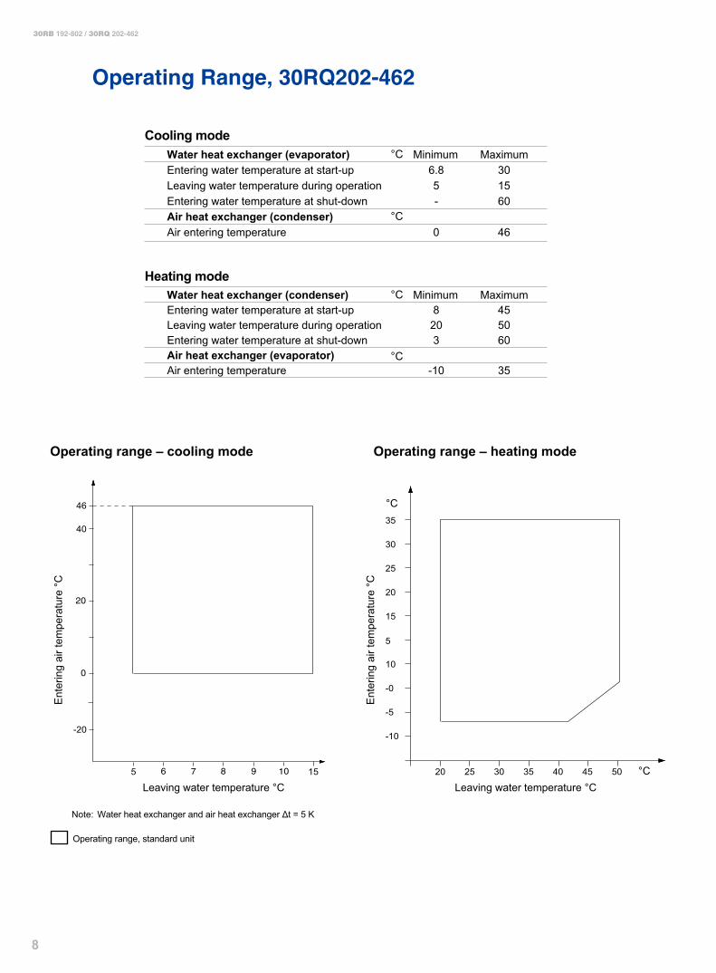
Operating Range, 30RQ202-462
Cooling modeWater heat exchanger (evaporator) Minimum MaximumEntering water temperature at start-up
°C6.8 30
Leaving water temperature during operation 5 15Entering water temperature at shut-down - 60Air heat exchanger (condenser)Air entering temperature 0 46
Heating modeWater heat exchanger (condenser) Minimum MaximumEntering water temperature at start-up
°C
°C
°C
8 45Leaving water temperature during operation 20 50Entering water temperature at shut-down 3 60Air heat exchanger (evaporator)Air entering temperature -10 35
Operating range – cooling mode
Ent
erin
g ai
r tem
pera
ture
°C
Leaving water temperature °C
Note: Water heat exchanger and air heat exchanger Δt = 5 K
Operating range, standard unit
5
-20
46
40
15
Operating range – heating mode
Ent
erin
g ai
r tem
pera
ture
°C
Leaving water temperature °C
°C
°C20 25 30 35 40 45 50
-10
-5
-0
5
10
15
20
25
30
35
9
30RB 192-802 / 30RQ 202-462
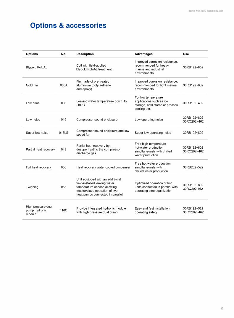
Options & accessories
Options No. Description Advantages Use
Blygold PoluAL 002B Coil with field-applied Blygold PoluAL treatment
Improved corrosion resistance, recommended for heavy marine and industrial environments
30RB192~802
Gold Fin 003AFin made of pre-treated aluminium (polyurethane and epoxy)
Improved corrosion resistance, recommended for light marine environments
30RB192~802
Low brine 006 Leaving water temperature down to -10 oC
For low temperature applications such as ice storage, cold stores or process cooling etc.
30RB192~402
Low noise 015 Compressor sound enclosure Low operating noise 30RB192~80230RQ202~462
Super low noise 015LS Compressor sound enclosure and low-speed fan Super low operating noise 30RB192~802
Partial heat recovery 049Partial heat recovery by desuperheating the compressor discharge gas
Free high-temperature hot-water production simultaneously with chilled water production
30RB192~80230RQ202~462
Full heat recovery 050 Heat recovery water cooled condenserFree hot water production simultaneously with chilled water production
30RB262~522
Twinning 058
Unit equipped with an additional field-installed leaving water temperature sensor, allowing master/slave operation of two heat pumps connected in parallel
Optimized operation of two units connected in parallel with operating time equalization
30RB192~80230RQ202-462
High pressure dual pump hydronic module
116C Provide integrated hydronic module with high pressure dual pump
Easy and fast installation, operating safety
30RB192~52230RQ202~462

10
30RB 192-802 / 30RQ 202-462
Options & accessories
Options No. Description Advantages Use
Unit without hydronic module 116D
Flexible for customer to purchase and install the water components by themselves
- 30RB192~80230RQ202~462
Low pressure single pump hydronic module
116FProvide integrated hydronic module with low pressure single pump
Easy and fast installation 30RB192~52230RQ202~462
Low pressure dual pump hydronic module
116GProvide integrated hydronic module with low pressure dual pump
Easy and fast installation, operating safety
30RB192~52230RQ202~462
Super high pressure single pump hydronic module
116HProvide integrated hydronic module with super high pressure single pump
Easy and fast installation 30RB192~52230RQ202~462
Super high pressure dual pump hydronic module
116IProvide integrated hydronic module with super high pressure dual pump
Easy and fast installation, operating safety
30RB192~52230RQ202~462
J-Bus gateway 148B Two-directional communication board with J-Bus protocol
Easy connection by communication bus to building management system
30RB192~80230RQ202~462
BacNet gateway 148C Two-directional communication board with BacNet protocol
Easy connection by communication bus to building management system
30RB192~80230RQ202~462
LonTalk gateway 148D Two-directional communication board with LonTalk protocol
Easy connection by communication bus to building management system
30RB192~80230RQ202~462
Cu/Al condenser coils 254 Coils made of copper tube with aluminium fin - 30RB192~802

11
30RB 192-802 / 30RQ 202-462
2297
368
2410
2457 2253
786
1500
A B
500
15001500
2200
1500
500
1500
2200
1500
1
1 1 2
2
1
1
1 1
1
2
1
C D
30RB
192~262
30RQ
202~232
A
1643
1643
B
403
393
C
543
543
D
1503
1493
Standard unit with high pressure single pump hydronic module*
Dimensions/Clearances
30RB 192~262 / 30RQ 202~232
Required clearances for maintenanceand air flow
Recommended space for evaporator tuberemoval
Water inlet
Water outlet
Power supply connection
Air outlet - do not obstruct
Power supply connection
Unit without hydronic module
*Please contact local Carrier operation for other integrated hydronic module options
1�
30RB 192-802 / 30RQ 202-462
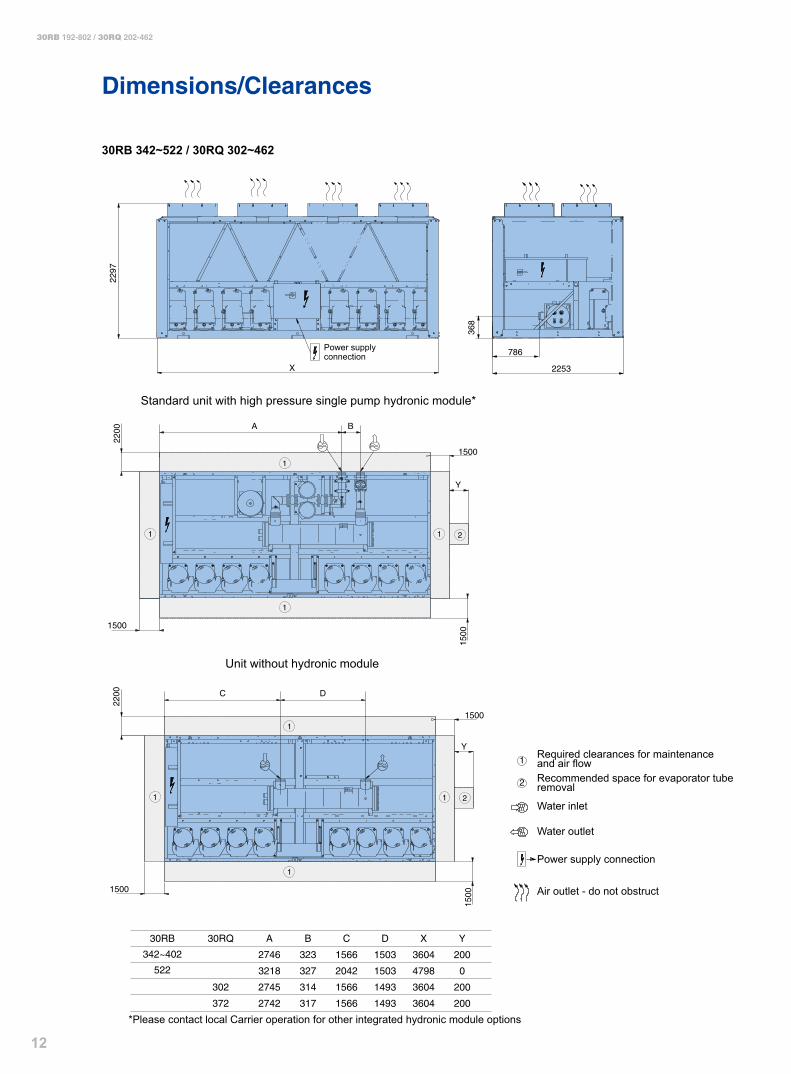
Dimensions/Clearances
30RB 342~522 / 30RQ 302~462
2
1
368
786
2297
1500
2200 A B
1500
2200
150015
00
Y
X
1500
1500
Y
1
1
1
1
2
1
1
1
1
2
C D
2253
30RB
342~402
522
30RQ
302
372
A
2746
3218
2745
2742
B
323
327
314
317
C
1566
2042
1566
1566
D
1503
1503
1493
1493
X
3604
4798
3604
3604
Y
200
0
200
200
432~462 3218 327 2042 1493 4798 0
Power supply connection
Required clearances for maintenanceand air flowRecommended space for evaporator tuberemoval
Water inlet
Water outlet
Power supply connection
Air outlet - do not obstruct
Standard unit with high pressure single pump hydronic module*
Unit without hydronic module
*Please contact local Carrier operation for other integrated hydronic module options
1�
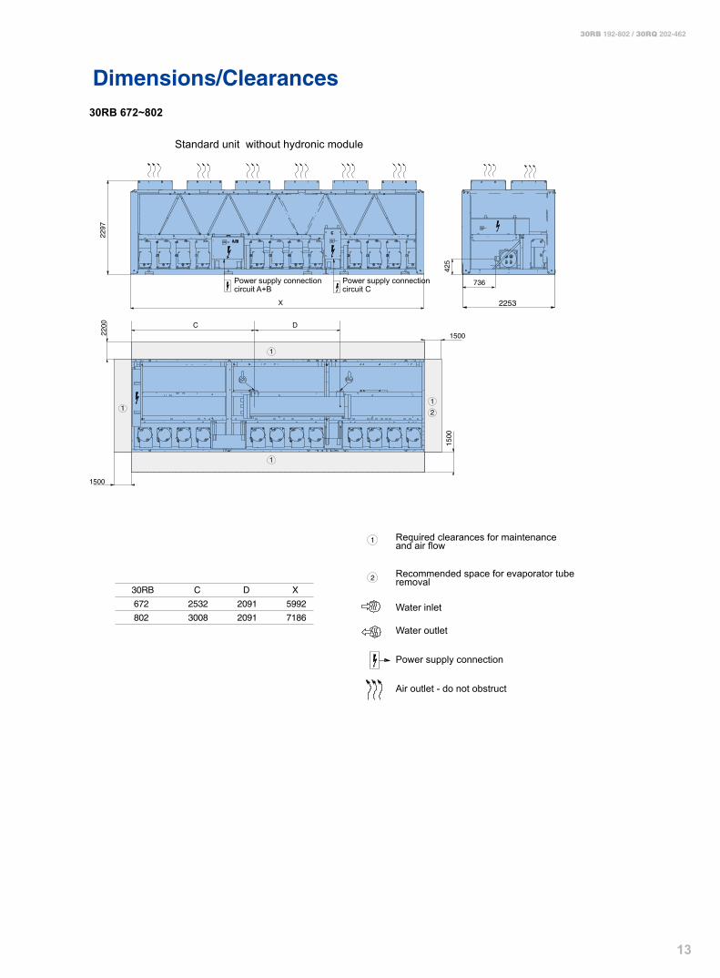
30RB 192-802 / 30RQ 202-462
Dimensions/Clearances30RB 672~802
30RB
672
802
C
2532
3008
D
2091
2091
X
5992
7186
1500
1500
X
1500
2200
2297
1
11
1
2
425
736
C D
2253
2
1
Power supply connection circuit A+B
Power supply connection circuit C
Required clearances for maintenanceand air flow
Recommended space for evaporator tuberemoval
Water inlet
Water outlet
Power supply connection
Air outlet - do not obstruct
Standard unit without hydronic module

1�
30RB 192-802 / 30RQ 202-462
Multiple Chiller Installation
3000
1500
3000
3000
1500
3000
1500
15001500
F
F
5035
0 350
30RB672
F
P7
P8 P10
P9
G446
P3
P4P2
P1
B
D
A
C
P6
P5
E
30RB802
Unit’s footprint
Square hole 100x100
Section F-F
Note: Foot screws M20x300
F
P7
P8
30RB52230RB192~40230RQ202~372 30RQ432~462
446
P3
P4P2
P1
B
DA
C
P6
P5
EE
P5
P6
C
A
D
B
P1
P2 P4
P3
446446
P3
P4P2
P1
B
D
A
C
Weight Distribution
Note: If the height of wall exceeds 2m, please contactlocal Carrier Sales & Service Corporation.
ModelsDimensions (mm) Weight distribution (kg) Operating
weightA B C D E F G P1 P2 P3 P4 P5 P6 P7 P8 P9 P10
30RB192 2231 2157 2388 1496 552 491 676 602 2320
30RB232 2231 2157 2388 1496 503 631 530 666 2330
30RB262 2231 2157 2388 1496 665 544 714 587 2510
30RB342 2231 2157 3582 2690 927 769 888 736 3320
30RB402 2231 2157 3582 2690 955 747 1036 812 3550
30RB522 2231 2157 4776 1942 1942 677 543 1129 857 716 559 4480
30RB672 2231 2157 5970 2690 892 1496 944 744 840 634 840 633 559 445 5640
30RB802 2231 2157 7164 1942 1942 892 1496 519 386 1214 982 681 601 681 681 546 220 6510
30RQ202 2231 2157 2388 1496 579 518 702 628 2425
30RQ232 2231 2157 2388 1496 530 656 556 691 2431
30RQ302 2231 2157 3582 2690 901 755 865 724 3245
30RQ372 2231 2157 3582 2690 953 759 1029 819 3558
30RQ432 2231 2157 4776 1942 1942 648 526 1059 811 683 541 4268
30RQ462 2231 2157 4776 1942 1942 676 549 1106 847 713 565 4454
15
30RB 192-802 / 30RQ 202-462
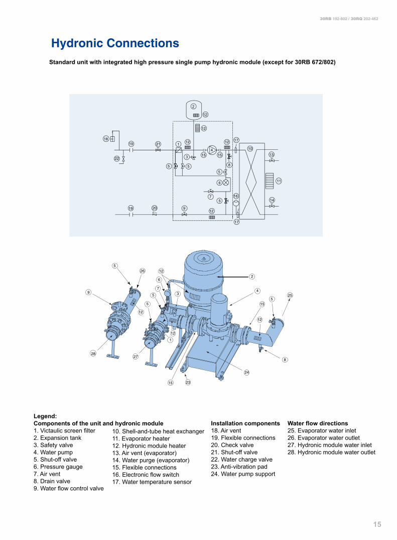
Hydronic ConnectionsStandard unit with integrated high pressure single pump hydronic module (except for 30RB 672/802)
1
2
3
4
5
5
6
7
9
21
19
12
1212
14
131515
16
55 8
18
17
17
12
12
1910
11
20
12
12
5
8
25
15
15
4
2
24
27
23
12
39
265
5
5
7
6
28
12
1
22
Legend:Components of the unit and hydronic module1. Victaulic screen filter2. Expansion tank3. Safety valve4. Water pump5. Shut-off valve6. Pressure gauge7. Air vent8. Drain valve9. Water flow control valve
10. Shell-and-tube heat exchanger11. Evaporator heater12. Hydronic module heater13. Air vent (evaporator)14. Water purge (evaporator)15. Flexible connections16. Electronic flow switch17. Water temperature sensor
Installation components18. Air vent19. Flexible connections20. Check valve21. Shut-off valve22. Water charge valve23. Anti-vibration pad24. Water pump support
Water flow directions25. Evaporator water inlet26. Evaporator water outlet27. Hydronic module water inlet28. Hydronic module water outlet
16
30RB 192-802 / 30RQ 202-462
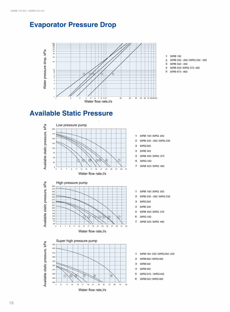
Evaporator Pressure Drop
1 30RB 192 / 30RQ 202
30RB 232 ~ 262 / 30RQ 2322
30RQ 3023
4 30RB 342
5 30RB 402 / 30RQ 372
30RQ 4326
30RB 522 / 30RQ 462 7
30RB 192 / 30RQ 2021
30RB 232 ~ 262 / 30RQ 2322
30RQ 3023
4 30RB 342
30RB 402 / 30RQ 372 5
30RQ 4326
30RB 522 / 30RQ 4627
0
25
50
75
100
125
150
175
200
3 5 7 9 11 13 15 17 19 21 23 25 27 29 31
32 4 5 6 7
1
2
3
4
5
6225
200
250
275
300
325
350
375
400
425
7 9 11 13 15 17 19 21 23 25 27 29 31 33
32 4 5 6
10090807060
50
40
30
20
98
100
10
765
4
3
2
9 2010 30 40 50 60 70 80 902 3 4 5 6 7 81
1
543125
30RB 192
30RB 232 ~ 262 / 30RQ 202 ~ 302
30RB 342 ~ 402
30RB 522 / 30RQ 372~462
30RB 672 ~ 802
2
1
2
4
3
5075
100125150175200225250275300325350375400
3 5 7 9 11 13 15 17 19 21 23 25 27 29 31 33
42 6 753
30RB 192~232 / 30RQ 202~232
30RB 262 / 30RQ 302
30RB 342
30RB 402
30RQ 372 / 30RQ 432
30RB 522 / 30RQ 462
Wat
er p
ress
ure
drop
, kP
a
Available Static Pressure
Avai
labl
e st
atic
pre
ssur
e, k
Pa
Water flow rate,l/s
Water flow rate,l/s
Low pressure pump
Water flow rate,l/s
High pressure pump
Water flow rate,l/s
Super high pressure pump
Avai
labl
e st
atic
pre
ssur
e, k
Pa
Avai
labl
e st
atic
pre
ssur
e, k
Pa
17
30RB 192-802 / 30RQ 202-462
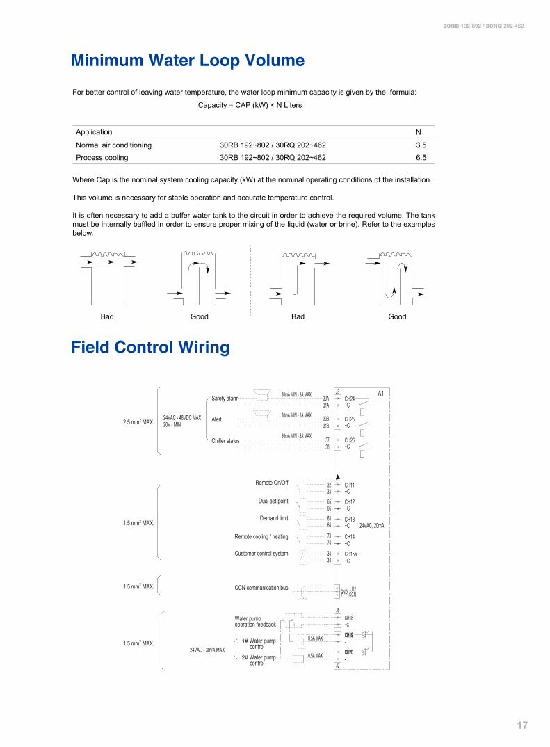
Minimum Water Loop Volume
Field Control Wiring
For better control of leaving water temperature, the water loop minimum capacity is given by the formula:
Capacity = CAP (kW) × N Liters
Application
Normal air conditioning
Process cooling
N
Where Cap is the nominal system cooling capacity (kW) at the nominal operating conditions of the installation.
This volume is necessary for stable operation and accurate temperature control.
It is often necessary to add a buffer water tank to the circuit in order to achieve the required volume. The tank must be internally baffled in order to ensure proper mixing of the liquid (water or brine). Refer to the examples below.
Bad Good Bad Good
3.5
6.5
30RB 192~802 / 30RQ 202~462
30RB 192~802 / 30RQ 202~462
A180mA MIN - 3A MAX
3837
31B30B
31A30A
J3
J4J4J4J4J4J4J4J4J4J4J4J4J4J4J4J4
80mA MIN - 3A MAX
80mA MIN - 3A MAX
20V - MIN24VAC - 48VDC MAX
2.5 mm2 MAX.
+C
CH15a
CH13
323365666364
7374
3435
24VAC, 20mA
CH14+C
+C
CH12+C
CH11+C
CH26+C
CH25+C
CH24+C
CCNGND
+C
J12
J5
+
CH18
1.5 mm2 MAX.
1.5 mm2 MAX.
0.5A MAX
0.5A MAX
CH19CH19-CH20CH20--
J2
1.5 mm2 MAX.24VAC - 30VA MAX
Safety alarm
Remote On/Off
Dual set point
Demand limit
Remote cooling / heating
Customer control system
CCN communication bus
Water pump operation feedback
1# Water pump control 2# Water pump control
Alert
Chiller status

E-30RB/RQ-1007-01-CHK
Carrier Corporation identified six specific areas of concentration that directly impact howwe, as a world manufacturer, balance our curtomer' needs for comfort with the environment'sneeds for responsible consumption.
Welcome to Carrier Websitew w w . c a r r i e r . c o m . c n
The Manufacturer reserves the right to change any produt specifications without notices All Rights Reserved Carrier