february 2008 mv metal-clad...
TRANSCRIPT

© ABB Group January 4, 2015 | Slide 1
MV Metal-Clad SwitchgearThe safest, most reliable Switchgear in the market today
February 2008
© ABB Group January 4, 2015 | Slide 2
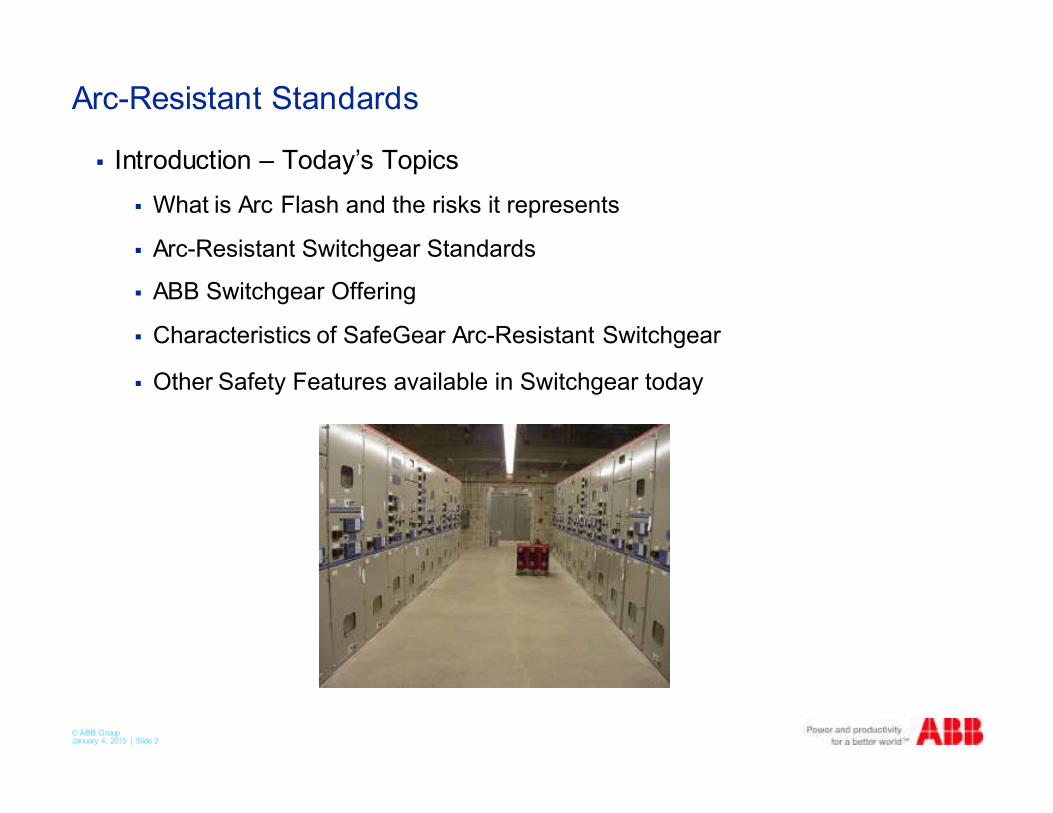
Arc-Resistant Standards
� Introduction – Today’s Topics
� What is Arc Flash and the risks it represents
� Arc-Resistant Switchgear Standards
� ABB Switchgear Offering
� Characteristics of SafeGear Arc-Resistant Switchgear
� Other Safety Features available in Switchgear today

© ABB Group January 4, 2015 | Slide 3
What is an Arc Flash?
� The result of a rapid release
of energy due to an arcing fault
between phases, neutral or a
ground.
�An arc arises when at least part of the current passes through a
dielectric, usually air
� Maximum peak power up to 40 MW
�Arc temperature up to five times the surface temperature of the sun
(20,000°C)
� Light intensity more than 2000 times
that of normal office light
� Volumetric expansion approximately
40,000+ - 1
Temperature of
the sun surface is
about 5000°C.
© ABB Group January 4, 2015 | Slide 4
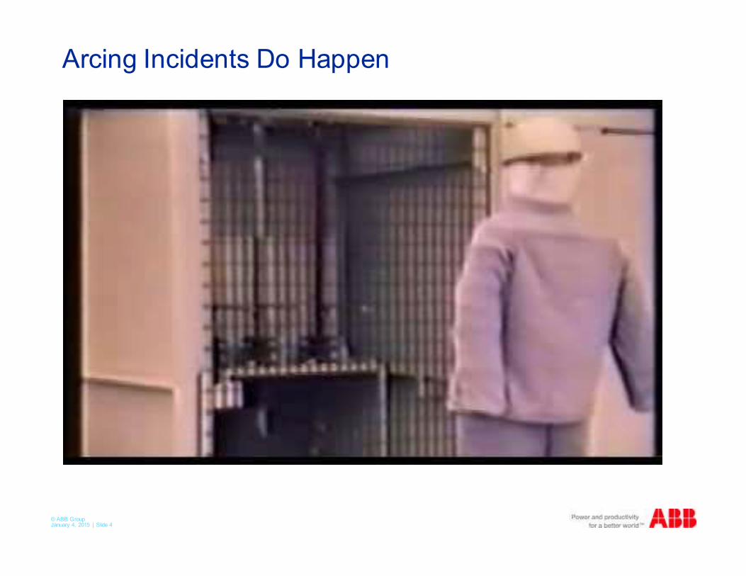
Arcing Incidents Do Happen
Fault characteristics
An arc arises when at least part of the current
passes through a dielectric, usually air
Maximum peak power up to 40 MW
Arc temperature up to five times the surface
temperature of the sun (20 000°C)
Light intensity more than 2000 times that of
normal office light
© ABB Group January 4, 2015 | Slide 5
Arc Flash Danger Statistics
� Currently, OSHA lumps Arc Flash incidents in with electrical incidents.
� A recent survey showed that 5-10 people per day go to burn centers due to arc flash incidents – that does not include those going to local and regional hospitals
� That is 2000-3500 people a year in the US!
� With the high mortality rate of burn injuries, this can translate to hundreds of deaths a year
� IEEE did a study with a large utility and over the last 53 years, they have had 1 arc flash incident every 18 months.
© ABB Group January 4, 2015 | Slide 6
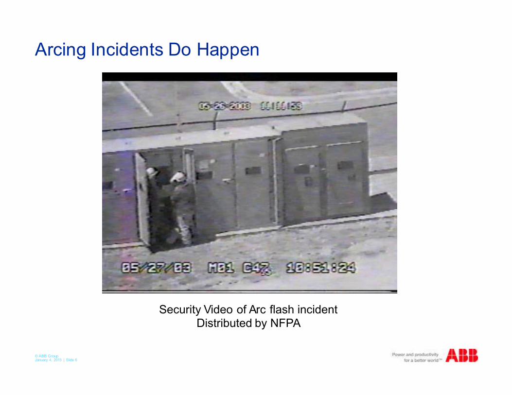
Arcing Incidents Do Happen
Security Video of Arc flash incidentDistributed by NFPA
© ABB Group January 4, 2015 | Slide 7
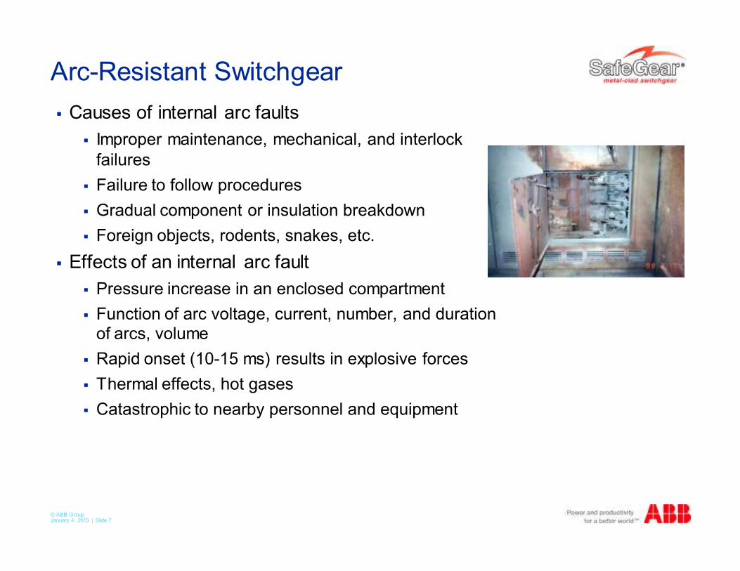
Arc-Resistant Switchgear
� Causes of internal arc faults
� Improper maintenance, mechanical, and interlock
failures
� Failure to follow procedures
� Gradual component or insulation breakdown
� Foreign objects, rodents, snakes, etc.
� Effects of an internal arc fault
� Pressure increase in an enclosed compartment
� Function of arc voltage, current, number, and duration of arcs, volume
� Rapid onset (10-15 ms) results in explosive forces
� Thermal effects, hot gases
� Catastrophic to nearby personnel and equipment
© ABB Group January 4, 2015 | Slide 8
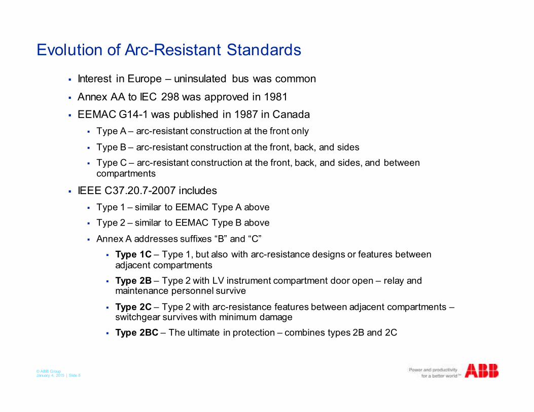
Evolution of Arc-Resistant Standards
� Interest in Europe – uninsulated bus was common
� Annex AA to IEC 298 was approved in 1981
� EEMAC G14-1 was published in 1987 in Canada
� Type A – arc-resistant construction at the front only
� Type B – arc-resistant construction at the front, back, and sides
� Type C – arc-resistant construction at the front, back, and sides, and between compartments
� IEEE C37.20.7-2007 includes
� Type 1 – similar to EEMAC Type A above
� Type 2 – similar to EEMAC Type B above
� Annex A addresses suffixes “B” and “C”
� Type 1C – Type 1, but also with arc-resistance designs or features between adjacent compartments
� Type 2B – Type 2 with LV instrument compartment door open – relay and maintenance personnel survive
� Type 2C – Type 2 with arc-resistance features between adjacent compartments –switchgear survives with minimum damage
� Type 2BC – The ultimate in protection – combines types 2B and 2C
© ABB Group January 4, 2015 | Slide 9
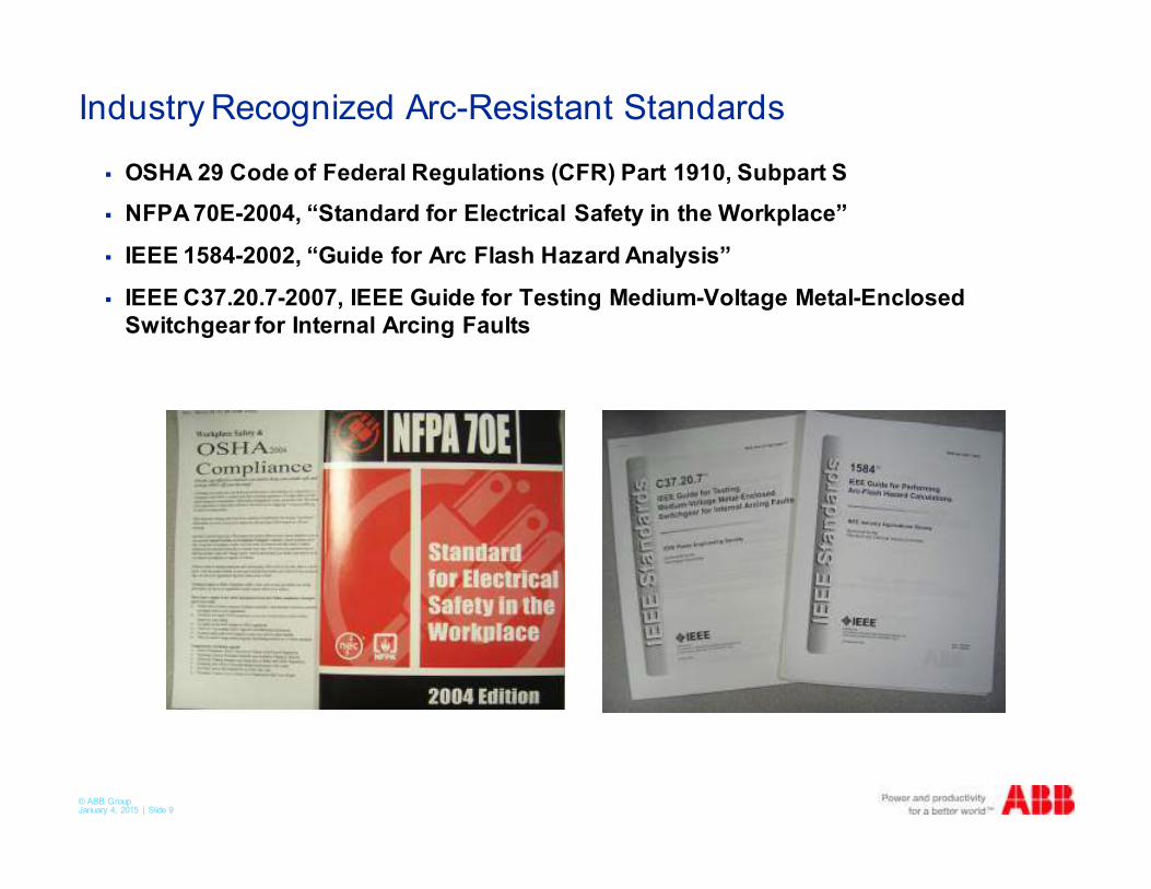
Industry Recognized Arc-Resistant Standards
� OSHA 29 Code of Federal Regulations (CFR) Part 1910, Subpart S
� NFPA 70E-2004, “Standard for Electrical Safety in the Workplace”
� IEEE 1584-2002, “Guide for Arc Flash Hazard Analysis”
� IEEE C37.20.7-2007, IEEE Guide for Testing Medium-Voltage Metal-Enclosed
Switchgear for Internal Arcing Faults
© ABB Group January 4, 2015 | Slide 10
Arc-Resistant Standards
� Current Requirements and How They Apply
� OSHA 29 Code of Federal Regulations (CFR) Part 1910, Subpart S
� Safe practices to prevent electrical shock or burns must be
implemented
� Mandates that exposed workers must be qualified
� Requires provisions for the appropriate personnel protective
equipment (PPE)
� NFPA 70E-2004, “Standard for Electrical Safety in the Workplace”
� Details steps to comply with the OSHA requirements
� Worker training
� Appropriate, safe tools
� Safety program
� Arc flash hazard calculations
� PPE
� Equipment warning labels
© ABB Group January 4, 2015 | Slide 11
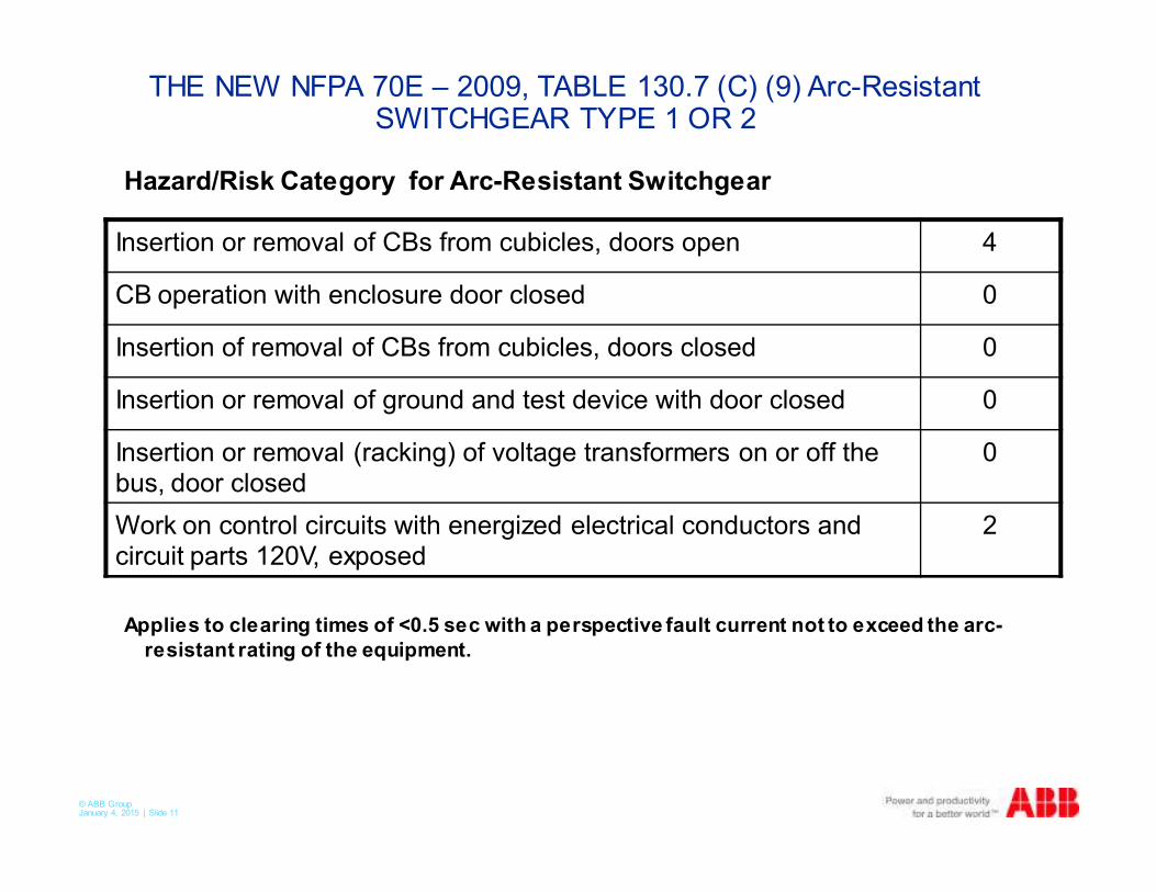
THE NEW NFPA 70E – 2009, TABLE 130.7 (C) (9) Arc-Resistant SWITCHGEAR TYPE 1 OR 2
Hazard/Risk Category for Arc-Resistant Switchgear
Applies to clearing times of <0.5 sec with a perspective fault current not to exceed the arc-
resistant rating of the equipment.
Insertion or removal of CBs from cubicles, doors open 4
CB operation with enclosure door closed 0
Insertion of removal of CBs from cubicles, doors closed 0
Insertion or removal of ground and test device with door closed 0
Insertion or removal (racking) of voltage transformers on or off the bus, door closed
0
Work on control circuits with energized electrical conductors and circuit parts 120V, exposed
2
© ABB Group January 4, 2015 | Slide 12
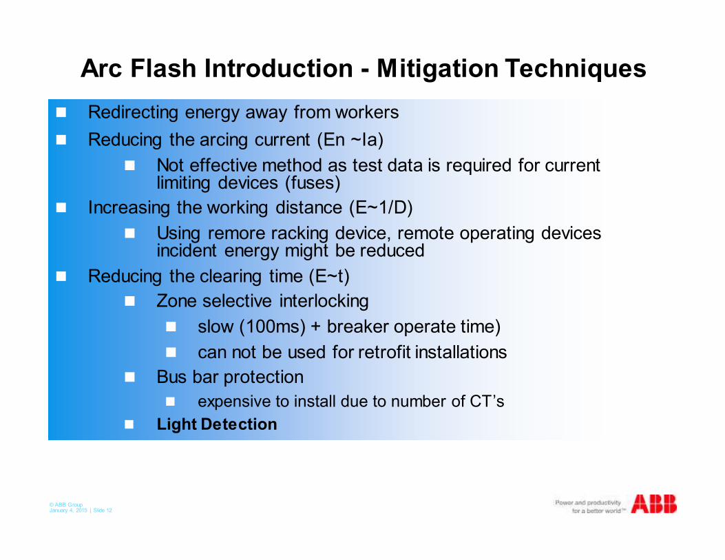
Arc Flash Introduction - Mitigation Techniques
� Redirecting energy away from workers
� Reducing the arcing current (En ~Ia)
� Not effective method as test data is required for current limiting devices (fuses)
� Increasing the working distance (E~1/D)
� Using remore racking device, remote operating devices incident energy might be reduced
� Reducing the clearing time (E~t)
� Zone selective interlocking
� slow (100ms) + breaker operate time)
� can not be used for retrofit installations
� Bus bar protection
� expensive to install due to number of CT’s
� Light Detection
© ABB Group January 4, 2015 | Slide 13
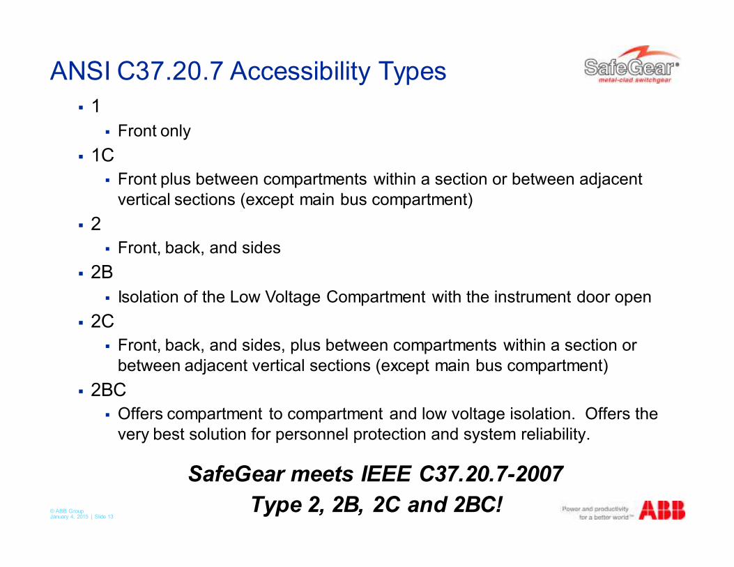
ANSI C37.20.7 Accessibility Types
� 1
� Front only
� 1C
� Front plus between compartments within a section or between adjacent
vertical sections (except main bus compartment)
� 2
� Front, back, and sides
� 2B
� Isolation of the Low Voltage Compartment with the instrument door open
� 2C
� Front, back, and sides, plus between compartments within a section or
between adjacent vertical sections (except main bus compartment)
� 2BC
� Offers compartment to compartment and low voltage isolation. Offers the
very best solution for personnel protection and system reliability.
SafeGear meets IEEE C37.20.7-2007
Type 2, 2B, 2C and 2BC!
© ABB Group January 4, 2015 | Slide 14
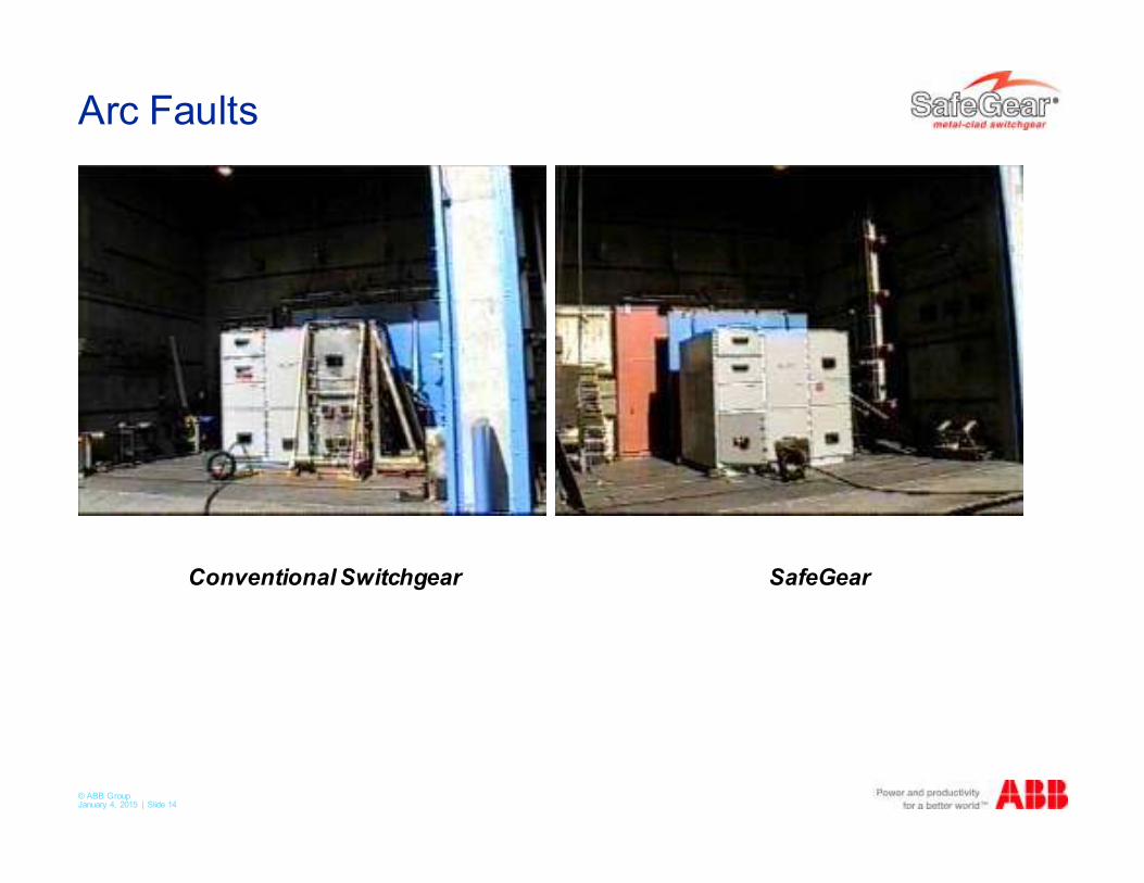
Arc Faults
SafeGearConventional Switchgear
© ABB Group January 4, 2015 | Slide 15
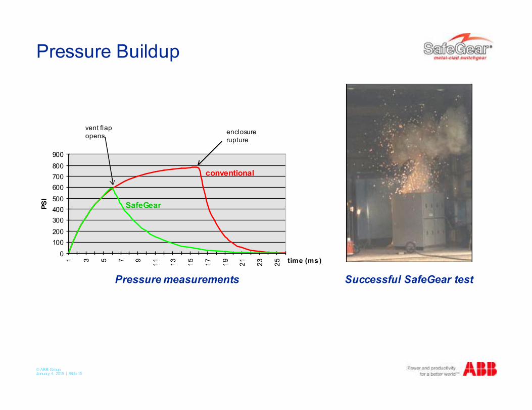
Pressure Buildup
0
100
200
300
400
500
600
700
800
900
1 3 5 7 9
11
13
15
17
19
21
23
25 time (ms)
PS
I
enclosure
rupture
Pressure measurements
vent flap
opens
Successful SafeGear test
SafeGear
conventional
© ABB Group January 4, 2015 | Slide 16
Introduction to ABB ANSI Switchgear
� 5 to 15 kV metal clad switchgear
� Advance
� Traditional non-arc-resistant switchgear
� SafeGear
� Meets ANSI Standard C37.20.7-2007 for arc-resistance
� Four versions – Types 2, 2B, 2C and 2BC available
� Vacuum circuit breakers
� AMVAC
� Magnetically actuated mechanism
� ADVAC
� Spring operated mechanism
© ABB Group January 4, 2015 | Slide 17
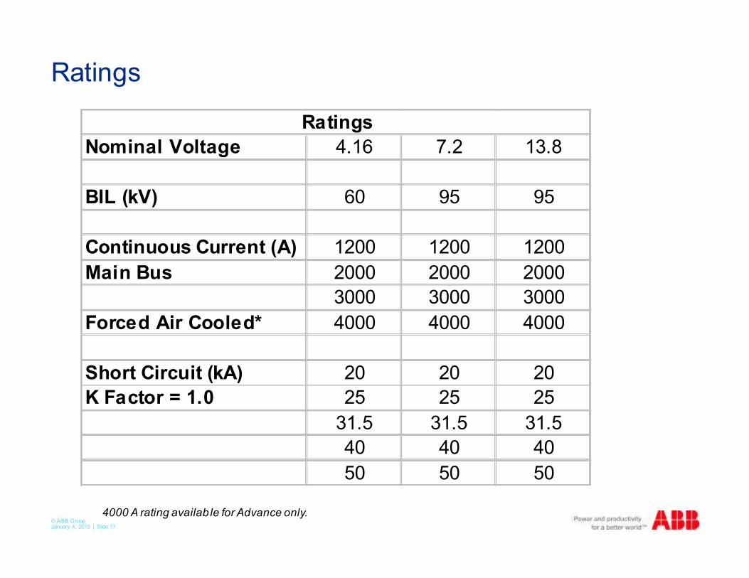
Ratings
Nominal Voltage 4.16 7.2 13.8
BIL (kV) 60 95 95
Continuous Current (A) 1200 1200 1200
Main Bus 2000 2000 2000
3000 3000 3000
Forced Air Cooled* 4000 4000 4000
Short Circuit (kA) 20 20 20
K Factor = 1.0 25 25 25
31.5 31.5 31.5
40 40 40
50 50 50
Ratings
4000 A rating availab le for Advance only.
© ABB Group January 4, 2015 | Slide 18
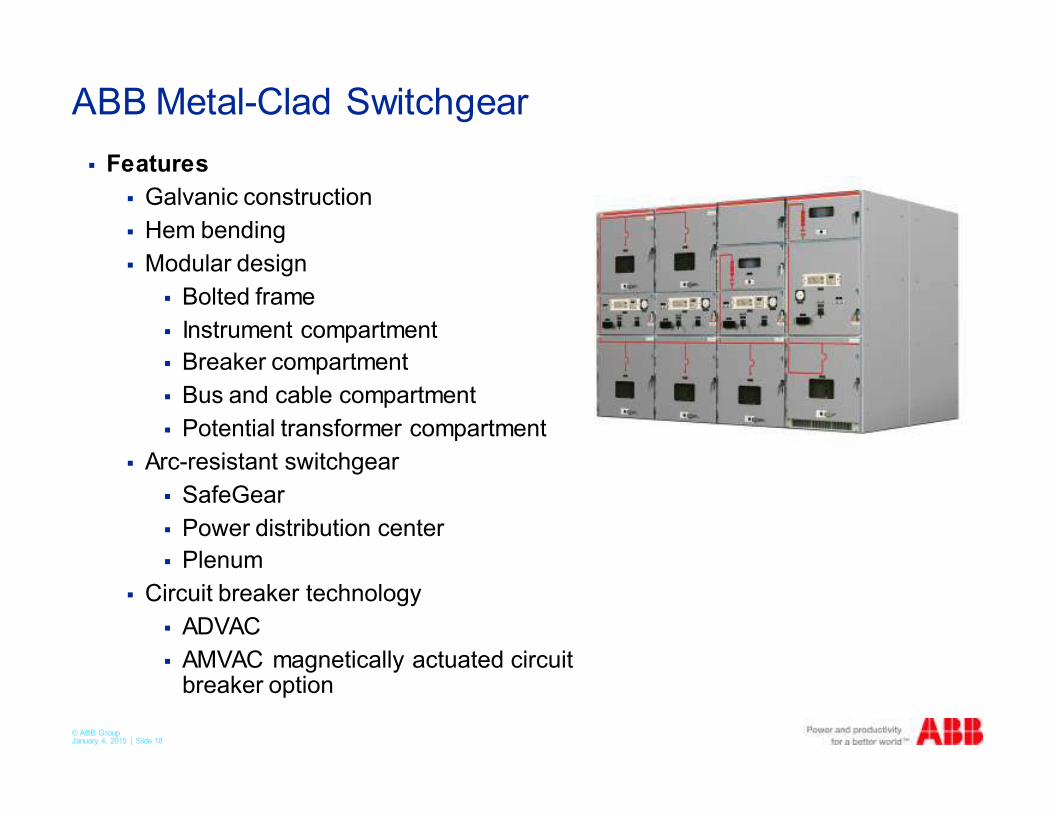
ABB Metal-Clad Switchgear
� Features
� Galvanic construction
� Hem bending
� Modular design
� Bolted frame
� Instrument compartment
� Breaker compartment
� Bus and cable compartment
� Potential transformer compartment
� Arc-resistant switchgear
� SafeGear
� Power distribution center
� Plenum
� Circuit breaker technology
� ADVAC
� AMVAC magnetically actuated circuit breaker option
© ABB Group January 4, 2015 | Slide 19
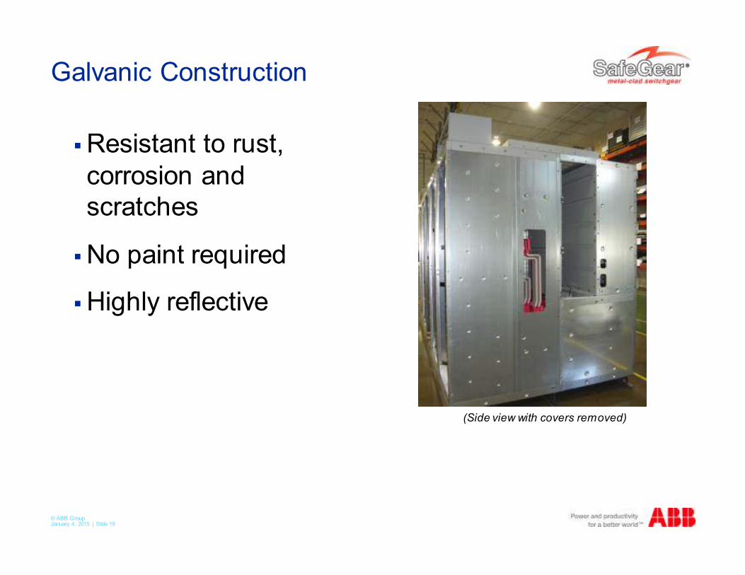
Galvanic Construction
�Resistant to rust,
corrosion and
scratches
�No paint required
�Highly reflective
(Side view with covers removed)
© ABB Group January 4, 2015 | Slide 20
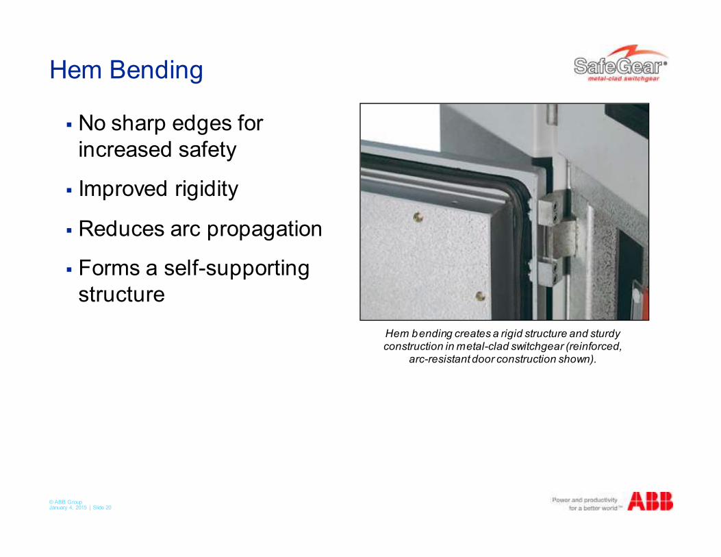
Hem Bending
� No sharp edges for
increased safety
� Improved rigidity
� Reduces arc propagation
� Forms a self-supporting
structure
Hem bending creates a rigid structure and sturdyconstruction in metal-clad switchgear (reinforced,
arc-resistant door construction shown).
© ABB Group January 4, 2015 | Slide 21
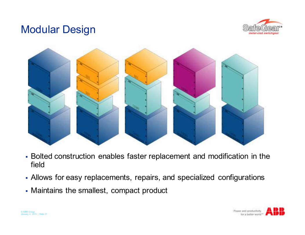
Modular Design
� Bolted construction enables faster replacement and modification in the field
� Allows for easy replacements, repairs, and specialized configurations
� Maintains the smallest, compact product
© ABB Group January 4, 2015 | Slide 22
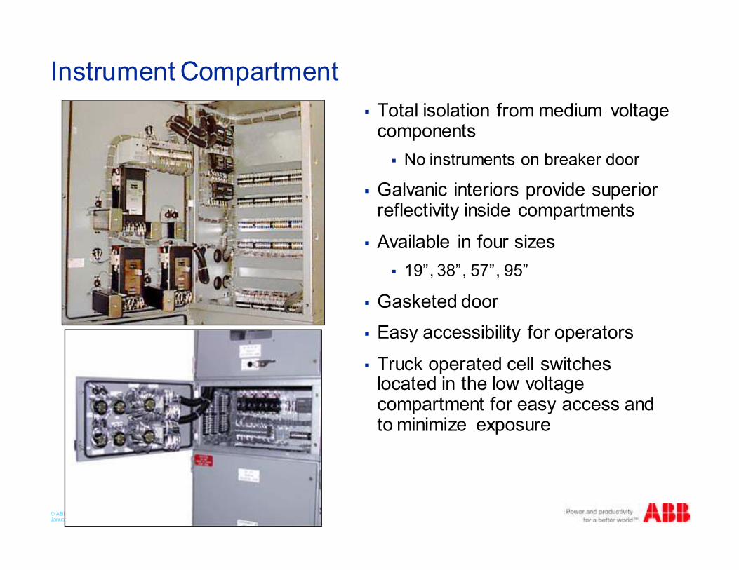
Instrument Compartment
� Total isolation from medium voltage components
� No instruments on breaker door
� Galvanic interiors provide superior reflectivity inside compartments
� Available in four sizes
� 19”, 38”, 57”, 95”
� Gasketed door
� Easy accessibility for operators
� Truck operated cell switches located in the low voltage compartment for easy access and to minimize exposure
© ABB Group January 4, 2015 | Slide 23
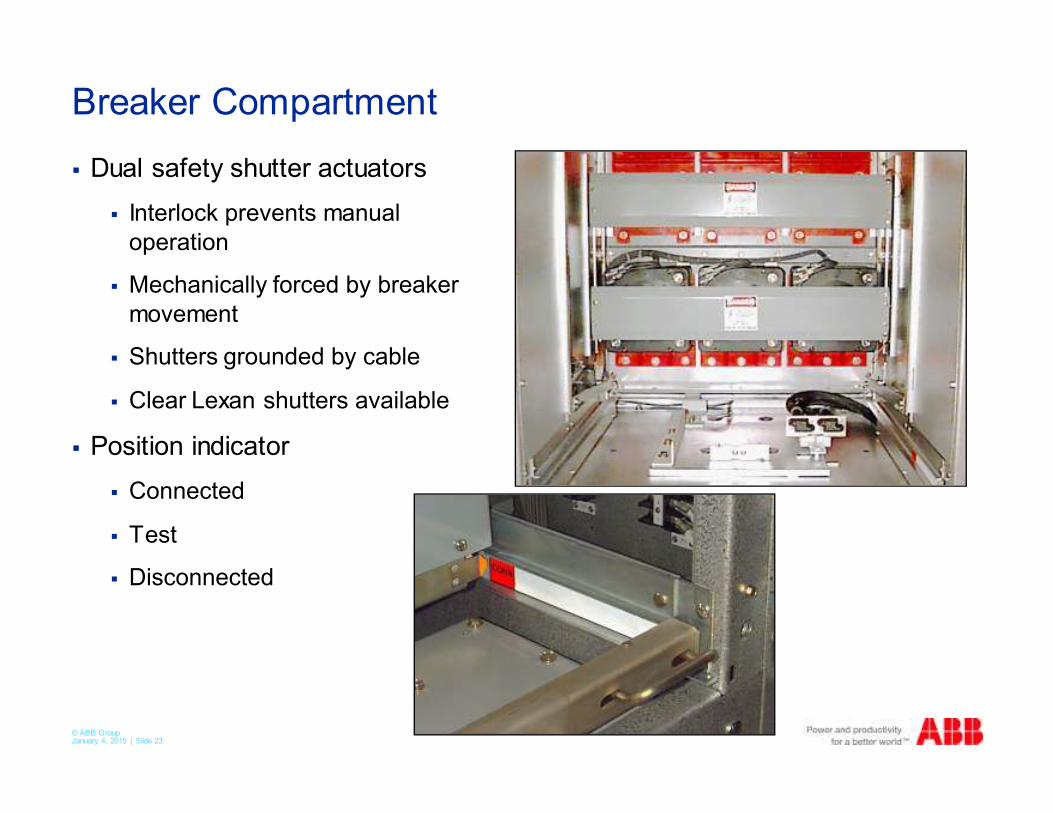
Breaker Compartment
� Dual safety shutter actuators
� Interlock prevents manual
operation
� Mechanically forced by breaker
movement
� Shutters grounded by cable
� Clear Lexan shutters available
� Position indicator
� Connected
� Test
� Disconnected

© ABB Group January 4, 2015 | Slide 24
Breaker Compartment
� Automatic secondary
disconnect
� Provides improved safety for
workers while operating the
breakers when using SafeGear
� Single or double plug
secondary contacts
� Grounding contact
� Interference block
� Prevents installing undersized breakers
© ABB Group January 4, 2015 | Slide 25
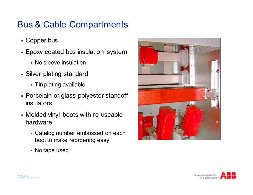
Bus & Cable Compartments
� Copper bus
� Epoxy coated bus insulation system
� No sleeve insulation
� Silver plating standard
� Tin plating available
� Porcelain or glass polyester standoff
insulators
� Molded vinyl boots with re-useable
hardware
� Catalog number embossed on each
boot to make reordering easy
� No tape used
© ABB Group January 4, 2015 | Slide 26
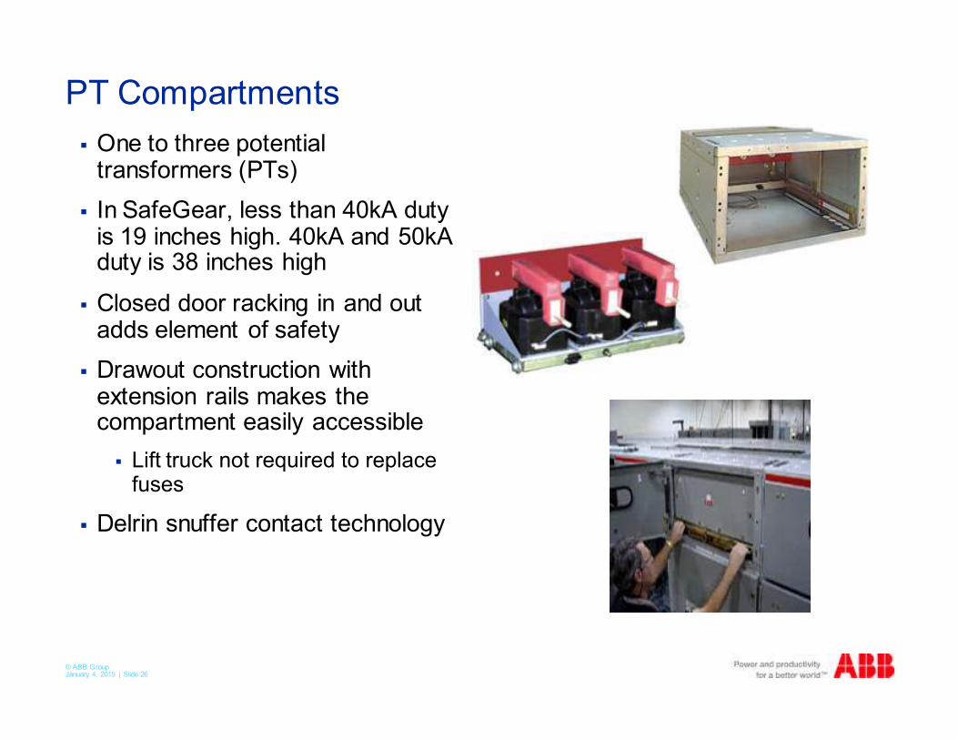
PT Compartments
� One to three potential transformers (PTs)
� In SafeGear, less than 40kA duty is 19 inches high. 40kA and 50kA duty is 38 inches high
� Closed door racking in and out adds element of safety
� Drawout construction with extension rails makes the compartment easily accessible
� Lift truck not required to replace fuses
� Delrin snuffer contact technology
© ABB Group January 4, 2015 | Slide 27
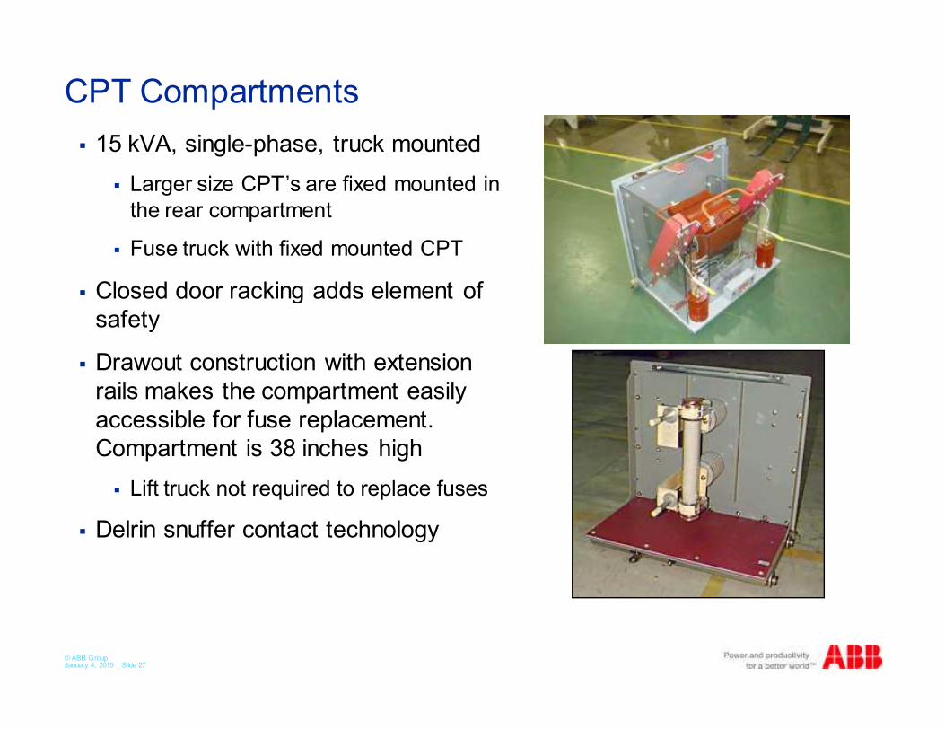
CPT Compartments
� 15 kVA, single-phase, truck mounted
� Larger size CPT’s are fixed mounted in
the rear compartment
� Fuse truck with fixed mounted CPT
� Closed door racking adds element of
safety
� Drawout construction with extension
rails makes the compartment easily
accessible for fuse replacement.
Compartment is 38 inches high
� Lift truck not required to replace fuses
� Delrin snuffer contact technology
© ABB Group January 4, 2015 | Slide 28
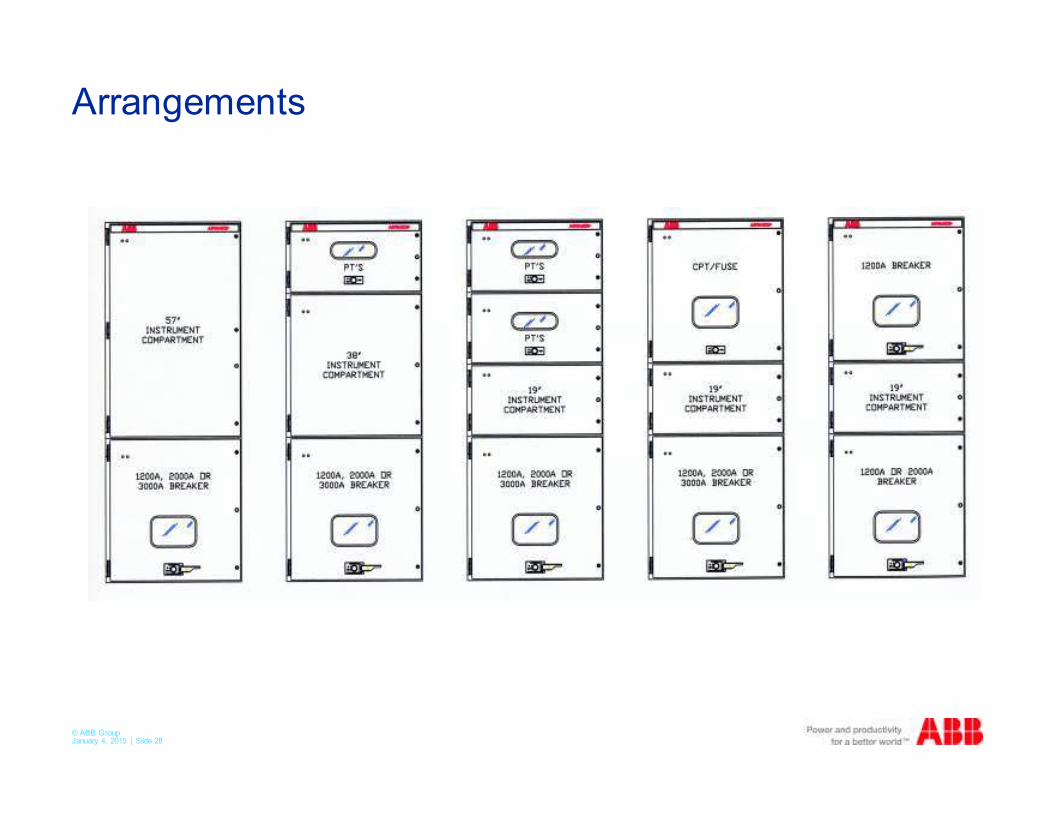
Arrangements
© ABB Group January 4, 2015 | Slide 29
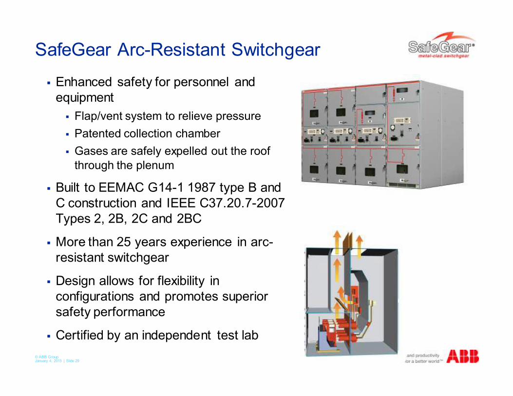
SafeGear Arc-Resistant Switchgear
� Enhanced safety for personnel and
equipment
� Flap/vent system to relieve pressure
� Patented collection chamber
� Gases are safely expelled out the roof
through the plenum
� Built to EEMAC G14-1 1987 type B and
C construction and IEEE C37.20.7-2007
Types 2, 2B, 2C and 2BC
� More than 25 years experience in arc-
resistant switchgear
� Design allows for flexibility in
configurations and promotes superior
safety performance
� Certified by an independent test lab
© ABB Group January 4, 2015 | Slide 30
SafeGear Demonstration
© ABB Group January 4, 2015 | Slide 31
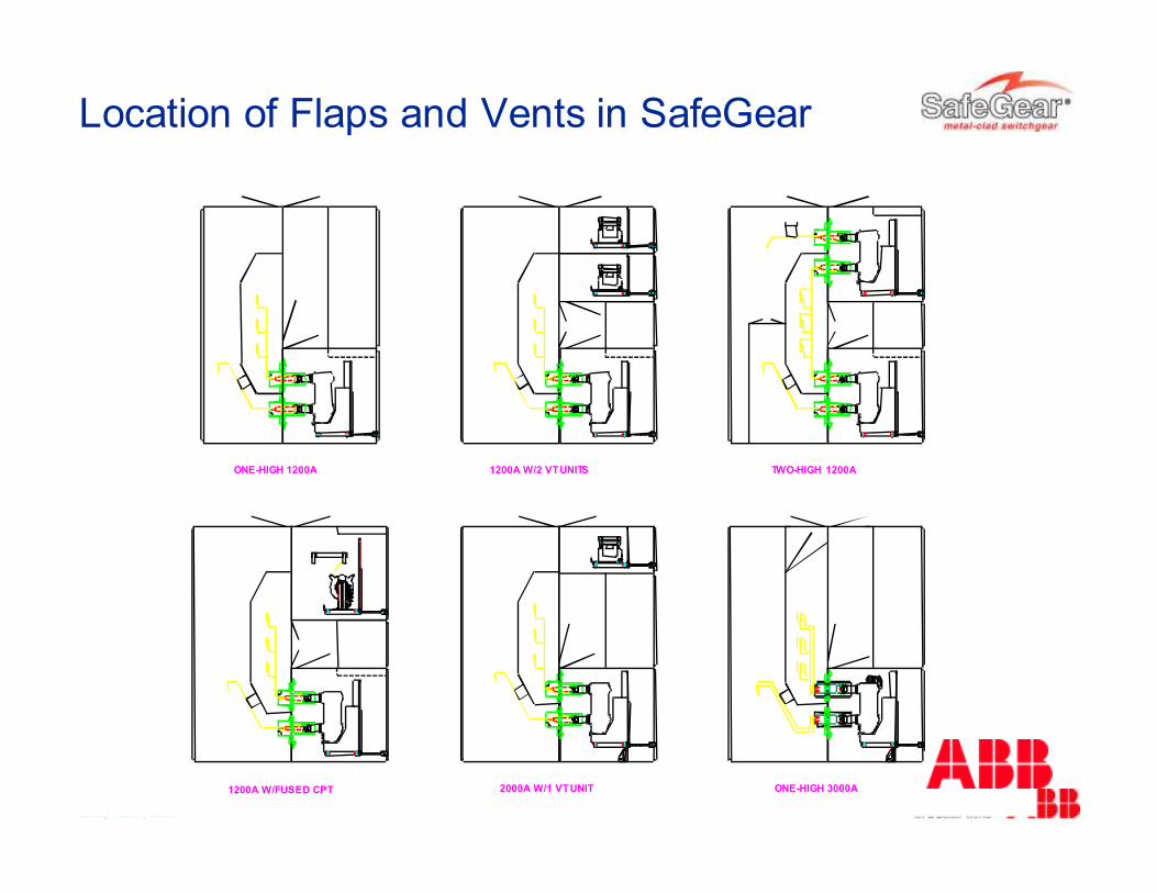
ONE-HIGH 1200A 1200A W/2 VT UNITS TWO-HIGH 1200A
1200A W/FUSED CPT 2000A W/1 VT UNIT ONE-HIGH 3000A
Location of Flaps and Vents in SafeGear
© ABB Group January 4, 2015 | Slide 32
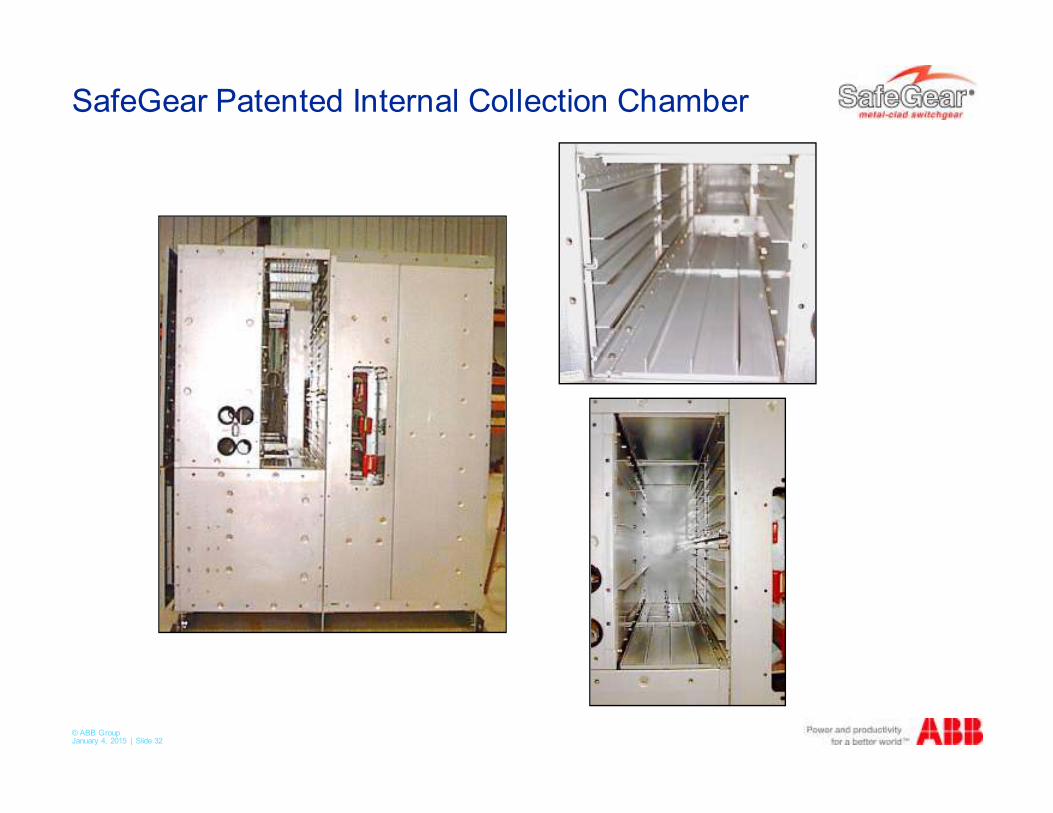
SafeGear Patented Internal Collection Chamber
© ABB Group January 4, 2015 | Slide 33
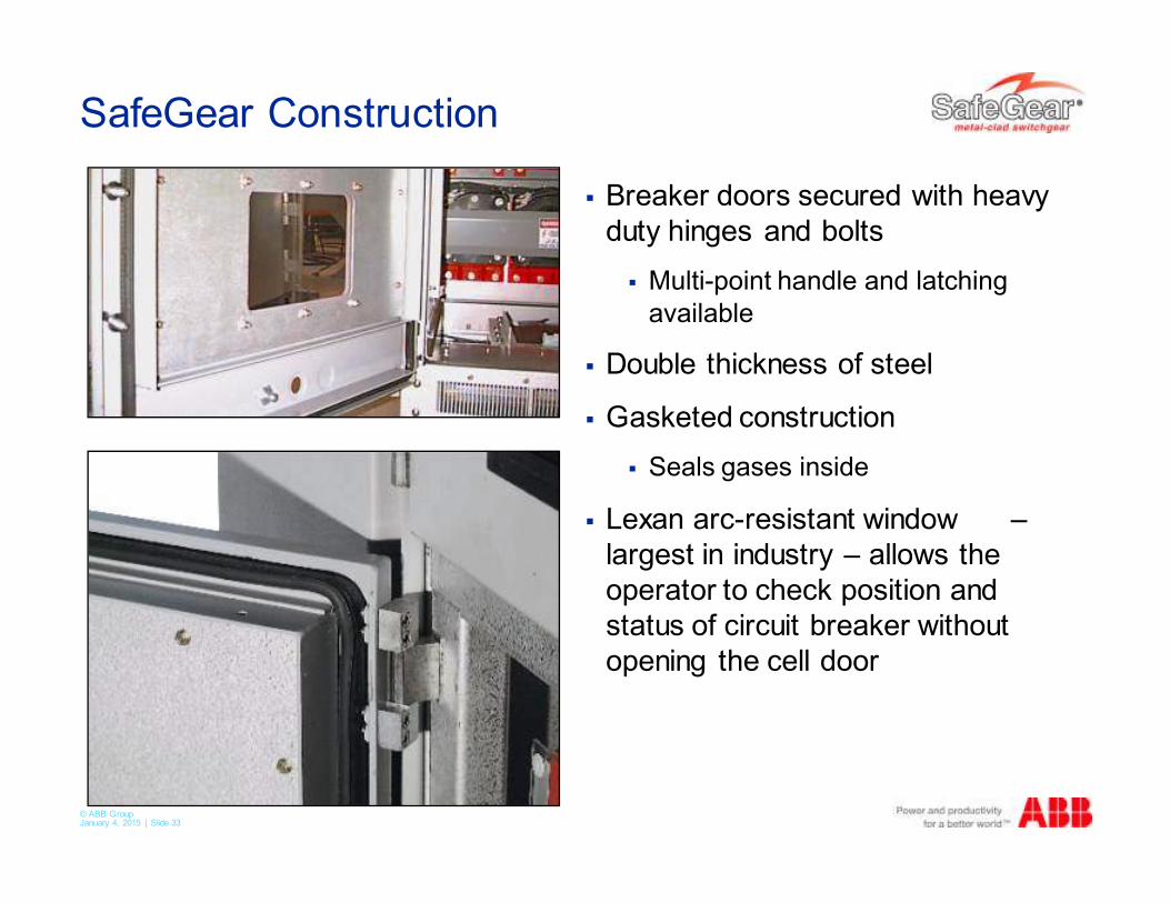
SafeGear Construction
� Breaker doors secured with heavy
duty hinges and bolts
� Multi-point handle and latching
available
� Double thickness of steel
� Gasketed construction
� Seals gases inside
� Lexan arc-resistant window –
largest in industry – allows the
operator to check position and
status of circuit breaker without
opening the cell door
© ABB Group January 4, 2015 | Slide 34
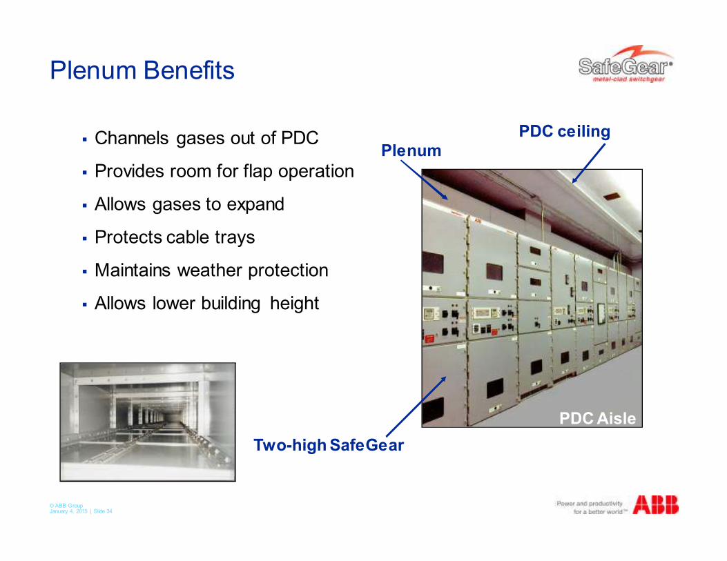
Plenum Benefits
� Channels gases out of PDC
� Provides room for flap operation
� Allows gases to expand
� Protects cable trays
� Maintains weather protection
� Allows lower building height
PlenumPDC ceiling
PDC Aisle
Two-high SafeGear
© ABB Group January 4, 2015 | Slide 35
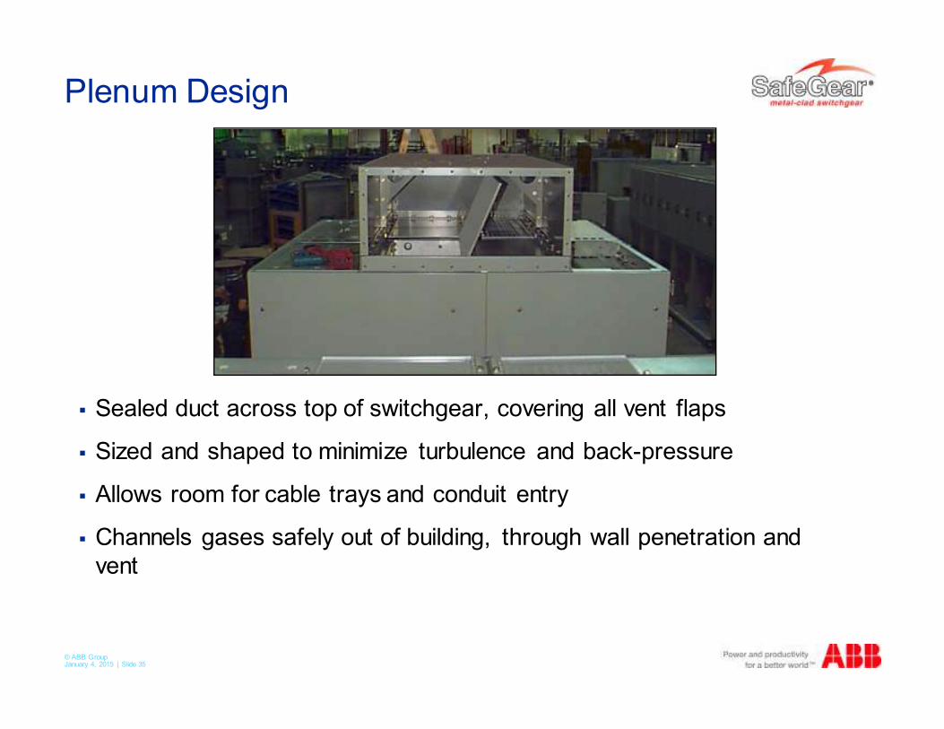
Plenum Design
� Sealed duct across top of switchgear, covering all vent flaps
� Sized and shaped to minimize turbulence and back-pressure
� Allows room for cable trays and conduit entry
� Channels gases safely out of building, through wall penetration and
vent
© ABB Group January 4, 2015 | Slide 36
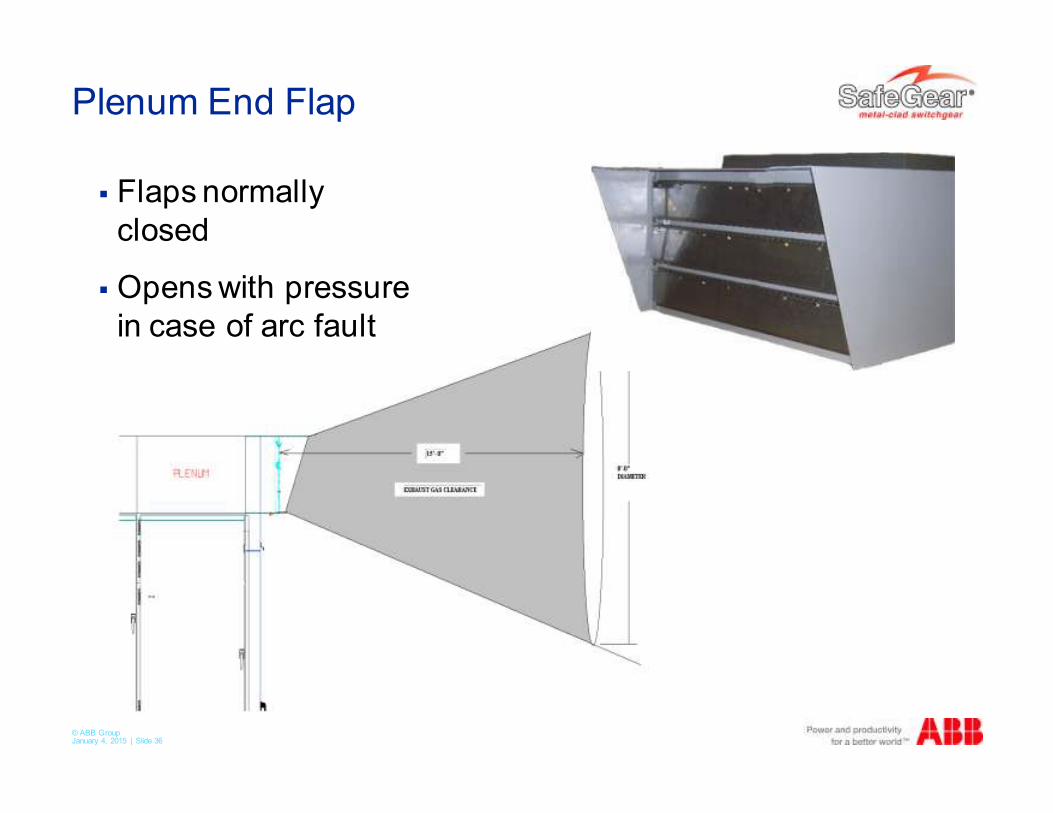
Plenum End Flap
� Flaps normally
closed
� Opens with pressure
in case of arc fault
© ABB Group January 4, 2015 | Slide 37
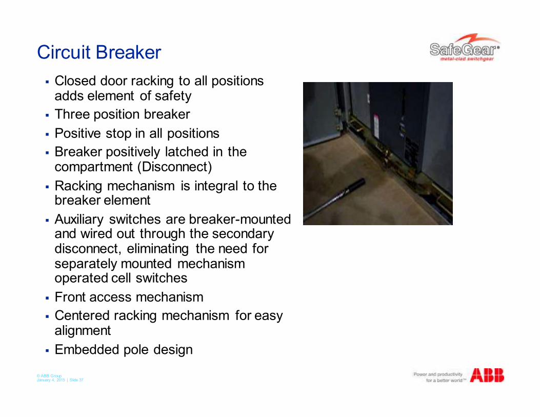
Circuit Breaker
� Closed door racking to all positions adds element of safety
� Three position breaker
� Positive stop in all positions
� Breaker positively latched in the compartment (Disconnect)
� Racking mechanism is integral to the breaker element
� Auxiliary switches are breaker-mounted and wired out through the secondary disconnect, eliminating the need for separately mounted mechanism operated cell switches
� Front access mechanism
� Centered racking mechanism for easy alignment
� Embedded pole design
© ABB Group January 4, 2015 | Slide 38
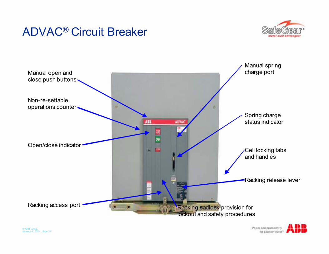
ADVAC® Circuit Breaker
Manual open andclose push buttons
Non-re-settableoperations counter
Open/close indicator
Racking access port
Manual springcharge port
Spring chargestatus indicator
Cell locking tabsand handles
Racking release lever
Racking padlock provision forlockout and safety procedures
© ABB Group January 4, 2015 | Slide 39
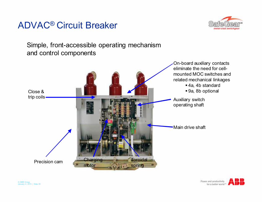
ADVAC® Circuit Breaker
Precision cam
On-board auxiliary contactseliminate the need for cell-
mounted MOC switches and
related mechanical linkages
� 4a, 4b standard
� 9a, 8b optional
Auxiliary switchoperating shaft
Main drive shaft
Charging
motor
Toroidal
spring
Close &trip coils
Simple, front-accessible operating mechanism
and control components
© ABB Group January 4, 2015 | Slide 40
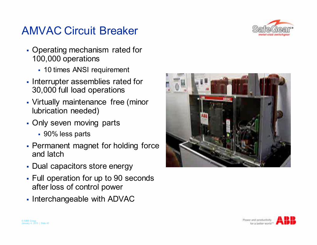
AMVAC Circuit Breaker
� Operating mechanism rated for 100,000 operations
� 10 times ANSI requirement
� Interrupter assemblies rated for 30,000 full load operations
� Virtually maintenance free (minor lubrication needed)
� Only seven moving parts
� 90% less parts
� Permanent magnet for holding force and latch
� Dual capacitors store energy
� Full operation for up to 90 seconds after loss of control power
� Interchangeable with ADVAC
© ABB Group January 4, 2015 | Slide 41
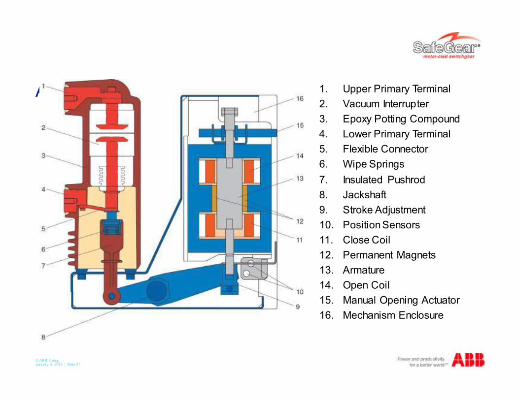
AMVAC Circuit Breaker 1. Upper Primary Terminal
2. Vacuum Interrupter
3. Epoxy Potting Compound
4. Lower Primary Terminal
5. Flexible Connector
6. Wipe Springs
7. Insulated Pushrod
8. Jackshaft
9. Stroke Adjustment
10. Position Sensors
11. Close Coil
12. Permanent Magnets
13. Armature
14. Open Coil
15. Manual Opening Actuator
16. Mechanism Enclosure
© ABB Group January 4, 2015 | Slide 42
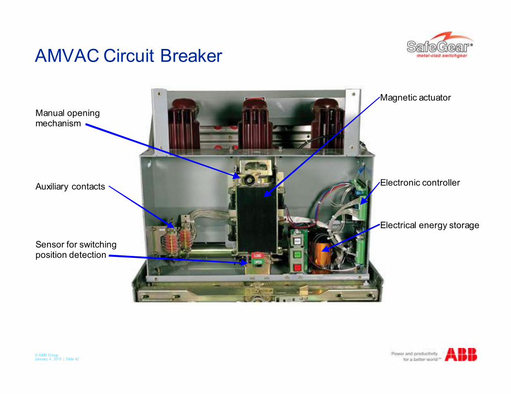
AMVAC Circuit Breaker
Manual opening mechanism
Auxiliary contacts
Sensor for switching position detection
Magnetic actuator
Electronic controller
Electrical energy storage
© ABB Group January 4, 2015 | Slide 43
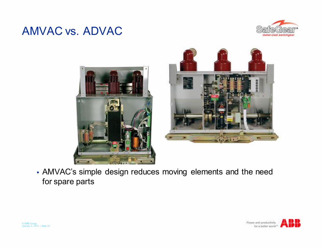
AMVAC vs. ADVAC
� AMVAC’s simple design reduces moving elements and the need
for spare parts
© ABB Group January 4, 2015 | Slide 44
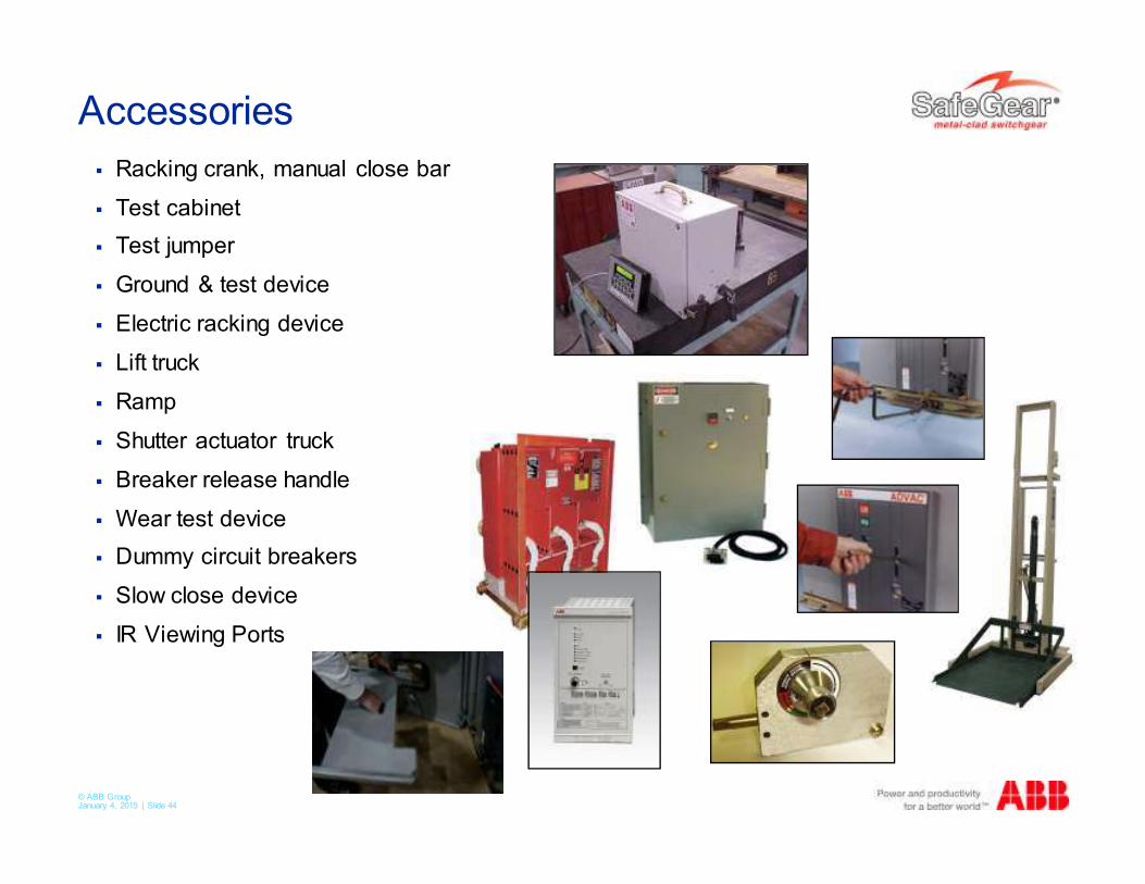
Accessories
� Racking crank, manual close bar
� Test cabinet
� Test jumper
� Ground & test device
� Electric racking device
� Lift truck
� Ramp
� Shutter actuator truck
� Breaker release handle
� Wear test device
� Dummy circuit breakers
� Slow close device
� IR Viewing Ports
© ABB Group January 4, 2015 | Slide 45
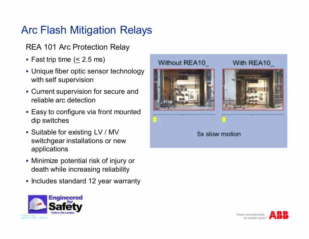
Arc Flash Mitigation Relays
REA 101 Arc Protection Relay
� Fast trip time (< 2.5 ms)
� Unique fiber optic sensor technology
with self supervision
� Current supervision for secure and
reliable arc detection
� Easy to configure via front mounted
dip switches
� Suitable for existing LV / MV
switchgear installations or new applications
� Minimize potential risk of injury or
death while increasing reliability
� Includes standard 12 year warranty
© ABB Group January 4, 2015 | Slide 46
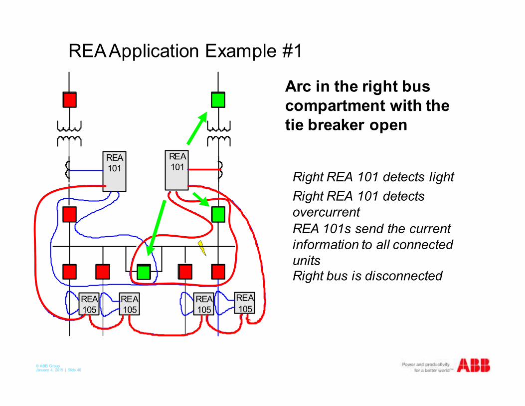
Arc in the right bus
compartment with the
tie breaker open
Right REA 101 detects
overcurrent
Right REA 101 detects light
REA 101s send the current
information to all connected
unitsRight bus is disconnected
REA Application Example #1
REA
101
REA
101
REA
105REA
105
REA
105
REA
105
© ABB Group January 4, 2015 | Slide 47
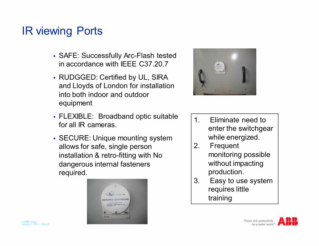
IR viewing Ports
� SAFE: Successfully Arc-Flash tested in accordance with IEEE C37.20.7
� RUDGGED: Certified by UL, SIRA and Lloyds of London for installation
into both indoor and outdoor equipment
� FLEXIBLE: Broadband optic suitable for all IR cameras.
� SECURE: Unique mounting system allows for safe, single person
installation & retro-fitting with No
dangerous internal fasteners required.
1. Eliminate need to enter the switchgear
while energized.2. Frequent
monitoring possible
without impacting production.
3. Easy to use system requires little
training
© ABB Group January 4, 2015 | Slide 48
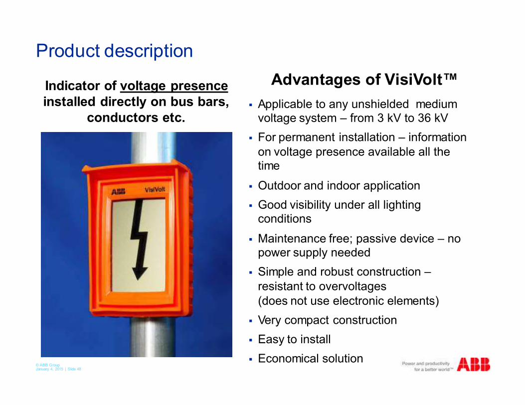
Product description
� Applicable to any unshielded medium voltage system – from 3 kV to 36 kV
� For permanent installation – information
on voltage presence available all the time
� Outdoor and indoor application
� Good visibility under all lighting conditions
� Maintenance free; passive device – no power supply needed
� Simple and robust construction –
resistant to overvoltages
(does not use electronic elements)
� Very compact construction
� Easy to install
� Economical solution
Indicator of voltage presence
installed directly on bus bars,
conductors etc.
Advantages of VisiVolt™
© ABB Group January 4, 2015 | Slide 49
In Summary
� Advance & SafeGear available at 5 and 15kV
� SafeGear arc-resistant switchgear – Types 2, 2B, 2C and 2BC –
provide the highest level of personnel protection
� AMVAC breaker
� 100,000 mechanical operations mechanism
� 30,000 load break operations interrupter
� Virtually maintenance free
� REA Relays
� Protects you personnel and equipment with the most advanced arc
flash mitigation relays on the market.

© ABB Group January 4, 2015 | Slide 50
���