february www .chemengonline.com steam generators · il- and gas-fired package steam generators (or...
TRANSCRIPT

www.chemengonline.com
STEAM
GEN
ERATO
RS • MA
TERIALS SELEC
TION
FOR M
AC
HIN
ING
PROC
ESSES V
OL. 123 N
O. 2 FEBRUA
RY 2016
02 Steam Generators:
Standing up to Superheater Problems
February 2016
Materials Selection for Machining Processes
Advances in Paints and Coatings
Improvements in Seals and Gaskets
Managing Small- and Medium-Sized Projects
Facts at Your Fingertips: Weighing Equipment
Focus on Software and Mobile Apps
page 38
CHEMICAL ENGINEERING WWW.CHEMENGONLINE.COM FEBRUARY 201638
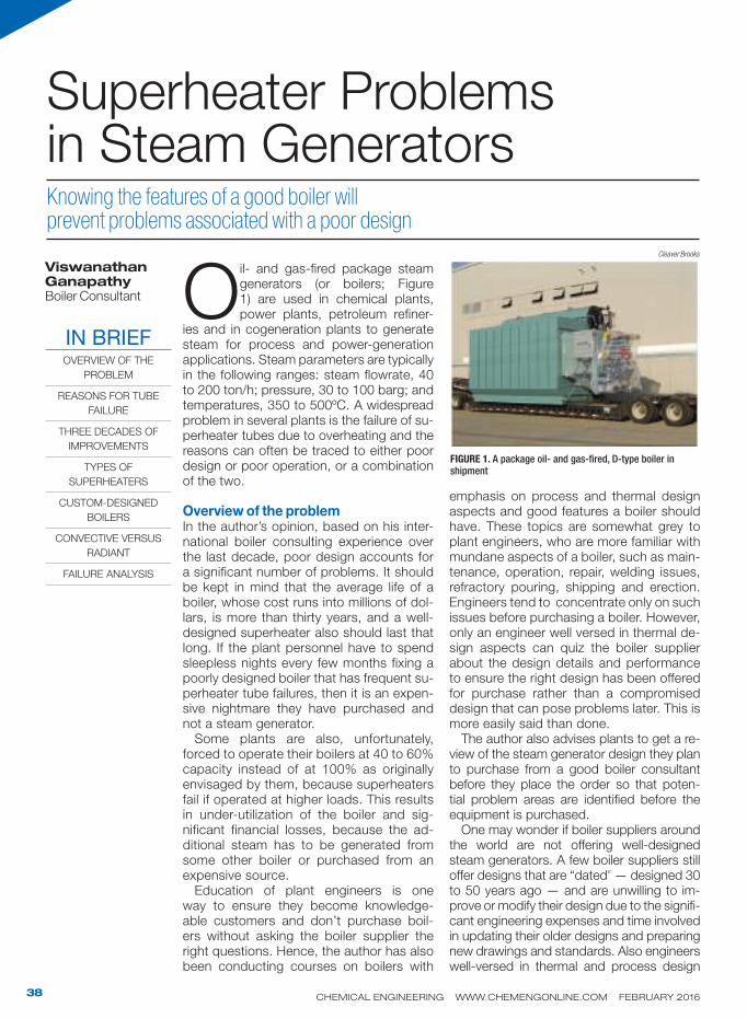
Oil- and gas-fired package steam generators (or boilers; Figure 1) are used in chemical plants, power plants, petroleum refiner-
ies and in cogeneration plants to generate steam for process and power-generation applications. Steam parameters are typically in the following ranges: steam flowrate, 40 to 200 ton/h; pressure, 30 to 100 barg; and temperatures, 350 to 500ºC. A widespread problem in several plants is the failure of su-perheater tubes due to overheating and the reasons can often be traced to either poor design or poor operation, or a combination of the two.
Overview of the problemIn the author’s opinion, based on his inter-national boiler consulting experience over the last decade, poor design accounts for a significant number of problems. It should be kept in mind that the average life of a boiler, whose cost runs into millions of dol-lars, is more than thirty years, and a well-designed superheater also should last that long. If the plant personnel have to spend sleepless nights every few months fixing a poorly designed boiler that has frequent su-perheater tube failures, then it is an expen-sive nightmare they have purchased and not a steam generator.
Some plants are also, unfortunately, forced to operate their boilers at 40 to 60% capacity instead of at 100% as originally envisaged by them, because superheaters fail if operated at higher loads. This results in under-utilization of the boiler and sig-nificant financial losses, because the ad-ditional steam has to be generated from some other boiler or purchased from an expensive source.
Education of plant engineers is one way to ensure they become knowledge-able customers and don’t purchase boil-ers without asking the boiler supplier the right questions. Hence, the author has also been conducting courses on boilers with
emphasis on process and thermal design aspects and good features a boiler should have. These topics are somewhat grey to plant engineers, who are more familiar with mundane aspects of a boiler, such as main-tenance, operation, repair, welding issues, refractory pouring, shipping and erection. Engineers tend to concentrate only on such issues before purchasing a boiler. However, only an engineer well versed in thermal de-sign aspects can quiz the boiler supplier about the design details and performance to ensure the right design has been offered for purchase rather than a compromised design that can pose problems later. This is more easily said than done.
The author also advises plants to get a re-view of the steam generator design they plan to purchase from a good boiler consultant before they place the order so that poten-tial problem areas are identified before the equipment is purchased.
One may wonder if boiler suppliers around the world are not offering well-designed steam generators. A few boiler suppliers still offer designs that are “dated” — designed 30 to 50 years ago — and are unwilling to im-prove or modify their design due to the signifi-cant engineering expenses and time involved in updating their older designs and preparing new drawings and standards. Also engineers well-versed in thermal and process design
Viswanathan GanapathyBoiler Consultant
Knowing the features of a good boiler will prevent problems associated with a poor design
Superheater Problems in Steam Generators
IN BRIEFOVERVIEW OF THE
PROBLEM
REASONS FOR TUBE
FAILURE
THREE DECADES OF
IMPROVEMENTS
TYPES OF
SUPERHEATERS
CUSTOM-DESIGNED
BOILERS
CONVECTIVE VERSUS
RADIANT
FAILURE ANALYSIS
FIGURE 1. A package oil- and gas-fired, D-type boiler in shipment
Cleaver Brooks

CHEMICAL ENGINEERING WWW.CHEMENGONLINE.COM FEBRUARY 201639
topics may not be available in every boiler supplier’s company. Unfortunately, many boiler sales engineers still pull out drawings of a boiler sold 25–40 years ago (for similar parameters) from their archives and offer the dated design to unwitting plant engineers, who buy them without raising queries on thermal design and performance aspects, and live with superheater failures or under performance for the rest of their lives. I have seen this during the last twelve years of my international consulting experience.
This article briefly outlines the features of a good oil- and gas-fired steam generator, mainly of the D-type design, which is very common in the industry. The features of a good superheater design and thermal per-formance aspects that should be looked into are also discussed. The comments hold true for the other boiler designs, too, namely the A and O-type boilers.
Reasons for tube failuresThere are several reasons for boiler super-heater tube failures, including the following:
Use of radiant or semi-radiant superheater 1. design exposed to high heat flux from a furnace with low steam-side velocity or low steam-side pressure drop; cross-flow or counter-flow design; oversizing, when steam temperature is around 400–500ºCCarry-over of solids from the drum due 2. to poorly designed drum internals or poor feed-water or boiler-water quality can re-sult in deposition of solids inside super-heater tubes and consequent overheat-ing. Sometimes the drum size is smaller than it should be to prevent carryover of moisture. Load fluctuations leading to large fluctuations in steam pressure and drum level also cause carry-over of solids from drumBurners not tuned properly can lead to 3. flame impingement on the superheater. If several burners are used, certain combina-tions of burners may result in non-uniform gas flow or temperature distribution at the superheater inlet, leading to overheating of some tubesMechanical issues, such as thermal 4. stresses, creep, stress corrosion, erosion (due to particulate matter in fluegas) and compromised tube metallurgyAs mentioned earlier, a large percentage
of plant engineers, including the manage-ment, take it for granted when they buy a boiler that the boiler design itself is fine and the superheater tube failures are only due to operational problems. The follow-
ing sections highlight the thermal design aspects with which plant engineers should be familiar to avoid selecting a boiler with dated design features or with poorly de-signed superheaters.
Three decades of improvementsPlant engineers should be familiar with some of the developments that have taken place during the last 30 to 40 years that have added value to steam generators in terms of thermal performance, operating costs and superheater life. If the boiler they are likely to buy does not have any of the features listed below, they can question the boiler supplier or opt for better boiler designs available in the market place.Completely water-cooled furnace. The oil- and gas-fired steam generators designed 30 to 50 years ago did not have to deal with the problem of emissions regulations, particu-larly those due to oxides of nitrogen (NOx) and carbon monoxide. The only concern was efficiency, and oil- and gas-fired boilers were operating at 5 to 10% excess air.
Also, not much time was spent by many package-boiler companies in understand-ing issues such as DNB (departure from nucleate boiling), furnace effectiveness, furnace heat flux and circulation aspects. To protect the regions prone to high heat flux in the furnace and possible departure from nucleate boiling, they simply poured refractory over the areas such as the fur-nace floor, boiler front wall and in some regions on the partition wall. Some older designs still have a refractory-lined front wall, which makes it difficult to ensure a leak-proof furnace. Fluegas can leak to the atmosphere between the membrane side walls and refractory joints and if it contains vapors of sulfuric acid, this can condense on the casing to form sulfuric acid resulting in casing corrosion.
Not having a completely water-cooled fur-nace also results in underutilization of the furnace heating surface by 10 to 20% and an increase in furnace exit-gas temperature (FEGT). The higher the FEGT, the higher the direct radiation to the heating surface lo-cated at the furnace exit, namely the radiant superheater. Pouring refractory on furnace water-cooled surfaces is like buying a long-sleeved shirt in a department store and then going to a tailor and paying him additional money to make it a short-sleeve shirt. You are not only adding to the cost of the boiler, but also wasting a lot of labor and time on annual maintenance of refractory. Refrac-
CHEMICAL ENGINEERING WWW.CHEMENGONLINE.COM FEBRUARY 201640
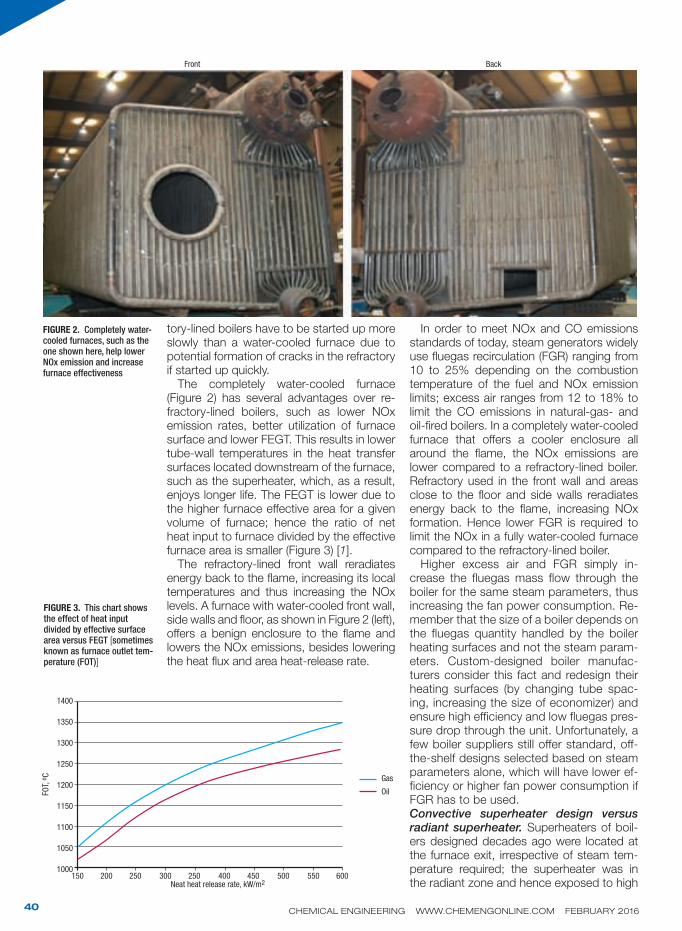
tory-lined boilers have to be started up more slowly than a water-cooled furnace due to potential formation of cracks in the refractory if started up quickly.
The completely water-cooled furnace (Figure 2) has several advantages over re-fractory-lined boilers, such as lower NOx emission rates, better utilization of furnace surface and lower FEGT. This results in lower tube-wall temperatures in the heat transfer surfaces located downstream of the furnace, such as the superheater, which, as a result, enjoys longer life. The FEGT is lower due to the higher furnace effective area for a given volume of furnace; hence the ratio of net heat input to furnace divided by the effective furnace area is smaller (Figure 3) [1].
The refractory-lined front wall reradiates energy back to the flame, increasing its local temperatures and thus increasing the NOx levels. A furnace with water-cooled front wall, side walls and floor, as shown in Figure 2 (left), offers a benign enclosure to the flame and lowers the NOx emissions, besides lowering the heat flux and area heat-release rate.
In order to meet NOx and CO emissions standards of today, steam generators widely use fluegas recirculation (FGR) ranging from 10 to 25% depending on the combustion temperature of the fuel and NOx emission limits; excess air ranges from 12 to 18% to limit the CO emissions in natural-gas- and oil-fired boilers. In a completely water-cooled furnace that offers a cooler enclosure all around the flame, the NOx emissions are lower compared to a refractory-lined boiler. Refractory used in the front wall and areas close to the floor and side walls reradiates energy back to the flame, increasing NOx formation. Hence lower FGR is required to limit the NOx in a fully water-cooled furnace compared to the refractory-lined boiler.
Higher excess air and FGR simply in-crease the fluegas mass flow through the boiler for the same steam parameters, thus increasing the fan power consumption. Re-member that the size of a boiler depends on the fluegas quantity handled by the boiler heating surfaces and not the steam param-eters. Custom-designed boiler manufac-turers consider this fact and redesign their heating surfaces (by changing tube spac-ing, increasing the size of economizer) and ensure high efficiency and low fluegas pres-sure drop through the unit. Unfortunately, a few boiler suppliers still offer standard, off-the-shelf designs selected based on steam parameters alone, which will have lower ef-ficiency or higher fan power consumption if FGR has to be used.Convective superheater design versus radiant superheater. Superheaters of boil-ers designed decades ago were located at the furnace exit, irrespective of steam tem-perature required; the superheater was in the radiant zone and hence exposed to high
FIGURE 2. Completely water-cooled furnaces, such as the one shown here, help lower NOx emission and increase furnace effectiveness
FIGURE 3. This chart shows the effect of heat input divided by effective surface area versus FEGT [sometimes known as furnace outlet tem-perature (FOT)]
Gas
OilFO
T, o
C
1400
1350
1300
1250
1200
1150
1100
1050
1000150 200 250 300 250 400 450 500 550 600
Neat heat release rate, kW/m2
Front Back

CHEMICAL ENGINEERING WWW.CHEMENGONLINE.COM FEBRUARY 201641
heat flux and direct radiation from the furnace flame, resulting often in tube failures (Figure 4A). These superheaters were called radiant superheaters. There is another option where the superheater is located in the convection bank itself, but without a screen. This is called a semi-radiant superheater (Figure 4B). Present-day designs from a few boiler suppliers who specialize in custom-designed units, have convective su-perheaters with a large screen section, shielding it from direct furnace radiation (Figure 4C).
A radiant superheater is not good choice for package boilers and is bet-ter avoided because the superheater is located in a harsh environment. A radiant superheater receives radiant energy from the furnace flame, while a convective superheater is shielded from furnace radiation because it is located in a much cooler region behind several rows of screen (evaporator) tubes.
A number of factors impact the design and thermal performance of semi-radiant or radiant superheaters and boiler plant engineers must be aware of them. Only then can they appreciate the fact that they are buying a design with great po-tential for tube overheating and failures.
It is difficult to estimate the FEGT ac-1. curately. A good boiler designer knows this. Variations in fuel analysis, excess air, furnace geometry, burner location and flame shape to mention a few, af-fect the FEGT, which in turn directly affects the superheater duty and tube wall temperature. The correlations for furnace performance are not clearly established (like the convective heat-transfer-coefficient correlations for flu-id flow inside or outside tubes, which you can see in any textbook on heat transfer). FEGT is mainly established based on field data of similar boiler designs and operating data. Variations of 50–120ºC are likely in its estimation, which can affect the energy transfer to the superheater and its tube wall temperature. The external radiation energy transferred to the superheater tubes will also be proportional to the FEGT to the power of four. One can appreciate the problem if, while esti-mating the FEGT, the designer comes up with a value like 1,000ºC while in operation it is close to 1,100ºC. The direct radiation will be higher by 35%
[(1,373)4 versus (1,273)4]. The loga-rithmic mean temperature difference (LMTD) in the superheater also will be affected, resulting in some uncer-tainty in the duty and performance evaluation of the superheater. A high-er LMTD than estimated will not only increase the duty of the superheater but will also increase the heat flux and the tube wall temperature.A semi-radiant superheater receives 2. direct radiation from the furnace and depending on the tube spacing-to-diameter ratio, the fraction of energy absorbed in each row will vary (Figure 5). If the superheater tubes are closely spaced, then more direct radiation
FIGURE 4C. Shown here is a convective superheater with vertical headers and horizontal tubes lo-cated beyond the screen section
FIGURE 4A. Depending on its location, a superheater can be either convective (left) or radiant (right). The numbers identify the superheater (1), burner (2) and screen, evaporator (3)
FIGURE 4B. A semi-radiant superheater without a screen section is shown here
Desuperheater
Desuperheater
Furnace
Furnace
Furnace
Furnace
13
1
3
2
2
Gas out
Gas out
Gas out
Burner
Burner
Evaporator
Evaporator
Evaporator
Screen
2 stage SH
2 stage SH
To economizer
To economizer
Gas in

CHEMICAL ENGINEERING WWW.CHEMENGONLINE.COM FEBRUARY 201642
will be absorbed by the superheater in the first two to three rows facing the furnace, thus increasing the tube wall temperature in these rows. Typically four to five rows of tubes absorb the complete external radia-tion, as seen from the chart in Figure 5. This adds to the heat flux inside the superheater tubes. Typically the tube wall temperature can go up by 20 to 40ºC due to external ra-diation; at tube wall operating temperatures close to 600–650ºC, even a 10ºC increase can result in tube failure. At partial loads, the increase in tube wall temperature will be higher, as shown in some worked out examples in Ref. 1.With uncertainty in the estimation of FEGT, 3. the direct radiation from furnace to the su-perheater is also difficult to predict. While evaluating the tube wall temperature in the superheater, one has to add the heat flux arising out of direct radiation, convection and non-luminous radiation. The contribu-tion of direct radiation is a function of the location of the tube facing the opening and the tube spacing as shown in Figure 5. It can be seen that when the tube spacing to the convection bank is large, a large amount of energy is sent to the next row and so on. The radiant superheater also absorbs more enthalpy at partial loads compared to full load. At low loads, the flow distribution on both gas and steam side will be poor. Hence tube overheating is likely at all loads [1].The turning section where the superheater 4. is located adds to non-uniformity in gas flow, velocity and temperature profiles across the superheater, making it difficult to predict its performance. A portion of
the superheater can have cross flow and a portion can have parallel flow and the frac-tion of each can vary with load. Thus its performance prediction becomes a guess-ing game. One is taking chances with such a location for the superheater. If the flame shape is not properly set, the 5. flame can lick the first few rows of su-perheater facing the furnace. Since the heat-transfer coefficient is much lower inside a superheater tube (about 6 to 10 times lower than that of the evaporator or furnace tubes), the increase in tube wall temperature can be high, leading to tube failures.On the other hand, the convective super-6. heater is located in a safe region far away from the furnace outlet. The number of screen rows (the function of screen tubes is the same as that of the evaporator) can be as high as 10 to even 40 rows depend-ing on steam temperature desired. There are three advantages of using a screen section. One, the gas temperature drops significantly before entering the super-heater say by 250–500ºF (depending on the number of screen rows) and the heat flux inside the tubes is significantly lower compared to the radiant design. The sec-ond is that the fluegas mixes well beyond the turn and becomes uniform before entering the superheater due to the gas pressure drop in the screen section, and hence the prediction of superheater per-formance is far more reliable, unlike the situation for a radiant superheater. Thirdly, the direct radiation contribution from the furnace is also avoided as the screen or evaporator tubes pick up the direct radia-tion and since the screen or evaporator tubes have a high-boiling heat-transfer coefficient inside the tubes (exceeding 2,500 Btu/ft2hºF compared to 200–350 Btu/ft2hºF for the superheater), the evap-orator tube wall temperature increase is not a concern at all. A major advantage for the convective su-7. perheater is its lower tube-wall tempera-ture, which results in a longer life com-pared to the radiant superheater. This is due to the lower gas-entering temperature and absence of direct radiation. A simplis-tic tube life calculation below illustrates this point.In heavy-oil-fired boilers, the slag formed 8. due to the melting of ash in fuel oil can deposit on a radiant superheater, which is operating at high temperature and can cause high-temperature corrosion failures,
FIGURE 5. This chart shows the distribution of external ra-diation from furnace to heat-ing surfaces at the furnace exit (Kn is fraction of direct radiation absorbed by each row and ST is the transverse spacing of tubes)
No. of rows deep n
Kn
1.0
0.9
0.8
0.7
0.6
0.5
0.4
0.3
0.2
0.1
01 2 4 6 8 10 12 14 16 18 20 22 24 26
ST/d
Distribution of external radiation to tubes
24222018
16
14
12
10
9
8
7
6
5
4
3
2
1
STO OO OO O
Gas flow

CHEMICAL ENGINEERING WWW.CHEMENGONLINE.COM FEBRUARY 201643
mainly due to vanadium, sodium salts and their compounds. The convective su-perheater can be located where fluegas temperatures are far below the slagging temperature.Variations in excess air, flame shape or 9. FGR will have a lesser effect on steam temperature in a convective superheater due to the additional cooling and mixing in the screen section ahead of the super-heater.
The boiler can be started up faster 10. because the gas temperature entering the superheater will be much lower in a convective design compared to the radi-ant design. If the guideline is, say, 600ºC maximum at the superheater, then it takes less time to reach this temperature with a convective superheater. A boiler with a radiant superheater has to be started up more slowly to ensure that 550–600ºC is not reached at the superheater before steam starts flowing through the super-heater. Hence the radiant or semi-radiant super-
heater design should be avoided if possible for a longer life of superheater and trouble-free operation as it poses more risks com-pared to a convective superheater.
This is not to say that all boilers with radiant superheaters will have problems in operation. Good radiant superheaters are designed with better materials, steam flow arrangement (referring to whether it is the primary or intermediate stage of superheating, and flow direction, whether parallel or counter flow) and high tube-side mass velocities and steam-side pressure drops to ensure trouble-free operation, but
it is an unnecessary risk for steam temper-atures up to 500ºC. High-pressure, high-temperature utility boilers, which operate at 165 kg/cm2g and 540–550ºC with re-heat require radiant designs as superheat-ers, and have to be located in high gas-temperature regions for compactness. But package boilers operating at much lower steam pressures need not have radiant or semi-radiant superheaters. The author has designed several hundred units with fully convective type superheaters which are in operation around the world without prob-lems since 1990. The only advantage of radiant design is that some surface area is reduced and hence labor costs are lower for superheater fabrication, but materials are costlier, and shorter life and frequent failures and repair costs more than com-pensate for this small advantage.
Types of superheatersBasically two types of superheater designs are available for package boilers and are widely used. One is the inverted loop super-heater (Figure 6A), and the other is the hori-zontal tube superheater (Figure 6B).Inverted loop. In the inverted loop design, the inlet and exit steam headers are hori-zontal and located inside or outside the gas path; baffle plates are used at appro-priate places in the header to obtain the necessary number of streams (or tubes carrying the total steam flow) in order to optimize the steam-side pressure drop. If 100,000 lb/h is the steam flowrate and there are six tubes on each header (12 across the boiler bank width) and, say, 20 rows deep (along gas flow direction) and
FIGURE 6A. Shown here is a superheater with a vertical tube of inverted loop design
FIGURE 6B. Two different views of a superheater with a hori-zontal tube design
CHEMICAL ENGINEERING WWW.CHEMENGONLINE.COM FEBRUARY 201644
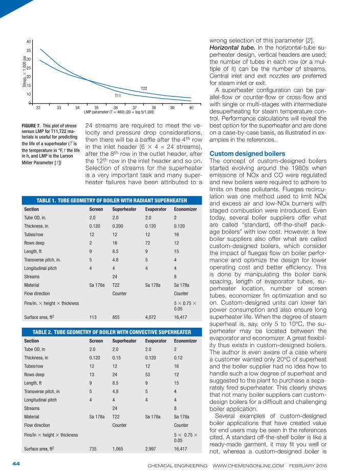
24 streams are required to meet the ve-locity and pressure drop considerations, then there will be a baffle after the 4th row in the inlet header (6 × 4 = 24 streams), after the 8th row in the outlet header, after the 12th row in the inlet header and so on. Selection of streams for the superheater is a very important task and many super-heater failures have been attributed to a
wrong selection of this parameter [2].Horizontal tube. In the horizontal-tube su-perheater design, vertical headers are used; the number of tubes in each row (or a mul-tiple of it) can be the number of streams. Central inlet and exit nozzles are preferred for steam inlet or exit.
A superheater configuration can be par-allel-flow or counter-flow or cross-flow and with single or multi-stages with intermediate desuperheating for steam temperature con-trol. Performance calculations will reveal the best option for the superheater and are done on a case-by-case basis, as illustrated in ex-amples in the references.
Custom designed boilersThe concept of custom-designed boilers started evolving around the 1980s when emissions of NOx and CO were regulated and new boilers were required to adhere to limits on these pollutants. Fluegas recircu-lation was one method used to limit NOx and excess air and low-NOx burners with staged combustion were introduced. Even today, several boiler suppliers offer what are called “standard, off-the-shelf pack-age boilers” with low cost. However, a few boiler suppliers also offer what are called custom-designed boilers, which consider the impact of fluegas flow on boiler perfor-mance and optimize the design for lower operating cost and better efficiency. This is done by manipulating the boiler bank spacing, length of evaporator tubes, su-perheater location, number of screen tubes, economizer fin optimization and so on. Custom-designed units can lower fan power consumption and also ensure long superheater life. When the degree of steam superheat is, say, only 5 to 10ºC, the su-perheater may be located between the evaporator and economizer. A great flexibil-ity thus exists in custom-designed boilers. The author is even aware of a case where a customer wanted only 20ºC of superheat and the boiler supplier had no idea how to handle such a low degree of superheat and suggested to the plant to purchase a sepa-rately fired superheater. This clearly shows that not many boiler suppliers can custom-design boilers for a difficult and challenging boiler application.
Several examples of custom-designed boiler applications that have created value for end users may be seen in the references cited. A standard off-the-shelf boiler is like a ready-made garment, it may fit you well or not, whereas a custom-designed boiler is
FIGURE 7. This plot of stress versus LMP for T11,T22 ma-terials is useful for predicting
the life of a superheater (T is
the temperature in °F, t the life in h, and LMP is the Larson
Miller Parameter [1])
TABLE 1. TUBE GEOMETRY OF BOILER WITH RADIANT SUPERHEATER
Section Screen Superheater Evaporator Economizer
Tube OD, in. 2.0 2.0 2.0 2
Thickness, in. 0.120 0.200 0.120 0.120
Tubes/row 12 12 12 16
Rows deep 2 16 72 12
Length, ft 9 8.5 9 15
Transverse pitch, in. 5 4.8 5 4
Longitudinal pitch 4 4 4 4
Streams 24 8
Material Sa 178a T22 Sa 178a Sa 178a
Flow direction Counter Counter
Fins/in. × height × thickness 5 × 0.75 × 0.05
Surface area, ft2 113 855 4,072 16,417
TABLE 2. TUBE GEOMETRY OF BOILER WITH CONVECTIVE SUPERHEATER
Section Screen Superheater Evaporator Economizer
Tube OD, in 2.0 2.0 2.0 2
Thickness, in 0.120 0.15 0.120 0.12
Tubes/row 12 12 12 16
Rows deep 13 24 53 12
Length, ft 9 8.5 9 15
Transverse pitch, in 5 4.8 5 4
Longitudinal pitch 4 4 4 4
Streams 24 8
Material Sa 178a T22 Sa 178a Sa 178a
Flow direction Counter Counter
Fins/in × height × thickness 5 × 0.75 × 0.05
Surface area, ft2 735 1,065 2,997 16,417
T22
Str
ess,
× 1
,000 p
si
40
35
30
25
20
15
10
032 33 34 35 36 37 38 39 40
LMP parameter (T + 460) (20 + log t)/1,000
T11

CHEMICAL ENGINEERING WWW.CHEMENGONLINE.COM FEBRUARY 201645
like a tailor-made dress that fits perfectly. Designs of standard boilers were devel-
oped several decades ago when there were no emission regulations. As mentioned ear-lier The FGR and excess air rates will vary with type of fuel, combustion temperature, NOx and CO emission limits, and hence, two boilers with identical steam parameters may differ in size depending on the total flu-egas quantity flowing through the unit. Stan-dard boiler suppliers have fewer options to choose from and one has to carefully review the efficiency, fan power consumption and overall performance.
Convective versus radiant superheatersIn order to understand how boilers with radi-ant versus convective superheaters differ in performance, an example is now presented.Design and operating parameters. A boiler is designed to deliver 137,000 lb/h of steam at 720 psig and 800ºF, with a feed-water temperature of 230ºF. Fuel is natural gas (90% methane, 5% ethane and 5% ni-trogen). Tables 1 and 2 show the tube ge-ometry that is used for both designs. The radiant superheater is located at the turn-ing section as shown in Figure 4B, while the convective superheater is located sev-eral rows downstream of the screen sec-tion (Figure 4C). The superheated steam temperature is uncontrolled as variations up to ±20°F are accepted by the plant. Furnace dimensions are the same for both options, namely 30-ft long, 8.5-ft high and 7-ft wide, and is a completely water-cooled furnace. The same economizer is used in both options. The only difference is in the tube thickness of the superheater and the number of rows of screen and evaporator. Excess air used is 15% and no fluegas re-circulation is used in the basic design. The same boiler is likely to operate with 20% fluegas recirculation (FGR) later. The per-formance for both designs was calculated and the results are presented in Table 3 (Design and off-design calculation meth-ods for superheaters and tube-wall tem-perature are detailed in Ref. 2).Discussions on the two designs. The fol-lowing points may be noted from Table 3.
Though the steam temperature is nearly 1. the same at 100% load for both the radi-ant and convective designs, the tube wall temperature for the radiant design is about 1,085ºF versus 1,020ºF for the convective design. This is due to the higher gas tem-perature (nearly 400ºF) entering the radiant superheater and with some contribution
from direct radiation from the furnace. By using a slightly higher tube thickness, the same superheater material can be used for both the radiant and convective design.The life of the superheater is significantly 2. reduced due to an increase in tube wall temperature. Let us estimate the life as-suming the boiler operates at 100% load all the time. Figure 7, showing the stress versus Larson Miller Parameter (LMP), is used to estimate the life [1].First estimate the operating stress, which
is given by the relation: Stress = pressure × radius/thickness.
For the radiant superheater: Stress = 720 × 1/0.2 = 3,600 psi. From Figure 6, the LMP corresponding to this value is 39. The absolute tube-wall temperature is found by T = 1,085 + 460 = 1,545ºR. 39,000/1,545 = 25.24 = (20 + log t) or t = 174,000 h or about 22 yr.
For the convective superheater: Stress = 720 × 1/0.15 = 4,800 psi. LMP = 38.3. T = 1,020 + 460=1,480°R. 38,300/1,480 = 25.87 = (20 + log t) or t=743,000 h or more than 92 yr.
Though this is a simplistic method of esti-mation of potential lifespan, it shows that the life of the convective design is much longer than that of the radiant design, due to the lower operating temperatures.
The surface area of the convective super-3. heater is much larger and hence costlier, but considering the low operating tube-wall temperature, it is considered a bet-ter design. The author has seen several superheaters with radiant design fail in a short period due to overheating. Frequent repairs and shutdowns are expensive and impacts the cost of business. As men-tioned earlier, there are non-uniformities in gas temperatures and fluegas flows entering the superheater, particularly if it
TABLE 3. PERFORMANCE OF BOILER WITH AND WITHOUT FGR
Item Radiant super-heater
Convective superheater
Radiant su-perheater
Convective superheater
Excess air,% 15 15 15 15
Fluegas Recirculation rate,% 0 0 20 20
Steam temp. at 100% load,±10ºF 807 812 777 800
SH tube wall temperature, ±10ºF 1,085 1,020 1,030 990
Gas temp to superheater, ±10ºF 2,379 1,980 2,138 1,828
Gas temp to evaporator, ±10ºF 1,897 1478 1,762 1,420
Gas temp to economizer, ,±10ºF 795 823 809 834
Gas temp leaving eco, ,±10ºF 300 300 320 324
Efficiency, % HHV 84.27 84.27 83.6 83.5
Steam temperature@ 50% load 815 767 814 785

CHEMICAL ENGINEERING WWW.CHEMENGONLINE.COM FEBRUARY 201646
is located at the turning section. Hence, prediction of its performance and tube wall temperature is less accurate compared to that of the convective design. When buy-ing new boilers, plant engineers should give preference to designs with convective superheaters and be aware of the likely problems with a radiant design. At par-tial loads, the steam flow inside the tubes also will have a non-uniformity due to low steam pressure drop and this can also add to the increase in tube wall temperature in certain tubes.Effect of adding FGR: As far as the steam 4. temperature is concerned, the variation in steam temperature is much larger be-tween 100 and 50% loads with a radiant superheater compared to the convective design, where the screen section damp-ens the large variations in fluegas flow and temperature.
Failure analysis The author was asked to investigate fre-quent tube-failure problems in an inverted-loop superheater with cross-flow design as shown in Figure 6A. This boiler could nei-ther be operated near 90–100% load nor at lower than 40% load, as tube failures would occur. This is a poor superheater design to start with and the author would have advised the plant against purchasing this boiler and to go for a design with a con-vective superheater. There were a few major
concerns with this design:Superheater location is at the turn around •section at the furnace exit with uncertain gas flow pattern and non-uniformity in flu-egas flow and gas temperaturesIt is a single-pass cross-flow design with •low steam-mass velocity inside the tubes and hence low steam-side pressure dropThe superheater is facing the furnace and •hence has direct radiation from the furnace in addition to convective and non-luminous heat fluxesLow steam-side pressure drop impacts •the downward flow of steam in long tubes, as explained belowOne of the problems with tall inverted-
loop superheaters is the effect of steam-side pressure drop at low loads as shown in Figure 8 when steam flow is in the vertical downward direction.
When steam flows upward, both the gravity loss and friction loss are additive and hence their sum is always positive and the total pressure loss versus flow curve is monotonic [2].
In the downward flow section, at low loads, the enthalpy pick up will be higher in a radiant superheater compared to a convective one (due to the contribution of furnace radiation) and the density of steam decreases and hence lower gravity loss. As steam flow increases, the specific vol-ume reaches a steady value and the steam density also will be higher while friction loss increases as the square of flow. The total loss curve will have two operating points as shown at low loads while at higher loads the total loss curve is monotonic and hence stagnation is not a concern. This trend is exhibited with a convective superheater also, but due to lower gas temperatures at lower loads, the tubes are much safer. Hence superheaters of inverted-loop de-sign should be designed with a reasonably high steam-side pressure drop, which en-sures gravity loss is not low enough at low loads to cause flow stagnation or ambigu-ity in flow. A “safe” pressure drop is arrived at in the design stage at 100% load based on steam pressure, height of superheater tubes and steam pressure. One has to also perform partial-load calculations and ensure flow stagnation will not be an issue. Unfor-tunately, many boiler designers do not un-derstand this, and design superheaters with a low steam-side pressure drop resulting in tube failures at low loads. Solution. Nothing much could be done about the location of the superheater. It was determined through calculations that the
FIGURE 8. Flow versus pres-sure drop in upward- and downward-flowing tubes
FIGURE 9. The problem of tube failures discussed in the text was solved with baffles and a parallel flow design
h
p
pp
p
–p
0
0
Total loss
Saturated steam out
Total loss
Gravity loss
Gravity loss
Friction loss
Friction loss
Mass loss m1
m1 m2 Mass loss
Upward flow Downward flow
Ambiguous region
+
+
+
+
Superheated steam out
Gas flow Gas flow
Upper header
Lower header
Mud drumSaturated steam in
present designSaturated steam in
Suggested modification

CHEMICAL ENGINEERING WWW.CHEMENGONLINE.COM FEBRUARY 201647
superheater was designed with a low steam pressure drop resulting in overheating of the tubes over a wide load range due to a low tube-side heat-transfer coefficient and direct radiation from the furnace. At lower loads, the problem became worse, as there was stagnation in some tubes due to the gravity head loss being higher than the steam pres-sure drop, as explained earlier. The boiler could be operated only in a narrow range of load and even then tube failures were rampant.
The author reviewed the design and introduced a baffle in the inlet header, thereby making the superheater a two-pass design with parallel flow configuration (Figure 9). This modifica-tion brought in several advantages.
The steam-side pressure drop in-1. creased eight times, which was still acceptable to the plant. The cooling effect of steam was much better and there were no concerns about stagnation at low loads.The parallel flow configuration took 2. away the higher steam tempera-
ture region into the cooler gas-temperature region, thus limiting the tube wall temperatures.
However, it should be noted that to begin with, the design could have been avoided. The best op-tion would have been to purchase a convective superheater with a large screen section with several advan-tages as cited earlier.
Concluding remarksPlants invest several million dollars in steam generators and should re-view if a particular design is good in the long run. Even if the superheater runs well, the higher tube wall tem-perature limits the life as shown earlier. A convective superheater design should be preferred. Though the steam generator may be slightly more expensive, it pays off in the long run due to lower maintenance and repair costs. Plants should also hire a consultant to review the boiler design from a thermal and process viewpoint instead of simply tak-ing the boiler suppliers’ words for
granted. Plant engineers should look at designs of custom-designed boilers and learn about their features and advantages and not simply buy a boiler because the same design has been offered by the boiler com-pany for five decades. n
Edited by Gerald Ondrey
References1. Ganapathy, V., ”Industrial Boilers and HRSGs,” CRC
Press, Florida, 2003.
2. Ganapathy, V., ”Steam Generators and Waste Heat Boilers for Process and Plant Engineers,” CRC Press, Florida, 2015.
AuthorViswanathan Ganapathy is a boiler consultant from Chennai, India ([email protected]), who specializes in thermal design and performance as-pects. He has over 40 years of experience in the thermal design and performance aspects of steam generators and waste-heat boilers. He has authored
over 250 articles on boiler-related subjects that have been published in a number of U.S., Indian and U.K. magazines. He has also authored several books and conducts courses on boilers. He graduated from the Institute of Technology (IIT) Madras with a degree in mechanical engineering.
American Filtration and Separations Society • May 9-11, 2016 • Houston Marriott Westchase, Houston, TX
Oil, Gas and Chemicals Filtration & Separations Conference – Expo
Don’t miss the premier iltration & separations Expo in the USA.Expo only passes are complimentary but registration in advance is required.
The American Filtration & Separations Society invites you to the Oil, Gas and Chemicals Filtration & Separations Conference
– Expo. Conference website: http://spring.afssociety.org/ David Engel – Conference Chair 832-296-6624
Conference Features• 3 Plenary sessions
• 3 Concurrent tracks
• 72 Technical papers
• Student Poster Competition
• Short Courses on Monday, May 9
Plenary Speakers
• Larry Ryan – Dow Chemical Company
• Michael Spearman – Otronix
• Scott Northrop – Exxon Mobil
Featured Topics• Filtration
• Coalescing
• Adsorption & Absorption
• Air/Gas Purification
• Bulk Separations and Cyclonics
• Chemical Assisted Separations
• Equipment & Systems
• Media Technology
• Produced Water
• R & D Innovation
Participating Companies• Berry Plastics (formerly AVINTIV)
• Delta Pure Filtration
• Dorstener Wire Tech
• GKD – USA Metal Fabrics
• IFTS
• Industrial Netting
• Nexo Solutions
• Onyx Specialty Paper
• Sefar
• Spifil Filtration
Circle 1 on p. 62 or go to adlinks.chemengonline.com/61492-01