federal aviation development of an administration improved ... · federal aviation development of...
TRANSCRIPT

Presented to:
Federal AviationAdministrationDevelopment of an
Improved Fire Test Method and Criteria for Aircraft Electrical Wiring
The International Aircraft Material Fire Testing Working Group
By: John Reinhardt, Project Manager, PMP
Date: June 17-18, 2008
Location: Niagara Falls, NY

22 of 39Federal AviationAdministration
Development of an Improved Fire Test Method and Criteria for Aircraft Electrical Wiring
Outline
• Project Initiating Process
Project Charter
Scope Statement
• Planning Process
Work Breakdown Structure
• Execution Process
Review Historical Information
Meet with Stakeholders
Definition of Fire Threat
Test Methods Selection
Material Selection
Material Testing
• Project Status & Final Words

33 of 39Federal AviationAdministration
Development of an Improved Fire Test Method and Criteria for Aircraft Electrical Wiring
• Objectives:
Develop a fire test method for aircraft electrical wiring that could adequately discriminate between poorly performing wire insulation materials and fire worthy ones when exposed to a realistic fire scenario.
• Requirements:
Submit a final report documenting the developmental project and the new test method.
• Due Date (milestone):
30 June 2009: Draft Final Report
Initiating Process
PROJECT CHARTER

44 of 39Federal AviationAdministration
Development of an Improved Fire Test Method and Criteria for Aircraft Electrical Wiring
Initiating Process

55 of 39Federal AviationAdministration
Development of an Improved Fire Test Method and Criteria for Aircraft Electrical Wiring
SCOPE STATEMENT• This project will focus on the flammability characteristics of aircraft wiring insulation only.
• It will consider the Radiant Heat Panel test apparatus as a candidate replacement.
• Excluded: wire arcing, design issues, installation issues, maintenance issues, FAA policies, etc.
Initiating Process
66 of 39Federal AviationAdministration
Development of an Improved Fire Test Method and Criteria for Aircraft Electrical Wiring
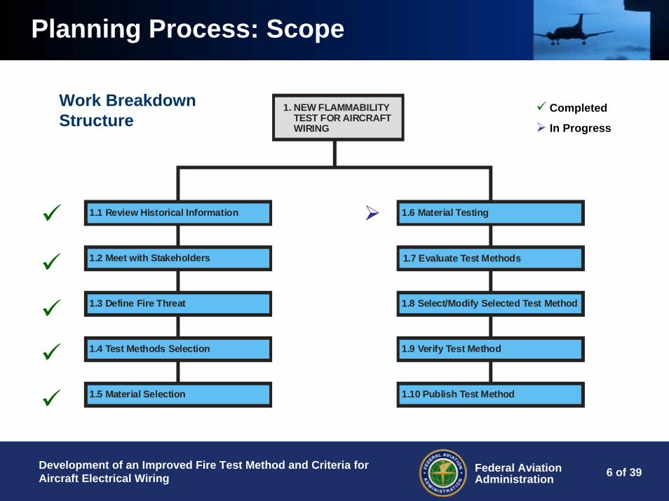
Work Breakdown Structure
1. NEW FLAMMABILITY TEST FOR AIRCRAFT WIRING
1.1 Review Historical Information
1.2 Meet with Stakeholders
1.4 Test Methods Selection
1.5 Material Selection
1.3 Define Fire Threat
1.6 Material Testing
1.7 Evaluate Test Methods
1.8 Select/Modify Selected Test Method
1.9 Verify Test Method
1.10 Publish Test Method
Completed
In Progress
Planning Process: Scope

77 of 39Federal AviationAdministration
Development of an Improved Fire Test Method and Criteria for Aircraft Electrical Wiring
WBS 1.1 Review Historical Information
Go BackGo Back
Execution Process: WBS 1.1
Organization Document Flammability Test Method
Federal Aviation Administration
Appendix F Part I of 14 CFR Part 23 & 25, and Aircraft Materials Fire Test Handbook DOT/FAA/AR-00/12 Chapter 4
Sixty Degree Bunsen Burner Test
Horizontal Flammability (Method No. 5211)Vertical Flammability (Method No. 5221) for MIL-
W rated wiresSpark Method Flammability (Method No. 5231)
International Electrotechnical Commission IEC 60332-3 Tests on Electric Cables Under Fire Conditions Part 3-10
National Fire Protection Association NFPA 262Standard Method of Test for Flame Travel and Smoke of Wires and Cables for Use in Air-Handling Spaces
SAE Aerospace Standard Method 801 Sixty Degree Bunsen Burner Test
UL 1666Test for Flame Propagation Height of Electrical and Optical-Fiber Cables Installed Vertically in
Shafts
UL 1685Vertical-Tray Fire-Propagation and Smoke-Release Test for Electrical and Optical-Fiber Cables
General Services Administration Federal Test Method Standard 228
Underwriter Laboratory

88 of 39Federal AviationAdministration
Development of an Improved Fire Test Method and Criteria for Aircraft Electrical Wiring
WBS 1.2 Meet with Stakeholders• FAA Sponsor
• FAA Program Manager
• FAA Fire Safety Researchers
• International Aircraft Materials Fire Test Working Group
• OEMs
• Other
Go Back
Execution Process: WBS 1.2

99 of 39Federal AviationAdministration
Development of an Improved Fire Test Method and Criteria for Aircraft Electrical Wiring
WBS 1.3 Define Fire Threat• Report DOT/FAA/AR-99/44 – “Development of Improved Flammability Criteria for Aircraft Thermal Acoustic Insulation,” September 2000
• And, Report DOT/FAA/AR-08/4 –“Development of an Improved Fire Test Method for Aircraft Ducting,” February 2008
• Fire Threat: 101.6 by 101.6 by 228.6-mm Urethane Foam Block (Density: 16.02 kg/m3)
• Environment:
Sea Level
Narrow-body attic
Insulation blankets in attic
Insulated duct in attic
Quasi-Std Ambient Temperature
Execution Process: WBS 1.3

1010 of 39Federal AviationAdministration
Development of an Improved Fire Test Method and Criteria for Aircraft Electrical Wiring
Execution Process: WBS 1.3

1111 of 39Federal AviationAdministration
Development of an Improved Fire Test Method and Criteria for Aircraft Electrical Wiring
INTERMEDIATE-SCALE FIRE TEST OF WIRES/CABLESIgnition Source Temperature Profile (Baseline)
0
100
200
300
400
500
600
700
800
900
1000
0 1 2 3 4 5 6 7 8 9 10 11 12 13 14 15
Time (Min)
Tem
pera
ture
(Deg
C)
Test 1Test 2Test 3Test 4
Tmax = 857 degCTavg = 810 degCt peak avg = 1.12 min

1212 of 39Federal AviationAdministration
Development of an Improved Fire Test Method and Criteria for Aircraft Electrical Wiring
INTERMEDIATE-SCALE FIRE TEST OF WIRES/CABLESIgnition Source Heat Flux Profile (Baseline)
0
10
20
30
40
50
60
70
80
90
100
0 1 2 3 4 5 6 7 8 9 10 11 12 13 14 15
Time (Min)
Hea
t Flu
x (W
/cm
2 )
Test 1Test 2Test 3Test 4
q. max = 90 W/cm2
q. avg = 77 W/cm2
t peak avg = 1.14 min
Go Back

1313 of 39Federal AviationAdministration
Development of an Improved Fire Test Method and Criteria for Aircraft Electrical Wiring
WBS 1.4 Test Methods Selection
60-Degree Bunsen Burner Test
Intermediate-Scale
Microscale Combustion Calorimeter
Radiant Heat Panel
Fire PropagationBurn AreaAfter Flame TimeDrip Flame TimeTotal Heat ReleaseHeat Release RateOnset TemperatureCombustion Temperature% Char
MEASUREMENTMATERIAL TEST METHOD
Execution Process: WBS 1.4
Go Back

1414 of 39Federal AviationAdministration
Development of an Improved Fire Test Method and Criteria for Aircraft Electrical Wiring
Execution Process: WBS 1.5
Go Back
Item No. Wire Specification AWG Insulation Material Jacket Material Temp Rating (degC) Comments
1 Hitachi Riser Cable Cat 3 PVC Fire Retardant Thermoplastic 60 Other Industry Usage
2 Hitachi Riser Cable (Cat 5e: ) Polyolefin Fire Retardant Thermoplastic 60 Use in other Industries; POLYOLEFIN: Polyethylene, Polypropylene, Cellular Polyolefin, Flame Retardant PE?
3Computer Cable Polypropylene Insulated, Belden 9804, 28 AWG, 2 pairs, shield: 90% overall foil/braid, drain wire overall
Polypropelene PVC 60 Use in other Industries
4 M17/28-RG58 (Coaxial Cable Type IIIA) PE PVC 80 Use in other Industries5 Neoprene Hook-up Wire Neoprene - 90 Use in other Industries6 MS 5086/1 (~ BMS13-13) 20 PVC Nylon 105 Past Aircraft Production7 Fiber Optic Riser Cable - PVC 105 Use in other Industries8 Hypalon Hook-up Wire Hypalon - 105 Use in other Industries
9 SAE AS 22759/14 20 Extruded FEP PVDF 135 Aircraft acceptable protected wire listed on FAA's Adisory Circular 43.13-1B Table 11-12, Past Aircraft Production
10 MS22759/16 20 ETFE - 150 Aircraft acceptable open wire listed on FAA's Adisory Circular 43.13-1B Table 11-11
11 MS 22759/32 20 Zelrad 150-S, XL-ETFE - 150Aircraft acceptable protected wire listed on FAA's Adisory
Circular 43.13-1B Table 11-12; Current In-Flight Entertainment/Other Passenger Systems
12 BMS13-48 (~ MS 22759/34) 20 ETFE - 150Aircraft acceptable open wire listed on Adisory Circular 43.13-1B
Table 11-11; Current Aircraft Production; Aircraft, In-Flight Entertainment/Other Passenger Systems
13 BMS13-60T01C01 20 Polyimide PTFE 150 Current Aircraft Production
14 MS 81044/6 (~ BMS13-38) 20 Crosslinked Polyalkene PVDF 150 Aircraft acceptable open wire listed on FAA's Adisory Circular 43.13-1B Table 11-11; Past Aircraft Production
15 MS 81381/21 20 Polyimide Tape Polyimide Resin 150 Aircraft acceptable protected wire listed on Adisory Circular 43.13-1B Table 11-12; Past Aircraft Production
16 Radix Braidless Silicone 150 Lead Wire Silicone Rubber - 150 Use in other Industries
17 SAE AS22759/33 20 Crosslinked ETFE Single Layer - 200Aircraft acceptable protected wire listed on FAA's Adisory
Circular 43.13-1B Table 11-12; Current In-Flight Entertainment/Other Passenger Systems
18 BMS13-55 20 Impregnated Inorganic Fiber PTFE 200 Current Aircraft Production19 BMS13-72 20 PTFE FEP 200 Current Aircraft Production
20 SAE AS 22759/5 20 Extruded PTFE - 200 Aircraft acceptable open wire listed on FAA's Adisory Circular 43.13-1B Table 11-11; Past Aircraft Production
21 SAE AS 22759/11 20 TFE - 200 Aircraft acceptable protected wire listed on FAA's Adisory Circular 43.13-1B Table 11-12; Past Aircraft Production
22 SAE AS22729 (MS 22759/86) 20 Composite: Fluoropolymer/Polyimide Tape - 260 Current Aircraft Production; Current In-Flight
Entertainment/Other Passenger Systems

1515 of 39Federal AviationAdministration
Development of an Improved Fire Test Method and Criteria for Aircraft Electrical Wiring
WBS 1.6 Material Testing• Tests to be conducted:
• 60-Degree Bunsen Burner Test
• Micro-Scale Combustion Calorimeter
• Intermediate-Scale Fire Test
• Radiant Heat Panel Test
• Other (as needed).
Execution Process: WBS 1.6

1616 of 39Federal AviationAdministration
Development of an Improved Fire Test Method and Criteria for Aircraft Electrical Wiring
Execution Process: WBS 1.6
Wire Specification Intermediate Scale Test 60 Degree Test MSCC Test RHP TestBaseline X N/A N/A
Belden 9804 Cable(PVC-PP) X X XBMS13-48 (Ex-XL-ETFE) X X
BMS13-55 (PTFE) X XBMS13-60 (PTFE-PI) X X X
BMS13-72 (FEP-PTFE) X XBraidless Silicone 200 Lead Wire X X XFiber Optic Cable M9B037 (PVC) X X X
Hitachi Riser Cable Cat 3 (FR-PVC) X XHitachi Riser Cable Cat 5e: (FR-PO) X X
Hypalon Hook-up Wire X X XM17/28-RG58 (PVC-PE) X X X
MS 22759/16 (ETFE) X XMS 22759/32 (Z-XL-M-ETFE) X X
MS 5086/1 (Nylon-PVC) X X XMS 81044/6 (XL-PA) X X X
MS 81381/21 (PI) X XNeoprene Hook-up Wire X XSAE AS 22759/11 (TFE) X X X
SAE AS 22759/14 (FEP-PVF2) X XSAE AS 22759/5 (Ar-TFE) X X
SAE AS22729 (FP-PI) X XSAE AS22759/33 (XL-ETFE) X X

1717 of 39Federal AviationAdministration
Development of an Improved Fire Test Method and Criteria for Aircraft Electrical Wiring
WBS 1.6 Material Testing• 60-DEGREE BUNSEN BURNER TEST FOR ELECTRIC WIRE
– Test Protocol: Chapter 4 of DOT/FAA/AR-00/12 “Aircraft Materials Fire Test Handbook”
– Sample Size: 76.2 cm (mark: 20.3 cm); mounted at 60 degrees from horizon
– Heat Source: Methane Flame (T>954C), perpendicular to wire sample
– Heat Source Exposure: 30 seconds
– Flame Extinguishing Time: <30 secs
– Burn Length: <7.6 cm
– Drip Extinguishing Time: <3 sec
Execution Process: WBS 1.6

1818 of 39Federal AviationAdministration
Development of an Improved Fire Test Method and Criteria for Aircraft Electrical Wiring
Wire Sample: BMS13-60 (Passed B.L. = 2.9 cm, FET = 0 sec)
1919 of 39Federal AviationAdministration
Development of an Improved Fire Test Method and Criteria for Aircraft Electrical Wiring
Wire Sample: MIL-17/28-RG58 (Passed, B.L. = 5.6 cm, FET = 3 sec)

2020 of 39Federal AviationAdministration
Development of an Improved Fire Test Method and Criteria for Aircraft Electrical Wiring
Wire Sample: MS5086/1 (PVC/Nylon, Failed: B.L. = 39.5 cm, FET = 156 sec)
2121 of 39Federal AviationAdministration
Development of an Improved Fire Test Method and Criteria for Aircraft Electrical Wiring
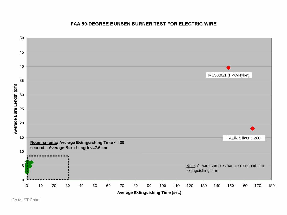
Execution Process: Material TestingFAA 60-DEGREE BUNSEN BURNER TEST FOR ELECTRIC WIRE
0
5
10
15
20
25
30
35
40
45
50
0 10 20 30 40 50 60 70 80 90 100 110 120 130 140 150 160 170 180
Average Extinguishing Time (sec)
Ave
rage
Bur
n Le
ngth
(cm
)
Radix Silicone 200
MS5086/1 (PVC/Nylon)
Note: All wire samples had zero second drip extinguishing time
Requirements: Average Extinguishing Time <= 30 seconds, Average Burn Length <=7.6 cm
Go to IST Chart

2222 of 39Federal AviationAdministration
Development of an Improved Fire Test Method and Criteria for Aircraft Electrical Wiring
Execution Process: Material TestingFAA 60-DEGREE BUNSEN BURNER TEST FOR ELECTRIC WIRE
0
1
2
3
4
5
6
7
8
9
10
0 1 2 3 4 5 6 7 8 9 10 11 12 13 14 15 16 17 18 19 20 21 22 23 24 25 26 27 28 29 30
Average Extinguishing Time (sec)
Ave
rage
Bur
n Le
ngth
(cm
)
MS81044/6 (XL-PA)
MIL17/28-RG58 (PVC/PE)
Note: All wire samples had zero second drip extinguishing time
Requirements: Average Extinguishing Time <= 30 seconds, Average Burn Length <=7.6 cm
Hypalon
Belden 9804 Cable (PVC-PP)Fiber Optic M9B037 (PVC)
MS22759/33 (XL-ETFE)MS22759/16 (ETFE)
BMS13-48 (EX-XL-ETFE)BMS13-55 (PTFE)MS22759/5 (TFE)
MS22759/14 (FEP-PVF2)MS22759/32 (Z-XL-M-ETFE)
MS22759/11 (TFE)BMS13-72 (FEP-PTFE)
MS81381/21 (PI)BMS13-60 (PTFE-PI)MS22759/86 (FP-PI)
Hitachi CAT 5eHitachi CAT 3

2323 of 39Federal AviationAdministration
Development of an Improved Fire Test Method and Criteria for Aircraft Electrical Wiring
Execution Process: Material TestingFAA 60-DEGREE BUNSEN BURNER TEST FOR ELECTRIC WIRE
0.03 0.03 0.03 0.030.07 0.07 0.07
0.10 0.10 0.10 0.100.13
0.20 0.200.23
0.30 0.30 0.30
0.60
0.70
1.10
0.00
0.20
0.40
0.60
0.80
1.00
1.20
BMS13-72
(FEP-P
TFE)
BMS13-60
(PTFE-P
I)
MS2275
9/32 (
Z-XL-M
-ETFE)
MS2275
9/5 (A
R-TFE)
BMS13-48
(EX-X
L-ETFE)
BMS13-55
(PTFE)
MS2275
9/33 (
XL-ETFE)
MS2275
9/14 (
FEP-PVF2)
MS2275
9/86 (
FP-PI)
MS2275
9/11 (
TFE)
Belden
9804
Cab
le (P
VC/PP)
MS8104
4/6 (X
L-PA)
MS2275
9/16 (
ETFE)
MS8138
1/21 (
PI)
MIL17/2
8-RG58
(PVC/P
E)
Hitach
i Cat
5e (F
R/Polyole
fin)
Hypalo
n
Fiber O
ptic M
9B03
7 (PVC)
Radix
Silicon
e 200
Hitach
i Cat
3 (FR/P
VC)
MS5086
/1 (N
ylon-P
VC)
Material ID
Mas
s Lo
ss (g
)
Note: Black color denotes that the conductor was exposed after the test; the Blue color denotes that it did not.

2424 of 39Federal AviationAdministration
Development of an Improved Fire Test Method and Criteria for Aircraft Electrical Wiring
WBS 1.6 Material Testing• MICRO-SCALE COMBUSTION CALORIMETER TEST
Execution Process: WBS 1.6
– Test Protocol: FAA Report DOT/FAA/AR-01/117 “A Micro-scale Combustion Calorimeter”
– Sample Size: milligram range
– Heat Source: Heating Coils (ramps up from 21 to 900 ºC)
– Heat Source Exposure: 1ºC per sec to effect pyrolysis
– Not a compliance test

2525 of 39Federal AviationAdministration
Development of an Improved Fire Test Method and Criteria for Aircraft Electrical Wiring
MICRO-SCALE COMBUSTION CALORIMETER TEST OF WIRES/CABLES
0
200
400
600
800
1000
1200
1400
272 284 292 294 300 306 317 319 344 491 498 499 501 501 502 505 517 534 534 604 612 615 626 627
Minimum Combustion Temperature (degC)
Hea
t Rel
ease
Cap
acity
(J/g
-K)
Hyp
alon
Mil1
7/28
-RG
58 (P
E)
Fibe
r Opt
ic (P
VC)
Neo
pren
e
9804
Cab
le (P
P/PV
C)
MS5
086
(Nyl
on/P
VC)
MS2
2759
/14
(FEP
/PVF
2)
Silic
one
200
BMS1
3-48
(EX-
XL-E
TFE)
MS2
2759
/32
(Zel
rad-
XL-E
TFE)
MS8
1044
/6 (P
VDF-
PA)
MS2
2759
/33
(XL-
ETFE
)
BMS1
3-55
(PTF
E)
BMS1
3-72
(FEP
-PTF
E)
MS2
2759
/5 (E
X-PT
FE)
BMS1
3-60
(PTF
E-PI
-PTF
E)
MS2
2759
/86
(FP-
PI)
MS8
1381
/21
(PI)
MS2
2759
/11
(TFE
)
MS2
2759
/16
(ETF
E)
Hita
chi C
AT 3
(Ins
ulat
ion)
Hita
chi C
AT 5
e (In
sula
tion)
Hita
chi C
AT 5
e (J
acke
t)
Hita
chi C
AT 3
(Jac
ket)

2626 of 39Federal AviationAdministration
Development of an Improved Fire Test Method and Criteria for Aircraft Electrical Wiring
MICRO-SCALE COMBUSTION CALORIMETER TEST OF WIRES/CABLES
0
5
10
15
20
25
30
35
40
45
MS8138
1/21 (
PI)
MS2275
9/86 (
FP-PI)
BMS13-60
(PTFE-P
I))
MS2275
9/11 (
TFE)
MS2275
9/5 (E
X-PTFE)
BMS13-55
(PTFE)
BMS13-72
(FEP-P
TFE)
MS2275
9/14 (
FEP-PVF2)
BMS13-48
(EX-X
L-ETFE)
MS2275
9/32 (
ZELRAD 15
0-S, X
L-ETFE)
MS2275
9/33 (
XL-ETFE)
Neopre
ne
MS2275
9/16 (
ETFE)
MS2275
9/16 (
ETFE)
Hitach
i Cat
3 (Ins
ulatio
n)Silic
one 2
00
Hitach
i Cat
3 (Ja
cket)
9804
Cab
le (P
P/PVC)
Hypalo
n
Hitach
i Cat
5 (Ja
cket)
Fiber O
ptic (
PVC)
MS8104
4-6 (P
VDF/XL P
olyalk
ene)
MS5086
-1 (N
ylon/P
VC)
MIL17/2
8-RG58
(PE)
Hitach
i Cat
5 (Ins
ulatio
n)
Material ID
Tota
l Hea
t Rel
ease
(kJ/
g)

2727 of 39Federal AviationAdministration
Development of an Improved Fire Test Method and Criteria for Aircraft Electrical Wiring
MICRO-SCALE COMBUSTION CALORIMETER TEST OF WIRES/CABLES
0%
10%
20%
30%
40%
50%
60%
70%
80%
90%
100%
BMS13-55
(PTFE)
BMS13-72
(FEP-P
TFE)
MS2275
9/11 (
TFE)
Hitach
i Cat
5 (Ins
ulatio
n)
MS2275
9/5 (E
xtrud
ed PTFE)
MIL17/2
8-RG58
(PE)
MS2275
9/16 (
ETFE)
MS2275
9/16 (
ETFE)
MS2275
9/14 (
FEP-PVF2)
MS2275
9/33 (
XL-ETFE)
MS2275
9/32 (
ZELRAD 15
0-S, X
L-ETFE)
MS5086
-1 (N
ylon/P
VC)
BMS13-60
(PTFE-P
I))
MS2275
9/86 (
FP-PI)
Fiber O
ptic (
PVC)
BMS13-48
(EX-X
L-ETFE)
MS8104
4-6 (P
VDF/XL P
olyalk
ene)
9804
Cab
le (P
P/PVC)
Hitach
i Cat
3 (Ja
cket)
Hitach
i Cat
3 (Ins
ulatio
n)
Material ID
Perc
ent C
har (
%)
2828 of 39Federal AviationAdministration
Development of an Improved Fire Test Method and Criteria for Aircraft Electrical Wiring
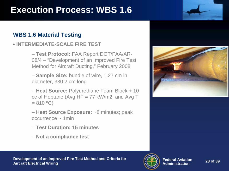
WBS 1.6 Material Testing• INTERMEDIATE-SCALE FIRE TEST
Execution Process: WBS 1.6
– Test Protocol: FAA Report DOT/FAA/AR-08/4 – “Development of an Improved Fire Test Method for Aircraft Ducting,” February 2008
– Sample Size: bundle of wire, 1.27 cm in diameter, 330.2 cm long
– Heat Source: Polyurethane Foam Block + 10 cc of Heptane (Avg HF = 77 kW/m2, and Avg T = 810 ºC)
– Heat Source Exposure: ~8 minutes; peak occurrence ~ 1min
– Test Duration: 15 minutes
– Not a compliance test

2929 of 39Federal AviationAdministration
Development of an Improved Fire Test Method and Criteria for Aircraft Electrical Wiring
Execution Process: WBS 1.6
Intermediate-Scale Fire Test Setup – Front View
Composite Ceiling Panel
(Nomex)
Fire Ignition Source(Urethane Foam Block
Soaked with 10 cc of Heptane)0.31 cm from Duct
TC1, TC2, TC3, TC4, TC5, TC6, Tc7C1, C2, C3
Note: TC: Thermocouple (2.54 cm below ceiling) C: Calorimeter Sensors 2.54 cm apart- Two more cameras (wide view)
Thermoacoustic InsulationBlanket (Polyimide film and Two 0.34 PCS FiberglassBlanket)
Insulated (PI/FG Blanket) Small Duct
(15.24 cm Height)
30.48 cm
Port Side Starboard Side
Narrow-body Transport Aircraft Fuselage Section

3030 of 39Federal AviationAdministration
Development of an Improved Fire Test Method and Criteria for Aircraft Electrical Wiring
365.76 cm
30.48 cm(Typical DistanceBetween TCs2-6)
11.43 cm
Fwd TC1, C1
Camera 3
15.24 cm
147.32 cm
13.33 cm
Forward
Aft
Mid TC4, C2
TC2
TC3
TC5
TC6
Wire/Cable Bundle (~½” Diameter)
Aft TC7, C3
313.69 cm
Fire Ignition Source
Camera 1
Camera 2
Intermediate-Scale Fire Test Setup – Top View
Execution Process: WBS 1.6

3131 of 39Federal AviationAdministration
Development of an Improved Fire Test Method and Criteria for Aircraft Electrical Wiring
Execution Process: WBS 1.6
Wire Sample: BMS13-60 (B.L. = 29.5 cm, FET = 1.33 min)

3232 of 39Federal AviationAdministration
Development of an Improved Fire Test Method and Criteria for Aircraft Electrical Wiring
Execution Process: WBS 1.6
Wire Sample: MIL-17/28-RG58 (B.L. = 109.8 cm, FET = 17.9 min, dripped)

3333 of 39Federal AviationAdministration
Development of an Improved Fire Test Method and Criteria for Aircraft Electrical Wiring
Execution Process: WBS 1.6
Wire Sample: MS5086/1 (B.L. = 101.7 cm, FET = 9.45 min)

3434 of 39Federal AviationAdministration
Development of an Improved Fire Test Method and Criteria for Aircraft Electrical Wiring
INTERMEDIATE-SCALE FIRE TEST OF WIRES/CABLES
0
100
200
300
400
500
600
700
800
900
1000
Baseline Belden 9804Cable (PVC-
PP)
BMS13-60(PTFE-PI)
MS22759/11(TFE)
MS81044/6(XL-PA)
Silicone 200 MIL17/28-RG58 (PVC-
PE)
Hypalon Fiber Optic(PVC)
MS5086/1(Nylon-PVC)
Material ID
Tem
pera
ture
(Deg
C)
Test 1
Test 2
Test 3
Test 4

3535 of 39Federal AviationAdministration
Development of an Improved Fire Test Method and Criteria for Aircraft Electrical Wiring
INTERMEDIATE-SCALE FIRE TEST OF WIRES/CABLES
0
20
40
60
80
100
120
Baseli
neMS22
759/1
1 (TFE)
MS8104
4/6 (X
L-PA)
BMS13-60
(PTFE-P
I)Fibe
r Opti
c (PVC)
Belden
9804
Cab
le (P
VC-PP)
Silicon
e 200
Hypalo
n
MIL17/2
8-RG58
(PVC-P
E)MS50
86/1
(Nylo
n-PVC)
Material ID
Hea
t Flu
x (W
/cm
2 )
Test 1Test 2Test 3Test 4

3636 of 39Federal AviationAdministration
Development of an Improved Fire Test Method and Criteria for Aircraft Electrical Wiring
INTERMEDIATE-SCALE FIRE TEST OF WIRES/CABLES
0
20
40
60
80
100
120
140
0 2 4 6 8 10 12 14 16 18 20
Maximum Extinguishing Time (min)
Max
imum
Bur
n Le
ngth
(cm
)
MS5086/1 (PVC/Nylon)MIL17/28-RG58 (PVC-PE)
Belden 9804 Cable (PVC-PP)
MS22759/11 (TFE)
MS81044/6 (XL-PA)
BMS13-60 (PTFE-PI)Legend: Green Diamond - Passed FAA 60 Deg Fire Test Red Diamond - Failed FAA 60 Deg Fire Test
Silicone 200
Fiber Optic (PVC/Kevlar)
Hypalon
Go to 60 Degree Chart

3737 of 39Federal AviationAdministration
Development of an Improved Fire Test Method and Criteria for Aircraft Electrical Wiring
INTERMEDIATE-SCALE FIRE TEST OF WIRES/CABLES
0
20
40
60
80
100
120
MS22759/11(TFE)
BMS13-60(Composite)
MS81044/6 Fiber Optic(PVC)
Silicone 200 Belden 9804Cable (PVC-
PP)
MIL17/28-RG58(PVC/PE)
MS5086/1-20-9 Hypalon
Material ID
Mas
s Lo
ss (g
)
Note: Black color denotes that the conductor was exposed after the test; the Blue color denotes that it did not.

3838 of 39Federal AviationAdministration
Development of an Improved Fire Test Method and Criteria for Aircraft Electrical Wiring
Project Tasks % Completion = 61%Cost Performance Index = 1.02Schedule Performance Index = 0.99
Project Status

3939 of 39Federal AviationAdministration
Development of an Improved Fire Test Method and Criteria for Aircraft Electrical Wiring
Questions?Anyone interested in joining this task group? Task group (participatory discussion) meeting tomorrow.
Final Words
Go Back