fema 302 - nehrp reccomended provisions for seismic
TRANSCRIPT

Of the National Institute of Building Sciences
ProgramonImprovedSeismicSafetyProvisions
1997 Edition
NEHRP RECOMMENDED PROVISIONSFOR SEISMIC REGULATIONSFOR NEW BUILDINGSAND OTHER STRUCTURES
Part 1: Provisions (FEMA 302)

The Building Seismic Safety Council (BSSC) was established in 1979 under the auspices of the National Institute ofBuilding Sciences as an entirely new type of instrument for dealing with the complex regulatory, technical, social, andeconomic issues involved in developing and promulgating building earthquake hazard mitigation regulatory provisionsthat are national in scope. By bringing together in the BSSC all of the needed expertise and all relevant public and pri-vate interests, it was believed that issues related to the seismic safety of the built environment could be resolved and jur-isdictional problems overcome through authoritative guidance and assistance backed by a broad consensus.
The BSSC is an independent, voluntary membership body representing a wide variety of building community interests. Its fundamental purpose is to enhance public safety by providing a national forum that fosters improved seismic safetyprovisions for use by the building community in the planning, design, construction, regulation, and utilization of build-ings.
To fulfill its purpose, the BSSC: (1) promotes the development of seismic safety provisions suitable for use throughoutthe United States; (2) recommends, encourages, and promotes the adoption of appropriate seismic safety provisions involuntary standards and model codes; (3) assesses progress in the implementation of such provisions by federal, state,and local regulatory and construction agencies; (4) identifies opportunities for improving seismic safety regulations andpractices and encourages public and private organizations to effect such improvements; (5) promotes the development oftraining and educational courses and materials for use by design professionals, builders, building regulatory officials,elected officials, industry representatives, other members of the building community, and the public; (6) advises govern-ment bodies on their programs of research, development, and implementation; and (7) periodically reviews and eval-uates research findings, practices, and experience and makes recommendations for incorporation into seismic designpractices.
See Appendix E of the Commentary volume for a full description of BSSC activities.
BOARD OF DIRECTION: 1997
Chairman Eugene Zeller, City of Long Beach, California
Vice Chairman William W. Stewart, Stewart-Scholberg Architects, Clayton, Missouri (representing the AmericanInstitute of Architects)
Secretary Mark B. Hogan, National Concrete Masonry Association, Herndon, Virginia
Ex-Officio James E. Beavers, James E. Beavers Consultants, Oak Ridge, Tennessee
Members Eugene Cole, Carmichael, California (representing the Structural Engineers Association ofCalifornia); S. K. Ghosh, Portland Cement Association, Skokie, Illinois; Nestor Iwankiw, AmericanInstitute of Steel Construction, Chicago, Illinois; Gerald H. Jones, Kansas City, Missouri(representing the National Institute of Building Sciences); Joseph Nicoletti, URS/John A. Blumeand Associates, San Francisco, California (representing the Earthquake Engineering ResearchInstitute); Jack Prosek, Turner Construction Company, San Francisco, California (representing theAssociated General Contractors of America); W. Lee Shoemaker, Metal Building ManufacturersAssociation, Cleveland, Ohio; John C. Theiss, Theiss Engineers, Inc., St. Louis, Missouri(representing the American Society of Civil Engineers); Charles Thornton, Thornton-Tomasetti En-gineers, New York, New York (representing the Applied Technology Council); David P. Tyree,American Forest and Paper Association, Colorado Springs, Colorado; David Wismer, Departmentof Licenses and Inspections, Philadelphia, Pennsylvania (representing the Building Officials andCode Administrators International); Richard Wright, National Institute of Standards andTechnology, Gaithersburg, Maryland (representing the Interagency Committee for Seismic Safety inConstruction)
BSSC Staff James R. Smith, Executive Director; Claret M. Heider, Technical Writer-Editor/Program Manager;Thomas Hollenbach, Deputy Executive; Lee Lawrence Anderson, Director, Special Projects; MaryMarshall, Administrative Assistant; Patricia Blasi, Administrative Assistant

BSSC Program on Improved Seismic Safety Provisions
NEHRP RECOMMENDED PROVISIONS(National Earthquake Hazards Reduction Program)
FOR SEISMIC REGULATIONS
FOR NEW BUILDINGS AND
OTHER STRUCTURES
1997 EDITION
Part 1: PROVISIONS(FEMA 302)
Prepared by theBuilding Seismic Safety Council
for theFederal Emergency Management Agency
BUILDING SEISMIC SAFETY COUNCILWashington, D.C.
1997

ii
NOTICE: Any opinions, findings, conclusions, or recommendations expressed in this publication donot necessarily reflect the views of the Federal Emergency Management Agency. Additionally,neither FEMA nor any of its employees make any warranty, expressed or implied, nor assume anylegal liability or responsibility for the accuracy, completeness, or usefulness of any information,product, or process included in this publication.
This report was prepared under Contract EMW-C-4536 between the Federal EmergencyManagement Agency and the National Institute of Building Sciences.
Building Seismic Safety Council activities and products are described at the end of this report. Forfurther information, contact the Building Seismic Safety Council, 1090 Vermont, Avenue, N.W.,Suite 700, Washington, D.C. 20005; phone 202-289-7800; fax 202-289-1092; e-mail [email protected] of this report may be obtained by contacting the FEMA Publication Distribution Facility at1-800-480-2520.

iii
PREFACE
One of the primary goals of the Federal Emergency Management Agency (FEMA) and theNational Earthquake Hazards Reduction Program (NEHRP) is to encourage design and buildingpractices that address the earthquake hazard and minimize the resulting damage. Publication ofthe 1997 NEHRP Recommended Provisions for Seismic Regulation of New Buildings and OtherStructures represents a significant milestone in the continuing FEMA-sponsored effort to improvethe seismic safety of new structures in this country. Its publication marks the fourth in a plannedupdating of both the Provisions documents and several complementary publications. As in thecase of the earlier editions of the Provisions (1985, 1988, 1991, and 1994), FEMA is proud tohave been a participant in the Building Seismic Safety Council project and encourages widespreaddissemination and voluntary use of this consensus resource document.
The 1997 Provisions contains several major changes that have truly made this a milestonedocument. Probably the most significant change is the adoption of new spectral response seismicdesign maps reflecting seismic hazard maps recently completed by the U.S. Geological Survey. The new maps and accompanying design procedure were developed by the BSSC Seismic DesignProcedures Group in conjunction with Technical Subcommittee 2 of the Provisions UpdateCommittee, and FEMA is grateful for the hard work of all involved. A second significant changeis the improvement of design procedures for high-seismic, near-source areas, and FEMA wishesto thank those members of the Structural Engineers Association of California who devotedconsiderable time and energy to this aspect of the update process. Another change worth notingis that the steel structure design chapter now references a new consensus standard which ad-dresses the problems highlighted by the Northridge earthquake and reflects work done in aFEMA-funded project to resolve the welded steel moment resisting frame problem.
The above changes are but three of over 150 changes that were balloted by the BSSC memberorganizations. The number of changes considered was three times that involved in any of theearlier update efforts and is testament to the increased attention being paid to the Provisions. This is due in large part to the decision to use the 1997 Provisions as the basis for the seismicrequirements in the new International Building Code. FEMA welcomes this increased scrutinyand the chance to work with the International Code Council.
Looking ahead, FEMA has already contracted with BSSC for and work already has begin on theupdate process that will lead to the 2000 Provisions. In addition to the normal update procedure,this project is designed to continue the Provisions/International Building Code cooperative effortand to permit development of a simplified design procedure for use in areas of lower seismicity.
In conclusion, FEMA wishes to express its sincere gratitude for the unstinting efforts of a largenumber of volunteer experts and the BSSC Board of Directors and staff who made possible the1997 Provisions documents. Americans unfortunate enough to experience the earthquakes thatwill inevitably occur in this country in the future will owe much, perhaps even their very lives, tothe contributions of these individuals to the seismic safety of buildings. Without the dedication

iv
and hard work of these men and women, this document and all it represents with respect toearthquake risk mitigation would not have been possible.
Federal Emergency Management Agency

v
INTRODUCTION and ACKNOWLEDGMENTS
The 1997 Edition of the NEHRP Recommended Provisions for Seismic Regulations for NewBuildings and Other Structures is the fifth edition of the document and, like the 1985, 1988, 1991and 1994 Editions that preceded it, has the consensus approval of the Building Seismic SafetyCouncil membership. It represents a major product of the Council's multiyear, multitask Programon Improved Seismic Safety Provisions and is intended to continue to serve as a source documentfor use by any interested members of the building community. (For readers unfamiliar with theprogram, a detailed description of the BSSC’s purpose and activities concludes the Commentaryvolume.)
In September 1994, NIBS entered into a contract with FEMA for initiation of the 39-monthBSSC 1997 Provisions update effort. Late in 1994, the BSSC member organization representa-tives and alternate representatives and the BSSC Board of Direction were asked to identify indi-viduals to serve on the 1997 Provisions Update Committee (PUC) and its TechnicalSubcommittees (TSs).
The 1997 PUC was constituted early in 1995, and 12 PUC Technical Subcommittees wereestablished to address design criteria and analysis, foundations and geotechnical considerations,cast-in-place/precast concrete structures, masonry structures, steel structures, wood structures,mechanical-electrical systems and building equipment and architectural elements, qualityassurance, interface with codes and standards, composite steel and concrete structures, energydissipation and base isolation, and nonbuilding structures.
As part of this effort, the BSSC has developed a revised seismic design procedure for use byengineers and architects for inclusion in the 1997 NEHRP Recommended Provisions. Unlike thedesign procedure based on U.S. Geological Survey (USGS) peak acceleration and peak velocity-related acceleration ground motion maps developed in the 1970s and used in earlier editions ofthe Provisions, the new design procedure is based on recently revised USGS spectral responsemaps. The design procedure involves new design maps based on the USGS hazard maps and aprocess specified within the body of the Provisions. This task has been conducted with the coop-eration of the USGS (under a Memorandum of Understanding signed by the BSSC and USGS)and under the guidance of a five-member Management Committee (MC). A Seismic Design Pro-cedure Group (SDPG) has been responsible for developing the design procedure.
More than 200 individuals have participated in the 1997 update effort, and more than 165substantive proposals for change were developed. A series of editorial/organizational changesalso have been made. All draft TS, SDPG, and PUC proposals for change were finalized in lateFebruary 1997. In early March, the PUC Chairman presented to the BSSC Board of Directionthe PUC’s recommendations concerning proposals for change to be submitted to the BSSCmember organizations for balloting, and the Board accepted these recommendations.
The first round of balloting concluded in early June 1997. Of the 158 items on the official ballot,only 8 did not pass; however, many comments were submitted with “no” and “yes with

vi
reservations” votes. These comments were compiled for distribution to the PUC, which met inmid-July to review the comments, receive TS responses to the comments and recommendationsfor change, and formulate its recommendations concerning what items should be submitted to theBSSC member organizations for a second ballot. The PUC deliberations resulted in the decisionto recommend to the BSSC Board that 28 items be included in the second ballot. The PUCChairman subsequently presented the PUC’s recommendations to the Board, which acceptedthose recommendations.
The second round of balloting was completed in late October 1997. All but one proposal passed;however, a number of comments on virtually all the proposals were submitted with the ballots andwere immediately compiled for consideration by the PUC. The PUC Executive Committee met inDecember to formulate its recommendations to the Board, and the Board subsequently acceptedthose recommendations. The final versions of the Provisions and Commentary volumes,including as Appendix A in the Provisions volume a summary of the differences between the 1994and 1997 Editions, then were prepared and transmitted to FEMA for publication.
In presenting this 1997 Edition of the Provisions, the BSSC wishes to acknowledge theaccomplishments of the many individuals and organizations involved over the years. The BSSCprogram resulting in the first four editions of the Provisions, the 1997 update effort, and theinformation development/dissemination activities conducted to stimulate use of the Provisions hasbenefitted from the expertise of hundreds of specialists, many of whom have given freely of theirtime over many years.
With so many volunteers participating, it is difficult to single out a given number or group forspecial recognition without inadvertently omitting others without whose assistance the BSSCprogram could not have succeeded; nevertheless, the 1997 Edition of the Provisions would not becomplete without at least recognizing the following individuals to whom I, acting on behalf of theBSSC Board of Direction, heartily express sincerest appreciation:
! The members of the BSSC Provisions Update Committee, especially Chairman WilliamHolmes;
P The mapping Management Committee and its Seismic Design Procedures Group, especiallyChairman R. Joe Hunt;
! The members of the 12 PUC Technical Subcommittees; and
! Michael Mahoney, the FEMA Project Officer.
Appreciation also is due to the BSSC Executive Director James R. Smith and BSSC staffmembers Claret Heider and Thomas Hollenbach, all of whose talents and experience were crucialto conduct of the program.
At this point I, as Chairman, would like to express my personal gratitude to the members of theBSSC Board of Direction and to all those who provided advice, counsel, and encouragementduring conduct of the update effort or who otherwise participated in the BSSC program thatresulted in the 1997 NEHRP Recommended Provisions.
Eugene Zeller, Chairman, BSSC Board of Direction

vii
CONTENTS
NEHRP RECOMMENDED PROVISIONS FORSEISMIC REGULATIONS FOR NEW BUILDINGS AND OTHER STRUCTURES
1997 EDITION
Part 1: PROVISIONS
PREFACE . . . . . . . . . . . . . . . . . . . . . . . . . . . . . . . . . . . . . . . . . . . . . . . . . . . . . . . . . . . . . . iii
INTRODUCTION and ACKNOWLEDGMENTS . . . . . . . . . . . . . . . . . . . . . . . . . . . . . . . v
Chapter 1, GENERAL PROVISIONS . . . . . . . . . . . . . . . . . . . . . . . . . . . . . . . . . . . . . . . . . 1
1.1 PURPOSE . . . . . . . . . . . . . . . . . . . . . . . . . . . . . . . . . . . . . . . . . . . . . . . . . . . . . . . . . . . . . 11.2 SCOPE AND APPLICATION . . . . . . . . . . . . . . . . . . . . . . . . . . . . . . . . . . . . . . . . . . . . . . 11.2.1 Scope . . . . . . . . . . . . . . . . . . . . . . . . . . . . . . . . . . . . . . . . . . . . . . . . . . . . . . . . . . . . . . . 11.2.2 Additions . . . . . . . . . . . . . . . . . . . . . . . . . . . . . . . . . . . . . . . . . . . . . . . . . . . . . . . . . . . . . 21.2.3 Change of Use . . . . . . . . . . . . . . . . . . . . . . . . . . . . . . . . . . . . . . . . . . . . . . . . . . . . . . . . . 21.2.4 Alterations . . . . . . . . . . . . . . . . . . . . . . . . . . . . . . . . . . . . . . . . . . . . . . . . . . . . . . . . . . . . 21.2.5 Alternate Materials and Alternate Means and Methods of Construction . . . . . . . . . . . . . . 21.3 SEISMIC USE GROUPS . . . . . . . . . . . . . . . . . . . . . . . . . . . . . . . . . . . . . . . . . . . . . . . . . . 21.3.1 Seismic Use Group III . . . . . . . . . . . . . . . . . . . . . . . . . . . . . . . . . . . . . . . . . . . . . . . . . . . 21.3.2 Seismic Use Group II . . . . . . . . . . . . . . . . . . . . . . . . . . . . . . . . . . . . . . . . . . . . . . . . . . . . 31.3.3 Seismic Use Group I . . . . . . . . . . . . . . . . . . . . . . . . . . . . . . . . . . . . . . . . . . . . . . . . . . . . . 31.3.4 Multiple Use . . . . . . . . . . . . . . . . . . . . . . . . . . . . . . . . . . . . . . . . . . . . . . . . . . . . . . . . . . 31.3.5 Seismic Use Group III Structure Access Protection . . . . . . . . . . . . . . . . . . . . . . . . . . . . . 41.4 OCCUPANCY IMPORTANCE FACTOR . . . . . . . . . . . . . . . . . . . . . . . . . . . . . . . . . . . . . 4
Chapter 2, GLOSSARY AND NOTATIONS . . . . . . . . . . . . . . . . . . . . . . . . . . . . . . . . . . . . . 5
2.1 GLOSSARY . . . . . . . . . . . . . . . . . . . . . . . . . . . . . . . . . . . . . . . . . . . . . . . . . . . . . . . . . . . . 52.2 NOTATIONS . . . . . . . . . . . . . . . . . . . . . . . . . . . . . . . . . . . . . . . . . . . . . . . . . . . . . . . . . . 13
Chapter 3 , QUALITY ASSURANCE . . . . . . . . . . . . . . . . . . . . . . . . . . . . . . . . . . . . . . . . . 27
3.1 SCOPE . . . . . . . . . . . . . . . . . . . . . . . . . . . . . . . . . . . . . . . . . . . . . . . . . . . . . . . . . . . . . . . 273.2 QUALITY ASSURANCE . . . . . . . . . . . . . . . . . . . . . . . . . . . . . . . . . . . . . . . . . . . . . . . . 273.2.1 Details of Quality Assurance Plan . . . . . . . . . . . . . . . . . . . . . . . . . . . . . . . . . . . . . . . . . 283.2.2 Contractor Responsibility . . . . . . . . . . . . . . . . . . . . . . . . . . . . . . . . . . . . . . . . . . . . . . . . 283.3 SPECIAL INSPECTION . . . . . . . . . . . . . . . . . . . . . . . . . . . . . . . . . . . . . . . . . . . . . . . . . 283.3.1 Piers, Piles, Caissons . . . . . . . . . . . . . . . . . . . . . . . . . . . . . . . . . . . . . . . . . . . . . . . . . . . 283.3.2 Reinforcing Steel . . . . . . . . . . . . . . . . . . . . . . . . . . . . . . . . . . . . . . . . . . . . . . . . . . . . . . 28

viii
3.3.3 Structural Concrete . . . . . . . . . . . . . . . . . . . . . . . . . . . . . . . . . . . . . . . . . . . . . . . . . . . . 293.3.4 Prestressed Concrete . . . . . . . . . . . . . . . . . . . . . . . . . . . . . . . . . . . . . . . . . . . . . . . . . . . 293.3.5 Structural Masonry . . . . . . . . . . . . . . . . . . . . . . . . . . . . . . . . . . . . . . . . . . . . . . . . . . . . 293.3.6 Structural Steel . . . . . . . . . . . . . . . . . . . . . . . . . . . . . . . . . . . . . . . . . . . . . . . . . . . . . . . 293.3.7 Structural Wood . . . . . . . . . . . . . . . . . . . . . . . . . . . . . . . . . . . . . . . . . . . . . . . . . . . . . . 293.3.8 Cold–Formed Steel Framing . . . . . . . . . . . . . . . . . . . . . . . . . . . . . . . . . . . . . . . . . . . . . 293.3.9 Architectural Components . . . . . . . . . . . . . . . . . . . . . . . . . . . . . . . . . . . . . . . . . . . . . . . 303.3.10 Mechanical and Electrical Components . . . . . . . . . . . . . . . . . . . . . . . . . . . . . . . . . . . . 303.4 TESTING . . . . . . . . . . . . . . . . . . . . . . . . . . . . . . . . . . . . . . . . . . . . . . . . . . . . . . . . . . . . . 303.4.1 Reinforcing and Prestressing Steel . . . . . . . . . . . . . . . . . . . . . . . . . . . . . . . . . . . . . . . . . 303.4.2 Structural Concrete . . . . . . . . . . . . . . . . . . . . . . . . . . . . . . . . . . . . . . . . . . . . . . . . . . . . 313.4.3 Structural Masonry . . . . . . . . . . . . . . . . . . . . . . . . . . . . . . . . . . . . . . . . . . . . . . . . . . . . 313.4.5 Mechanical and Electrical Equipment . . . . . . . . . . . . . . . . . . . . . . . . . . . . . . . . . . . . . . . 313.4.6 Seismically Isolated Structures . . . . . . . . . . . . . . . . . . . . . . . . . . . . . . . . . . . . . . . . . . . . 313.5 STRUCTURAL OBSERVATIONS . . . . . . . . . . . . . . . . . . . . . . . . . . . . . . . . . . . . . . . . . 313.6 REPORTING AND COMPLIANCE PROCEDURES . . . . . . . . . . . . . . . . . . . . . . . . . . . 32
Chapter 4, GROUND MOTION . . . . . . . . . . . . . . . . . . . . . . . . . . . . . . . . . . . . . . . . . . . . . 334.1 PROCEDURES FOR DETERMINING MAXIMUM CONSIDERED EARTHQUAKEAND DESIGN EARTHQUAKE GROUND MOTION ACCELERATIONS AND RESPONSESPECTRA . . . . . . . . . . . . . . . . . . . . . . . . . . . . . . . . . . . . . . . . . . . . . . . . . . . . . . . . . . . . . . . . 334.1.1 Maximum Considered Earthquake Ground Motions . . . . . . . . . . . . . . . . . . . . . . . . . . . . 334.1.2 General Procedure for Determining Maximum Considered Earthquake and
Design Spectral Response Accelerations: . . . . . . . . . . . . . . . . . . . . . . . . . . . . . . . . . . . . 334.1.3 Site-Specific Procedure for Determining Ground Motion Accelerations . . . . . . . . . . . . . 394.2 SEISMIC DESIGN CATEGORY . . . . . . . . . . . . . . . . . . . . . . . . . . . . . . . . . . . . . . . . . . 404.2.1 Determination of Seismic Design Category . . . . . . . . . . . . . . . . . . . . . . . . . . . . . . . . . . 404.2.2 Site Limitation for Seismic Design Categories E and F . . . . . . . . . . . . . . . . . . . . . . . . . . 41
Chapter 5, STRUCTURAL DESIGN CRITERIA . . . . . . . . . . . . . . . . . . . . . . . . . . . . . . . . 43
5.1 REFERENCE DOCUMENT: . . . . . . . . . . . . . . . . . . . . . . . . . . . . . . . . . . . . . . . . . . . . . . 435.2 DESIGN BASIS . . . . . . . . . . . . . . . . . . . . . . . . . . . . . . . . . . . . . . . . . . . . . . . . . . . . . . . . 435.2.1 General . . . . . . . . . . . . . . . . . . . . . . . . . . . . . . . . . . . . . . . . . . . . . . . . . . . . . . . . . . . . . 435.2.2 Basic Seismic-Force-Resisting Systems . . . . . . . . . . . . . . . . . . . . . . . . . . . . . . . . . . . . . 435.2.3 Structure Configuration . . . . . . . . . . . . . . . . . . . . . . . . . . . . . . . . . . . . . . . . . . . . . . . . . 525.2.4 Redundancy . . . . . . . . . . . . . . . . . . . . . . . . . . . . . . . . . . . . . . . . . . . . . . . . . . . . . . . . . . 555.2.5 Analysis Procedures . . . . . . . . . . . . . . . . . . . . . . . . . . . . . . . . . . . . . . . . . . . . . . . . . . . . 565.2.6 Design, Detailing Requirements, and Structural Component Load Effects . . . . . . . . . . . 585.2.7 Combination of Load Effects . . . . . . . . . . . . . . . . . . . . . . . . . . . . . . . . . . . . . . . . . . . . 625.2.8 Deflection and Drift Limits . . . . . . . . . . . . . . . . . . . . . . . . . . . . . . . . . . . . . . . . . . . . . . 635.3 EQUIVALENT LATERAL FORCE PROCEDURE . . . . . . . . . . . . . . . . . . . . . . . . . . . . . 645.3.1 General . . . . . . . . . . . . . . . . . . . . . . . . . . . . . . . . . . . . . . . . . . . . . . . . . . . . . . . . . . . . . 645.3.2 Seismic Base Shear . . . . . . . . . . . . . . . . . . . . . . . . . . . . . . . . . . . . . . . . . . . . . . . . . . . . 645.3.3 Period Determination . . . . . . . . . . . . . . . . . . . . . . . . . . . . . . . . . . . . . . . . . . . . . . . . . . . 66

ix
5.3.4 Vertical Distribution of Seismic Forces . . . . . . . . . . . . . . . . . . . . . . . . . . . . . . . . . . . . . 675.3.5 Horizontal Shear Distribution . . . . . . . . . . . . . . . . . . . . . . . . . . . . . . . . . . . . . . . . . . . . . 685.3.6 Overturning . . . . . . . . . . . . . . . . . . . . . . . . . . . . . . . . . . . . . . . . . . . . . . . . . . . . . . . . . . 685.3.7 Drift Determination and P-Delta Effects . . . . . . . . . . . . . . . . . . . . . . . . . . . . . . . . . . . . . 695.4 MODAL ANALYSIS PROCEDURE . . . . . . . . . . . . . . . . . . . . . . . . . . . . . . . . . . . . . . . . 715.4.1 General . . . . . . . . . . . . . . . . . . . . . . . . . . . . . . . . . . . . . . . . . . . . . . . . . . . . . . . . . . . . . 715.4.2 Modeling . . . . . . . . . . . . . . . . . . . . . . . . . . . . . . . . . . . . . . . . . . . . . . . . . . . . . . . . . . . . 715.4.3 Modes . . . . . . . . . . . . . . . . . . . . . . . . . . . . . . . . . . . . . . . . . . . . . . . . . . . . . . . . . . . . . . 715.4.4 Modal Properties . . . . . . . . . . . . . . . . . . . . . . . . . . . . . . . . . . . . . . . . . . . . . . . . . . . . . . 715.4.5 Modal Base Shear . . . . . . . . . . . . . . . . . . . . . . . . . . . . . . . . . . . . . . . . . . . . . . . . . . . . . 725.4.6 Modal Forces, Deflections, and Drifts . . . . . . . . . . . . . . . . . . . . . . . . . . . . . . . . . . . . . . 735.4.7 Modal Story Shears and Moments . . . . . . . . . . . . . . . . . . . . . . . . . . . . . . . . . . . . . . . . . 745.4.8 Design Values . . . . . . . . . . . . . . . . . . . . . . . . . . . . . . . . . . . . . . . . . . . . . . . . . . . . . . . . 745.4.9 Horizontal Shear Distribution . . . . . . . . . . . . . . . . . . . . . . . . . . . . . . . . . . . . . . . . . . . . . 755.4.10 Foundation Overturning . . . . . . . . . . . . . . . . . . . . . . . . . . . . . . . . . . . . . . . . . . . . . . . . 755.4.11 P-Delta Effects . . . . . . . . . . . . . . . . . . . . . . . . . . . . . . . . . . . . . . . . . . . . . . . . . . . . . . 755.5 SOIL-STRUCTURE INTERACTION EFFECTS . . . . . . . . . . . . . . . . . . . . . . . . . . . . . . . 755.5.1 General . . . . . . . . . . . . . . . . . . . . . . . . . . . . . . . . . . . . . . . . . . . . . . . . . . . . . . . . . . . . . 755.5.2 Equivalent Lateral Force Procedure . . . . . . . . . . . . . . . . . . . . . . . . . . . . . . . . . . . . . . . . 755.5.3 Modal Analysis Procedure . . . . . . . . . . . . . . . . . . . . . . . . . . . . . . . . . . . . . . . . . . . . . . . 80
Chapter 6, ARCHITECTURAL, MECHANICAL, AND ELECTRICAL COMPONENTSDESIGN REQUIREMENTS . . . . . . . . . . . . . . . . . . . . . . . . . . . . . . . . . . . . . . . . . . . . . . . . 83
6.1 GENERAL . . . . . . . . . . . . . . . . . . . . . . . . . . . . . . . . . . . . . . . . . . . . . . . . . . . . . . . . . . . . 836.1.1 References and Standards . . . . . . . . . . . . . . . . . . . . . . . . . . . . . . . . . . . . . . . . . . . . . . . 846.1.2 Component Force Transfer . . . . . . . . . . . . . . . . . . . . . . . . . . . . . . . . . . . . . . . . . . . . . . 856.1.3 Seismic Forces . . . . . . . . . . . . . . . . . . . . . . . . . . . . . . . . . . . . . . . . . . . . . . . . . . . . . . . . 866.1.4 Seismic Relative Displacements . . . . . . . . . . . . . . . . . . . . . . . . . . . . . . . . . . . . . . . . . . . 876.1.5 Component Importance Factor . . . . . . . . . . . . . . . . . . . . . . . . . . . . . . . . . . . . . . . . . . . . 886.1.6 Component Anchorage . . . . . . . . . . . . . . . . . . . . . . . . . . . . . . . . . . . . . . . . . . . . . . . . . 886.1.7 Construction Documents . . . . . . . . . . . . . . . . . . . . . . . . . . . . . . . . . . . . . . . . . . . . . . . . 896.2 ARCHITECTURAL COMPONENT DESIGN . . . . . . . . . . . . . . . . . . . . . . . . . . . . . . . . . 906.2.1 General . . . . . . . . . . . . . . . . . . . . . . . . . . . . . . . . . . . . . . . . . . . . . . . . . . . . . . . . . . . . . 906.2.2 Architectural Component Forces and Displacements . . . . . . . . . . . . . . . . . . . . . . . . . . . 906.2.3 Architectural Component Deformation . . . . . . . . . . . . . . . . . . . . . . . . . . . . . . . . . . . . . . 916.2.4 Exterior Nonstructural Wall Elements and Connections . . . . . . . . . . . . . . . . . . . . . . . . . 916.2.5 Out-of-Plane Bending . . . . . . . . . . . . . . . . . . . . . . . . . . . . . . . . . . . . . . . . . . . . . . . . . . 926.2.6 Suspended Ceilings . . . . . . . . . . . . . . . . . . . . . . . . . . . . . . . . . . . . . . . . . . . . . . . . . . . . 926.2.7 Access Floors . . . . . . . . . . . . . . . . . . . . . . . . . . . . . . . . . . . . . . . . . . . . . . . . . . . . . . . . . 946.2.8 Partitions . . . . . . . . . . . . . . . . . . . . . . . . . . . . . . . . . . . . . . . . . . . . . . . . . . . . . . . . . . . . 946.2.9 Steel Storage Racks . . . . . . . . . . . . . . . . . . . . . . . . . . . . . . . . . . . . . . . . . . . . . . . . . . . . 946.3 MECHANICAL AND ELECTRICAL COMPONENT DESIGN . . . . . . . . . . . . . . . . . . . 946.3.1 General . . . . . . . . . . . . . . . . . . . . . . . . . . . . . . . . . . . . . . . . . . . . . . . . . . . . . . . . . . . . . 946.3.2 Mechanical and Electrical Component Forces and Displacements . . . . . . . . . . . . . . . . . . 95

x
6.3.3 Mechanical and Electrical Component Period . . . . . . . . . . . . . . . . . . . . . . . . . . . . . . . . . 966.3.4 Mechanical and Electrical Component Attachments . . . . . . . . . . . . . . . . . . . . . . . . . . . . 966.3.5 Component Supports . . . . . . . . . . . . . . . . . . . . . . . . . . . . . . . . . . . . . . . . . . . . . . . . . . . 976.3.6 Component Certification . . . . . . . . . . . . . . . . . . . . . . . . . . . . . . . . . . . . . . . . . . . . . . . . 976.3.7 Utility and Service Lines at Structure Interfaces . . . . . . . . . . . . . . . . . . . . . . . . . . . . . . . 976.3.8 Site-Specific Considerations . . . . . . . . . . . . . . . . . . . . . . . . . . . . . . . . . . . . . . . . . . . . . . 976.3.9 Storage Tanks . . . . . . . . . . . . . . . . . . . . . . . . . . . . . . . . . . . . . . . . . . . . . . . . . . . . . . . . 976.3.10 HVAC Ductwork . . . . . . . . . . . . . . . . . . . . . . . . . . . . . . . . . . . . . . . . . . . . . . . . . . . . . 976.3.11 Piping Systems . . . . . . . . . . . . . . . . . . . . . . . . . . . . . . . . . . . . . . . . . . . . . . . . . . . . . . . 986.3.12 Boilers and Pressure Vessels . . . . . . . . . . . . . . . . . . . . . . . . . . . . . . . . . . . . . . . . . . . . 996.3.13 Mechanical Equipment, Attachments, and Supports . . . . . . . . . . . . . . . . . . . . . . . . . . 1006.3.14 Electrical Equipment, Attachments, and Supports: . . . . . . . . . . . . . . . . . . . . . . . . . . . 1026.3.15 Alternative Seismic Qualification Methods . . . . . . . . . . . . . . . . . . . . . . . . . . . . . . . . . 1036.3.16 Elevator Design Requirements . . . . . . . . . . . . . . . . . . . . . . . . . . . . . . . . . . . . . . . . . . 103
Chapter 7, FOUNDATION DESIGN REQUIREMENTS . . . . . . . . . . . . . . . . . . . . . . . . . 105
7.1 GENERAL . . . . . . . . . . . . . . . . . . . . . . . . . . . . . . . . . . . . . . . . . . . . . . . . . . . . . . . . . . . 1057.2 STRENGTH OF COMPONENTS AND FOUNDATIONS . . . . . . . . . . . . . . . . . . . . . . 1057.2.1 Structural Materials . . . . . . . . . . . . . . . . . . . . . . . . . . . . . . . . . . . . . . . . . . . . . . . . . . . 1057.2.2 Soil Capacities . . . . . . . . . . . . . . . . . . . . . . . . . . . . . . . . . . . . . . . . . . . . . . . . . . . . . . . 1057.3 SEISMIC DESIGN CATEGORIES A AND B . . . . . . . . . . . . . . . . . . . . . . . . . . . . . . . . 1057.4 SEISMIC DESIGN CATEGORY C . . . . . . . . . . . . . . . . . . . . . . . . . . . . . . . . . . . . . . . . 1057.4.1 Investigation . . . . . . . . . . . . . . . . . . . . . . . . . . . . . . . . . . . . . . . . . . . . . . . . . . . . . . . . 1057.4.2 Pole-Type Structures . . . . . . . . . . . . . . . . . . . . . . . . . . . . . . . . . . . . . . . . . . . . . . . . . . 1057.4.3 Foundation Ties . . . . . . . . . . . . . . . . . . . . . . . . . . . . . . . . . . . . . . . . . . . . . . . . . . . . . . 1067.4.4 Special Pile Requirements . . . . . . . . . . . . . . . . . . . . . . . . . . . . . . . . . . . . . . . . . . . . . . 1067.5 SEISMIC DESIGN CATEGORIES D, E, AND F . . . . . . . . . . . . . . . . . . . . . . . . . . . . . 1077.5.1 Investigation . . . . . . . . . . . . . . . . . . . . . . . . . . . . . . . . . . . . . . . . . . . . . . . . . . . . . . . . 1077.5.2 Foundation Ties . . . . . . . . . . . . . . . . . . . . . . . . . . . . . . . . . . . . . . . . . . . . . . . . . . . . . . 1077.5.3 Liquefaction Potential and Soil Strength Loss . . . . . . . . . . . . . . . . . . . . . . . . . . . . . . . 1077.5.4 Special Pile Requirements . . . . . . . . . . . . . . . . . . . . . . . . . . . . . . . . . . . . . . . . . . . . . . 107
Chapter 8, STEEL STRUCTURE DESIGN REQUIREMENTS . . . . . . . . . . . . . . . . . . . 109
8.1 REFERENCE DOCUMENTS . . . . . . . . . . . . . . . . . . . . . . . . . . . . . . . . . . . . . . . . . . . . 1098.2 SEISMIC REQUIREMENTS FOR STEEL STRUCTURES . . . . . . . . . . . . . . . . . . . . . 1098.3 SEISMIC DESIGN CATEGORIES A, B, AND C . . . . . . . . . . . . . . . . . . . . . . . . . . . . . 1098.4 SEISMIC DESIGN CATEGORIES D, E, AND F . . . . . . . . . . . . . . . . . . . . . . . . . . . . . 1098.5 COLD-FORMED STEEL SEISMIC REQUIREMENTS . . . . . . . . . . . . . . . . . . . . . . . . 1098.5.1 Modifications to Ref. 8.4 . . . . . . . . . . . . . . . . . . . . . . . . . . . . . . . . . . . . . . . . . . . . . . . 1108.5.2 Modifications to Ref. 8.5 . . . . . . . . . . . . . . . . . . . . . . . . . . . . . . . . . . . . . . . . . . . . . . . 1108.6 LIGHT-FRAMED WALLS . . . . . . . . . . . . . . . . . . . . . . . . . . . . . . . . . . . . . . . . . . . . . . 1108.6.1 Boundary Members . . . . . . . . . . . . . . . . . . . . . . . . . . . . . . . . . . . . . . . . . . . . . . . . . . . 1108.6.2 Connections . . . . . . . . . . . . . . . . . . . . . . . . . . . . . . . . . . . . . . . . . . . . . . . . . . . . . . . . . 110

xi
8.6.3 Braced Bay Members . . . . . . . . . . . . . . . . . . . . . . . . . . . . . . . . . . . . . . . . . . . . . . . . . . 1108.6.4 Diagonal Braces . . . . . . . . . . . . . . . . . . . . . . . . . . . . . . . . . . . . . . . . . . . . . . . . . . . . . . 1108.7 SEISMIC REQUIREMENTS FOR STEEL DECK DIAPHRAGMS . . . . . . . . . . . . . . . 1118.8 STEEL CABLES . . . . . . . . . . . . . . . . . . . . . . . . . . . . . . . . . . . . . . . . . . . . . . . . . . . . . . 111
Chapter 9, CONCRETE STRUCTURE DESIGN REQUIREMENTS . . . . . . . . . . . . . . 113
9.1 REFERENCE DOCUMENTS: . . . . . . . . . . . . . . . . . . . . . . . . . . . . . . . . . . . . . . . . . . . . 1139.1.1 Modifications to Ref. 9-1 . . . . . . . . . . . . . . . . . . . . . . . . . . . . . . . . . . . . . . . . . . . . . . . 1139.2 BOLTS AND HEADED STUD ANCHORS IN CONCRETE . . . . . . . . . . . . . . . . . . . . 1239.2.1 Load Factor Multipliers . . . . . . . . . . . . . . . . . . . . . . . . . . . . . . . . . . . . . . . . . . . . . . . . 1239.2.2 Strength of Anchors . . . . . . . . . . . . . . . . . . . . . . . . . . . . . . . . . . . . . . . . . . . . . . . . . . . 1239.2.3 Strength Based on Tests . . . . . . . . . . . . . . . . . . . . . . . . . . . . . . . . . . . . . . . . . . . . . . . 1239.2.4 Strength Based on Calculations . . . . . . . . . . . . . . . . . . . . . . . . . . . . . . . . . . . . . . . . . . 1239.3 CLASSIFICATION OF SEISMIC-FORCE-RESISTING SYSTEMS . . . . . . . . . . . . . . . 1299.3.1 Classification of Moment Frames . . . . . . . . . . . . . . . . . . . . . . . . . . . . . . . . . . . . . . . . . 1299.3.2 Classification of Shear Walls . . . . . . . . . . . . . . . . . . . . . . . . . . . . . . . . . . . . . . . . . . . . 1309.4 SEISMIC DESIGN CATEGORY A . . . . . . . . . . . . . . . . . . . . . . . . . . . . . . . . . . . . . . . . 1309.5 SEISMIC DESIGN CATEGORY B . . . . . . . . . . . . . . . . . . . . . . . . . . . . . . . . . . . . . . . . 1319.5.1 Moment Frames . . . . . . . . . . . . . . . . . . . . . . . . . . . . . . . . . . . . . . . . . . . . . . . . . . . . . . 1319.6 SEISMIC DESIGN CATEGORY C . . . . . . . . . . . . . . . . . . . . . . . . . . . . . . . . . . . . . . . . 1319.6.1 Seismic-Force-Resisting Systems . . . . . . . . . . . . . . . . . . . . . . . . . . . . . . . . . . . . . . . . . 1319.6.2 Discontinuous Members . . . . . . . . . . . . . . . . . . . . . . . . . . . . . . . . . . . . . . . . . . . . . . . . 1319.6.3 Plain Concrete . . . . . . . . . . . . . . . . . . . . . . . . . . . . . . . . . . . . . . . . . . . . . . . . . . . . . . . 1319.7 SEISMIC DESIGN CATEGORIES D, E, OR F . . . . . . . . . . . . . . . . . . . . . . . . . . . . . . . 1329.7.1 Seismic-Force-Resisting Systems . . . . . . . . . . . . . . . . . . . . . . . . . . . . . . . . . . . . . . . . . 1329.7.2 Frame Members Not Proportioned to Resist Forces Induced by Earthquake Motions . . 1329.7.3 Plain Concrete . . . . . . . . . . . . . . . . . . . . . . . . . . . . . . . . . . . . . . . . . . . . . . . . . . . . . . . 132
Appendix to Chapter 9, REINFORCED CONCRETE STRUCTURAL SYSTEMS COMPOSED FROM INTERCONNECTED PRECAST ELEMENTS . . . . . . . . 133
Chapter 10, STEEL AND CONCRETE STRUCTURE DESIGN REQUIREMENTS . . 137
10.1 REFERENCE DOCUMENTS . . . . . . . . . . . . . . . . . . . . . . . . . . . . . . . . . . . . . . . . . . . 13710.2 REQUIREMENTS . . . . . . . . . . . . . . . . . . . . . . . . . . . . . . . . . . . . . . . . . . . . . . . . . . . . 137
Chapter 11, MASONRY STRUCTURE DESIGN REQUIREMENTS . . . . . . . . . . . . . . 139
11.1 GENERAL . . . . . . . . . . . . . . . . . . . . . . . . . . . . . . . . . . . . . . . . . . . . . . . . . . . . . . . . . . 13911.1.1 Scope . . . . . . . . . . . . . . . . . . . . . . . . . . . . . . . . . . . . . . . . . . . . . . . . . . . . . . . . . . . . 13911.1.2 Reference Documents . . . . . . . . . . . . . . . . . . . . . . . . . . . . . . . . . . . . . . . . . . . . . . . . 13911.1.3 Definitions . . . . . . . . . . . . . . . . . . . . . . . . . . . . . . . . . . . . . . . . . . . . . . . . . . . . . . . . . 13911.1.4 Notations . . . . . . . . . . . . . . . . . . . . . . . . . . . . . . . . . . . . . . . . . . . . . . . . . . . . . . . . . . 14211.2 CONSTRUCTION REQUIREMENTS . . . . . . . . . . . . . . . . . . . . . . . . . . . . . . . . . . . . 144

xii
11.2.1 General . . . . . . . . . . . . . . . . . . . . . . . . . . . . . . . . . . . . . . . . . . . . . . . . . . . . . . . . . . . 14411.2.2 Quality Assurance . . . . . . . . . . . . . . . . . . . . . . . . . . . . . . . . . . . . . . . . . . . . . . . . . . . 14411.3 GENERAL REQUIREMENTS . . . . . . . . . . . . . . . . . . . . . . . . . . . . . . . . . . . . . . . . . . 14411.3.1 Scope . . . . . . . . . . . . . . . . . . . . . . . . . . . . . . . . . . . . . . . . . . . . . . . . . . . . . . . . . . . . 14411.3.2 Empirical Masonry Design . . . . . . . . . . . . . . . . . . . . . . . . . . . . . . . . . . . . . . . . . . . . . 14411.3.3 Plain (Unreinforced) Masonry Design . . . . . . . . . . . . . . . . . . . . . . . . . . . . . . . . . . . . 14411.3.4 Reinforced Masonry Design . . . . . . . . . . . . . . . . . . . . . . . . . . . . . . . . . . . . . . . . . . . . 14411.3.5 Seismic Design Category A . . . . . . . . . . . . . . . . . . . . . . . . . . . . . . . . . . . . . . . . . . . . 14511.3.6 Seismic Design Category B . . . . . . . . . . . . . . . . . . . . . . . . . . . . . . . . . . . . . . . . . . . . 14511.3.7 Seismic Design Category C . . . . . . . . . . . . . . . . . . . . . . . . . . . . . . . . . . . . . . . . . . . . 14511.3.8 Seismic Design Category D . . . . . . . . . . . . . . . . . . . . . . . . . . . . . . . . . . . . . . . . . . . . 14611.3.9 Seismic Design Categories E and F . . . . . . . . . . . . . . . . . . . . . . . . . . . . . . . . . . . . . . 14711.3.10 Properties of Materials . . . . . . . . . . . . . . . . . . . . . . . . . . . . . . . . . . . . . . . . . . . . . . . 14711.3.11 Section Properties . . . . . . . . . . . . . . . . . . . . . . . . . . . . . . . . . . . . . . . . . . . . . . . . . . 14911.4 DETAILS OF REINFORCEMENT . . . . . . . . . . . . . . . . . . . . . . . . . . . . . . . . . . . . . . . 15311.4.1 General . . . . . . . . . . . . . . . . . . . . . . . . . . . . . . . . . . . . . . . . . . . . . . . . . . . . . . . . . . . 15311.4.2 Size of Reinforcement . . . . . . . . . . . . . . . . . . . . . . . . . . . . . . . . . . . . . . . . . . . . . . . . 15311.4.3 Placement Limits for Reinforcement . . . . . . . . . . . . . . . . . . . . . . . . . . . . . . . . . . . . . . 15311.4.4 Cover for Reinforcement . . . . . . . . . . . . . . . . . . . . . . . . . . . . . . . . . . . . . . . . . . . . . . 15311.4.5 Development of Reinforcement . . . . . . . . . . . . . . . . . . . . . . . . . . . . . . . . . . . . . . . . . 15411.5 STRENGTH AND DEFORMATION REQUIREMENTS . . . . . . . . . . . . . . . . . . . . . . 15611.5.1 General . . . . . . . . . . . . . . . . . . . . . . . . . . . . . . . . . . . . . . . . . . . . . . . . . . . . . . . . . . . 15611.5.2 Strength . . . . . . . . . . . . . . . . . . . . . . . . . . . . . . . . . . . . . . . . . . . . . . . . . . . . . . . . . . . 15611.5.3 Design Strength . . . . . . . . . . . . . . . . . . . . . . . . . . . . . . . . . . . . . . . . . . . . . . . . . . . . . 15611.5.4 Deformation Requirements . . . . . . . . . . . . . . . . . . . . . . . . . . . . . . . . . . . . . . . . . . . . 15711.6 FLEXURE AND AXIAL LOADS . . . . . . . . . . . . . . . . . . . . . . . . . . . . . . . . . . . . . . . . 15811.6.1 Scope . . . . . . . . . . . . . . . . . . . . . . . . . . . . . . . . . . . . . . . . . . . . . . . . . . . . . . . . . . . . 15811.6.2 Design Requirements of Reinforced Masonry Members . . . . . . . . . . . . . . . . . . . . . . . 15811.6.3 Design of Plain (Unreinforced) Masonry Members . . . . . . . . . . . . . . . . . . . . . . . . . . . 15911.7 SHEAR . . . . . . . . . . . . . . . . . . . . . . . . . . . . . . . . . . . . . . . . . . . . . . . . . . . . . . . . . . . . 15911.7.1 Scope . . . . . . . . . . . . . . . . . . . . . . . . . . . . . . . . . . . . . . . . . . . . . . . . . . . . . . . . . . . . 15911.7.2 Shear Strength . . . . . . . . . . . . . . . . . . . . . . . . . . . . . . . . . . . . . . . . . . . . . . . . . . . . . . 16011.7.3 Design of Reinforced Masonry Members . . . . . . . . . . . . . . . . . . . . . . . . . . . . . . . . . . 16011.7.4 Design of Plain (Unreinforced) Masonry Members . . . . . . . . . . . . . . . . . . . . . . . . . . . 16211.8 SPECIAL REQUIREMENTS FOR BEAMS . . . . . . . . . . . . . . . . . . . . . . . . . . . . . . . . 16211.9 SPECIAL REQUIREMENTS FOR COLUMNS . . . . . . . . . . . . . . . . . . . . . . . . . . . . . 16311.10 SPECIAL REQUIREMENTS FOR WALLS . . . . . . . . . . . . . . . . . . . . . . . . . . . . . . . 16311.11 SPECIAL REQUIREMENTS FOR SHEAR WALLS . . . . . . . . . . . . . . . . . . . . . . . . . 16411.11.1 Ordinary Plain Masonry Shear Walls . . . . . . . . . . . . . . . . . . . . . . . . . . . . . . . . . . . . 16411.11.2 Detailed Plain Masonry Shear Walls . . . . . . . . . . . . . . . . . . . . . . . . . . . . . . . . . . . . . 16411.11.3 Ordinary Reinforced Masonry Shear Walls . . . . . . . . . . . . . . . . . . . . . . . . . . . . . . . . 16411.11.4 Intermediate Reinforced Masonry Shear Walls . . . . . . . . . . . . . . . . . . . . . . . . . . . . . 16411.11.5 Special Reinforced Masonry Shear Walls . . . . . . . . . . . . . . . . . . . . . . . . . . . . . . . . . 16411.11.6 Flanged Shear Walls . . . . . . . . . . . . . . . . . . . . . . . . . . . . . . . . . . . . . . . . . . . . . . . . . 16511.11.7 Coupled Shear Walls . . . . . . . . . . . . . . . . . . . . . . . . . . . . . . . . . . . . . . . . . . . . . . . . 165

xiii
11.12 SPECIAL MOMENT FRAMES OF MASONRY . . . . . . . . . . . . . . . . . . . . . . . . . . . . 16611.12.1 Calculation of Required Strength . . . . . . . . . . . . . . . . . . . . . . . . . . . . . . . . . . . . . . . 16611.12.2 Flexural Yielding . . . . . . . . . . . . . . . . . . . . . . . . . . . . . . . . . . . . . . . . . . . . . . . . . . . 16611.12.3 Reinforcement . . . . . . . . . . . . . . . . . . . . . . . . . . . . . . . . . . . . . . . . . . . . . . . . . . . . . 16611.12.4 Wall Frame Beams . . . . . . . . . . . . . . . . . . . . . . . . . . . . . . . . . . . . . . . . . . . . . . . . . . 16611.12.5 Wall Frame Columns . . . . . . . . . . . . . . . . . . . . . . . . . . . . . . . . . . . . . . . . . . . . . . . . 16711.12.6 Wall Frame Beam-Column Intersection . . . . . . . . . . . . . . . . . . . . . . . . . . . . . . . . . . 16811.13 GLASS-UNIT MASONRY AND MASONRY VENEER . . . . . . . . . . . . . . . . . . . . . . 17011.13.1 Design Lateral Forces and Displacements . . . . . . . . . . . . . . . . . . . . . . . . . . . . . . . . . 17011.13.2 Glass-Unit Masonry Design . . . . . . . . . . . . . . . . . . . . . . . . . . . . . . . . . . . . . . . . . . . 17011.13.3 Masonry Veneer Design . . . . . . . . . . . . . . . . . . . . . . . . . . . . . . . . . . . . . . . . . . . . . . 170
Appendix to Chapter 11, ALTERNATIVE PROVISIONS FOR THE DESIGNOF MASONRY STRUCTURES . . . . . . . . . . . . . . . . . . . . . . . . . . . . . . . . . . . . . . . . . . . . . . 171
Chapter 12, WOOD STRUCTURE DESIGN REQUIREMENTS . . . . . . . . . . . . . . . . . . 173
12.1 GENERAL . . . . . . . . . . . . . . . . . . . . . . . . . . . . . . . . . . . . . . . . . . . . . . . . . . . . . . . . . . 17312.1.1 Scope . . . . . . . . . . . . . . . . . . . . . . . . . . . . . . . . . . . . . . . . . . . . . . . . . . . . . . . . . . . . 17312.1.2 Reference Documents . . . . . . . . . . . . . . . . . . . . . . . . . . . . . . . . . . . . . . . . . . . . . . . . 17312.1.3 Notations . . . . . . . . . . . . . . . . . . . . . . . . . . . . . . . . . . . . . . . . . . . . . . . . . . . . . . . . . . 17412.2 DESIGN METHODS . . . . . . . . . . . . . . . . . . . . . . . . . . . . . . . . . . . . . . . . . . . . . . . . . . 17412.2.1 Engineered Wood Design . . . . . . . . . . . . . . . . . . . . . . . . . . . . . . . . . . . . . . . . . . . . . . 17412.2.2 Conventional Light-Frame Construction . . . . . . . . . . . . . . . . . . . . . . . . . . . . . . . . . . . 17412.3 ENGINEERED WOOD CONSTRUCTION . . . . . . . . . . . . . . . . . . . . . . . . . . . . . . . . . 17512.3.1 General . . . . . . . . . . . . . . . . . . . . . . . . . . . . . . . . . . . . . . . . . . . . . . . . . . . . . . . . . . . 17512.3.2 Framing Requirements . . . . . . . . . . . . . . . . . . . . . . . . . . . . . . . . . . . . . . . . . . . . . . . . 17512.3.3 Deformation Compatibility Requirements . . . . . . . . . . . . . . . . . . . . . . . . . . . . . . . . . . 17512.3.4 Design Limitations . . . . . . . . . . . . . . . . . . . . . . . . . . . . . . . . . . . . . . . . . . . . . . . . . . . 17512.4 DIAPHRAGMS AND SHEAR WALLS . . . . . . . . . . . . . . . . . . . . . . . . . . . . . . . . . . . . 17812.4.1 Diaphragm and Shear Wall Aspect Ratios . . . . . . . . . . . . . . . . . . . . . . . . . . . . . . . . . 17812.4.2 Shear Resistance Based on Principles of Mechanics . . . . . . . . . . . . . . . . . . . . . . . . . . 17812.4.3 Sheathing Requirements . . . . . . . . . . . . . . . . . . . . . . . . . . . . . . . . . . . . . . . . . . . . . . . 17812.5 CONVENTIONAL LIGHT-FRAME CONSTRUCTION . . . . . . . . . . . . . . . . . . . . . . . 18012.5.1 Scope . . . . . . . . . . . . . . . . . . . . . . . . . . . . . . . . . . . . . . . . . . . . . . . . . . . . . . . . . . . . 18012.5.2 Braced Walls . . . . . . . . . . . . . . . . . . . . . . . . . . . . . . . . . . . . . . . . . . . . . . . . . . . . . . . 18512.5.3 Detailing Requirements . . . . . . . . . . . . . . . . . . . . . . . . . . . . . . . . . . . . . . . . . . . . . . . 18512.6 SEISMIC DESIGN CATEGORY A . . . . . . . . . . . . . . . . . . . . . . . . . . . . . . . . . . . . . . . 18812.7 SEISMIC DESIGN CATEGORIES B, C, AND D . . . . . . . . . . . . . . . . . . . . . . . . . . . . 18812.7.1 Conventional Light-Frame Construction . . . . . . . . . . . . . . . . . . . . . . . . . . . . . . . . . . . 18912.7.2 Engineered Construction . . . . . . . . . . . . . . . . . . . . . . . . . . . . . . . . . . . . . . . . . . . . . . 18912.8 SEISMIC DESIGN CATEGORIES E AND F . . . . . . . . . . . . . . . . . . . . . . . . . . . . . . . 18912.8.1 Limitations . . . . . . . . . . . . . . . . . . . . . . . . . . . . . . . . . . . . . . . . . . . . . . . . . . . . . . . . . 189

xiv
Chapter 13, SEISMICALLY ISOLATED STRUCTURES DESIGN REQUIREMENTS . . . . . . . . . . . . . . . . . . . . . . . . . . . . . . . . . . . . . . . . . . . . . . . . . . . . . . . 201
13.1 GENERAL . . . . . . . . . . . . . . . . . . . . . . . . . . . . . . . . . . . . . . . . . . . . . . . . . . . . . . . . . . 20113.2 CRITERIA SELECTION . . . . . . . . . . . . . . . . . . . . . . . . . . . . . . . . . . . . . . . . . . . . . . . 20113.2.1 Basis for Design . . . . . . . . . . . . . . . . . . . . . . . . . . . . . . . . . . . . . . . . . . . . . . . . . . . . . 20113.2.2 Stability of the Isolation System . . . . . . . . . . . . . . . . . . . . . . . . . . . . . . . . . . . . . . . . . 20113.2.3 Seismic Use Group . . . . . . . . . . . . . . . . . . . . . . . . . . . . . . . . . . . . . . . . . . . . . . . . . . 20113.2.4 Configuration Requirements . . . . . . . . . . . . . . . . . . . . . . . . . . . . . . . . . . . . . . . . . . . . 20113.2.5 Selection of Lateral Response Procedure . . . . . . . . . . . . . . . . . . . . . . . . . . . . . . . . . . 20113.3 EQUIVALENT LATERAL FORCE PROCEDURE . . . . . . . . . . . . . . . . . . . . . . . . . . . 20313.3.1 General . . . . . . . . . . . . . . . . . . . . . . . . . . . . . . . . . . . . . . . . . . . . . . . . . . . . . . . . . . . 20313.3.2 Deformation Characteristics of the Isolation System . . . . . . . . . . . . . . . . . . . . . . . . . . 20313.3.3 Minimum Lateral Displacements . . . . . . . . . . . . . . . . . . . . . . . . . . . . . . . . . . . . . . . . 30213.3.4 Minimum Lateral Forces . . . . . . . . . . . . . . . . . . . . . . . . . . . . . . . . . . . . . . . . . . . . . . 20613.3.5 Vertical Distribution of Force . . . . . . . . . . . . . . . . . . . . . . . . . . . . . . . . . . . . . . . . . . . 20713.3.6 Drift Limits . . . . . . . . . . . . . . . . . . . . . . . . . . . . . . . . . . . . . . . . . . . . . . . . . . . . . . . . 20813.4 DYNAMIC LATERAL RESPONSE PROCEDURE . . . . . . . . . . . . . . . . . . . . . . . . . . 20813.4.1 General . . . . . . . . . . . . . . . . . . . . . . . . . . . . . . . . . . . . . . . . . . . . . . . . . . . . . . . . . . . 20813.4.2 Isolation System and Structural Elements Below the Isolation System . . . . . . . . . . . . 20813.4.3 Structural Elements Above the Isolation System . . . . . . . . . . . . . . . . . . . . . . . . . . . . 20913.4.4 Ground Motion . . . . . . . . . . . . . . . . . . . . . . . . . . . . . . . . . . . . . . . . . . . . . . . . . . . . . 20913.4.5 Mathematical Model . . . . . . . . . . . . . . . . . . . . . . . . . . . . . . . . . . . . . . . . . . . . . . . . . 21013.4.6 Description of Analysis Procedures . . . . . . . . . . . . . . . . . . . . . . . . . . . . . . . . . . . . . . 21113.4.7 Design Lateral Force . . . . . . . . . . . . . . . . . . . . . . . . . . . . . . . . . . . . . . . . . . . . . . . . . . 21113.5 LATERAL LOAD ON ELEMENTS OF STRUCTURES AND NONSTRUCTURALCOMPONENTS SUPPORTED BY BUILDINGS . . . . . . . . . . . . . . . . . . . . . . . . . . . . . . . . 21213.5.1 General . . . . . . . . . . . . . . . . . . . . . . . . . . . . . . . . . . . . . . . . . . . . . . . . . . . . . . . . . . . 21213.5.2 Forces and Displacements . . . . . . . . . . . . . . . . . . . . . . . . . . . . . . . . . . . . . . . . . . . . . 21213.6 DETAILED SYSTEM REQUIREMENTS . . . . . . . . . . . . . . . . . . . . . . . . . . . . . . . . . . 21313.6.1 General . . . . . . . . . . . . . . . . . . . . . . . . . . . . . . . . . . . . . . . . . . . . . . . . . . . . . . . . . . . 21313.6.2 Isolation System . . . . . . . . . . . . . . . . . . . . . . . . . . . . . . . . . . . . . . . . . . . . . . . . . . . . 21313.6.3 Structural System . . . . . . . . . . . . . . . . . . . . . . . . . . . . . . . . . . . . . . . . . . . . . . . . . . . . 21413.7 FOUNDATIONS . . . . . . . . . . . . . . . . . . . . . . . . . . . . . . . . . . . . . . . . . . . . . . . . . . . . . 21513.8 DESIGN AND CONSTRUCTION REVIEW . . . . . . . . . . . . . . . . . . . . . . . . . . . . . . . . 21513.8.1 General . . . . . . . . . . . . . . . . . . . . . . . . . . . . . . . . . . . . . . . . . . . . . . . . . . . . . . . . . . . 21513.8.2 Isolation System . . . . . . . . . . . . . . . . . . . . . . . . . . . . . . . . . . . . . . . . . . . . . . . . . . . . 21513.9 REQUIRED TESTS OF THE ISOLATION SYSTEM . . . . . . . . . . . . . . . . . . . . . . . . . 21513.9.1 General . . . . . . . . . . . . . . . . . . . . . . . . . . . . . . . . . . . . . . . . . . . . . . . . . . . . . . . . . . . 21513.9.2 Prototype Tests . . . . . . . . . . . . . . . . . . . . . . . . . . . . . . . . . . . . . . . . . . . . . . . . . . . . . 21613.9.3 Determination of Force-Deflection Characteristics . . . . . . . . . . . . . . . . . . . . . . . . . . . 21713.9.4 Test Specimen Adequacy . . . . . . . . . . . . . . . . . . . . . . . . . . . . . . . . . . . . . . . . . . . . . . 21813.9.5 Design Properties of the Isolation System . . . . . . . . . . . . . . . . . . . . . . . . . . . . . . . . . 218
Appendix to Chapter 13, PASSIVE ENERGY DISSIPATION . . . . . . . . . . . . . . . . . . . . . . . 221

xv
Chapter 14, NONBUILDING STRUCTURE DESIGN REQUIREMENTS . . . . . . . . . . 223
14.1 GENERAL . . . . . . . . . . . . . . . . . . . . . . . . . . . . . . . . . . . . . . . . . . . . . . . . . . . . . . . . . . 22314.1.1 Scope . . . . . . . . . . . . . . . . . . . . . . . . . . . . . . . . . . . . . . . . . . . . . . . . . . . . . . . . . . . . 22314.1.2 Nonbuilding Structures Supported by Other Structures . . . . . . . . . . . . . . . . . . . . . . . 22314.1.3 Architectural, Mechanical, and Electrical Components . . . . . . . . . . . . . . . . . . . . . . . . 22414.1.4 Loads . . . . . . . . . . . . . . . . . . . . . . . . . . . . . . . . . . . . . . . . . . . . . . . . . . . . . . . . . . . . 22414.1.5 Fundamental Period . . . . . . . . . . . . . . . . . . . . . . . . . . . . . . . . . . . . . . . . . . . . . . . . . . 22414.1.6 Drift Limitations . . . . . . . . . . . . . . . . . . . . . . . . . . . . . . . . . . . . . . . . . . . . . . . . . . . . 22414.1.7 Materials Requirements . . . . . . . . . . . . . . . . . . . . . . . . . . . . . . . . . . . . . . . . . . . . . . . 22414.2 STRUCTURAL DESIGN REQUIREMENTS . . . . . . . . . . . . . . . . . . . . . . . . . . . . . . . 22414.2.1 Design Basis . . . . . . . . . . . . . . . . . . . . . . . . . . . . . . . . . . . . . . . . . . . . . . . . . . . . . . . 22414.2.2 Rigid Nonbuilding Structures . . . . . . . . . . . . . . . . . . . . . . . . . . . . . . . . . . . . . . . . . . . 22814.2.3 Deflection Limits and Structure Separation . . . . . . . . . . . . . . . . . . . . . . . . . . . . . . . . 22814.3 NONBUILDING STRUCTURES SIMILAR TO BUILDINGS . . . . . . . . . . . . . . . . . . 22814.3.1 General . . . . . . . . . . . . . . . . . . . . . . . . . . . . . . . . . . . . . . . . . . . . . . . . . . . . . . . . . . . 22814.3.2 Pipe Racks . . . . . . . . . . . . . . . . . . . . . . . . . . . . . . . . . . . . . . . . . . . . . . . . . . . . . . . . . 22914.3.3 Steel Storage Racks . . . . . . . . . . . . . . . . . . . . . . . . . . . . . . . . . . . . . . . . . . . . . . . . . . 22914.3.4 Electrical Power Generating Facilities . . . . . . . . . . . . . . . . . . . . . . . . . . . . . . . . . . . . 23014.3.5 Structural Towers for Tanks and Vessels . . . . . . . . . . . . . . . . . . . . . . . . . . . . . . . . . . 23014.3.6 Piers and Wharves . . . . . . . . . . . . . . . . . . . . . . . . . . . . . . . . . . . . . . . . . . . . . . . . . . . 23114.4 NONBUILDING STRUCTURES NOT SIMILAR TO BUILDINGS . . . . . . . . . . . . . . 23114.4.1 General . . . . . . . . . . . . . . . . . . . . . . . . . . . . . . . . . . . . . . . . . . . . . . . . . . . . . . . . . . . 23114.4.2 Earth Retaining Structures . . . . . . . . . . . . . . . . . . . . . . . . . . . . . . . . . . . . . . . . . . . . . 23114.4.3 Tanks and Vessels . . . . . . . . . . . . . . . . . . . . . . . . . . . . . . . . . . . . . . . . . . . . . . . . . . . 23114.4.4 Electrical Transmission, Substation, and Distribution Structures . . . . . . . . . . . . . . . . . 23214.4.5 Telecommunication Towers . . . . . . . . . . . . . . . . . . . . . . . . . . . . . . . . . . . . . . . . . . . . 23214.4.6 Stacks and Chimneys . . . . . . . . . . . . . . . . . . . . . . . . . . . . . . . . . . . . . . . . . . . . . . . . . 23214.4.7 Amusement Structures . . . . . . . . . . . . . . . . . . . . . . . . . . . . . . . . . . . . . . . . . . . . . . . . 23214.4.8 Special Hydraulic Structures . . . . . . . . . . . . . . . . . . . . . . . . . . . . . . . . . . . . . . . . . . . 23314.4.9 Buried Structures . . . . . . . . . . . . . . . . . . . . . . . . . . . . . . . . . . . . . . . . . . . . . . . . . . . . 23314.4.10 Inverted Pendulums . . . . . . . . . . . . . . . . . . . . . . . . . . . . . . . . . . . . . . . . . . . . . . . . . 233
Appendix to Chapter 14 . . . . . . . . . . . . . . . . . . . . . . . . . . . . . . . . . . . . . . . . . . . . . . . . . . . . . 235
Appendix A, DIFFERENCES BETWEEN THE 1994 AND 1997 EDITIONSOF THE NEHRP RECOMMENDED PROVISIONS . . . . . . . . . . . . . . . . . . . . . . . . . . . . . 255
Appendix B, BSSC 1997 UPDATE PROGRAM PARTICIPANTS . . . . . . . . . . . . . . . . . 301

xvi
NOTE: Earlier editions of the Provisions featured marginal lines tohighlight where changes had been made. Because the structure of theProvisions has been thoroughly revised for 1997 and a number of broadeditorial changes have been made, the marginal lines are not used. Rather,readers are urged to review Appendix A of this Provisions volume for adescription of the changes made and a comparison of the tables of contentsof the 1994 and 1997 Editions.

1
Chapter 1
GENERAL PROVISIONS
1.1 PURPOSE: The NEHRP Recommended Provisions for Seismic Regulations for NewBuildings and Other Structures (referred to hereinafter as the Provisions) present criteria for thedesign and construction of structures to resist earthquake ground motions. The purposes of theseProvisions are as follows:
1. To provide minimum design criteria for structures appropriate to their primary function anduse considering the need to protect the health, safety, and welfare of the general public byminimizing the earthquake-related risk to life and
2. To improve the capability of essential facilities and structures containing substantialquantities of hazardous materials to function during and after design earthquakes.
The design earthquake ground motion levels specified herein could result in both structural andnonstructural damage. For most structures designed and constructed according to theseProvisions, structural damage from the design earthquake ground motion would be repairablealthough perhaps not economically so. For essential facilities, it is expected that the damagefrom the design earthquake ground motion would not be so severe as to preclude continuedoccupancy and function of the facility. The actual ability to accomplish these goals depends upona number of factors including the structural framing type, configuration, materials, and as-builtdetails of construction. For ground motions larger than the design levels, the intent of theseProvisions is that there be a low likelihood of structural collapse.
1.2 SCOPE AND APPLICATION:
1.2.1 Scope: These Provisions shall apply to the design and construction of structures includingadditions, change of use, and alterations to resist the effects of earthquake motions. Everystructure, and portion thereof, shall be designed and constructed to resist the effects ofearthquake motions as prescribed by these Provisions.
Exceptions:
1. Detached one- and two-family dwellings located where S is less than 0.4g areDS
exempt from all requirements of these Provisions.
2. Detached one- and two-family wood frame dwellings located where S is equal to orDS
greater than 0.4g and that are designed and constructed in accordance with theconventional light frame construction provisions in Sec. 12.5 are exempt from allother requirements of these Provisions.
3. Agricultural storage structures intended only for incidental human occupancy areexempt from all requirements of these Provisions.

Provisions, Chapter 1
2
4. Structures located where S is less than or equal to 0.04g and S is less than or equal1 DS
to 0.15g shall only be required to comply with Sec. 5.2.6.1.
Structures shall be designed and constructed in accordance with these Provisions.
1.2.2 Additions: Additions shall be designed and constructed in accordance with the following:
1.2.2.1: An addition that is structurally independent from an existing structure shall be designedand constructed as required for a new structure in accordance with Sec. 1.2.1.
1.2.2.2: An addition that is not structurally independent from an existing structure shall bedesigned and constructed such that the entire structure conforms to the seismic-force- resistancerequirements for new structures unless all of the following conditions are satisfied:
1. The addition conforms with the requirements for new structures, and
2. The addition does not increase the seismic forces in any structural element of the existingstructure by more than 5 percent, unless the capacity of the element subject to the increasedforces is still in compliance with these Provisions, and
3. The addition does not decrease the seismic resistance of any structural element of the existingstructure to less than that required for a new structure.
1.2.3 Change of Use: When a change of use results in a structure being reclassified to a higherSeismic Use Group, the structure shall conform to the requirements of Section 1.2.1 for a newstructure.
Exception: When a change of use results in a structure being reclassified from SeismicUse Group I to Seismic Use Group II, compliance with these Provisions is not required ifthe structure is located where S is less than 0.3.DS
1.2.4 Alterations: Alterations are permitted to be made to any structure without requiring thestructure to comply with these Provisions provided the alterations conform to that required for anew structure. Alterations shall not decrease the lateral-force resisting system strength orstiffness to less than that required by these Provisions. The alteration shall not cause the existingstructural elements to be loaded beyond their capacity.
1.2.5 Alternate Materials and Alternate Means and Methods of Construction: Alternatematerials and alternate means and methods of construction to those prescribed in these Provisionsare permitted if approved by the authority having jurisdiction. Substantiating evidence shall besubmitted demonstrating that the proposed alternate, for the purpose intended, will be at leastequal in strength, durability, and seismic resistance.
1.3 SEISMIC USE GROUPS: All structures shall be assigned to one of the following SeismicUse Groups:
1.3.1 Seismic Use Group III: Seismic Use Group III structures are those having essentialfacilities that are required for post-earthquake recovery and those containing substantialquantities of hazardous substances including:
1. Fire, rescue, and police stations

General Provisions
3
2. Hospitals
3. Designated medical facilities having emergency treatment facilities
4. Designated emergency preparedness centers
5. Designated emergency operation centers
6. Designated emergency shelters
7. Power generating stations or other utilities required as emergency back-up facilities forSeismic Use Group III facilities
8. Emergency vehicle garages and emergency aircraft hangars
9. Designated communication centers
10. Aviation control towers and air traffic control centers
11. Structures containing sufficient quantities of toxic or explosive substances deemed to behazardous to the public
12. Water treatment facilities required to maintain water pressure for fire suppression.
1.3.2 Seismic Use Group II: Seismic Use Group II structures are those that have a substantialpublic hazard due to occupancy or use including:
1. Covered structures whose primary occupancy is public assembly with a capacity greater than300 persons
2. Educational structures through the 12th grade with a capacity greater than
3. Day care centers with a capacity greater than 150
4. Medical facilities with greater than 50 resident incapacitated patients not otherwise designateda Seismic Use Group III structure
5. Jails and detention facilities
6. All structures with a capacity greater than 5,000 persons
7. Power generating stations and other public utility facilities not included in Seismic Use GroupIII and required for continued operation
8. Water treatment facilities required for primary treatment and disinfection for potable water
9. Waste water treatment facilities required for primary treatment
1.3.3 Seismic Use Group I: Seismic Use Group I structures are those not assigned to SeismicUse Groups III or II.
1.3.4 Multiple Use: Structures having multiple uses shall be assigned the classification of theuse having the highest Seismic Use Group except in structures having two or more portionswhich are structurally separated in accordance with Sec. 5.2.8, each portion shall be separatelyclassified. Where a structurally separated portion of a structure provides access to, egress from,

Provisions, Chapter 1
4
or shares life safety components with another portion having a higher Seismic Use Group, thelower portion shall be assigned the same rating as the higher.
1.3.5 Seismic Use Group III Structure Access Protection: Where operational access to aSeismic Use Group III structure is required through an adjacent structure, the adjacent structureshall conform to the requirements for Seismic Use Group III structures. Where operationalaccess is less than 10 ft (3 m) from an interior lot line or less than 10 ft (3 m) from anotherstructure, access protection from potential falling debris shall be provided by the owner of theSeismic Use Group III structure.
1.4 OCCUPANCY IMPORTANCE FACTOR: An occupancy importance factor, I, shall beassigned to each structure in accordance with Table 1.4.
TABLE 1.4 Occupancy Importance Factors
Seismic Use Group I
I 1.0
II 1.25
III 1.5

5
Chapter 2
GLOSSARY AND NOTATIONS
2.1 GLOSSARY:
Active Fault: A fault for which there is an average historic slip rate of 1 mm per year or moreand geologic evidence of seismic activity within Holocene times (past 11,000 years).
Addition: An increase in building area, aggregate floor area, height, or number of stories of astructure.
Adjusted Resistance (D’): The reference resistance adjusted to include the effects of allapplicable adjustment factors resulting from end use and other modifying factors. Time effectfactor (88) adjustments are not included.
Alteration: Any construction or renovation to an existing structure other than an addition.
Appendage: An architectural component such as a canopy, marquee, ornamental balcony, orstatuary.
Approval: The written acceptance by the authority having jurisdiction of documentation thatestablishes the qualification of a material, system, component, procedure, or person to fulfill therequirements of these provisions for the intended use.
Architectural Component Support: Those structural members or assemblies of members,including braces, frames, struts and attachments, that transmit all loads and forces betweenarchitectural systems, components, or elements and the structure.
Attachments: Means by which components and their supports are secured or connected to theseismic-force-resisting system of the structure. Such attachments include anchor bolts, weldedconnections, and mechanical fasteners.
Base: The level at which the horizontal seismic ground motions are considered to be imparted tothe structure.
Base Shear: Total design lateral force or shear at the base.
Basement. A basement is any story below the lowest story above grade.
Boundary Elements: Diaphragm and shear wall boundary members to which sheathingtransfers forces. Boundary members include chords and drag struts at diaphragm and shear wallperimeters, interior openings, discontinuities, and re-entrant corners.

1997 Provisions, Chapter 2
6
Braced Wall Line: A series of braced wall panels in a single story that meets the requirementsof Sec. 12.5.2.
Braced Wall Panel: A section of wall braced in accordance with Sec. 12.5.2.
Building: Any structure whose use could include shelter of human occupants.
Boundary Members: Portions along wall and diaphragm edges strengthened by longitudinaland transverse reinforcement and/or structural steel members.
Cantilevered Column System: A seismic-force-resisting system in which lateral forces areresisted entirely by columns acting as cantilevers from the foundation.
Component: A part or element of an architectural, electrical, mechanical, or structural system.
Component, Equipment: A mechanical or electrical component or element that is part of amechanical and/or electrical system within or without a building system.
Component, Flexible: Component, including its attachments, having a fundamental periodgreater than 0.06 sec.
Component, Rigid: Component, including its attachments, having a fundamental period lessthan or equal to 0.06 sec.
Concrete:
Plain Concrete: Concrete that is either unreinforced or contains less reinforcement than theminimum amount specified in Ref. 6-1 for reinforced concrete.
Reinforced Concrete: Concrete reinforced with no less than the minimum amount requiredby Ref. 6-1, prestressed or nonprestressed, and designed on the assumption that the twomaterials act together in resisting forces.
Confined Region: That portion of a reinforced concrete component in which the concrete isconfined by closely spaced special transverse reinforcement restraining the concrete in directionsperpendicular to the applied stress.
Construction Documents: The written, graphic, electronic, and pictorial documents describingthe design, locations, and physical characteristics of the project required to verify compliance withthese Provisions.
Container: A large-scale independent component used as a receptacle or vessel to accommodateplants, refuse, or similar uses.
Coupling Beam: A beam that is used to connect adjacent concrete wall piers to make them acttogether as a unit to resist lateral loads.
Deformability: The ratio of the ultimate deformation to the limit deformation.
High Deformability Element: An element whose deformability is not less than 3.5when subjected to four fully reversed cycles at the limit deformation.
Limited Deformability Element: An element that is neither a low deformability or ahigh deformability element.
Low Deformability Element: An element whose deformability is 1.5 or less.

Glossary and Notations
7
Deformation:
Limit Deformation: Two times the initial deformation that occurs at a load equal to40 percent of the maximum strength.
Ultimate Deformation: The deformation at which failure occurs and which shall bedeemed to occur if the sustainable load reduces to 80 percent or less of the maximumstrength.
Design Earthquake Ground Motion: The earthquake effects that buildings and structures arespecifically proportioned to resist as defined in Sec. 4.1.
Design Earthquake: Earthquake effects that are two-thirds of the corresponding maximumconsidered earthquake.
Designated Seismic System: Those architectural, electrical, and mechanical systems and theircomponents that require design in accordance with Sec. 6.1 and that have a componentimportance factor (I ) greater than 1.p
Diaphragm: A horizontal or nearly horizontal system acting to transfer lateral forces to the ver-tical resisting elements. Diaphragms are classified as either flexible or rigid according to therequirements of Sec. 5.2.3.1 and 12.3.4.2.
Diaphragm, Blocked: A diaphragm in which all sheathing edges not occurring on a framingmember are supported on and fastened to blocking.
Diaphragm Boundary: A location where shear is transferred into or out of the diaphragmsheathing. Transfer is either to a boundary element or to another force-resisting element.
Diaphragm Chord: A diaphragm boundary element perpendicular to the applied load that isassumed to take axial stresses due to the diaphragm moment in a manner analogous to the flangesof a beam. Also applies to shear walls.
Displacement
Design Displacement: The design earthquake lateral displacement, excluding additionaldisplacement due to actual and accidental torsion, required for design of the isolation system.
Total Design Displacement: The design earthquake lateral displacement, includingadditional displacement due to actual and accidental torsion, required for design of theisolation system or an element thereof.
Total Maximum Displacement: The maximum considered earthquake lateral displacement,including additional displacement due to actual and accidental torsion, required forverification of the stability of the isolation system or elements thereof, design of structureseparations, and vertical load testing of isolator unit prototypes.
Displacement Restraint System: A collection of structural elements that limits lateraldisplacement of seismically isolated structures due to maximum considered earthquake groundshaking.
Drag Strut (Collector, Tie, Diaphragm Strut): A diaphragm or shear wall boundary elementparallel to the applied load that collects and transfers diaphragm shear forces to the vertical-force-resisting elements or distributes forces within the diaphragm or shear wall. A drag strut

1997 Provisions, Chapter 2
8
often is an extension of a boundary element that transfers forces into the diaphragm or shearwall.
Effective Damping: The value of equivalent viscous damping corresponding to energydissipated during cyclic response of the isolation system.
Effective Stiffness: The value of the lateral force in the isolation system, or an element thereof,divided by the corresponding lateral displacement.
Enclosure: An interior space surrounded by walls.
Equipment Support: Those structural members or assemblies of members or manufacturedelements, including braces, frames, legs, lugs, snuggers, hangers or saddles, that transmit gravityload and operating load between the equipment and the structure.
Essential Facility: A facility or structure required for post-earthquake recovery.
Factored Resistance (8N8ND): Reference resistance multiplied by the time effect and resistancefactors. This value must be adjusted for other factors such as size effects, moisture conditions,and other end-use factors.
Flexible Equipment Connections: Those connections between equipment components thatpermit rotational and/or translational movement without degradation of performance. Examplesinclude universal joints, bellows expansion joints, and flexible metal hose.
Frame:
Braced Frame: An essentially vertical truss, or its equivalent, of the concentric or eccentrictype that is provided in a building frame system or dual frame system to resist shear.
Concentrically Braced Frame (CBF): A braced frame in which the members aresubjected primarily to axial forces.
Eccentrically Braced Frame (EBF): A diagonally braced frame in which at least oneend of each brace frames into a beam a short distance from a beam-column joint or fromanother diagonal brace.
Ordinary Concentrically Braced Frame (OCBF): A steel concentrically braced framein which members and connections are designed in accordance with the provisions of Ref.8-3 without modification.
Special Concentrically Braced Frame (SCBF): A steel or composite steel and concreteconcentrically braced frame in which members and connections are designed for ductilebehavior.
Moment Frame: A frame provided with restrained connections between the beams andcolumns to permit the frame to resist lateral forces through the flexural rigidity and strength ofits members.
Intermediate Moment Frame: A moment frame of reinforced concrete meeting thedetailing requirements of Ref. 9-1, Sec. 21.8, of structural steel meeting the detailingrequirements of Ref. 8-3, Sec. 10, or of composite construction meeting the requirementsof Ref. 10-3, Part II, Sec. 6.4b, 7, 8 and 10.

Glossary and Notations
9
Ordinary Moment Frame: A moment frame of reinforced concrete conforming to therequirements of Ref. 9-1 exclusive of Chapter 21, of structural steel meeting the detailingrequirements of Ref. 8-3, Sec. 12, or of composite construction meeting the requirementsof Ref. 10-3, Part II, Sec. 6.4a, 7, 8 and 11.
Special Moment Frame (SMF): A moment frame of reinforced concrete meeting thedetailing requirements of Ref. 9-1, Sec. 21.2 through 21.5, of structural steel meeting thedetailing requirements of Ref. 8-3, Sec. 9, or of composite construction meeting therequirements of Ref. 10-3, Part II, Sec. 6.4a, 7, 8 and 9.
Frame System:
Building Frame System: A structural system with an essentially complete space framesystem providing support for vertical loads. Seismic-force resistance is provided by shearwalls or braced frames.
Dual Frame System: A structural system with an essentially complete space frame systemproviding support for vertical loads. Seismic force resistance is provided by a momentresisting frame and shear walls or braced frames as prescribed in Sec. 5.2.2.1.
Space Frame System: A structural system composed of interconnected members, otherthan bearing walls, that is capable of supporting vertical loads and that also may provideresistance to shear.
Grade Plane. A reference plane representing the average of finished ground level adjoining thestructure at all exterior walls. Where the finished ground level slopes away from the exteriorwalls, the reference plane shall be established by the lowest points within the area between thebuildings and the lot line or, where the lot line is more than 6 ft. (1829 mm) from the structure,between the structure and a point 6 ft. (1829 mm) from the structure.
Hazardous Contents: A material that is highly toxic or potentially explosive and in sufficientquantity to pose a significant life-safety threat to the general public if an uncontrolled release wereto occur.
High Temperature Energy Source: A fluid, gas, or vapor whose temperature exceeds 220degrees F (378 K).
Inspection, Special: The observation of the work by the special inspector to determinecompliance with the approved construction documents and these Provisions.
Continuous Special Inspection: The full-time observation of the work by an approvedspecial inspector who is present in the area where work is being performed.
Periodic Special Inspection: The part-time or intermittent observation of the work by anapproved special inspector who is present in the area where work has been or is beingperformed.
Inspector, Special (who shall be identified as the Owner's Inspector): A person approved bythe authority having jurisdiction as being qualified to perform special inspection required by theapproved quality assurance plan. The quality assurance personnel of a fabricator is permitted tobe approved by the authority having jurisdiction as a special inspector.
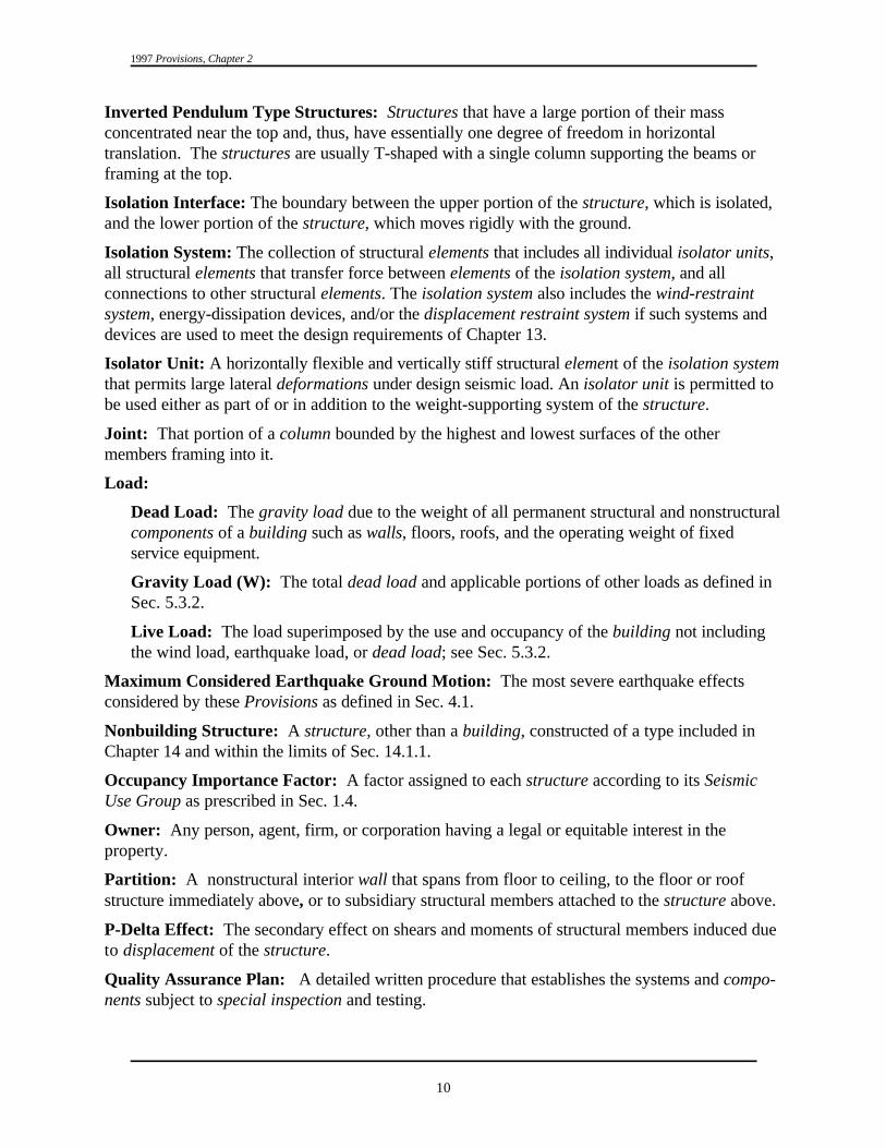
1997 Provisions, Chapter 2
10
Inverted Pendulum Type Structures: Structures that have a large portion of their massconcentrated near the top and, thus, have essentially one degree of freedom in horizontaltranslation. The structures are usually T-shaped with a single column supporting the beams orframing at the top.
Isolation Interface: The boundary between the upper portion of the structure, which is isolated,and the lower portion of the structure, which moves rigidly with the ground.
Isolation System: The collection of structural elements that includes all individual isolator units,all structural elements that transfer force between elements of the isolation system, and allconnections to other structural elements. The isolation system also includes the wind-restraintsystem, energy-dissipation devices, and/or the displacement restraint system if such systems anddevices are used to meet the design requirements of Chapter 13.
Isolator Unit: A horizontally flexible and vertically stiff structural element of the isolation systemthat permits large lateral deformations under design seismic load. An isolator unit is permitted tobe used either as part of or in addition to the weight-supporting system of the structure.
Joint: That portion of a column bounded by the highest and lowest surfaces of the othermembers framing into it.
Load:
Dead Load: The gravity load due to the weight of all permanent structural and nonstructuralcomponents of a building such as walls, floors, roofs, and the operating weight of fixedservice equipment.
Gravity Load (W): The total dead load and applicable portions of other loads as defined inSec. 5.3.2.
Live Load: The load superimposed by the use and occupancy of the building not includingthe wind load, earthquake load, or dead load; see Sec. 5.3.2.
Maximum Considered Earthquake Ground Motion: The most severe earthquake effectsconsidered by these Provisions as defined in Sec. 4.1.
Nonbuilding Structure: A structure, other than a building, constructed of a type included inChapter 14 and within the limits of Sec. 14.1.1.
Occupancy Importance Factor: A factor assigned to each structure according to its SeismicUse Group as prescribed in Sec. 1.4.
Owner: Any person, agent, firm, or corporation having a legal or equitable interest in theproperty.
Partition: A nonstructural interior wall that spans from floor to ceiling, to the floor or roofstructure immediately above, or to subsidiary structural members attached to the structure above.
P-Delta Effect: The secondary effect on shears and moments of structural members induced dueto displacement of the structure.
Quality Assurance Plan: A detailed written procedure that establishes the systems and compo-nents subject to special inspection and testing.

Glossary and Notations
11
FIGURE 2.1 Definition of story above grade.
Reference Resistance (D): The resistance (force or moment as appropriate) of a member orconnection computed at the reference end use conditions.
Registered Design Professional: An architect or engineer, registered or licensed to practiceprofessional architecture or engineering, as defined by the statutory requirements of theprofessional registrations laws of the state in which the project is to be constructed.
Roofing Unit: A unit of roofing material weighing more than 1 pound (0.5 kg).
Seismic Design Category: A classification assigned to a structure based on its Seismic UseGroup and the severity of the design earthquake ground motion at the site.
Seismic-Force-Resisting System: That part of the structural system that has been considered inthe design to provide the required resistance to the shear wall prescribed herein.
Seismic Forces: The assumed forces prescribed herein, related to the response of the structureto earthquake motions, to be used in the design of the structure and its components.
Seismic Response Coefficient: Coefficient C as determined from Sec. 5.3.2.1.s
Seismic Use Group: A classification assigned to a structure based on its use as defined in Sec.1.3.
Shallow Anchors: Anchors with embedment length-to-diameter ratios of less than 8.
Shear Panel: A floor, roof, or wall component sheathed to act as a shear wall or diaphragm.
Site Class: A classification assigned to a site based on the types of soils present and theirengineering properties as defined in Sec. 4.1.2.
Site Coefficients: The values of F and F indicated in Tables 1.4.2.3a and 1.4.2.3b, respectively.a v
Special Transverse Reinforcement: Reinforcement composed of spirals, closed stirrups, orhoops and supplementary cross-ties provided to restrain the concrete and qualify the portion ofthe component, where used, as a confined region.
Storage Racks: Include industrial pallet racks, movable shelf racks, and stacker racks made ofcold-formed or hot-rolled structural members. Does not include other types of racks such asdrive-in and drive-through racks, cantilever racks, portable racks, or racks made of materialsother than steel.
Story: The portion of a structure between the top to top of two successive finished floorsurfaces and, for the topmoststory, from the top of the floorfinish to the top of the roofstructural element.
Story Above Grade: Any storyhaving its finished floor surfaceentirely above grade, except that astory shall be considered as a storyabove grade where the finishedfloor surface of the storyimmediately above is more that 6
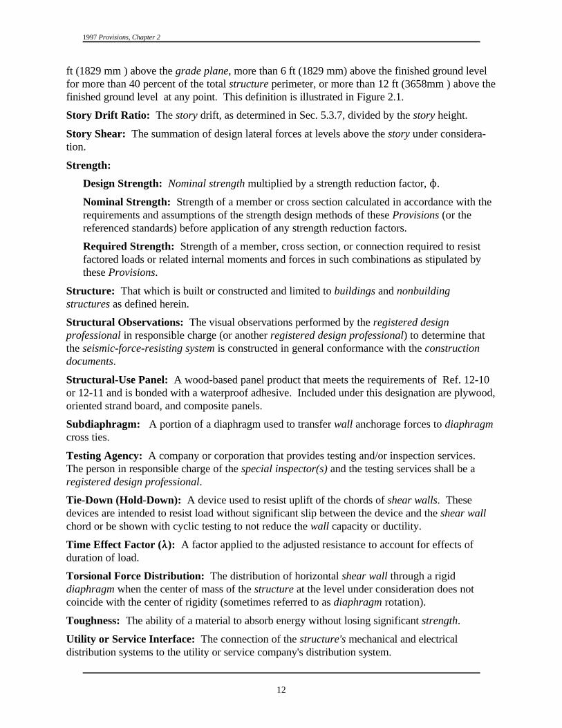
1997 Provisions, Chapter 2
12
ft (1829 mm ) above the grade plane, more than 6 ft (1829 mm) above the finished ground levelfor more than 40 percent of the total structure perimeter, or more than 12 ft (3658mm ) above thefinished ground level at any point. This definition is illustrated in Figure 2.1.
Story Drift Ratio: The story drift, as determined in Sec. 5.3.7, divided by the story height.
Story Shear: The summation of design lateral forces at levels above the story under considera-tion.
Strength:
Design Strength: Nominal strength multiplied by a strength reduction factor, N.
Nominal Strength: Strength of a member or cross section calculated in accordance with therequirements and assumptions of the strength design methods of these Provisions (or thereferenced standards) before application of any strength reduction factors.
Required Strength: Strength of a member, cross section, or connection required to resistfactored loads or related internal moments and forces in such combinations as stipulated bythese Provisions.
Structure: That which is built or constructed and limited to buildings and nonbuildingstructures as defined herein.
Structural Observations: The visual observations performed by the registered designprofessional in responsible charge (or another registered design professional) to determine thatthe seismic-force-resisting system is constructed in general conformance with the constructiondocuments.
Structural-Use Panel: A wood-based panel product that meets the requirements of Ref. 12-10or 12-11 and is bonded with a waterproof adhesive. Included under this designation are plywood,oriented strand board, and composite panels.
Subdiaphragm: A portion of a diaphragm used to transfer wall anchorage forces to diaphragmcross ties.
Testing Agency: A company or corporation that provides testing and/or inspection services. The person in responsible charge of the special inspector(s) and the testing services shall be aregistered design professional.
Tie-Down (Hold-Down): A device used to resist uplift of the chords of shear walls. Thesedevices are intended to resist load without significant slip between the device and the shear wallchord or be shown with cyclic testing to not reduce the wall capacity or ductility.
Time Effect Factor (88): A factor applied to the adjusted resistance to account for effects ofduration of load.
Torsional Force Distribution: The distribution of horizontal shear wall through a rigiddiaphragm when the center of mass of the structure at the level under consideration does notcoincide with the center of rigidity (sometimes referred to as diaphragm rotation).
Toughness: The ability of a material to absorb energy without losing significant strength.
Utility or Service Interface: The connection of the structure's mechanical and electricaldistribution systems to the utility or service company's distribution system.

Glossary and Notations
13
Veneers: Facings or ornamentation of brick, concrete, stone, tile, or similar materials attached toa backing.
Wall: A component that has a slope of 60 degrees or greater with the horizontal plane used toenclose or divide space.
Bearing Wall: An exterior or interior wall providing support for vertical loads.
Cripple Wall: A framed stud wall, less than 8 feet (2400 mm) in height, extending from thetop of the foundation to the underside of the lowest floor framing. Cripple walls can occur inboth engineered structures and conventional construction.
Light-Framed Wall: A wall with wood or steel studs.
Light-Framed Wood Shear Wall: A wall constructed with wood studs and sheathed withmaterial rated for shear resistance.
Nonbearing Wall: An exterior or interior wall that does not provide support for verticalloads other than its own weight or as permitted by the building code administered by theauthority having jurisdiction.
Nonstructural Wall: All walls other than bearing walls or shear walls.
Shear Wall (Vertical Diaphragm): A wall designed to resist lateral forces parallel to theplane of the wall (sometimes referred to as a vertical diaphragm).
Wall System, Bearing: A structural system with bearing walls providing support for all ormajor portions of the vertical loads. Shear walls or braced frames provide seismic-forceresistance.
Wind-Restraint System: The collection of structural elements that provides restraint of theseismic-isolated structure for wind loads. The wind-restraint system may be either an integralpart of isolator units or a separate device.
2.2 NOTATIONS:
A, B, C, D, E, F Site classes as defined in Sec. 4.1.2.
A Area (in. or mm ) of anchor bolt or stud in Chapters 6 and 11.b2 2
A Cross-sectional area (in. or mm ) of a component measured to the outside ofch2 2
the special lateral reinforcement.
A Net cross-sectional area of masonry (in. or mm ) in Chapter 11.n2 2
A The area of the load-carrying foundation (ft or m ).o2 2
A The area of an assumed failure surface taken as a pyramid in Eq. 9.2.4.1-3 orp
in Chapter 9.
A Projected area on the masonry surface of a right circular cone for anchor boltp
allowable shear and tension calculations (in. or mm ) in Chapter 11.2 2
A The area of an assumed failure surface taken as a pyramid in Eq. .2.4.1-3 or ins
Chapter 9.

1997 Provisions, Chapter 2
14
A Cross-sectional area of reinforcement (in. or mm ) in Chapters 6 and 11.s2 2
A Total cross-sectional area of hoop reinforcement (in. or mm ), includingsh2 2
supplementary cross-ties, having a spacing of s and crossing a section with ah
core dimension of h .c
A The area (in. or mm ) of the flat bottom of the truncated pyramid of ant2 2
assumed concrete failure surface in Sec. 9.2.4.1 or Eq. 9.2.4.1-3.
A Required area of leg (in. or mm ) of diagonal reinforcement.vd2 2
A The torsional amplification factor.x
a Length of compressive stress block (in. or mm) in Chapter 11.b
a The incremental factor related to P-delta effects in Sec. 5.3.6.2.d
a The component amplification factor as defined in Sec. 6.1.3.p
B Nominal axial strength of an anchor bolt (lb or N) in Chapter 11.a
B Numerical coefficient as set forth in Table 13.3.3.1 for effective dampingD
equal to $ .D
B Numerical coefficient as set forth in Table 13.3.3.1 for effective dampingM
equal to $ .M
B Nominal shear strength of an anchor bolt (lb or N) in Chapter 11.v
b The shortest plan dimension of the structure, in feet (mm), measuredperpendicular to d.
b Factored axial force on an anchor bolt (lb or N) in Chapter 11.a
b The shortest plan dimension of the structure, in feet (mm), measured perpen-dicular to d (Sec. 5.6).p
b Factored shear force on an anchor bolt (lb or N) in Chapter 11.v
b Web width (in. or mm) in Chapter 11.w
C Coefficient for upper limit on calculated period; see Table 5.3.3.u
C The deflection amplification factor as given in Table 5.2.2.d
C The seismic response coefficient (dimensionless) determined in Sec. 5.3.s
C The seismic response coefficient (dimensionless) determined in Sec. 5.5.2.1s
and 5.5.3.1.
C The modal seismic response coefficient (dimensionless) determined insm
Sec. 5.4.5.
C The building period coefficient in Sec. 5.3.3.1.T
C The vertical distribution factor as determined in Sec. 5.3.4.vx
c Distance from the neutral axis of a flexural member to the fiber of maximumcompressive strain (in. or mm).

Glossary and Notations
15
c Effective energy dissipation device damping coefficient (Eq. 13.3.2.1).eq
D Reference resistance in Chapter 12.
D The effect of dead load in Sec. 5.2.7 and Chapter 13.
D Adjusted resistance in Chapter 12.’
D Design displacement, in inches (mm), at the center of rigidity of the isolationD
system in the direction under consideration as prescribed by Eq. 13.3.3.1.
D Design displacement, in inches (mm), at the center of rigidity of the isolationD’
system in the direction under consideration, as prescribed by Eq. 13.4.2-1.
D Maximum displacement, in inches (mm), at the center of rigidity of theM
isolation system in the direction under consideration, as prescribed by Eq.13.3.3.3.
D Maximum displacement, in inches (mm), at the center of rigidity of theM'
isolation system in the direction under consideration, as prescribed by Eq.13.4.2-2 .
D Relative seismic displacement that the component must be designed top
accommodate as defined in Sec. 6.1.4.
D The total depth of the stratum in Eq. 5.5.2.1.2-4 (ft or m).s
D Total design displacement, in inches (mm), of an element of the isolationTD
system including both translational displacement at the center of rigidity andthe component of torsional displacement in the direction under considerationas prescribed by Eq. 13.3.3.5-1.
D Total maximum displacement, in inches (mm), of an element of the isolationTM
system including both translational displacement at the center of rigidity andthe component of torsional displacement in the direction under considerationas prescribed by Eq. 13.3.3.5-2.
d Overall depth of member (in. or mm) in Chapters 5 and 11.
d The longest plan dimension of the structure, in ft (mm), in Chapter 13.
d Diameter of reinforcement (in. or mm) in Chapter 11.b
d Distance from the anchor axis to the free edge (in. or mm) in Chapter 9.e
d The longest plan dimension of the structure, in feet (mm).p
E The effect of horizontal and vertical earthquake-induced forces (Sec. 5.2.7and Chapter 13).
E Energy dissipated in kip-inches (kN-mm), in an isolator unit during a fullloop
cycle of reversible load over a test displacement range from ) to ∆ , as+ -
measured by the area enclosed by the loop of the force-deflection curve.
E Chord modulus of elasticity of masonry (psi or MPa) in Chapter 11.m
E Modulus of elasticity of reinforcement (psi or MPa) in Chapter 11.s

f )c
f )m
1997 Provisions, Chapter 2
16
E Modulus of rigidity of masonry (psi or MPa) in Chapter 11.v
e The actual eccentricity, in feet (mm), measured in plan between the center ofmass of the structure above the isolation interface and the center of rigidity ofthe isolation system, plus accidental eccentricity, in feet (mm), taken as 5percent of the maximum building dimension perpendicular to the direction offorce under consideration.
F Acceleration-based site coefficient (at 0.3 sec period).a
F Maximum negative force in an isolator unit during a single cycle of prototype-
testing at a displacement amplitude of ) .-
F Positive force in kips (kN) in an isolator unit during a single cycle of+
prototype testing at a displacement amplitude of ) .+
F , F , F The portion of the seismic base shear, V, induced at Level I, n, or x, respec-i n x
tively, as determined in Sec. 5.3.4 (kip or kN).
F The seismic design force center of gravity and distributed relative to thep
component's weight distribution as determined in Sec. 6.1.3.
F The induced seismic force on connections and anchorages as determined inp
Sec. 5.2.5.1.
F Specified ultimate tensile strength (psi or MPa) of an anchor (Sec. 9.2.4).u
F Velocity-based site coefficient (at 1.0 sec period).v
F Total force distributed over the height of the structure above the isolationx
interface as prescribed by Eq. 13.3.5.
F The portion of the seismic base shear, V , induced at Level x as determined inxm m
Sec. 5.4.6 (kip or kN).
Specified compressive strength of concrete used in design.
Specified compressive strength of masonry (psi or MPa) at the age of 28 daysunless a different age is specified, Chapter 11.
f Modulus of rupture of masonry (psi or MPa) in Chapter 11.r
fN Ultimate tensile strength (psi or MPa) of the bolt, stud, or insert leg wires. s
For A307 bolts or A108 studs, is permitted to be assumed to be 60,000 psi(415 MPa).
f Specified yield strength of reinforcement (psi or MPa).y
f Specified yield stress of the special lateral reinforcement (psi or kPa).yh
G (v /g = the average shear modulus for the soils beneath the foundation ats²
large strain levels (psf or Pa).
G (v /g = = the average shear modulus for the soils beneath the foundation ato so²
small strain levels (psf or Pa).
g Acceleration of gravity in in./sec (mm/s ).2 2
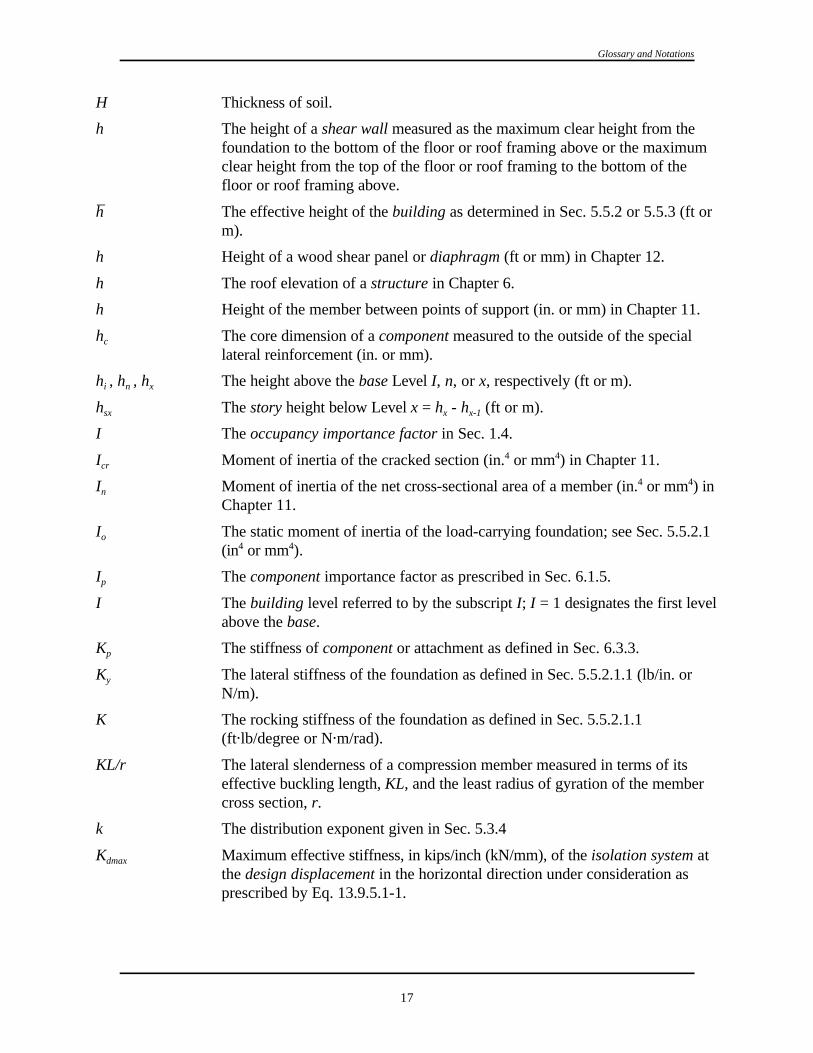
Glossary and Notations
17
H Thickness of soil.
h The height of a shear wall measured as the maximum clear height from thefoundation to the bottom of the floor or roof framing above or the maximumclear height from the top of the floor or roof framing to the bottom of thefloor or roof framing above.
h The effective height of the building as determined in Sec. 5.5.2 or 5.5.3 (ft orm).
h Height of a wood shear panel or diaphragm (ft or mm) in Chapter 12.
h The roof elevation of a structure in Chapter 6.
h Height of the member between points of support (in. or mm) in Chapter 11.
h The core dimension of a component measured to the outside of the specialc
lateral reinforcement (in. or mm).
h , h , h The height above the base Level I, n, or x, respectively (ft or m).i n x
h The story height below Level x = h - h (ft or m).sx x x-1
I The occupancy importance factor in Sec. 1.4.
I Moment of inertia of the cracked section (in. or mm ) in Chapter 11.cr4 4
I Moment of inertia of the net cross-sectional area of a member (in. or mm ) inn4 4
Chapter 11.
I The static moment of inertia of the load-carrying foundation; see Sec. 5.5.2.1o
(in or mm ).4 4
I The component importance factor as prescribed in Sec. 6.1.5.p
I The building level referred to by the subscript I; I = 1 designates the first levelabove the base.
K The stiffness of component or attachment as defined in Sec. 6.3.3.p
K The lateral stiffness of the foundation as defined in Sec. 5.5.2.1.1 (lb/in. ory
N/m).
K The rocking stiffness of the foundation as defined in Sec. 5.5.2.1.12
(ft"lb/degree or N"m/rad).
KL/r The lateral slenderness of a compression member measured in terms of itseffective buckling length, KL, and the least radius of gyration of the membercross section, r.
k The distribution exponent given in Sec. 5.3.4
K Maximum effective stiffness, in kips/inch (kN/mm), of the isolation system atdmax
the design displacement in the horizontal direction under consideration asprescribed by Eq. 13.9.5.1-1.

1997 Provisions, Chapter 2
18
K Minimum effective stiffness, in kips/inch (kN/mm), of the isolation system atDmin
the design displacement in the horizontal direction under consideration asprescribed by Eq. 13.9.5.1-2.
K Maximum effective stiffness, in kips/inch (kN/mm), of the isolation system atmax
the maximum displacement in the horizontal direction under consideration asprescribed by Eq. 13.9.5.1-3.
K Minimum effective stiffness, in kips/inch (kN/mm), of the isolation system atMin
the maximum displacement in the horizontal direction under consideration, asprescribed by Eq. 13.9.5.1-4.
k Effective stiffness of an isolator unit, as prescribed by Eq. 13.9.3-1.eff
k The stiffness of the building as determined in Sec. 5.5.2.1.1 (lb/ft or N/m).
L The overall length of the building (ft or m) at the base in the direction beinganalyzed.
L Length of bracing member (in. or mm) in Chapter 8.
L Length of coupling beam between coupled shear walls in Chapter 11 (in. ormm).
L The effect of live load in Chapter 13.
L The overall length of the side of the foundation in the direction beingo
analyzed, Sec. 5.5.2.1.2 (ft or m).
l The dimension of a diaphragm perpendicular to the direction of application offorce. For open-front structures, l is the length from the edge of thediaphragm at the open front to the vertical resisting elements parallel to thedirection of the applied force. For a cantilevered diaphragm, l is the length ofthe cantilever.
R Effective embedment length of anchor bolt (in. or mm) in Chapter 11.b
R Anchor bolt edge distance (in. or mm) in Chapter 11.be
R Development length (in. or mm) in Chapter 11.d
R Equivalent development length for a standard hook (in. or mm) in Chapter 11.dh
R Minimum lap splice length (in. or mm) in Chapter 11.ld
M Moment on a masonry section due to unfactored loads (in."lb or N"mm) inChapter 11.
M Maximum moment in a member at stage deflection is computed (in."lb ora
N"mm) in Chapter 11.
M Cracking moment strength of the masonry (in."lb or N"mm) in the Chapter 11.cr
M Design moment strength (in."lb or N"mm) in Chapter 11.d
M The foundation overturning design moment as defined in Sec. 5.3.6 (ft"kip orf
kN"m).

Glossary and Notations
19
M , M The overturning moment at the foundation-soil interface as determined ino o1
Sec. 5.5.2.3 and 5.5.3.2 (ft"lb or N"m).
M Unfactored ultimate moment capacity at balanced strain conditions (Sec.nb
7.5.3.4).
M The torsional moment resulting from the location of the building masses,t
Sec. 5.3.5.1 (ft"kip or kN"m).
M The accidental torsional moment as determined in Sec. 5.3.5.1 (ft"kip orta
kN"m).
M Required flexural strength due to factored loads (in."lb or N"mm) in Chapteru
11.
M , M Nominal moment strength at the ends of the coupling beam (in."lb or N"mm)1 2
in Chapter 11.
M The building overturning design moment at Level x as defined in Sec. 5.3.6 orx
Sec. 5.4.10 (ft"kip or kN"m).
m A subscript denoting the mode of vibration under consideration; i.e., m = 1 forthe fundamental mode.
N Number of stories, Sec. 5.3.3.1.
N Standard penetration resistance, ASTM D1536-84.
N Average field standard penetration test for the top 100 ft (30 m); see Sec. 4.1.2.1.
N Average standard penetration for cohesionless soil layers for the top 100 ftch
(30 m); see Sec. 4.1.2.1.
N Force acting normal to shear surface (lb or N) in Chapter 11.v
n Designates the level that is uppermost in the main portion of the building.
n Number of anchors (Sec. 9.2.4).
P Axial load on a masonry section due to unfactored loads (lb or N) in Chapter11.
P Design tensile strength governed by concrete failure of anchor bolts (Sec.c
9.2.4).
P Required axial strength on a column resulting from application of dead load,D
D, in Chapter 5 (kip or kN).
P Required axial strength on a column resulting from application of theE
amplified earthquake load, E , in Chapter 5 (kip or kN).N
P Required axial strength on a column resulting from application of live load, L,L
in Chapter 5 (kip or kN).
P Nominal axial load strength (lb or N) in Chapter 8.n

1997 Provisions, Chapter 2
20
P The algebraic sum of the shear wall and the minimum gravity loads on then
joint surface acting simultaneously with the shear (lb or N).
P Nominal axial load strength (lb or N) in Chapter 11.n
P Design tensile strength governed by steel of anchor bolts in Chapter 9.s
P Required axial load (lb or N) in Chapter 11.u
P Tensile strength required due to factored loads (lb or N) in Chapter 9.u
P Required axial strength on a brace (kip or kN) in Chapter 8.u*
P The total unfactored vertical design load at and above Level x (kip or kN).x
PI Plasticity index, ASTM D4318-93.
Q The effect of horizontal building forces (kip or kN); see Sec. 5.2.6.E
Q The load equivalent to the effect of the horizontal and vertical shear strengthV
of the vertical segment, Appendix to Chapter 8.
R The response modification coefficient as given in Table 5.2.2.
R Numerical coefficient related to the type of lateral-force-resisting systemI
above the isolation system as set forth in Table 13.3.4.2 for seismicallyisolated structures.
R The component response modification factor as defined in Sec. 6.1.3.p
r A characteristic length of the foundation as defined in Sec. 5.5.2.1 (ft or m).
r Radius of gyration (in. or mm) in Chapter 11.
r The characteristic foundation length defined by Eq. 5.5.2.1.2-2 (ft or m).a
r The characteristic foundation length as defined by Eq. 5.5.2.1.2-3 (ft or m).m
r The ratio of the design story shear resisted by the most heavily loaded singlex
element in the story, in direction x, to the total story shear.
S Section modulus based on net cross sectional area of a wall (in. or mm ) in3 3
Chapter 11.
S The mapped maximum considered earthquake, 5% damped, spectral response1
acceleration at a period of 1 second as defined in Sec. 4.1.1.
S The design, 5% damped, spectral response acceleration at a period of oneD1
second as defined in Sec. 4.1.2.
S The design, 5% damped, spectral response acceleration at short periods asDS
defined in Sec. 4.1.2.
S The maximum considered earthquake, 5 percent damped, spectral responseM1
acceleration at a period of 1 second adjusted for site class effects as defined inSec. 4.1.2.

Glossary and Notations
21
S The maximum considered earthquake, 5% damped, spectral responseMS
acceleration at short periods adjusted for site class effects as defined in Sec.4.1.2.
S The mapped maximum considered earthquake, 5% damped, spectral responseS
acceleration at short periods as defined in Sec. 4.1.2.
S Probable strength of precast element connectors (Sec. 9A.5.1).pr
s Average undrained shear strength in top 100 ft (30.5 m); see Sec. 4.1.2.1,u
ASTM D2166-91 or ASTM D2850-87.
s Spacing of special lateral reinforcement (in. or mm).h
T The fundamental period (sec) of the building as determined in Sec. 5.3.3 orthe modal period (sec) of the building modified as appropriate to account forthe effective stiffness of the energy dissipation system (Sec. 13.3.2.1).
T, T The effective fundamental period (sec) of the building as determined in1
Sec. 5.5.2.1.1 and 5.5.3.1.
T The approximate fundamental period (sec) of the building as determined ina
Sec. 5.3.3.1.
T Effective period, in seconds (sec), of the seismically isolated structure at theD
design displacement in the direction under consideration as prescribed by Eq.13.3.3.2.
T The fundamental period (sec) of the component and its attachment(s) asp
defined in Sec. 6.3.3.
T 0.2S /S .0 D1 DS
T S /S .S D1 DS
T Effective period, in seconds (sec), of the seismically isolated structure at theM
maximum displacement in the direction under consideration as prescribed byEq. 13.3.3.4.
T The modal period of vibration (sec) of the m mode of the building as deter-mth
mined in Sec. 5.4.5.
T Net tension in steel cable due to dead load, prestress, live load, and seismic4
load (Sec. 8.5).
t Specified wall thickness dimension or least lateral dimension of a column (in.or mm) in Chapter 11.
t Thickness of masonry cover over reinforcing bars measured from the surfacec
of the masonry to the surface of the reinforcing bars (in. or mm) in Chapter11.
V The total design lateral force or shear at the base (kip or kN).
V Shear on a masonry section due to unfactored loads (lb or N) in Chapter 11.

1997 Provisions, Chapter 2
22
V The total lateral seismic design force or shear on elements of the isolationb
system or elements below the isolation system as prescribed by Eq. 13.3.4.1.
V Shear strength provided by masonry (lb or N) in Chapter 11.m
V Nominal shear strength (lb or N) in Chapter 11.n
V The total lateral seismic design force or shear on elements above the isolations
system as prescribed by Eq. 13.3.4.2.
V Shear strength provided by shear reinforcement (lb or N) in Chapters 6 ands
11.
V The design value of the seismic base shear as determined in Sec. 5.4.8 (kip ort
N).
V Required shear strength (lb or N) due to factored loads in Chapters 6 and 11.u
V The seismic design shear in Story x as determined in Sec. 5.3.5 or Sec. 5.4.8x
(kip or kN).
V The portion of the seismic base shear, V, contributed by the fundamental¹
mode, Sec. 5.5.3 (kip or kN).
)V The reduction in V as determined in Sec. 5.5.2 (kip or kN).
)V The reduction in V as determined in Sec. 5.5.3 (kip or kN).¹ ¹
v The average shear wave velocity for the soils beneath the foundation at larges
strain levels, Sec. 5.5.2 (ft/s or m/s).
v Average shear wave velocity in top 100 ft (30 m); see Sec. 4.1.2.1.s
v The average shear wave velocity for the soils beneath the foundation at smallso
strain levels, Sec. 5.5.2 (ft/s or m/s).
W The total gravity load of the building as defined in Sec. 5.3.2 (kip or kN). For calculation of seismic-isolated building period, W is the total seismic deadload weight of the building as defined in Sec. 5.5.2 and 5.5.3 (kip or kN).
W The effective gravity load of the building as defined in Sec. 5.5.2 and 5.5.3(kip or kN).
W The energy dissipated per cycle at the story displacement for the designD
earthquake (Sec. 13.3.2).
W The effective modal gravity load determined in accordance with Eq. 5.4.5-1m
(kip or kN).
W Component operating weight (lb or N).p
w Width of a wood shear panel or diaphragm in Chapter 9 (ft or mm).
w Moisture content (in percent), ASTM D2216-92.
w The dimension of a diaphragm or shear wall in the direction of application offorce.

Glossary and Notations
23
w , w The portion of the total gravity load, W, located or assigned to Level I or xi x
(kip or kN).
z The level under consideration; x = 1 designates the first level above the base.
x Elevation in structure of a component addressed by Chapter 6.
y Elevation difference between points of attachment in Chapter 6.
y The distance, in feet (mm), between the center of rigidity of the isolationsystem rigidity and the element of interest measured perpendicular to thedirection of seismic loading under consideration Chapter 13).
" The relative weight density of the structure and the soil as determined inSec. 5.5.2.1.
" Angle between diagonal reinforcement and longitudinal axis of the member(degree or rad).
$ Ratio of shear demand to shear capacity for the story between Level x and x -1.
$ The fraction of critical damping for the coupled structure-foundation system,determined in Sec. 5.5.2.1.
$ Effective damping of the isolation system at the design displacement asD
prescribed by Eq. 13.9.5.2-1.
$ Effective damping of the isolation system at the maximum displacement asM
prescribed by Eq. 13.9.5.2-2.
$ The foundation damping factor as specified in Sec. 5.5.2.1.o
$ Effective damping of the isolation system as prescribed by Eq. 13.9.3-2.eff
( Lightweight concrete factor (Sec. 9.2.4.1).
( The average unit weight of soil (lb/ft or kg/m ).3 3
) The design story drift as determined in Sec. 5.3.7.1 (in. or mm).
) The displacement of the dissipation device and device supports across thestory (Sec. 13.3.2.1).
) Suspended ceiling lateral deflection (calculated) in Sec. 6.2.6.4.2 (in. or mm).
) The allowable story drift as specified in Sec. 5.2.7 (in. or mm).a
) The design modal story drift determined in Sec. 5.4.6 (in. or mm)m
) Relative displacement that the component must be designed to accommodatep
as defined in Sec. 6.2.2.2 or 6.3.2.2.
* Deflection based on cracked section properties (in. or mm) in Chapter 11.cr
) Maximum positive displacement of an isolator unit during each cycle of+
prototype testing.

1997 Provisions, Chapter 2
24
) Maximum negative displacement of an isolator unit during each cycle of-
prototype testing.
* The maximum displacement at Level x (in. or mm).max
* The average of the displacements at the extreme points of the structure atavg
Level x (in. or mm).
* The deflection of Level x at the center of the mass at and above Level x, Eq.x
5.3.7.1 (in. or mm).
* The deflection of Level x at the center of the mass at and above Level x deter-xe
mined by an elastic analysis, Sec. 5.3.7.1 (in. or mm).
* The modal deflection of Level x at the center of the mass at and above Level xxem
determined by an elastic analysis, Sec. 5.4.6 (in. or mm).
* , * The modal deflection of Level x at the center of the mass at and above Level xxm xm
as determined by Eq. 5.4.6-3 and 5.5.3.2-1 (in. or mm).
* , * The deflection of Level x at the center of the mass at and above Level x, Eq.x x1
5.5.2.3 and 5.5.3.2-1 (in. or mm).
0 Maximum usable compressive strain of masonry (in./in. or mm/mm) inmu
Chapter 11.
2 The stability coefficient for P-delta effects as determined in Sec. 5.3.6.2.
J The overturning moment reduction factor (Sec. 5.3.6).
D A reliability coefficient based on the extent of structural redundance present ina building as defined in Sec. 5.2.7.
D Ratio of the area of reinforcement to the net cross sectional area of masonryin a plane perpendicular to the reinforcement in Chapter 11.
D Reinforcement ratio producing balanced strain conditions in Chapter 11.b
D Ratio of the area of shear reinforcement to the cross sectional area of masonryh
in a plane perpendicular to the reinforcement in Chapter 11.
D Spiral reinforcement ratio for precast prestressed piles in Sec. 7.5.3.4.s
D Ratio of vertical or horizontal reinforcement in walls (Ref. 7-2).v
D A reliability coefficient based on the extent of structural redundancy present inx
the seismic-force-resisting system of a building in the x direction.
8 Time effect factor.
N The capacity reduction factor.
N Strength reduction factor in Chapters 6 and 11.
N Resistance factor for steel in Chapter 8 and wood in Chapter 12.
N The displacement amplitude at the i level of the building for the fixed baseimth
condition when vibrating in its m mode, Sec. 5.4.5.th
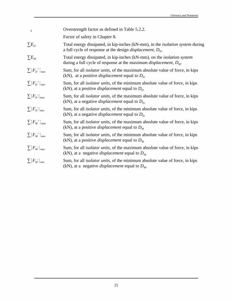
Glossary and Notations
25
S Overstrength factor as defined in Table 5.2.2.0
S Factor of safety in Chapter 8.
3E Total energy dissipated, in kip-inches (kN-mm), in the isolation system duringD
a full cycle of response at the design displacement, D .D
3E Total energy dissipated, in kip-inches (kN-mm), on the isolation systemM
during a full cycle of response at the maximum displacement, D .M
3*F * Sum, for all isolator units, of the maximum absolute value of force, in kipsD max+
(kN), at a positive displacement equal to DD.
3*F * Sum, for all isolator units, of the minimum absolute value of force, in kipsD min+
(kN), at a positive displacement equal to DD.
3*F * Sum, for all isolator units, of the maximum absolute value of force, in kipsD max-
(kN), at a negative displacement equal to DD.
3*F * Sum, for all isolator units, of the minimum absolute value of force, in kipsD min-
(kN), at a negative displacement equal to DD.
3*F * Sum, for all isolator units, of the maximum absolute value of force, in kipsM max+
(kN), at a positive displacement equal to DM.
3*F * Sum, for all isolator units, of the minimum absolute value of force, in kipsM min+
(kN), at a positive displacement equal to DM.
3*F * Sum, for all isolator units, of the maximum absolute value of force, in kipsM max-
(kN), at a negative displacement equal to DM.
3*F * Sum, for all isolator units, of the minimum absolute value of force, in kipsM min-
(kN), at a negative displacement equal to D .M
26
Chapter 3
QUALITY ASSURANCE
3.1 SCOPE: This chapter provides minimum requirements for quality assurance for seismic-force-resisting systems and designated seismic systems. These requirements supplement thetesting and inspection requirements contained in the reference standards given in Chapters 8through 14.
3.2 QUALITY ASSURANCE: A quality assurance plan shall be submitted to the authorityhaving jurisdiction. A quality assurance plan, special inspection(s), and testing as set forth inthis chapter shall be provided for the following:
1. The seismic-force-resisting systems in structures assigned to Seismic Design Categories C,D, E, and F.
2. Designated seismic systems in structures assigned to Seismic Design Categories D, E, and Fthat are required in Table 6.1.7.
Exception: Structures that comply with the following criteria are exempt from thepreparation of a quality assurance plan but those structures are not exempt from specialinspection(s) or testing requirements:
1. The structure is constructed of light wood framing or light gauge cold-formed steelframing, S does not exceed 0.50g, the height of the structure does not exceed 35DS
feet above grade, and the structure meets the requirements in Items 3 and 4 below
or
2. The structure is constructed using a reinforced masonry structural system orreinforced concrete structural system, S does not exceed 0.50g, the height of theDS
structure does not exceed 25 feet above grade, and the structure meets therequirements in Items 3 and 4 below
3. The structure is classified as Seismic Use Group I
4. The structure does not have any of the following plan irregularities as defined inTable 5.2.3.2 or any of the following vertical irregularities as defined in Table5.2.3.3:
a. Torsional irregularity,b. Extreme torsional irregularity,c. Nonparallel systems,

1997 Provisions, Chapter 3
27
d. Stiffness irregularity -- soft story,e. Stiffness irregularity -- extreme soft story,f. Discontinuity in capacity -- weak story.
3.2.1 Details of Quality Assurance Plan: The registered design professional in responsiblecharge of the design of a seismic-force-resisting system and a designated seismic system shall beresponsible for the portion of the quality assurance plan applicable to that system. The qualityassurance plan shall include:
1. The seismic-force-resisting systems and designated seismic systems in accordance with thischapter that are subject to quality assurance.
2. The special inspections and testing to be provided as required by these Provisions and thereference standards in Chapters 4 through 14.
3. The type and frequency of testing.
4. The type and frequency of special inspections.
5. The frequency and distribution of testing and special inspection reports.
6. The structural observations to be performed.
7. The frequency and distribution of structural observation reports.
3.2.2 Contractor Responsibility: Each contractor responsible for the construction of aseismic–force–resisting system, designated seismic system, or component listed in the qualityassurance plan shall submit a written contractor's statement of responsibility to the authorityhaving jurisdiction and to the owner prior to the commencement of work on the system orcomponent. The contractor's statement of responsibility shall contain the following:
1. Acknowledgment of awareness of the special requirements contained in the quality assuranceplan;
2. Acknowledgment that control will be exercised to obtain conformance with the constructiondocuments approved by the authority having jurisdiction;
3. Procedures for exercising control within the contractor's organization, the method andfrequency of reporting, and the distribution of the reports; and
4. Identification and qualifications of the person(s) exercising such control and their position(s)in the organization.
3.3 SPECIAL INSPECTION: The owner shall employ a special inspector(s) to observe theconstruction for compliance with the following:
3.3.1 Piers, Piles, Caissons: Continuous special inspection during driving of piles andplacement of concrete in piers, piles, and caissons. Periodic special inspection duringconstruction of drilled piles, piers, and caissons including the placement of reinforcing steel.
3.3.2 Reinforcing Steel:
3.3.2.1: Periodic special inspection during and upon completion of the placement of reinforcingsteel in intermediate moment frames, in special moment frames, and in shear walls.

Quality Assurance
28
3.3.2.2: Continuous special inspection during the welding of reinforcing steel resisting flexuraland axial forces in intermediate moment frames and special moment frames, in boundarymembers of concrete shear walls, and during welding of shear reinforcement.
3.3.3 Structural Concrete: Periodic special inspection during and on completion of theplacement of concrete in intermediate moment frames, in special moment frames, and inboundary members of shear walls.
3.3.4 Prestressed Concrete: Periodic special inspection during the placement and aftercompletion of placement of prestressing steel and continuous special inspection is required duringall stressing and grouting operations and during the placement of concrete.
3.3.5 Structural Masonry:
3.3.5.1: Periodic special inspection during the preparation of mortar, the laying of masonryunits, and placement of reinforcement and prior to placement of grout
3.3.5.2: Continuous special inspection during the welding of reinforcement, grouting, consolida-tion, reconsolidation and placement of bent-bar anchors as required by Sec. 11.3.12.2.
3.3.6 Structural Steel:
3.3.6.1: Continuous special inspection for all structural welding.
Exception: Periodic special inspection is permitted for single-pass fillet or resistancewelds and welds loaded to less than 50 percent of their design strength provided thequalifications of the welder and the welding electrodes are inspected at the beginning ofthe work and all welds are inspected for compliance with the approved constructiondocuments at the completion of welding.
3.3.6.2: Periodic special inspection in accordance with Ref. 8-1 or 8-2 for installation andtightening of fully tensioned high-strength bolts in slip-critical connections and in connectionssubject to direct tension. Bolts in connections identified as not being slip-critical or subject todirect tension need not be inspected for bolt tension other than to ensure that the plies of theconnected elements have been brought into snug contact.
3.3.7 Structural Wood:
3.3.7.1: Continuous special inspection during all field gluing operations of elements of theseismic-force-resisting system.
3.3.7.2: Periodic special inspections for nailing, bolting, anchoring, and other fastening ofcomponents within the seismic-force-resisting system including drag struts, braces, and tie-downs.
3.3.8 Cold–Formed Steel Framing:
3.3.8.1 Periodic special inspections during all welding operations of elements of theseismic–force–resisting system.

1997 Provisions, Chapter 3
29
3.3.8.2 Periodic special inspections for screw attachment, bolting, anchoring, and other fasteningof components within the seismic–force–resisting system, including struts, braces, andhold–downs.
3.3.9 Architectural Components: Special inspection for architectural components shall be asfollows:
1. Periodic special inspection during the erection and fastening of exterior cladding, interior andexterior nonloadbearing walls, and veneer in Seismic Design Categories D, E, and F and
Exceptions:
a. Structures 30 feet (9 m) or less in height andb. Cladding and veneer weighing 5 lb/ft (240 kg/m ) or less.2 2
2. Periodic special inspection during the anchorage of access floors, suspended ceilings, andstorage racks 8 feet (2.4 m) or greater in height in Seismic Design Categories D, E, and F.
3.3.10 Mechanical and Electrical Components: Special inspection for mechanical andelectrical components shall be as follows:
1. Periodic special inspection during the anchorage of electrical equipment for emergency orstandby power systems in Seismic Design Categories C, D, E, and F;
2. Periodic special inspection during the installation of anchorage of all other electricalequipment in Seismic Design Categories E and F;
3. Periodic special inspection during installation for flammable, combustible, or highly toxicpiping systems and their associated mechanical units in Seismic Design Categories C, D, E,and F; and
4. Periodic special inspection during the installation of HVAC ductwork that will containhazardous materials in Seismic Design Categories C, D, E, and F.
3.3.11 Seismic Isolation System: Periodic special inspection during the fabrication andinstallation of isolator units and energy dissipation devices if used as part of the seismic isolationsystem.
3.4 TESTING: The special inspector(s) shall be responsible for verifying that the testingrequirements are performed by an approved testing agency for compliance with the following:
3.4.1 Reinforcing and Prestressing Steel: Special testing of reinforcing and prestressing steelshall be as follows:
3.4.1.1: Examine certified mill test reports for each shipment of reinforcing steel used to resistflexural and axial forces in reinforced concrete intermediate frames, special moment frames, andboundary members of reinforced concrete shear walls or reinforced masonry shear walls anddetermine conformance with the construction documents.
3.4.1.2: Where ASTM A615 reinforcing steel is used to resist earthquake-induced flexural andaxial forces in special moment frames and in wall boundary elements of shear walls in structures

Quality Assurance
30
of Seismic Design Categories D, E, and F, verify that the requirements of Sec. 21.2.5.1 of Ref. 9-1 have been satisfied.
3.4.1.3: Where ASTM A615 reinforcing steel is to be welded, verify that chemical tests havebeen performed to determine weldability in accordance with Sec. 3.5.2 of Ref. 9-1.
3.4.2 Structural Concrete: Samples of structural concrete shall be obtained at the project siteand tested in accordance with requirements of Ref. 9-1
3.4.3 Structural Masonry: Quality assurance testing of structural masonry shall be inaccordance with the requirements of Ref. 11-1.
3.4.4 Structural Steel: The testing needed to establish that the construction is in conformancewith these Provisions shall be included in a quality assurance plan. The minimum testingcontained in the quality assurance plan shall be as required in Ref. 8-3 and the followingrequirements:
3.4.4.1 Base Metal Testing: Base metal thicker than 1.5 in. (38 mm), when subject to through-thickness weld shrinkage strains, shall be ultrasonically tested for discontinuities behind andadjacent to such welds after joint completion. Any material discontinuities shall be accepted orrejected on the basis of ASTM A435, Specification for Straight Beam Ultrasound Examinationof Steel Plates, or ASTM A898, Specification for Straight Beam Ultrasound Examination forRolled Steel Shapes, (Level 1 Criteria) and criteria as established by the registered design profes-sional(s) in responsible charge and the construction documents.
3.4.5 Mechanical and Electrical Equipment: As required to ensure compliance with theseismic design requirements herein, the registered design professional in responsible charge shallclearly state the applicable requirements on the construction documents. Each manufacturer ofdesignated seismic system components shall test or analyze the component and its mountingsystem or anchorage as required and shall submit evidence of compliance for review andacceptance by the registered design professional in responsible charge of the designated seismicsystem and for approval by the authority having jurisdiction. The evidence of compliance shall beby actual test on a shake table, by three-dimensional shock tests, by an analytical method usingdynamic characteristics and forces, by the use of experience data (i.e., historical datademonstrating acceptable seismic performance), or by more rigorous analysis providing forequivalent safety. The special inspector shall examine the designated seismic system and shalldetermine whether the anchorages and label conform with the evidence of compliance.
3.4.6 Seismically Isolated Structures: For required system tests, see Sec. 13.9.
3.5 STRUCTURAL OBSERVATIONS: Structural observations shall be provided for thosestructures included in Seismic Design Categories D, E, and F when one or more of the followingconditions exist:
1. The structure is included in Seismic Use Group II or Seismic Use Group III or
2. The height of the structure is greater than 75 feet above the base or
3. The structure is in Seismic Design Category E or F and Seismic Use Group I and is greaterthan two stories in height.

1997 Provisions, Chapter 3
31
Observed deficiencies shall be reported in writing to the owner and the authority havingjurisdiction.
3.6 REPORTING AND COMPLIANCE PROCEDURES: Each special inspector shallfurnish to the authority having jurisdiction, registered design professional in responsible charge,the owner, the persons preparing the quality assurance plan, and the contractor copies of regularprogress reports of the inspector's observations, noting therein any uncorrected deficiencies andcorrections made to previously reported deficiencies. All deficiencies shall be brought to theimmediate attention of the contractor for correction.
At completion of construction, each special inspector shall submit a final report to the authorityhaving jurisdiction certifying that all inspected work was completed substantially in accordancewith the approved construction documents. Work not in compliance with the approvedconstruction documents shall be described in the final report.
At completion of construction, the contractor shall submit a final report to the authority havingjurisdiction certifying that all construction work incorporated into the seismic-force-resistingsystem and other designated seismic systems was constructed substantially in accordance with theapproved construction documents and applicable workmanship requirements. Work not incompliance with the approved construction documents shall be described in the final report.
The contractor shall correct all deficiencies as required.

32
Chapter 4
GROUND MOTION
4.1 PROCEDURES FOR DETERMINING MAXIMUM CONSIDERED EARTHQUAKEAND DESIGN EARTHQUAKE GROUND MOTION ACCELERATIONS ANDRESPONSE SPECTRA: Ground motion accelerations, represented by response spectra andcoefficients derived from these spectra, shall be determined in accordance with the generalprocedure of Sec. 4.1.2 or the site-specific procedure of Sec. 4.1.3. The general procedure inwhich spectral response acceleration parameters for the maximum considered earthquake groundmotions are derived using Maps 1 through 24, modified by site coefficients to include local siteeffects and scaled to design values, are permitted to be used for any structure except asspecifically indicated in these Provisions. The site-specific procedure also is permitted to be usedfor any structure and shall be used where specifically required by these Provisions.
4.1.1 Maximum Considered Earthquake Ground Motions: The maximum consideredearthquake ground motions shall be as represented by the mapped spectral response accelerationat short periods, S , and at 1 second, S , obtained from Maps 1 through 24 of these Provisions,S 1
respectively, and adjusted for Site Class effects using the site coefficients of Sec. 4.1.2.4. When asite-specific procedure is used, maximum considered earthquake ground motion shall bedetermined in accordance with Sec. 4.1.3.
4.1.2 General Procedure for Determining Maximum Considered Earthquake and DesignSpectral Response Accelerations: The mapped maximum considered earthquake spectralresponse acceleration at short periods (S ) and at 1 second (S ) shall be determined respectivelyS 1
from Spectral Acceleration Maps 1 through 24.
For structures located within those regions of the maps having values of the short period spectralresponse acceleration, S , less than or equal to 0.15g and values of the 1 second period spectralS
response acceleration, S , less than or equal to 0.04g, accelerations need not be determined. Such1
structures are permitted to be directly categorized as Seismic Design Category A in accordancewith Sec. 4.2.1.
For all other structures, the Site Class shall be determined in accordance with Sec. 4.1.2.1. Themaximum considered earthquake spectral response accelerations adjusted for Site Class effects,S and S shall be determined in accordance with Sec. 4.1.2.4 and the design spectral responseMS M1
accelerations, S and S , shall be determined in accordance with Sec. 4.1.2.5. The generalDS D1
response spectrum, when required by these Provisions, shall be determined in accordance withSec. 4.1.2.6.
4.1.2.1 Site Class Definitions: For all structures located within those regions of the mapshaving values of the short period spectral response acceleration, S , greater than 0.15g or valuesS
of the 1 second period spectral response acceleration, S , greater than 0.04g, the site shall be1
classified as one of the following classes:

1997 Provisions, Chapter 4
33
A Hard rock with measured shear wave velocity, v > 5,000 ft/sec (1500 m/s)s
B Rock with 2,500 ft/sec < v # 5,000 ft/sec (760 m/s < v # 1500 m/s)s s
C Very dense soil and soft rock with 1,200 ft/sec < v # 2,500 ft/sec (360 m/s < v # 760 m/s) ors s
with either N > 50 or s > 2,000 psf (100 kPa)u
D Stiff soil with 600 ft/sec # v # 1,200 ft/sec (180 m/s # v # 360 m/s) or with either 15 # N #s s
50 or 1,000 psf # s # 2,000 psf (50 kPa # s # 100 kPa)u u
E A soil profile with v < 600 ft/sec (180 m/s) or with eithers
N < 15 s < 1,000 psf or any profile with more than 10 ft (3 m) of soft clay defined as soilu
with PI > 20, w $ 40 percent, and s < 500 psf (25 kPa)u
F Soils requiring site-specific evaluations:
1. Soils vulnerable to potential failure or collapse under seismic loading such as liquefiablesoils, quick and highly sensitive clays, collapsible weakly cemented soils.
2. Peats and/or highly organic clays (H > 10 ft [3 m] of peat and/or highly organic clay whereH = thickness of soil)
3. Very high plasticity clays (H > 25 ft [8 m] with PI > 75)
4. Very thick soft/medium stiff clays (H > 120 ft [36 m])
Exception: When the soil properties are not known in sufficient detail todetermine the Site Class, Site Class D shall be used. Site Classes E or F need notbe assumed unless the authority having jurisdiction determines that Site Classes Eor F could be present at the site or in the event that Site Classes E or F areestablished by geotechnical data.
4.1.2.2 Steps for Classifying a Site (also see Table 4.1.2.2 below):
Step 1: Check for the four categories of Site Class F requiring site-specific evaluation. If thesite corresponds to any of these categories, classify the site as Site Class F andconduct a site-specific evaluation.
Step 2: Check for the existence of a total thickness of soft clay > 10 ft (3 m) where a soft claylayer is defined by: s < 500 psf (25 kPa), w $ 40 percent, and PI > 20. If theseu
criteria are satisfied, classify the site as Site Class E.
Step 3: Categorize the site using one of the following three methods with v , N, and ss u
computed in all cases as specified by the definitions in Sec. 4.1.2.2:
a. v for the top 100 ft (30 m) (v method)s s
b. N for the top 100 ft (30 m) (N method)
c. N for cohesionless soil layers (PI < 20) in the top 100 ft (30 m) and average sch u
for cohesive soil layers (PI > 20) in the top 100 ft (30 m) (s method)u

vs '
jn
i'1di
jn
i'1
di
vsi
Ground Motion
34
(4.1.2.3-1)
TABLE 4.1.2.2 Site Classification
Site Class v N or N ss ch u
E < 600 fps < 15 < 1,000 psf( < 180 m/s) ( < 50 kPa)
D 600 to 1,200 fps 15 to 50 1,000 to 2,000 psf(180 to 360 m/s) (50 to 100 kPa)
C > 1,200 to 2,500 fps > 50 > 2,000(360 to 760 m/s) ( > 100 kPa)
NOTE: If the s method is used and the N and s criteria differ, select the category with the softer soils (foru ch u
example, use Site Class E instead of D).
The shear wave velocity for rock, Site Class B, shall be either measured on site or estimated forcompetent rock with moderate fracturing and weathering. Softer and more highly fractured andweathered rock shall either be measured on site for shear wave velocity or classified as Site ClassC.
The hard rock, Site Class A, category shall be supported by shear wave velocity measurementseither on site or on profiles of the same rock type in the same formation with an equal or greaterdegree of weathering and fracturing. Where hard rock conditions are known to be continuous toa depth of 100 ft (30 m), surficial shear wave velocity measurements may be extrapolated toassess vs.
The rock categories, Site Classes A and B, shall not be used if there is more than 10 ft (3 m) ofsoil between the rock surface and the bottom of the spread footing or mat foundation.
4.1.2.3 Definitions of Site Class Parameters: The definitions presented below apply to theupper 100 ft (30 m) of the site profile. Profiles containing distinctly different soil layers shall besubdivided into those layers designated by a number that ranges from 1 to n at the bottom wherethere are a total of n distinct layers in the upper 100 ft (30 m). The symbol I then refers to anyone of the layers between 1 and n.
v is the shear wave velocity in ft/sec (m/s).si
d is the thickness of any layer between 0 and 100 ft (30 m).i
v is:s

su 'dc
jk
i'1
di
sui
jn
i'1di
N '
jn
i'1di
jn
i'1
di
Ni
Nch 'ds
jm
i'1
di
Ni
jm
i'1di ' ds
jk
i'1di ' dc
1997 Provisions, Chapter 4
35
(4.1.2.3-3)
where is equal to 100 ft (30 m)
N is the Standard Penetration Resistance (ASTM D1586-84) not to exceed 100 blows/ft asi
directly measured in the field without corrections.
N is:
(4.1.2.3-2)
N is:ch
(4.1.2.3-3)
where .
(Use only d and N for cohesionless soils.)i i
d is the total thickness of cohesionless soil layers in the top 100 ft (30 m).s
s is the undrained shear strength in psf (kPa), not to exceed 5,000 psf (250 kPa), ASTM D2166-ui
91 or D2850-87.
s is:u
where .
d is the total thickness (100 - d ) of cohesive soil layers in the top 100 ft (30 m).c s
PI is the plasticity index, ASTM D4318-93.
w is the moisture content in percent, ASTM D2216-92.
4.1.2.4 Site Coefficients and Adjusted Maximum Considered Earthquake SpectralResponse Acceleration Parameters: The maximum considered earthquake spectral response

SMS ' FaSS
SM1 ' Fv S1
Ground Motion
36
(4.1.2.4-1)
(4.1.2.4-2)
acceleration for short periods (S ) and at 1 second (S ), adjusted for site class effects, shall beMS M1
determined by Eq. 4.1.2.4-1 and 4.1.2.4-2, respectively:
and
where site coefficients F and F are defined in Tables 4.1.2.4a and b, respectively.a v
TABLE 4.1.2.4a Values of F as a Function of Site Class and a
Mapped Short-Period Maximum Considered Earthquake Spectral Acceleration
Site Class Mapped Maximum Considered Earthquake Spectral ResponseAcceleration at Short Periods
S ## 0.25 S $$ 1.25S S = 0.50 S = 0.75 S = 1.00S S S S
A 0.8 0.8 0.8 0.8 0.8
B 1.0 1.0 1.0 1.0 1.0
C 1.2 1.2 1.1 1.0 1.0
D 1.6 1.4 1.2 1.1 1.0
E 2.5 1.7 1.2 0.9 a
F a a a a aNOTE: Use straight line interpolation for intermediate values of S .S
Site-specific geotechnical investigation and dynamic site response analyses shall be performed.a
TABLE 4.1.2.4b Values of F as a Function of Site Class and v
Mapped 1 Second Period Maximum Considered Earthquake Spectral Acceleration
Site Class Mapped Maximum Considered Earthquake Spectral ResponseAcceleration at 1 Second Periods
S ## 0.1 S $$ 0.51 S = 0.2 S = 0.3 S = 0.41 1 1 1
A 0.8 0.8 0.8 0.8 0.8
B 1.0 1.0 1.0 1.0 1.0
C 1.7 1.6 1.5 1.4 1.3
D 2.4 2.0 1.8 1.6 1.5
E 3.5 3.2 2.8 2.4 a
F a a a a aNOTE: Use straight line interpolation for intermediate values of S .1
Site-specific geotechnical investigation and dynamic site response analyses shall be performed.a

SDS '23
SMS
SD1 '23
SM1
Sa ' 0.6SDS
T0
T% 0.4SDS
Sa 'SD1
T
1997 Provisions, Chapter 4
37
(4.1.2.5-1)
(4.1.2.5-2)
(4.1.2.6-1)
(4.1.2.6-3)
4.1.2.5 Design Spectral Response Acceleration Parameters: Design earthquake spectral responseacceleration at short periods, S , and at 1 second period, S , shall be determined from Eq. 4.1.2.5-1DS D1
and 4.1.2.5-2, respectively:
and
4.1.2.6 General Procedure Response Spectrum: Where a design response spectrum is required bythese Provisions and site-specific procedures are not used, the design response spectrum curve shall bedeveloped as indicated in Figure 4.1.2.6 and as follows:
1. For periods less than or equal to T , the design spectral response acceleration, S , shall be taken as0 a
given by Eq. 4.1.2.6-1:
2. For periods greater than or equal to T and less than or equal to T , the design spectral response0 S
acceleration, S , shall be taken as equal to S .a DS
3. For periods greater than T , the design spectral response acceleration, S , shall be taken as given byS a
Eq. 4.1.2.6-3:
where:
S = the design spectral response acceleration at short periods;DS
S = the design spectral response acceleration at 1 second period;D1
T = the fundamental period of the structure (sec);
T = 0.2S /S ; and0 D1 DS
T = S /S .S D1 DS

Ground Motion
38
FIGURE 4.1.2.6 Design response spectrum.
4.1.3 Site-Specific Procedure for Determining Ground Motion Accelerations: A site-specificstudy shall account for the regional seismicity and geology, the expected recurrence rates andmaximum magnitudes of events on known faults and source zones, the location of the site with respectto these, near source effects if any, and the characteristics of subsurface site conditions.
4.1.3.1 Probabilistic Maximum Considered Earthquake: When site-specific procedures areutilized, the maximum considered earthquake ground motion shall be taken as that motion representedby a 5 percent damped acceleration response spectrum having a 2 percent probability of exceedancewithin a 50 year period. The maximum considered earthquake spectral response acceleration, S , ataM
any period, T, shall be taken from that spectrum.
Exception: Where the spectral response ordinates for a 5 percent damped spectrum having a2 percent probability of exceedance within a 50 year period at periods of 0.2 second or 1second exceed the corresponding ordinate of the deterministic limit of Sec. 4.1.3.2, themaximum considered earthquake ground motion shall be taken as the lesser of theprobabilistic maximum considered earthquake ground motion or the deterministic maximumconsidered earthquake ground motion of Sec. 4.1.3.3 but shall not be taken less than thedeterministic limit ground motion of Sec. 4.1.3.2.
4.1.3.2 Deterministic Limit on Maximum Considered Earthquake Ground Motion: Thedeterministic limit on maximum considered earthquake ground motion shall be taken as the responsespectrum determined in accordance with Figure 4.1.3.2, where F and F are determined in accordancea v
with Sec. 4.1.2.4, with the value of S taken as 1.5g and the value of S taken as 0.6g.S 1

Sa '23
SaM
1997 Provisions, Chapter 4
39
FIGURE 4.1.3.2 Deterministic limit on maximum considered earth-quake response spectrum.
(4.1.3.5)
4.1.3.3 Deterministic Maximum Considered Earthquake Ground Motion: The deterministicmaximum considered earthquake ground motion response spectrum shall be calculated as 150 percentof the median 5 percent damped spectral response accelerations (S ) at all periods resulting from aaM
characteristic earthquake on any known active fault within the region.
4.1.3.5 Site-Specific Design Ground Motion: Where site-specific procedures are used to determinethe maximum considered earthquake ground motion response spectrum, the design spectral responseacceleration at any period shall be determined from Eq. 4.1.3.5:
and shall be greater than or equal to 80 percent of the S determined by the general response spectruma
in Sec. 4.1.2.6.
4.2 SEISMIC DESIGN CATEGORY: Each structure shall be assigned a Seismic DesignCategory in accordance with Sec. 4.2.1. Seismic Design Categories are used in these Provisions todetermine permissible structural systems, limitations on height and irregularity, those components ofthe structure that must be designed for seismic resistance, and the types of lateral force analysis thatmust be performed.
4.2.1 Determination of Seismic Design Category: All structures shall be assigned to a SeismicDesign Category based on their Seismic Use Group and the design spectral response accelerationcoefficients, S and S , determined in accordance with Sec. 4.1.2.5. Each building and structureDS D1
shall be assigned to the most severe Seismic Design Category in accordance with Table 4.2.1a or4.2.1b, irrespective of the fundamental period of vibration of the structure, T.

Ground Motion
40
TABLE 4.2.1a Seismic Design Category Based on Short Period Response Accelerations
Value of SDS Seismic Use Group
I II III167g S < 0.DS A A A
33g0.167g # S < 0.DS B B C
50g0.33g # S < 0.DS C C D
0.50g # SDS D a D a D a
See footnote on Table 4.2.1b.a
TABLE 4.2.1b Seismic Design Category Based on 1 Second Period Response Accelerations
Value of SD1
Seismic Use Group
I II III
S < 0.067g A A AD1
0.067g # S < 0.133g B B CD1
0.133g # S < 0.20g C C DD1
0.20g # S D D D D1a a a
Seismic Use Group I and II structures located on sites with mapped maximum considered earthquake spectrala
response acceleration at 1 second period, S , equal to or greater than 0.75g shall be assigned to Seismic Design Category E1
and Seismic Use Group III structures located on such sites shall be assigned to Seismic Design Category F.
4.2.2 Site Limitation for Seismic Design Categories E and F: A structure assigned to SeismicDesign Category E or F shall not be sited where there is the potential for an active fault to causerupture of the ground surface at the structure.
Exception: Detached one- and two-family dwellings of light-frame construction.

41
Chapter 5
STRUCTURAL DESIGN CRITERIA
5.1 REFERENCE DOCUMENT:
The following reference document shall be used for loads other than earthquakes and for combinationsof loads as indicated in this chapter:
Ref. 5-1 Minimum Design Loads for Buildings and Other Structures, ASCE 7-95
5.2 DESIGN BASIS:
5.2.1 General: The seismic analysis and design procedures to be used in the design of buildings andother structures and their components shall be as prescribed in this chapter. The structure shall includecomplete lateral and vertical-force-resisting systems capable of providing adequate strength, stiffness,and energy dissipation capacity to withstand the design ground motions within the prescribed limits ofdeformation and strength demand. The design ground motions shall be assumed to occur along anydirection of the structure. The adequacy of the structural systems shall be demonstrated throughconstruction of a mathematical model and evaluation of this model for the effects of the design groundmotions. Unless otherwise required, this evaluation shall consist of a linear elastic analysis in whichdesign seismic forces are distributed and applied throughout the height of the structure in accordancewith the procedures in Sec. 5.3 or Sec. 5.4. The corresponding structural deformations and internalforces in all members of the structure shall be determined and evaluated against acceptance criteriacontained in these Provisions. Approved alternative procedure based on general principles ofengineering mechanics and dynamics are permitted to be used to establish the seismic forces and theirdistribution. If an alternative procedure is used, the corresponding internal forces and deformations inthe members shall be determined using a model consistent with the procedure adopted.
Individual members shall be provided with adequate strength to resist the shears, axial forces, andmoments determined in accordance with these Provisions, and connections shall develop the strengthof the connected members or the forces indicated above. The deformation of the structure shall notexceed the prescribed limits.
A continuous load path, or paths, with adequate strength and stiffness shall be provided to transfer allforces from the point of application to the final point of resistance. The foundation shall be designed toaccommodate the forces developed or the movements imparted to the structure by the design groundmotions. In the determination of the foundation design criteria, special recognition shall be given to thedynamic nature of the forces, the expected ground motions, and the design basis for strength andenergy dissipation capacity of the structure.
5.2.2 Basic Seismic-Force-Resisting Systems: The basic lateral and vertical seismic-force-resistingsystem shall conform to one of the types indicated in Table 5.2.2 subject to the limitations on heightbased on Seismic Design Category indicated in the table. Each type is subdivided by the types ofvertical element used to resist lateral seismic forces. The appropriate response modification coefficient,R; system overstrength factor, S , and deflection amplification factor, C , indicated in Table 5.2.2 shall0 d
be used in determining the base shear, element design forces, and design story drift as indicated inthese Provisions.

1997 Provisions, Chapter 5
42
Seismic-force-resisting systems that are not contained in Table 5.2.2 shall be permitted if analytical andtest data are submitted that establish the dynamic characteristics and demonstrate the lateral forceresistance and energy dissipation capacity to be equivalent to the structural systems listed in Table 5.2.2for equivalent response modification coefficient, R; system overstrength coefficient, S , and deflection0
amplification factor, C , values. d
Special framing requirements are indicated in Sec. 5.2.6 and in Chapters 8, 9, 10, 11, and 12 forstructures assigned to the various Seismic Design Categories.
5.2.2.1 Dual System: For a dual system, the moment frame shall be capable of resisting at least 25percent of the design forces. The total seismic force resistance is to be provided by the combination ofthe moment frame and the shear walls or braced frames in proportion to their rigidities.
5.2.2.2 Combinations of Framing Systems: Different seismic-force-resisting systems are permittedalong the two orthogonal axes of the structure. Combinations of seismic-force-resisting systems shallcomply with the requirements of this section.
5.2.2.2.1 R and SS Factors: The response modification coefficient, R, in the direction under con-0
sideration at any story shall not exceed the lowest response modification factor, R, for the seismic-force-resisting system in the same direction considered above that story excluding penthouses. Forother than dual systems where a combination of different structural systems is utilized to resist lateralforces in the same direction, the value of R used in that direction shall not be greater than the leastvalue of any of the systems utilized in the same direction. If a system other than a dual system with aresponse modification coefficient, R, with a value of less than 5 is used as part of the seismic-force-resisting system in any direction of the structure, the lowest such value shall be used for the entirestructure. The system overstrength factor, S , in the direction under consideration at any story shall0
not be less than the largest value of this factor for the seismic-force-resisting system in the samedirection considered above that story.
Exceptions:
1. Supported structural systems with a weight equal to or less than 10 percent of the weightof the structure.
2. Detached one- and two-family dwellings of light-frame construction.
5.2.2.2.2 Combination Framing Detailing Requirements: The detailing requirements of Sec. 5.2.6 required by the higher response modification coefficient, R, shall be used for structuralcomponents common to systems having different response modification coefficients.
5.2.2.3 Seismic Design Categories B and C: The structural framing system for structures assignedto Seismic Design Categories B and C shall comply with the structure height and structural limitationsin Table 5.2.2.

43
Table 5.2.2 Design Coefficients and Factors for Basic Seismic-Force-Resisting Systems
Basic Seismic-Force-Resisting System Detailing Response System Over-s- Deflection System Limitations and Building HeightReference Modification Amplificatio Limitations (ft) by Seismic Design CategorySection Coefficient,
Ra
trength Factor,SS 0
g n Factor, Cdb
c
B C D E F d e e
Bearing Wall Systems
Ordinary steel concentrically braced frames Ref. 8-3, Part I, 4 2 3½ NL NL 160 160 160Sec. 11
Special reinforced concrete shear walls 9.3.2.4 5 2½ 5 NL NL 160 160 100
Ordinary reinforced concrete shear walls 9.3.2.3 4 2½ 4 NL NL NP NP NP
Detailed plain concrete shear walls 9.3.2.2 2½ 2½ 2 NL NL NP NP NP
Ordinary plain concrete shear walls 9.3.2.1 1½ 2½ 1½ NL NP NP NP NP
Special reinforced masonry shear walls 11.11.5 3½ 2½ 3½ NL NL 160 160 100
Intermediate reinforced masonry shear walls 11.11.4 2½ 2½ 2-1/4 NL NL NP NP NP
Ordinary reinforced masonry shear walls 11.11.3 2 2½ 1-3/4 NL NP NP NP NP
Detailed plain masonry shear walls 11.11.2 2 2½ 1-3/4 NL 160 NP NP NP
Ordinary plain masonry shear walls 11.11.1 1½ 2½ 1-1/4 NL NP NP NP NP
Light frame walls with shear panels 8.6, 12.3.4, 6½ 3 4 NL NL 65 65 6512.4
Building Frame Systems
Steel eccentrically braced frames, moment resisting,connections at columns away from links
Ref. 8-3, Part I, 8 2 4 NL NL 160 160 100Sec. 15
Steel eccentrically braced frames, nonmoment resisting,connections at columns away from links
Ref. 8-3, Part I, 7 2 4 NL NL 160 160 100Sec. 15
Special steel concentrically braced frames Ref. 8-3, Part I, 6 2 5 NL NL 160 160 100Sec. 13

Basic Seismic-Force-Resisting System Detailing Response System Over-s- Deflection System Limitations and Building HeightReference Modification Amplificatio Limitations (ft) by Seismic Design CategorySection Coefficient,
Ra
trength Factor,SS 0
g n Factor, Cdb
c
B C D E F d e e
44
Ordinary steel concentrically braced frames Ref. 8-3, Part I, 5 2 4½ NL NL 160 100 100Sec. 14
Special reinforced concrete shear walls 9.3.2.4 6 2½ 5 NL NL 160 160 100
Ordinary reinforced concrete shear walls 9.3.2.3 5 2½ 4½ NL NL NP NP NP
Detailed plain concrete shear walls 9.3.2.2 3 2½ 2½ NL NL NP NP NP
Ordinary plain concrete shear walls 9.3.2.1 2 2½ 2 NL NP NP NP NP
Composite eccentrically braced frames Ref. 8-3, Part II, 8 2 4 NL NL 160 160 100Sec. 14
Composite concentrically braced frames Ref. 8-3, Part II, 5 2 4½ NL NL 160 160 100Sec. 13
Ordinary composite braced frames Ref. 8-3, Part II, 3 2 3 NL NL NP NP NPSec. 12
Composite steel plate shear walls Ref. 8-3, Part II, 6½ 2½ 5½ NL NL 160 160 100Sec. 17
Special composite reinforced concrete shear walls withsteel elements
Ref. 8-3, Part II, 6 2½ 5 NL NL 160 160 100Sec. 16
Ordinary composite reinforced concrete shear walls withsteel elements
Ref. 8-3, Part II, 5 2½ 4½ NL NL NP NP NPSec. 15
Special reinforced masonry shear walls 11.11.5 4½ 2½ 4 NL NL 160 160 100
Intermediate reinforced masonry shear walls 11.11.4 3 2½ 2½ NL NL 160 160 100
Ordinary reinforced masonry shear walls 11.11.3 2½ 2½ 2¼ NL NP NP NP NP
Detailed plain masonry shear walls 11.11.2 2½ 2½ 2¼ NL 160 NP NP NP
Ordinary plain masonry shear walls 11.11.1 1½ 2½ 1¼ NL NP NP NP NP
Light frame walls with shear panels 8.6, 12.3.4, 12.4 7 2½ 4½ NL NL 160 160 160

Basic Seismic-Force-Resisting System Detailing Response System Over-s- Deflection System Limitations and Building HeightReference Modification Amplificatio Limitations (ft) by Seismic Design CategorySection Coefficient,
Ra
trength Factor,SS 0
g n Factor, Cdb
c
B C D E F d e e
45
Moment Resisting Frame Systems
Special steel moment frames Ref. 8-3, Part I, 8 3 5½ NL NL NL NL NLSec. 9
Special steel truss moment frames Ref. 8-3, Part I, 7 3 5-1/2 NL NL 160 100 NPSec. 12
Intermediate steel moment frames Ref. 8-3, Part I, 6 3 5 NL NL 160 100 NP Sec. 10
I
Ordinary steel moment frames 35 Ref. 8-3, Part I, 4 3 3½ NL NL NP NP Sec. 11
I i,j i,j
Special reinforced concrete moment frames 9.3.1.3 8 3 5½ NL NL NL NL NL
Intermediate reinforced concrete moment frames 9.3.1.2 5 3 4½ NL NL NP NP NP
Ordinary reinforced concrete moment frames 9.3.1.1 3 3 2½ NL NP NP NP NPh
Special composite moment frames Ref. 8-3, Part II, 8 3 5½ NL NL NL NL NLSec. 9
Intermediate composite moment frames Ref. 8-3, Part II, 5 3 4½ NL NL NP NP NPSec. 10
Composite partially restrained moment frames Ref. 8-3, Part II, 6 3 5½ 160 160 100 NP NPSec. 8
Ordinary composite moment frames Ref. 8-3, Part II, 3 3 2½ NL NP NP NP NPSec. 11
Special masonry moment frames 11.2 5½ 3 5 NL NL 160 160 100

Basic Seismic-Force-Resisting System Detailing Response System Over-s- Deflection System Limitations and Building HeightReference Modification Amplificatio Limitations (ft) by Seismic Design CategorySection Coefficient,
Ra
trength Factor,SS 0
g n Factor, Cdb
c
B C D E F d e e
46
Dual Systems with Special Moment Frames Capable of Resisting at Least 25% of Prescribed Seismic Forces
Steel eccentrically braced frames, moment resistingconnections, at columns away from links
Ref. 8-3, Part I, 8 2½ 4 NL NL NL NL NLSec. 15
Steel eccentrically braced frames, non-moment resistingconnections, at columns away from links
Ref. 8-3, Part I, 7 2½ 4 NL NL NL NL NLSec. 15
Special steel concentrically braced frames Ref. 8-3, Part I, 8 2½ 6½ NL NL NL NL NLSec. 13
Ordinary steel concentrically braced frames Ref. 8-3, Part I, 6 2½ 5 NL NL NL NL NLSec. 14
Special reinforced concrete shear walls 9.3.2.4 8 2½ 6½ NL NL NL NL NL
Ordinary reinforced concrete shear walls 9.3.2.3 7 2½ 6 NL NL NP NP NP
Composite eccentrically braced frames Ref. 8-3, Part II, 8 2½ 4 NL NL NL NL NLSec. 14
Composite concentrically braced frames Ref. 8-3, Part II, 6 2½ 5 NL NL NL NL NLSec. 13
Composite steel plate shear walls Ref. 8-3, Part II, 8 2½ 6½ NL NL NL NL NLSec. 17
Special composite reinforced concrete shear walls withsteel elements
Ref. 8-3, Part II, 8 2½ 6½ NL NL NL NL NLSec. 16
Ordinary composite reinforced concrete shear walls withsteel elements
Ref. 8-3, Part II, 7 2½ 6 NL NL NP NP NPSec. 15
Special reinforced masonry shear walls 11.11.5 7 3 6½ NL NL NL NL NL
Intermediate reinforced masonry shear walls 11.11.4 6½ 3 5½ NL NL NL NP NP

Basic Seismic-Force-Resisting System Detailing Response System Over-s- Deflection System Limitations and Building HeightReference Modification Amplificatio Limitations (ft) by Seismic Design CategorySection Coefficient,
Ra
trength Factor,SS 0
g n Factor, Cdb
c
B C D E F d e e
47
Dual Systems with Intermediate Moment Frames Capable of Resisting at Least 25% of Prescribed Seismic Forces
Special steel concentrically braced frames f Ref. 8-3, Part I, 6 2½ 5 NL NL 160 100 NPSec. 13
Ordinary steel concentrically braced frames f Ref. 8-3, Part I, 5 2½ 4½ NL NL 160 100 NPSec. 14
Special reinforced concrete shear walls 9.3.2.4 6 2½ 5 NL NL 160 100 100
Ordinary reinforced concrete shear walls 9.3.2.3 5½ 2½ 4½ NL NL NP NP NP
Ordinary reinforced masonry shear walls 11.11.3 3 3 2½ NL 160 NP NP NP
Intermediate reinforced masonry shear walls 11.11.4 5 3 4½ NL NL 160 NP NP
Composite concentrically braced frames Ref. 8-3, Part II, 5 2½ 4½ NL NL 160 100 NPSec. 13
Ordinary composite braced frames Ref. 8-3, Part II, 4 2½ 3 NL NL NP NP NPSec. 12
Ordinary composite reinforced concrete shear walls withsteel elements
Ref. 8-3, Part II, 5½ 2½ 4½ NL NL NP NP NPSec. 15
Inverted Pendulum Systems and Cantilevered Column Systems
Special steel moment frames Ref. 8-3, Part I, 2½ 2 2½ NL NL NL NL NLSec. 9
Ordinary steel moment frames Ref. 8-3, Part I, 1¼ 2 2½ NL NL NP NP NPSec. 11
Special reinforced concrete moment frames 9.3.1.3 2½ 2 1¼ NL NL NL NL NL
Structural Steel Systems Not Specifically Detailed forSeismic Resistance
AISC-ASD, 3 3 3 NL NL NP NP NPAISC-LRFD,AISI

1997 Provisions, Chapter 5
48
NOTES FOR TABLE 5.2.2
Response modification coefficient, R, for use throughout the Provisions.a
Deflection amplification factor, C , for use in Sec. 5.3.7.1 and 5.3.7.2.bd
NL = not limited and NP = not permitted. If using metric units, 100 feet approximately equals 30 m and 160 feetc
approximately equals 50 m. Heights are measured from the base of the structure as defined in Sec. 2.1.
See Sec. 5.2.2.4.1 for a description of building systems limited to buildings with a height of 240 feet (70 m) or less.d
See Sec. 5.2.2.5 for building systems limited to buildings with a height of 160 feet (50 m) or less.e
Ordinary moment frame is permitted to be used in lieu of Intermediate moment frame in Seismic Design Categories B andf
C.
The tabulated value of the overstrength factor, S , may be reduced by subtracting 1/2 for structures with flexible diaphragmsg0
but shall not be taken as less than 2.0 for any structure.
Ordinary moment frames of reinforced concrete are not permitted as a part of the seismic-force-resisting system in Seismich
Design Category B structures founded on Site Class E or F soils (see Sec. 9.5.2).
Steel ordinary moment frames and intermediate moment frames are permitted in single-story buildings up to a height of 60I
feet when the moment joints of field connections are constructed of bolted end plates and the dead load of the roof does notexceed 15 psf.
Steel ordinary moment frames are permitted in buildings up to a height of 35 feet where the dead load of the walls, floors,j
and roofs does not exceed 15 psf.

Structural Design Criteria
49
5.2.2.4 Seismic Design Categories D and E: The structural framing system for a structure assignedto Seismic Design Categories D and E shall comply with Sec. 5.2.2.3 and the additional requirementsof this section.
5.2.2.4.1 Limited Building Height: The height limits in Table 5.2.2 is permitted to be increased to240 ft (70 m) in buildings that have steel braced frames or concrete cast-in-place shear walls. Suchbuildings shall be configured such that the braced frames or shear walls arranged in any one planeconform to the following :
1. The braced frames or cast-in-place special reinforced concrete shear walls in any one plane shallresist no more than 60 percent of the total seismic forces in each direction, neglecting torsionaleffects, and
2. The seismic force in any braced frame or shear wall resulting from torsional effects shall notexceed 20 percent of the total seismic force in that braced frame or shear wall.
5.2.2.4.2 Interaction Effects: Moment resisting frames that are enclosed or adjoined by more rigidelements not considered to be part of the seismic-force-resisting system shall be designed so that theaction or failure of those elements will not impair the vertical load and seismic force resisting capabilityof the frame. The design shall consider and provide for the effect of these rigid elements on the struc-tural system at structure deformations corresponding to the design story drift, ), as determined inSec. 5.3.7. In addition, the effects of these elements shall be considered when determining whether astructure has one or more of the irregularities defined in Sec. 5.2.3.
5.2.2.4.3 Deformational Compatibility: Every structural component not included in the seismic-force-resisting system in the direction under consideration shall be designed to be adequate for thevertical load-carrying capacity and the induced moments and shears resulting from the design storydrift, ), as determined in accordance with Sec. 5.3.7 (also see Sec. 5.2.7).
Exception: Beams and columns and their connections not designed as part of the lateral-force-resisting system but meeting the detailing requirements for either intermediate momentframes or special moment frames are permitted to be designed to be adequate for the verticalload-carrying capacity and the induced moments and shears resulting from the deformation ofthe building under the application of the design seismic forces.
When determining the moments and shears induced in components that are not included in the seismic-force-resisting system in the direction under consideration, the stiffening effects of adjoining rigidstructural and nonstructural elements shall be considered and a rational value of member and restraintstiffness shall be used.
5.2.2.4.4 Special Moment Frames: A special moment frame that is used but not required by Table5.2.2 is permitted to be discontinued and supported by a more rigid system with a lower responsemodification coefficient, R, provided the requirements of Sec. 5.2.6.2.3 and 5.2.6.4.3 are met. Wherea special moment frame is required by Table 5.2.2, the frame shall be continuous to the foundation.

1997 Provisions, Chapter 5
50
5.2.2.5 Seismic Design Category F: The framing systems of buildings assigned to Seismic DesignCategory F shall conform to the requirements of Sec. 5.2.2.4 for Seismic Design Categories D and Eand to the additional requirements and limitations of this section. The height limitation of Sec. 5.2.2.4.1 shall be reduced from 240 ft to 160 ft (70 to 50 m).
5.2.3 Structure Configuration: Structures shall be classified as regular or irregular based upon thecriteria in this section. Such classification shall be based on the plan and vertical configuration.
5.2.3.1 Diaphragm Flexibility: Diaphragms constructed of untopped steel decking, woodstructural panels, or similar panelized construction shall be considered flexible in structures havingconcrete or masonry shear walls. Diaphragms constructed of wood structural panels shall beconsidered rigid in light-frame structures using structural panels for lateral load resistance. Diaphragms of other types shall be considered flexible when the maximum lateral deformation of thediaphragm is more than two times the average story drift of the associated story. The loadings usedfor this calculation shall be those prescribed by Sec. 5.3
5.2.3.2 Plan Irregularity: Structures having one or more of the features listed in Table 5.2.3.2 shallbe designated as having plan structural irregularity and shall comply with the requirements in thesections referenced in Table 5.2.3.2.
5.2.3.3 Vertical Irregularity: Structures having one or more of the features listed in Table 5.2.3.3shall be designated as having vertical irregularity and shall comply with the requirements in the sectionsreferenced in Table 5.2.3.3.
Exceptions:
1. Structural irregularities of Types 1a, 1b, or 2 in Table 5.2.3.3 do not apply where no storydrift ratio under design lateral load is greater than 130 percent of the story drift ratio of thenext story above. Torsional effects need not be considered in the calculation of story driftsfor the purpose of this determination. The story drift ratio relationship for the top 2 storiesof the structure are not required to be evaluated.
2. Irregularities Types 1a, 1b, and 2 of Table 5.2.3.3 are not required to be considered for 1-story structures or for 2-story structures in Seismic Design Categories A, B, C, or D.

Structural Design Criteria
51
TABLE 5.2.3.2 Plan Structural Irregularities
Irregularity Type and Description Reference Design Section Category
Seismic
Application
1a Torsional Irregularity--to be considered when diaphra-gms are not flexibleTorsional irregularity shall be considered to exist when the 5.3.5 C, D, E, and Fmaximum story drift, computed including accidental torsion,at one end of the structure transverse to an axis is more than1.2 times the average of the story drifts at the two ends of thestructure.
5.2.6.4.3 D, E, and F
1b Extreme Torsional Irregularity -- to be considered whendiaphragms are not flexibleExtreme torsional irregularity shall be considered to exist 5.3.5 C and Dwhen the maximum story drift, computed including 5.2.6.5.1 E and Faccidental torsion, at one end of the structure transverse to anaxis is more than 1.4 times the average of the story drifts atthe two ends of the structure.
5.2.6.4.3 D
2 Re-entrant Corners Plan configurations of a structure and its lateral force-resistingsystem contain re-entrant corners, where both projections ofthe structure beyond a re-entrant corner are greater than 15percent of the plan dimension of the structure in the givendirection.
5.2.6.4.3 D, E, and F
3 Diaphragm Discontinuity Diaphragms with abrupt discontinuities or variations in stiff-ness, including those having cutout or open areas greater than50 percent of the gross enclosed diaphragm area, or changesin effective diaphragm stiffness of more than 50 percent fromone story to the next.
5.2.6.4.3 D, E, and F
4 Out-of-Plane OffsetsDiscontinuities in a lateral force resistance path, such as out-of-plane offsets of the vertical elements. 5.2.6.2.10 B, C, D, E, or F
5.2.6.4.3 D, E, and F
5 Nonparallel Systems The vertical lateral force-resisting elements are not parallel toor symmetric about the major orthogonal axes of the lateralforce-resisting system.
5.2.6.3.1 C, D, E, and F

1997 Provisions, Chapter 5
52
TABLE 5.2.3.3 Vertical Structural Irregularities
Irregularity Type and Description Reference DesignSection Category
Seismic
Application
1a Stiffness Irregularity--Soft Story A soft story is one in which the lateral stiffness is less than70 percent of that in the story above or less than 80percent of the average stiffness of the three stories above.
5.2.5.3 D, E, and F
1b Stiffness Irregularity--Extreme Soft StoryAn extreme soft story is one in which the lateral stiffness 5.2.6.5.1 E and Fis less than 60 percent of that in the story above or lessthan 70 percent of the average stiffness of the three storiesabove.
5.2.5.3 D
2 Weight (Mass) Irregularity Mass irregularity shall be considered to exist where the 5.2.5.3 D, E, and F effective mass of any story is more than 150 percent of theeffective mass of an adjacent story. A roof that is lighterthan the floor below need not be considered.
3 Vertical Geometric Irregularity Vertical geometric irregularity shall be considered to exist 5.2.5.3 D, E, and F where the horizontal dimension of the lateral force-resisting system in any story is more than 130 percent ofthat in an adjacent story.
4 In-Plane Discontinuity in Vertical Lateral ForceResisting ElementsAn in-plane offset of the lateral force-resisting elements 5.2.6.2.10greater than the length of those elements or a reduction instiffness of the resisting element in the story below.
5.2.5.3 and D, E, and F
5 Discontinuity in Capacity--Weak StoryA weak story is one in which the story lateral strength is D, E, and Fless than 80 percent of that in the story above. The story 5.2.5.3 E and Fstrength is the total strength of all seismic-resisting 5.2.6.5.1elements sharing the story shear for the direction underconsideration.
5.2.6.2.3 B, C, D, E, and F

Dx ' 2 &20
rmaxxAx
Dx ' 2 &6.1
rmaxxAx
rmaxx
rmaxx
rmaxx
rmaxx
rmaxx
Structural Design Criteria
53
(5.2.4.2)
5.2.4 Redundancy: A reliability factor, D, shall be assigned to all structures in accordance with thisSection, based on the extent of structural redundancy inherent in the lateral-force-resisting system.
5.2.4.1 Seismic Design Categories A, B, and C: For structures in Seismic Design Categories A, B,and C, the value of D may be taken as 1.0.
5.2.4.2 Seismic Design Category D: For structures in Seismic Design Category D, D shall be takenas the largest of the values of D calculated at each story of the structure “x” in accordance with Eq.x
5.2.4-1 as follows:
where:
= the ratio of the design story shear resisted by the single element carrying the mostshear force in the story to the total story shear, for a given direction of loading. Forbraced frames, the value of is equal to the lateral force component in the mostheavily loaded brace element divided by the story shear. For moment frames, shallbe taken as the maximum of the sum of the shears in any two adjacent columns in theplane of a moment frame divided by the story shear. For columns common to twobays with moment resisting connections on opposite sides at the level underconsideration, 70 percent of the shear in that column may be used in the column shearsummation. For shear walls, shall be taken equal to the shear in the most heavilyloaded wall or wall pier multiplied by 10/l (the metric coefficient is 3.3/l ), where l isw w w
the wall or wall pier length in feet (m) divided by the story shear. For dual systems, shall be taken as the maximum value as defined above considering all lateral load
resisting elements in the story. The lateral loads shall be distributed to elements basedon relative rigidities considering the interaction of the dual system. For dual systems,the value of D need not exceed 80 percent of the value calculated above.
A = the floor area in square feet of the diaphragm level immediately above the story.x
The value of D need not exceed 1.5, which is permitted to be used for any structure. The value of Dshall not be taken as less than 1.0.
Exception: For structures with lateral-force-resisting systems in any direction comprisedsolely of special moment frames, the lateral-force-resisting system shall be configured such thatthe value of D calculated in accordance with this section does not exceed 1.25.
The metric equivalent of Eq. 5.2.4.2 is:
re meters.
where A is in squax
5.2.4.3 Seismic Design Categories E and F: For structures in Seismic Design Categories E and F,the value of D shall be calculated as indicated in Section 5.2.4.2, above.
Fx ' 0.01wx
SMS ' 1.5Fa
SM1 ' 0.6Fv
1997 Provisions, Chapter 5
54
(5.2.5.1)
(5.2.5.3-1)
(5.2.5.3-2)
Exception: For structures with lateral-force-resisting systems in any direction comprisedsolely of special moment frames, the lateral-force-resisting system shall be configured such thatthe value of D calculated in accordance with Sec. 5.2.4.2 does not exceed 1.1.
5.2.5 Analysis Procedures: A structural analysis shall be made for all structures in accordance withthe requirements of this section. This section prescribes the minimum analysis procedure to befollowed. Use of the procedure in Sec. 5.4 or, with the approval of the authority having jurisdiction, analternate generally accepted procedure, including the use of an approved site-specific spectrum, ispermitted for any structure. The limitations on the base shear stated in Sec. 5.4 apply to dynamicmodal analysis.
5.2.5.1 Seismic Design Category A: Regular and irregular structures assigned to Seismic DesignCategory A shall be analyzed for minimum lateral forces given by Eq. 5.2.5.1, applied independently, ineach of two orthogonal directions:
where:
F = the design lateral force applied at Story x andx
w = the portion of the total gravity load of the structure , W, located or assigned to Level xx
where W is as defined in Sec. 5.3.2.
5.2.5.2 Seismic Design Categories B and C: The analysis procedures in Sec. 5.3 shall be used forregular or irregular structures assigned to Seismic Design Category B or C or a more rigorousanalysis is permitted to be made.
5.2.5.3 Seismic Design Categories D, E, and F: The analysis procedures identified in Table5.2.5.3 shall be used for structures assigned to Seismic Design Categories D, E, and F or a morerigorous analysis is permitted to be made. For regular structures 5 stories or less in height and having aperiod, T, of 0.5 seconds or less, the design spectral response accelerations, S and S , need notDS D1
exceed the values calculated in accordance with Sec. 4.1.2.5 using the values of the site adjustedmaximum considered earthquake spectral response accelerations S and S given by Eq. 5.2.5.3-1MS M1
and 5.2.5.3-2, respectively:
d F h Sec. 4.1.2.4 using values of S d S tively,
where F an are determined in accordance wita v S 1 an , respecof 1.5g and 0.6g. For the purpose of this section, structures are permitted to be considered regular ifthey do not have plan irregularities 1a, 1b, or 4 of Table 5.2.3.2 or vertical irregularities 1a, 1b, 4, or 5of Table 5.2.3.3.

Fpx '
jn
i'xFi
jn
i'xwi
wpx
Structural Design Criteria
55
(5.2.5.4)
TABLE 5.2.5.3 Analysis Procedures for Seismic Design Categories D, E, and F
Structure Description Reference and Procedures
1. Structures designated as regular up to 240 feet Sec. 5.3(70 m)
2. Structures that have only vertical irregularities of Sec. 5.4Type 1a, 1b, 2, or 3 in Table 5.2.3.3 or planirregularities of Type 1a or 1b of Table 5.2.3.2and have a height exceeding 65 feet (20 m) inheight.
3. All other structures designated as having plan or Sec. 5.3 and dynamic characteristics shallvertical irregularities. be given special consideration
4. Structures in areas with S of 0.2 and greater A site-specific response spectrum shall beD1
with a period greater than T located on Site used but the design base shear shall not be0
Class F or Site Class E soils less than that determined from Sec. 5.3.2
5.2.5.4 Diaphragms: The deflection in the plane of the diaphragm shall not exceed the permissibledeflection of the attached elements. Permissible deflection shall be that deflection that will permit theattached elements to maintain structural integrity under the individual loading and continue to supportthe prescribed loads. Floor and roof diaphragms shall be designed to resist design seismic forcesdetermined in accordance with Eq. 5.2.5.4 as follows:
where:
F = the diaphragm design force,px
F = the design force applied to Level i, i
w = the weight tributary to Level i, andi
w = the weight tributary to the diaphragm at Level x.px
The force determined from Eq. 5.2.5.4 need not exceed 0.4S Iw but shall not be less than DS px
0.2S Iw . When the diaphragm is required to transfer design seismic force from the vertical resistingDS px
elements above the diaphragm to other vertical resisting elements below the diaphragm due to offsetsin the placement of the elements or to changes in relative lateral stiffness in the vertical elements, theseforces shall be added to those determined from Eq. 5.2.5.4.

1997 Provisions, Chapter 5
56
5.2.6 Design, Detailing Requirements, and Structural Component Load Effects: The design anddetailing of the components of the seismic-force-resisting system shall comply with the requirements ofthis section. Foundation design shall conform to the applicable requirements of Chapter 7. Thematerials and the systems composed of those materials shall conform to the requirements andlimitations of Chapters 8 through 12 for the applicable category.
5.2.6.1 Seismic Design Category A: The design and detailing of structures assigned to SeismicDesign Category A shall comply with the requirements of this section.
5.2.6.1.1 Component Load Effects: In addition to the evaluation required by Sec. 5.1 for other loadcombinations, all structure components shall be provided with strengths sufficient to resist the effectsof the seismic forces prescribed herein and the effect of gravity loadings from dead load, live load, andsnow load. The effects of the combination of loads shall be considered as prescribed in Sec. 5.2.7. Thedirection of application of seismic forces used in design shall be that which will produce the mostcritical load effect in each component. The design seismic forces are permitted to be applied separatelyin each of two orthogonal directions and orthogonal effects may be neglected.
5.2.6.1.2 Connections: All parts of the structure between separation joints shall be interconnected,and the connections shall be capable of transmitting the seismic force, F , induced by the parts beingp
connected. Any smaller portion of the structure shall be tied to the remainder of the structure withelements having a strength of 0.133 times the short period design spectral response accelerationcoefficient, S , times the weight of the smaller portion or 5 percent of the portion's weight, whicheverDS
is greater.
A positive connection for resisting a horizontal force acting parallel to the member shall be provided foreach beam, girder, or truss to its support. The connection shall have a minimum strength of 5 percentof the dead load and live load reaction.
5.2.6.1.3 Anchorage of Concrete or Masonry Walls: Concrete and masonry walls shall beanchored to the roof and all floors and members that provide lateral support for the wall or which aresupported by the wall. The anchorage shall provide a direct connection between the walls and the roofor floor construction. The connections shall be capable of resisting a seismic lateral force, F , inducedp
by the wall of 400 times the short period design spectral response acceleration coefficient S inDS
pounds per lineal foot (5840 times S in N/m ) of wall multiplied by the occupancy importance factorDS
I. Walls shall be designed to resist bending between anchors where the anchor spacing exceeds 4 ft(1.2 m).
5.2.6.2 Seismic Design Category B: Structures assigned to Seismic Design Category B shallconform to the requirements of Sec. 5.2.6.1 for Seismic Design Category A and the requirements ofthis section.
5.2.6.2.1 Second-Order Effects: In addition to meeting the requirements of Sec. 5.2.6.1.1,second-order effects shall be included where applicable.
5.2.6.2.2 Openings: Where openings occur in shear walls, diaphragms or other plate-type elements,reinforcement at the edges of the openings shall be designed to transfer the stresses into the structure. The edge reinforcement shall extend into the body of the wall or diaphragm a distance sufficient todevelop the force in the reinforcement.

Structural Design Criteria
57
5.2.6.2.3 Discontinuities in Vertical System: Structures with a discontinuity in lateral capacity,vertical irregularity Type 5 as defined in Table 5.2.3.3, shall not be over 2 stories or 30 ft (9 m) inheight where the "weak" story has a calculated strength of less than 65 percent of the story above.
Exception: Where the "weak" story is capable of resisting a total seismic force equal to 75percent of the deflection amplification factor, C , times the design force prescribed in Sec. 5.3.d
5.2.6.2.4 Nonredundant Systems: The design of a structure shall consider the potentially adverseeffect that the failure of a single member, connection, or component of the seismic-force-resistingsystem would have on the stability of the structure.
5.2.6.2.5 Collector Elements: Collector elements shall be provided that are capable of transferringthe seismic forces originating in other portions of the structure to the element providing the resistanceto those forces.
5.2.6.2.6 Diaphragms: The deflection in the plane of the diaphragm, as determined by engineeringanalysis, shall not exceed the permissible deflection of the attached elements. Permissible deflectionshall be that deflection which will permit the attached element to maintain its structural integrity underthe individual loading and continue to support the prescribed loads.
Floor and roof diaphragms shall be designed to resist the following seismic forces: A minimum forceequal to 20 percent of the short period design spectral response acceleration S times the weight of theDS
diaphragm and other elements of the structure attached thereto plus the portion of the seismic shearforce at that level, V , required to be transferred to the components of the vertical seismic-force-x
resisting system because of offsets or changes in stiffness of the vertical components above and belowthe diaphragm.
Diaphragms shall provide for both the shear and bending stresses resulting from these forces. Diaphragms shall have ties or struts to distribute the wall anchorage forces into the diaphragm. Dia-phragm connections shall be positive, mechanical or welded type connections.
5.2.6.2.7 Bearing Walls: Exterior and interior bearing walls and their anchorage shall be designedfor a force equal to 40 percent of the short period design spectral response acceleration S times theDS
weight of wall, W , normal to the surface, with a minimum force of 10 percent of the weight of thec
wall. Interconnection of wall elements and connections to supporting framing systems shall havesufficient ductility, rotational capacity, or sufficient strength to resist shrinkage, thermal changes, anddifferential foundation settlement when combined with seismic forces.
5.2.6.2.8 Inverted Pendulum-Type Structures: Supporting columns or piers of invertedpendulum-type structures shall be designed for the bending moment calculated at the base determinedusing the procedures given in Sec. 5.3 and varying uniformly to a moment at the top equal to one-halfthe calculated bending moment at the base.
5.2.6.2.9 Anchorage of Nonstructural Systems: When required by Chapter 6, all portions orcomponents of the structure shall be anchored for the seismic force, F , prescribed therein.p
5.2.6.2.10 Columns Supporting Discontinuous Walls or Frames: Columns supportingdiscontinuous walls or frames of structures having plan irregularity Type 4 of Table 5.2.3.2 or verticalirregularity Type 4 of Table 5.2.3.3 shall have the design strength to resist the maximum axial forcethat can develop in accordance with the special combination of loads of Sec. 5.2.7.1.

Fp ' 1.2SDS IWp
1997 Provisions, Chapter 5
58
(5.2.6.3.3)
5.2.6.3 Seismic Design Category C: Structures assigned to Seismic Design Category C shallconform to the requirements of Sec. 5.2.6.2 for Seismic Design Category B and to the requirements ofthis section.
5.2.6.3.1 Plan Irregularity: Structures that have plan structural irregularity Type 5 in Table 5.2.3.2shall be analyzed for seismic forces applied in the direction that causes the most critical load effect. Asan alternative, the structure may be analyzed independently in any two orthogonal directions and themost critical load effect due to direction of application of seismic forces on the structure may beassumed to be satisfied if components and their foundations are designed for the following combinationof prescribed loads: 100 percent of the forces for one direction plus 30 percent of the forces for theperpendicular direction; the combination requiring the maximum component strength shall be used.
5.2.6.3.2 Collector Elements: Collector elements shall be provided that are capable of transferringthe seismic forces originating in other portions of the structure to the element providing the resistanceto those forces. Collector elements, splices, and their connections to resisting elements shall resist theload combinations of Sec. 5.2.7.1.
Exception: In structures or portions thereof braced entirely by light frame shear walls,collector elements, splices and connections to resisting elements need only be designed toresist forces in accordance with Eq. 5.2.5.4.
The quantity S E in Eq. 5.2.7.1-1 need not exceed the maximum force that can be transferred to the0
collector by the diaphragm and other elements of the lateral-force-resisting system.
5.2.6.3.3 Anchorage of Concrete or Masonry Walls: Concrete or masonry walls shall be anchoredto all floors, roofs, and members that provide out-of-plane lateral support for the wall or that aresupported by the wall. The anchorage shall provide a positive direct connection between the wall andfloor, roof, or supporting member capable of resisting horizontal forces specified in this section forstructures with flexible diaphragms or of Sec. 6.1.3 for structures with diaphragms that are notflexible.
Anchorage of walls to flexible diaphragms shall have the strength to develop the out-of-plane forcegiven by Eq. 5.2.6.3.3:
where:
F = the design force in the individual anchors,p
S = the design spectral response acceleration at short periods per Sec. 4.1.2.5,DS
I = the occupancy importance factor per Sec. 1.4, and
W = the weight of the wall tributary to the anchor.p
Diaphragms shall be provided with continuous ties or struts between diaphragm chords to distributethese anchorage forces into the diaphragms. Added chords are permitted to be used to formsubdiaphragms to transmit the anchorage forces to the main continuous cross ties. The maximumlength to width ratio of the structural subdiaphragm shall be 2-1/2 to 1. Connections and anchoragescapable of resisting the prescribed forces shall be provided between the diaphragm and the attached

Structural Design Criteria
59
components. Connections shall extend into the diaphragm a sufficient distance to develop the forcetransferred into the diaphragm.
In wood diaphragms, the continuous ties shall be in addition to the diaphragm sheathing. Anchorageshall not be accomplished by use of toe nails or nails subject to withdrawal nor shall wood ledgers offraming be used in cross-grain bending or cross-grain tension. The diaphragm sheathing shall not beconsidered effective as providing the ties or struts required by this section.
In metal deck diaphragms, the metal deck shall not be used as the continuous ties required by thissection in the direction perpendicular to the deck span.
Diaphragm to wall anchorage using embedded straps shall be attached to or hooked around thereinforcing steel or otherwise terminated so as to effectively transfer forces to the reinforcing steel.
5.2.6.4 Seismic Design Category D: Structures assigned to Seismic Design Category D shallconform to the requirements of Sec. 5.2.6.3 for Seismic Design Category C and to the requirements ofthis section.
5.2.6.4.1 Orthogonal Load Effects: Structures shall be designed for the critical load effect due toapplication of seismic forces. The alternative procedure in Sec. 5.2.6.3.1 may be used.
5.2.6.4.2 Collector Elements: Collector elements shall be provided that are capable of transferringthe seismic forces originating in other portions of the structure to the element providing the resistanceto those forces. Collector elements, splices, and their connections to resisting elements shall resist theforces determined in accordance with Eq. 5.2.4.5. In addition, collector elements, splices and theirconnections to resisting elements shall have the design strength to resist the earthquake loads asdefined in the special load combination of Sec. 5.2.7.1.
Exception: In structures or portions thereof braced entirely by light shear walls, collectorelements, splices, and connections to resisting elements need only be designed to resist forcesin accordance with Eq. 5.2.5.4.
The quantity S E in Eq. 5.2.7.1-1 need not exceed the maximum force that can be transferred to the0
collector by the diaphragm and other elements of the lateral-force-resisting system.
5.2.6.4.3 Plan or Vertical Irregularities: The design shall consider the potential for adverse effectswhen the ratio of the strength provided in any story to the strength required is significantly less thanthat ratio for the story immediately above and the strengths shall be adjusted to compensate for thiseffect.
For structures having a plan structural irregularity of Type 1a, 1b, 2, 3, or 4 in Table 5.2.3.2 or avertical structural irregularity of Type 4 in Table 5.2.3.3, the design forces determined from Sec. 5.3.2shall be increased 25 percent for connections of diaphragms to vertical elements and to collectors andfor connections of collectors to the vertical elements.
5.2.6.4.4 Vertical Seismic Forces: The vertical component of earthquake ground motion shall beconsidered in the design of horizontal cantilever and horizontal prestressed components. The loadcombinations used in evaluating such components shall include E as defined by Eq. 5.2.7-1 and 5.2.7-1. Horizontal cantilever structural components shall be designed for a minimum net upward force of 0.2times the dead load in addition to the applicable load combinations of Sec. 5.2.7.

E ' DQE % 0.2SDS D
E ' DQE & 0.2SDS D
E ' S0QE & 0.2SDS D
E ' S0QE % 0.2SDS D
1997 Provisions, Chapter 5
60
(5.2.7-1)
(5.2.7-2)
(5.2.7.1-2)
(5.2.7.1-1)
5.2.6.5 Seismic Design Categories E and F: Structures assigned to Seismic Design Categories Eand F shall conform to the requirements of Sec. 5.2.6.4 for Seismic Design Category D and to therequirements of this section.
5.2.6.5.1 Plan or Vertical Irregularities: Structures having plan irregularity Type 1b of Table5.2.3.2 or vertical irregularities Type 1b or 5 of Table 5.2.3.3 shall not be permitted.
5.2.7 Combination of Load Effects: The effects on the structure and its components due to gravityloads and seismic forces shall be combined in accordance with the factored load combinations aspresented in ASCE 7 (Ref. 5-1) except that the effect of seismic loads, E, shall be as defined herein.
The effect of seismic load E shall be defined by Eq. 5.2.7-1 as follows for load combinations in whichthe effects of gravity loads and seismic loads are additive:
where:
E = the effect of horizontal and vertical earthquake-induced forces,
S = the design spectral response acceleration at short periods obtained from Sec. 4.1.2.5.DS
D = the effect of dead load,
D = the reliability factor, and
Q = the effect of horizontal seismic forces.E
The effect of seismic load E shall be defined by Eq. 5.2.7-2 as follows for load combinations in whichthe effects of gravity counteract seismic load:
S defined above.where E, D, Q , E DS,, and D are as
5.2.7.1 Special Combination of Loads: When specifically required by these Provisions, the designseismic force on components sensitive to the effects of structural overstrength shall be as defined byEq. 5.2.7.1-1 and 5.2.7.1-2 when seismic load is respectively additive or counteractive to the gravityforces as follows:
S fined above and S h factor as given in Table
where E, Q , E DS 0, and D are as de is the system overstrengt
5.2.2. The term S Q calculated in accordance with Eq. 5.2.7.1-1 and 5.2.7.1-2 need not exceed the0 E
maximum force that can develop in the element as determined by a rational plastic mechanism analysisor nonlinear response analysis utilizing realistic expected values of material strengths.

Structural Design Criteria
61
Exception: The special load combination of Eq. 5.2.7.1-1 need not apply to the design ofcomponents in structures in Seismic Design Category A.
5.2.8 Deflection and Drift Limits: The design story drift, ), as determined in Sec. 5.3.7 or 5.4.6,shall not exceed the allowable story drift, ) , as obtained from Table 5.2.8 for any story. Fora
structures with significant torsional deflections, the maximum drift shall include torsional effects. Allportions of the structure shall be designed and constructed to act as an integral unit in resisting seismicforces unless separated structurally by a distance sufficient to avoid damaging contact under totaldeflection, * , as determined in Sec. 5.3.7.1.x

V ' Cs W
1997 Provisions, Chapter 5
The live load may be reduced for tributary area as permitted by the structural code administered by the authority having*
jurisdiction.
62
(5.3.2)
TABLE 5.2.8 Allowable Story Drift, )) (in. or mm)aa
Structure Seismic Use Group
I II III
Structures, other than masonry shear wall or 0.025 h 0.020 h 0.015 hmasonry wall frame structures, four stories or lessin height with interior walls, partitions, ceilings, andexterior wall systems that have been designed toaccommodate the story drifts
sxb
sx sx
Masonry cantilever shear wall structures 0.010 h 0.010 h 0.010 hcsx sx sx
Other masonry shear wall structures 0.007 h 0.007 h 0.007 hsx sx sx
Masonry wall frame structures 0.013 h 0.013 h 0.010 hsx sx sx
All other structures 0.020 h 0.015 h 0.010 hsx sx sx
h is the story height below Level x. asx
There shall be no drift limit for single-story structures with interior walls, partitions, ceilings, and exterior wallb
systems that have been designed to accommodate the story drifts. Structures in which the basic structural system consists of masonry shear walls designed as vertical elementsc
cantilevered from their base or foundation support which are so constructed that moment transfer between shear walls(coupling) is negligible.
5.3 EQUIVALENT LATERAL FORCE PROCEDURE:
5.3.1 General: This section provides required minimum standards for the equivalent lateral forceprocedure of seismic analysis of structures. For purposes of analysis, the structure is considered to befixed at the base. See Sec. 5.2.4 for limitations on the use of this procedure.
5.3.2 Seismic Base Shear: The seismic base shear, V, in a given direction shall be determined inaccordance with the following equation:
where:
C = the seismic response coefficient determined in accordance with Sec. 5.3.2.1 ands
W = the total dead load and applicable portions of other loads listed below:*
1. In areas used for storage, a minimum of 25 percent of the floor live load shall beapplicable. Floor live load in public garages and open parking structures is notapplicabe.

Cs 'SDS
R/I
Cs 'SD1
T(R/I)
Cs ' 0.1SD1I
Cs '0.5S1
R/I
Structural Design Criteria
63
(5.3.2.1-1)
(5.3.2.1-2)
(5.3.2.1-3)
(5.3.2.1-4)
2. Where an allowance for partition load is included in the floor load design, the actualpartition weight or a minimum weight of 10 psf (500 Pa/m ) of floor area, whichever is2
greater, shall be applicable.
3. Total operating weight of permanent equipment.
4. In areas where the design flat roof snow load does not exceed 30 pounds per squarefoot, the effective snow load is permitted to be taken as zero. In areas where thedesign snow load is greater than 30 pounds per square foot and where siting and loadduration conditions warrant and when approved by the authority having jurisdiction,the effective snow load is permitted to be reduced to not less than 20 percent of thedesign snow load.
5.3.2.1 Calculation of Seismic Response Coefficient: The seismic response coefficient, C , shall bes
determined in accordance with the following equation:
where:
S = the design spectral response acceleration in the short period range as determined from Sec.DS
4.1.2.5,
R = the response modification factor from Table 5.2.2, and
I = the occupancy importance factor determined in accordance with Sec. 1.4.
The value of the seismic response coefficient computed in accordance with Eq. 5.3.2.1-1 need notexceed the following:
but shall not be taken less than:
nor for buildings and structures in Seismic Design Categories E and F:
where I and R as as defined above and
S = the design spectral response acceleration at a period of 1.0 second as determined from Sec.D1
4.1.2.5,
T = the fundamental period of the structure (sec) determined in Sec. 5.3.3, and

Ta ' CTh 3/4n
1997 Provisions, Chapter 5
64
(5.3.3.1-1)
S = the mapped maximum considered earthquake spectral response acceleration1
determined in accordance with Sec. 4.1.
A soil-structure interaction reduction is permitted when determined using Sec. 5.5 or other generallyaccepted procedures approved by the authority having jurisdiction.
5.3.3 Period Determination: The fundamental period of the building, T, in the direction underconsideration shall be established using the structural properties and deformational characteristics ofthe resisting elements in a properly substantiated analysis or, alternatively, it is permitted to be taken asthe approximate fundamental period, T , determined in accordance with the requirements of Sec.a
5.3.3.1. The fundamental period, T, shall not exceed the product of the coefficient for upper limit oncalculated period, C , from Table 5.3.3 and the approximate fundamental period, T .u a
TABLE 5.3.3 Coefficient for Upper Limit on Calculated Period
Design SpectralResponse Acceleration at 1 Second, S Coefficient CD1 u
$ 0.4 1.2
0.3 1.3
0.2 1.4
0.15 1.5
0.1 1.7
0.05 1.7
5.3.3.1 Approximate Fundamental Period: The approximate fundamental period, T , in seconds,a
shall be determined from the following equation:
where:
C = 0.035 for moment resisting frame systems of steel in which the frames resist 100 percent ofT
the required seismic force and are not enclosed or adjoined by more rigid components thatwill prevent the frames from deflecting when subjected to seismic forces (the metriccoefficient is 0.0853),
C = 0.030 for moment resisting frame systems of reinforced concrete in which the frames resistT
100 percent of the required seismic force and are not enclosed or adjoined by more rigidcomponents that will prevent the frames from deflecting when subjected to seismic forces(the metric coefficient is 0.0731),
C = 0.030 for eccentrically braced steel frames (the metric coefficient is 0.0731),T

Ta ' 0.1N
Fx ' Cvx V
Cvx 'Wx h k
x
jn
i'1
wihk
i
Vx ' jn
i'x
Fi
Structural Design Criteria
65
(5.3.3.1-2)
(5.3.4-1)
(5.3.4-2)
(5.3.5)
C = 0.020 for all other structural systems (the metric coefficient is 0.0488), andT
h = the height (ft or m) above the base to the highest level of the structure.n
Alternatively, the approximate fundamental period, T , in seconds, is permitted to be determined froma
the following equation for concrete and steel moment resisting frame structures not exceeding 12stories in height and having a minimum story height of 10 ft (3 m):
where N = number of stories.
5.3.4 Vertical Distribution of Seismic Forces: The lateral force, F (kip or kN), induced at any levelx
shall be determined from the following equations:
and
where:
C = vertical distribution factor,vx
V = total design lateral force or shear at the base of the structure (kip or kN),
w and w = the portion of the total gravity load of the structure, W, located or assigned toi x
Level i or x,
h and h = the height (ft or m) from the base to Level i or x, andi x
k = an exponent related to the structure period as follows:
For structures having a period of 0.5 seconds or less, k = 1
For structures having a period of 2.5 seconds or more, k = 2
For structures having a period between 0.5 and 2.5 seconds, k shall be 2 or shall bedetermined by linear interpolation between 1 and 2
5.3.5 Horizontal Shear Distribution: The seismic design story shear in any story, V (kip or kN),x
shall be determined from the following equation:
ar, V (kip or kN), induced at Level I.where F = the portion of the seismic base shei

Ax '*max
1.2*avg
2
Mx ' Jjn
i'x
Fi (hi ' hx )
1997 Provisions, Chapter 5
66
(5.3.5.3)
(5.3.6)
The seismic design story shear, V (kip or kN), shall be distributed to the various vertical elements ofx
the seismic-force-resisting system in the story under consideration based on the relative lateral stiff-nesses of the vertical resisting elements and the diaphragm.
5.3.5.1 Torsion: The design shall include the torsional moment, M (kip"ft or kN"m), resulting fromt
the location of the masses.
5.3.5.2 Accidental Torsion: In addition to the torsional moment, the design also shall includeaccidental torsional moments, M (kip"ft or kN"m), caused by an assumed displacement of the massta
each way from its actual location by a distance equal to 5 percent of the dimension of the structureperpendicular to the direction of the applied forces.
5.3.5.3 Dynamic Amplification of Torsion: For structures of Seismic Design Categories C, D, E,and F, where Type 1 torsional irregularity exists as defined in Table 5.2.3.1, the effects of torsionalirregularity shall be accounted for by multiplying the sum of M plus M at each level by a torsionalt ta
amplification factor, A , determined from the following equation:x
where:
* = the maximum displacement at Level x (in. or mm) andmax
* = the average of the displacements at the extreme points of the structure at Level x (in.avg
or mm).
The torsional amplification factor, A , is not required to exceed 3.0. The more severe loading for eachx
element shall be considered for design.
5.3.6 Overturning: The structure shall be designed to resist overturning effects caused by the seismicforces determined in Sec. 5.3.4. At any story, the increment of overturning moment in the story underconsideration shall be distributed to the various vertical force resisting elements in the same proportionas the distribution of the horizontal shears to those elements.
The overturning moments at Level x, M (kip"ft or kN"m), shall be determined from the followingx
equation:
where:
F = the portion of the seismic base shear, V, induced at Level i,i
h and h = the height (ft or m) from the base to Level i or x,i x
J = 1.0 for the top 10 stories,
J = 0.8 for the 20th story from the top and below, and

*x 'Cd*xe
I
Structural Design Criteria
67
(5.3.7.1)
J = a value between 1.0 and 0.8 determined by a straight line interpolation for storiesbetween the 20th and 10th stories below the top.
The foundations of structures, except inverted pendulum-type structures, shall be designed for thefoundation overturning design moment, M (kip"ft or kN"m), at the foundation-soil interfacef
determined using the equation for the overturning moment at Level x, M (kip"ft or kN"m), with anx
overturning moment reduction factor, J, of 0.75 for all structure heights.
5.3.7 Drift Determination and P-Delta Effects: Story drifts and, where required, member forcesand moments due to P-delta effects shall be determined in accordance with this section. Determination of story drifts shall be based on the application of the design seismic forces to amathematical model of the physical structure. The model shall include the stiffness and strength of allelements that are significant to the distribution of forces and deformations in the structure and shallrepresent the spatial distribution of the mass and stiffness of the structure. In addition, the model shallcomply with the following:
1. Stiffness properties of reinforced concrete and masonry elements shall consider the effects ofcracked sections and
2. For steel moment resisting frame systems, the contribution of panel zone deformations to overallstory drift shall be included.
5.3.7.1 Story Drift Determination: The design story drift, ), shall be computed as the difference ofthe deflections at the center of mass at the top and bottom of the story under consideration.
Exception: For structures of Seismic Design Categories C, D, E and F having planirregularity Types 1a or 1b of Table 5.3.2.1, the design story drift, ), shall be computed as thelargest difference of the deflections along any of the edges of the structure at the top andbottom of the story under consideration.
The deflections of Level x, * (in. or mm), shall be determined in accordance with following equation:x
where:
C = the deflection amplification factor in Table 5.2.2,d
* = the deflections determined by an elastic analysis (in. or mm), andxe
I = the occupancy importance factor determined in accordance with Sec. 1.4.
The elastic analysis of the seismic-force-resisting system shall be made using the prescribed seismicdesign forces of Sec. 5.3.4.
For determining compliance with the story drift limitation of Sec. 5.2.8, the deflections of Level x, *x
(in. or mm), shall be calculated as required in this section. For purposes of this drift analysis only, it ispermissible to use the computed fundamental period, T, in seconds, of the structure without the upperbound limitation specified in Sec. 5.3.3 when determining drift level seismic design forces.

2 'Px)
Vx hsx Cd
2max '0.5$Cd
# 0.25
1997 Provisions, Chapter 5
68
(5.3.7.2-1)
(5.3.7.2-2)
Where applicable, the design story drift, ) (in. or mm), shall be increased by the incremental factor re-lating to the P-delta effects as determined in Sec. 5.3.7.2.
5.3.7.2 P-Delta Effects: P-delta effects on story shears and moments, the resulting member forcesand moments, and the story drifts induced by these effects are not required to be considered when thestability coefficient, 2, as determined by the following equation is equal to or less than 0.10:
where:
P = the total vertical design load at and above Level x (kip or kN); when calculating thex
vertical design load for purposes of determining P-delta, the individual load factorsneed not exceed 1.0;
) = the design story drift occurring simultaneously with V (in. or mm);x
V = the seismic shear force acting between Level x and x - 1 (kip or kN);x
h = the story height below Level x (in. or mm); andsx
C = the deflection amplification factor in Table 5.2.2.d
The stability coefficient, 2, shall not exceed 2 determined as follows:max
where $ is the ratio of shear demand to shear capacity for the story between Level x and x - 1. Thisratio is permitted to be conservatively taken as 1.0.
When the stability coefficient, 2, is greater than 0.10 but less than or equal to 2 , the incrementalmax
factor related to P-delta effects, a , shall be determined by rational analysis (see Part 2, Commentary). d
To obtain the story drift for including the P-delta effects, the design story drift determined in Sec.5.3.7.1 shall be multiplied by 1.0/(1 - 2).
When 2 is greater than 2 , the structure is potentially unstable and shall be redesigned.max
5.4 MODAL ANALYSIS PROCEDURE:
5.4.1 General: This chapter provides required standards for the modal analysis procedure of seismicanalysis of structures. See Sec. 5.2.5 for requirements for use of this procedure. The symbols used inthis method of analysis have the same meaning as those for similar terms used in Sec. 5.3, with thesubscript m denoting quantities in the m mode.th
5.4.2 Modeling: A mathematical model of the structure shall be constructed that represents thespatial distribution of mass and stiffness throughout the structure. For regular structures withindependent orthogonal seismic-force-resisting systems, independent two-dimensional models arepermitted to be constructed to represent each system. For irregular structures or structures withoutindependent orthogonal systems, a three-dimensional model incorporating a minimum of threedynamic degrees of freedom consisting of translation in two orthogonal plan directions and torsional

Vm ' Csm Wm
Wm '
jn
i'1
wiNim
2
jn
i'1
wiN2im
Csm 'Sam
R/I
Structural Design Criteria
69
(5.4.5-1)
(5.4.5-2)
(5.4.5-3)
rotation about the vertical axis shall be included at each level of the structure. Where the diaphragmsare not rigid compared to the vertical elements of the lateral-force-resisting system, the model shouldinclude representation of the diaphragm’s flexibility and such additional dynamic degrees of freedom asare required to account for the participation of the diaphragm in the structure’s dynamic response. Inaddition, the model shall comply with the following:
1. Stiffness properties of concrete and masonry elements shall consider the effects of cracked sectionsand
2. For steel moment frame systems, the contribution of panel zone deformations to overall story driftshall be included.
5.4.3 Modes: An analysis shall be conducted to determine the natural modes of vibration for thestructure including the period of each mode, the modal shape vector N, the modal participation factor,and modal mass. The analysis shall include a sufficient number of modes to obtain a combined modalmass participation of at least 90 percent of the actual mass in each of two orthogonal directions.
5.4.4 Modal Properties: The required periods, mode shapes, and participation factors of thestructure shall be calculated by established methods of structural analysis for the fixed-base conditionusing the masses and elastic stiffnesses of the seismic-force-resisting system.
5.4.5 Modal Base Shear: The portion of the base shear contributed by the m mode, V , shall bethm
determined from the following equations:
where:
C = the modal seismic response coefficient determined below,sm
W = the effective modal gravity load including portions of the live load as defined in Sec.m
5.3.2,
w = the portion of the total gravity load of the structure at Level i, andi
N = the displacement amplitude at the i level of the structure when vibrating in its mimth th
mode.
The modal seismic response coefficient, C , shall be determined in accordance with the followingsm
equation:

Csm '0.4SDS
(R/I)(1.0 % 5.0Tm)
Csm '4SD1
(R/I)T 2m
Fxm ' Cvxm Vm
Cvxm 'wxNxm
jn
i'1
wiNim
1997 Provisions, Chapter 5
70
(5.4.5-4)
(5.4.5-5)
(5.4.6-1)
(5.4.6-2)
where:
S = The design spectral response acceleration at period T determined from either the generalam m
design response spectrum of Sec. 4.1.2.5 or a site-specific response spectrum per Sec.4.1.3,
R = the response modification factor determined from Table 5.2.2,
I = the occupancy importance factor determined in accordance with Sec. 1.4, and
T = the modal period of vibration (in seconds) of the m mode of the structure.mth
Exceptions:
1. When the general design response spectrum of Sec. 4.1.2.6 is used for structures on SiteClass D, E, or F soils, the modal seismic design coefficient, C , for modes other than thesm
fundamental mode that have periods less than 0.3 seconds is permitted to be determined bythe following equation:
where S is as defined in Sec. 4.1.2.5 and R, I, and T are as defined above.DS m
2. When the general design response spectrum of Sec. 4.1.2.6 is used for structures whereany modal period of vibration, T , exceeds 4.0 seconds, the modal seismic design coeffi-m
cient, C , for that mode is permitted to be determined by the following equation: sm
where R, I, and T are as defined above and and S is the design spectralm D1
response acceleration at a period of 1 second as determined in Sec. 4.1.2.5.
The reduction due to soil-structure interaction as determined in Sec. 5.5.3 may be used.
5.4.6 Modal Forces, Deflections, and Drifts: The modal force, F , at each level shall bexm
determined by the following equations:
and
where:
C = the vertical distribution factor in the m mode,vsmth
V = the total design lateral force or shear at the base in the m mode,mth

Structural Design Criteria
71
w , w = the portion of the total gravity load, W, located or assigned to Level i or x,i x
N = the displacement amplitude at the x level of the structure when vibrating in its mxmth th
mode, and
N = the displacement amplitude at the i level of the structure when vibrating in its mimth th
mode.

*xm 'Cd*xem
I
*xem 'g
4B2
T 2mFxm
wx
1997 Provisions, Chapter 5
72
(5.4.6-3)
(5.4.6-4)
The modal deflection at each level, * , shall be determined by the following equations:xm
and
where:
C = the deflection amplification factor determined from Table 5.2.2,d
* = the deflection of Level x in the m mode at the center of the mass at Level xxemth
determined by an elastic analysis,
g = the acceleration due to gravity (ft/s or m/s ),2 2
I = the occupancy importance factor determined in accordance with Sec. 1.4,
T = the modal period of vibration, in seconds, of the m mode of the structure,mth
F = the portion of the seismic base shear in the m mode, induced at Level x, andxmth
w = the portion of the total gravity load of the structure, W, located or assigned tox
Level x.
The modal drift in a story, ) , shall be computed as the difference of the deflections, * , at the top andm xm
bottom of the story under consideration.
5.4.7 Modal Story Shears and Moments: The story shears, story overturning moments, and theshear forces and overturning moments in vertical elements of the structural system at each level due tothe seismic forces determined from the appropriate equation in Sec. 5.4.6 shall be computed for eachmode by linear static methods.
5.4.8 Design Values: The design value for the modal base shear, V ; each of the story shear, momentt
and drift quantities; and the deflection at each level shall be determined by combining their modalvalues as obtained from Sec. 5.4.6 and 5.4.7. The combination shall be carried out by taking thesquare root of the sum of the squares of each of the modal values or by the complete quadraticcombination technique.
The base shear, V, using the equivalent lateral force procedure in Sec. 5.3 shall be calculated using afundamental period of the structure, T, in seconds, of 1.2 times the coefficient for upper limit on thecalculated period, C , times the approximate fundamental period of the structure, T . Where the designu a
value for the modal base shear, V , is less than the calculated base shear, V, using the equivalent lateralt
force procedure, the design story shears, moments, drifts and floor deflections shall be multiplied bythe following modification factor:

VVt
V ' V & )V
)V ' Cs & Cs0.05
$
0.4
W
Structural Design Criteria
73
(5.4.8)
(5.5.2.1-1)
(5.5.2.1-2)
where:
V = the equivalent lateral force procedure base shear, calculated in accordance with thissection and Sec. 5.3 and
V = the modal base shear, calculated in accordance with this section.t
The modal base shear, V , is not required to exceed the base shear from the equivalent lateral forcet
procedure in Sec. 5.3.
Exception: For structures with a period of 0.7 second or greater located on Site Class E or Fsoils and having an S greater than 0.2, the design base shear shall not be less than thatD1
determined using the equivalent lateral force procedure in Sec. 5.3 (see Sec. 5.2.5.3).
5.4.9 Horizontal Shear Distribution: The distribution of horizontal shear shall be in accordancewith the requirements of Sec. 5.3.5 except that amplification of torsion per Sec. 5.3.5.3 is not requiredfor that portion of the torsion included in the dynamic analysis model.
5.4.10 Foundation Overturning: The foundation overturning moment at the foundation-soilinterface shall be permitted to be reduced by 10 percent.
5.4.11 P-Delta Effects: The P-delta effects shall be determined in accordance with Sec. 5.3.7.2. Thestory drifts and story shears shall be determined in accordance with Sec. 5.3.7.1.
5.5 SOIL-STRUCTURE INTERACTION EFFECTS:
5.5.1 General: The requirements set forth in this section are permitted to be used to incorporate theeffects of soil-structure interaction in the determination of the design earthquake forces and thecorresponding displacements of the structure. The use of these requirements will decrease the designvalues of the base shear, lateral forces, and overturning moments but may increase the computedvalues of the lateral displacements and the secondary forces associated with the P-delta effects.
The requirements for use with the equivalent lateral force procedure are given in Sec. 5.5.2 and thosefor use with the modal analysis procedure are given in Sec. 5.5.3.
5.5.2 Equivalent Lateral Force Procedure: The following requirements are supplementary to thosepresented in Sec. 5.3.
5.5.2.1 Base Shear: To account for the effects of soil-structure interaction, the base shear, V,determined from Eq. 5.3.2-1 may be reduced to:
The reduction, )V, shall be computed as follows:

T & T 1 %k
Ky
1 %Ky h 2
K2
k ' 4B2 W
gT 2
1997 Provisions, Chapter 5
74
(5.5.2.1.1-1)
(5.5.2.1.1-2)
where:
C = the seismic response coefficient computed from Eq. 5.3.2.1-1 using the fundamentals
natural period of the fixed-base structure (T or T ) as specified in Sec. 5.3.3,a
C = the seismic response coefficient computed from Eq. 5.3.2.1-1 using the fundamentals
natural period of the flexibly supported structure (T) defined in Sec. 5.5.2.1.1,
$ = the fraction of critical damping for the structure-foundation system determined in Sec.5.5.2.1.2, and
W = the effective gravity load of the structure, which shall be taken as 0.7W, except that forstructures where the gravity load is concentrated at a single level, it shall be taken equal toW.
The reduced base shear, V, shall in no case be taken less than 0.7V.
5.5.2.1.1 Effective Building Period: The effective period, T, shall be determined as follows:
where:
T = the fundamental period of the structure as determined in Sec. 5.3.3;
k = the stiffness of the structure when fixed at the base, defined by the following:
h = the effective height of the structure which shall be taken as 0.7 times the total height,h , except that for structures where the gravity load is effectively concentrated at an
single level, it shall be taken as the height to that level;
K = the lateral stiffness of the foundation defined as the static horizontal force at the level ofy
the foundation necessary to produce a unit deflection at that level, the force and thedeflection being measured in the direction in which the structure is analyzed;
K = the rocking stiffness of the foundation defined as the static moment necessary to2
produce a unit average rotation of the foundation, the moment and rotation beingmeasured in the direction in which the structure is analyzed; and
g = the acceleration of gravity.
The foundation stiffnesses, K and K , shall be computed by established principles of foundationy 2
mechanics (see the Commentary) using soil properties that are compatible with the soil strain levelsassociated with the design earthquake motion. The average shear modulus, G, for the soils beneath thefoundation at large strain levels and the associated shear wave velocity, v , needed in theses
computations shall be determined from Table 5.5.2.1.1 where:

T ' T 1 %25"ra h
v 2s T 2
1 %1.12rah
2
r 3m
" 'W
(Ao h
Ra 'Ao
B
rm '
4 4 Io
B
Structural Design Criteria
75
(5.5.2.1.1-3)
(5.5.2.1.1-4)
(5.5.2.1.1-5)
(5.5.2.1.1-6)
v = the average shear wave velocity for the soils beneath the foundation at small strainso
levels (10 percent or less),-3
G = (v /g = the average shear modulus for the soils beneath the foundation at small straino so2
levels, and
( = the average unit weight of the soils.
TABLE 5.5.2.1.1 Values of G/G and v /vo s so
Spectral Response Acceleration, SD1
## 0.10 ## 0.15 0.20 $$ 0.30
Value of G/G 0.81 0.64 0.49 0.42o
Value of V /v 0.90 0.80 0.70 0.65s so
Alternatively, for structures supported on mat foundations that rest at or near the ground surface or areembedded in such a way that the side wall contact with the soil cannot be considered to remain effec-tive during the design ground motion, the effective period of the structure is permitted to be de-termined as follows:
where:
" = the relative weight density of the structure and the soil defined by:
r and r = characteristic foundation lengths defined by:a m
and
where:

$ ' $o %0.05
TT
3
r ' ra 'Ao
B
r ' rm '
4 4 Io
B
1997 Provisions, Chapter 5
76
(5.5.2.1.2-1)
(5.5.2.1.2-2)
(5.5.2.1.2-3)
A = the area of the foundation and o
I = the static moment of the foundation about a horizontal centroidal axis normal to theo
direction in which the structure is analyzed.
5.5.2.1.2 Effective Damping: The effective damping factor for the structure-foundation system, $,shall be computed as follows:
where $ = the foundation damping factor as specified in Figure 5.5.2.1.2.o
The values of $ corresponding to A = 0.15 in Figure 5.5.2.1.2 shall be determined by averaging theo v
results obtained from the solid lines and the dashed lines.
The quantity r in Figure 5.5.2.1.2 is a characteristic foundation length that shall be determined asfollows:
For h/L # 0.5,o
For h/L $ 1,o
where:
L = the overall length of the side of the foundation in the direction being analyzed,o
A = the area of the load-carrying foundation, ando
I = the static moment of inertia of the load-carrying foundation.o

$)
o '4Ds
Vs T
2
$o
Structural Design Criteria
77
FIGURE 5.5.2.1.2 Foundation damping factor.
(5.5.2.1.2-4)
For intermediate values of h/L , the value of r shall be determined by linear interpolation.o
Exception: For structures supported on point bearing piles and in all other cases where thefoundation soil consists of a soft stratum of reasonably uniform properties underlain by a muchstiffer, rock-like deposit with an abrupt increase in stiffness, the factor $ in Eq. 5.5.2.1.2-1o
shall be replaced by:
if 4D /v T < 1 where D is the total depth of the stratum.s s s
The value of $ computed from Eq. 5.5.2.1.2-1, both with or without the adjustment represented by Eq.5.5.2.1.2-4, shall in no case be taken as less than $ = 0.05.
5.5.2.2 Vertical Distribution of Seismic Forces: The distribution over the height of the structure ofthe reduced total seismic force, V, shall be considered to be the same as for the structure withoutinteraction.
5.5.2.3 Other Effects: The modified story shears, overturning moments, and torsional effects about avertical axis shall be determined as for structures without interaction using the reduced lateral forces.
The modified deflections, * , shall be determined as follows:x

*x 'VV
Mo hx
K2
% *x
V1 ' V1 & )V1
h '
jn
i'1wiNi1 hi
jn
i'1
wiNi1
1997 Provisions, Chapter 5
78
(5.5.2.3)
(5.5.3.1-1)
(5.5.3.1-2)
where:
M = the overturning moment at the base determined in accordance with Sec. 5.3.6 using the un-o
modified seismic forces and not including the reduction permitted in the design of thefoundation,
h = the height above the base to the level under consideration, andx
* = the deflections of the fixed-base structure as determined in Sec. 5.3.7.1 using the un-x
modified seismic forces.
The modified story drifts and P-delta effects shall be evaluated in accordance with the requirements ofSec. 5.3.7 using the modified story shears and deflections determined in this section.
5.5.3 Modal Analysis Procedure: The following requirements are supplementary to those presentedin Sec. 5.4.
5.5.3.1 Modal Base Shears: To account for the effects of soil-structure interaction, the base shearcorresponding to the fundamental mode of vibration, V , is permitted to be reduced to:1
5.5.2.1-2 with W taken as equal to the
The reduction, )V , shall be computed in accordance with Eq. 1
gravity load W defined by Eq. 5.4.5-2, C computed from Eq. 5.4.5-3 using the fundamental period of1 s
the fixed-base structure, T , and C computed from Eq. 5.4.5-3 using the fundamental period of the1 s
elastically supported structure, T .1
The period T shall be determined from Eq. 5.5.2.1.1-1, or from Eq. 5.5.2.1.1-3 when applicable,1
taking T = T , evaluating k from Eq. 5.5.2.1.1-2 with W = W , and computing h as follows:1 1
The above designated values of W, h, T, and T also shall be used to evaluate the factor " from Eq.5.5.2.1.1-4 and the factor $ from Figure 5.5.2.1.2. No reduction shall be made in the shearo
components contributed by the higher modes of vibration. The reduced base shear, V , shall in no case1
be taken less than 0.7V .1
5.5.3.2 Other Modal Effects: The modified modal seismic forces, story shears, and overturning mo-ments shall be determined as for structures without interaction using the modified base shear, V ,1
instead of V . The modified modal deflections, * , shall be determined as follows:1 xm

*x1 'V1
V1
Mo hx
K2
% *x1
*xm ' *x for m ' 2, 3, ....
Structural Design Criteria
79
(5.5.3.2-1)
(5.5.3.2-2)
and
where:
M = the overturning base moment for the fundamental mode of the fixed-base structure, aso1
determined in Sec. 5.4.7 using the unmodified modal base shear V , and1
* = the modal deflections at Level x of the fixed-base structure as determined in Sec. 5.4.6xm
using the unmodified modal shears, V .m
The modified modal drift in a story, ) , shall be computed as the difference of the deflections, * , atm xm
the top and bottom of the story under consideration.
5.5.3.3 Design Values: The design values of the modified shears, moments, deflections, and storydrifts shall be determined as for structures without interaction by taking the square root of the sum ofthe squares of the respective modal contributions. In the design of the foundation, the overturningmoment at the foundation-soil interface determined in this manner may be reduced by 10 percent as forstructures without interaction.
The effects of torsion about a vertical axis shall be evaluated in accordance with the requirements ofSec. 5.3.5 and the P-delta effects shall be evaluated in accordance with the requirements ofSec. 5.3.7.2, using the story shears and drifts determined in Sec. 5.5.3.2.

83
Chapter 6
ARCHITECTURAL, MECHANICAL, AND
ELECTRICAL COMPONENTS DESIGN REQUIREMENTS
6.1 GENERAL: This chapter establishes minimum design criteria for architectural, mechanical,electrical, and nonstructural systems, components, and elements permanently attached to structures,including supporting structures and attachments (hereinafter referred to as "components"). The designcriteria establish minimum equivalent static force levels and relative displacement demands for thedesign of components and their attachments to the structure, recognizing ground motion and structuralamplification, component toughness and weight, and performance expectations.
This chapter also establishes minimum seismic design force requirements for nonbuilding structuresthat are supported by other structures. Seismic design requirements for nonbuilding structures that aresupported at grade are prescribed in Chapter 14 However, the minimum seismic design forces fornonbuilding structures that are supported by another structure shall be determined in accordance withthe requirements of Sec. 6.1.3 with R equal to the value of R specified in Chapter 14 and a = 2.5 forp p
nonbuilding structures with flexible dynamic characteristics and a = 1.0 for nonbuilding structuresp
with rigid dynamic characteristics. The distribution of lateral forces for the supported nonbuildingstructure and all nonforce requirements specified in Chapter 14 shall apply to supported nonbuildingstructures.
Exception: For structures in Seismic Design Categories D, E and F if the combined weight ofthe supported components and nonbuilding structures with flexible dynamic characteristicsexceeds 25 percent of the weight of the structure, the structure shall be designed consideringinteraction effects between the structure and the supported items.
Seismic Design Categories for structures are defined in Sec. 4.2. For the purposes of this chapter,components shall be considered to have the same Seismic Design Category as that of the structurethat they occupy or to which they are attached unless otherwise noted.
In addition, all components are assigned a component importance factor (I ) in this chapter. Thep
default value for I is 1.00 for typical components in normal service. Higher values for I are assignedp p
for components which contain hazardous substances, must have a higher level of assurance of function,or otherwise require additional attention because of their life-safety characteristics. Componentimportance factors are prescribed in Sec. 6.1.5.
All architectural, mechanical, electrical, and other nonstructural components in structures shall bedesigned and constructed to resist the equivalent static forces and displacements determined inaccordance with this chapter. The design and evaluation of support structures and architecturalcomponents and equipment shall consider their flexibility as well as their strength.

1997 Provisions, Chapter 6
84
Exception: The following components are exempt from the requirements of this chapter:
1. All components in Seismic Design Category A,
2. Architectural components in Seismic Design Category B other than parapets supported bybearing walls or shear walls when the importance factor (I ) is equal to 1.00,p
3. Mechanical and electrical components in Seismic Design Category B,
4. Mechanical and electrical components in Seismic Design Category C when the importancefactor (I ) is equal to 1.00,p
5. Mechanical and electrical components in Seismic Design Categories D, E, and F that aremounted at 4 ft (1.22 m) or less above a floor level and weigh 400 lb (1780 N) or less andare not critical to the continued operation of the structure,or
6. Mechanical and electrical components in Seismic Design Categories C, D, E, and F thatweigh 20 lb (95 N) or less or, for distribution systems, weight 5 lb/ft (7 N/m) or less.
The functional and physical interrelationship of components and their effect on each other shall beconsidered so that the failure of an essential or nonessential architectural, mechanical, or electricalcomponent shall not cause the failure of an essential architectural, mechanical, or electrical component .
6.1.1 REFERENCES AND STANDARDS:
6.1.1.1 Consensus Standards: The following references are consensus standards and are to beconsidered part of these provisions to the extent referred to in this chapter:
Ref. 6-1 American Society of Mechanical Engineers (ASME), ASME A17.1, Safety Code ForElevators And Escalators, 1996.
Ref. 6-2 American Society For Testing And Materials (ASTM), ASTM C635, StandardSpecification for the Manufacture, Performance, and Testing of Metal SuspensionSystems for Acoustical Tile and Lay-in Panel Ceilings, 1995.
Ref. 6-3 American Society for Testing and Materials (ASTM), ASTM C636, StandardPractice for Installation of Metal Ceiling Suspension Systems for Acoustical Tile andLay-in Panels, 1992.
Ref. 6-4 American National Standards Institute/American Society of Mechanical Engineers,ANSI/ASME B31.1-95, Power Piping
Ref. 6-5 American National Standards Institute/American Society of Mechanical Engineers,ANSI/ASME B31.3-96, Process Piping
Ref. 6-7 American National Standards Institute/American Society of Mechanical Engineers,ANSI/ASME B31.4-92, Liquid Transportation Systems for Hydrocarbons, LiquidPetroleum Gas, Anhydrous Ammonia, and Alcohols
Ref. 6-8 American National Standards Institute/American Society of Mechanical Engineers,ANSI/ASME B31.5-92, Refrigeration Piping

Fp '0.4apSDS Wp
Rp
Ip
1 % 2 zh
Architectural, Mechanical, and Electrical Components Design Requirements
85
(6.1.3-1)
Ref. 6-9 American National Standards Institute/American Society of Mechanical Engineers,ANSI/ASME B31.9-95, Building Services Piping
Ref. 6-10 American National Standards Institute/American Society of Mechanical Engineers,ANSI/ASME B31.11-86, Slurry Transportation Piping Systems
Ref. 6-11 American National Standards Institute/American Society of Mechanical Engineers,ANSI/ASME B31.8-95, Gas Transmission and Distribution Piping Systems
Ref. 6-12 National Fire Protection Association (NFPA), NFPA-13, Standard for the Installationof Sprinkler Systems, 1996.
6.1.1.2 Accepted Standards: The following references are standards developed within the industryand represent acceptable procedures for design and construction:
Ref. 6-13 American Society of Heating, Ventilating, and Air Conditioning (ASHRAE), Handbook,Chapter 50, “Seismic Restraint Design,” 1995.
Ref. 6-14 Ceilings and Interior Systems Construction Association (CISCA), Recommendations forDirect-Hung Acoustical Tile and Lay-in Panel Ceilings, Seismic Zones 0-2, 1991.
Ref. 6-15 Ceilings and Interior Systems Construction Association (CISCA), Recommendations forDirect-Hung Acoustical Tile and Lay-in Panel Ceilings, Seismic Zones 3-4, 1990.
Ref. 6-16 Sheet Metal and Air Conditioning Contractors National Association (SMACNA), HVACDuct Construction Standards, Metal and Flexible, 1985.
Ref. 6-17 Sheet Metal and Air Conditioning Contractors National Association (SMACNA),Rectangular Industrial Duct Construction Standards, 1980.
Ref. 6-18 Sheet Metal and Air Conditioning Contractors National Association (SMACNA), SeismicRestraint Manual Guidelines for Mechanical Systems, 1991, including Appendix E, 1993addendum.
6.1.2 COMPONENT FORCE TRANSFER: Components shall be attached such that thecomponent forces are transferred to the structure of the building. Component seismic attachmentsshall be bolted, welded, or otherwise positively fastened without consideration of frictional resistanceproduced by the effects of gravity.
The design documents shall include sufficient information relating to the attachments to verifycompliance with the requirements of this chapter.
6.1.3 SEISMIC FORCES: Seismic forces (F ) shall be determined in accordance with Eq. 6.1.3-1:p
F is not required to be taken as greater than:p

Fp ' 1.6SDS IpWp
Fp ' 0.3SDS IpWp
Dp ' *xA & *yA
Dp ' (X & Y))aA
hsx
1997 Provisions, Chapter 6
86
(6.1.3-2)
(6.1.3-3)
(6.1.4-1)
(6.1.4-2)
and F shall not be taken as less than:p
where:
F = Seismic design force centered at the component's center of gravity and distributed relative top
component's mass distribution.
S = Spectral acceleration, short period, as determined from Sec. 4.1.2.5.DS
a = Component amplification factor that varies from 1.00 to 2.50 (select appropriate value fromp
Table 6.2.2 or Table 6.3.2).
I = Component importance factor that is either 1.00 or 1.50 (see Sec. ).p
W = Component operating weight.p
R = Component response modification factor that varies from 1.0 to 5.0 (select appropriate valuep
from Table 6.2.2 or Table 6.3.2).
z = Height in structure of highest point of attachment of component. For items at or below thebase, z shall be taken as 0.
h = Average roof height of structure relative to grade elevation.
The force (F ) shall be applied independently longitudinally and laterally in combination with servicep
loads associated with the component. Combine horizontal and vertical load effects as indicated in Sec.5.2.7 substituting F for the term Q . The reliability/redundancy factor, D, is permitted to be takenp E
equal to 1.
When positive and negative wind loads exceed F for nonstructrural exterior walls, these wind loadsp
shall govern the design. Similarly when the building code horizontal loads exceed F for interiorp
partitions, these building code loads shall govern the design.
6.1.4 SEISMIC RELATIVE DISPLACEMENTS: Seismic relative displacements (D ) shall bep
determined in accordance with the following equations:
For two connection points on the same Structure A or the same structural system, one at level x andthe other at level y, D shall be determined as:p
D is not required to be taken as greater than:p

Dp ' **xA* % **yB*
Dp 'X)aA
hsx
%Y)aB
hsx
Architectural, Mechanical, and Electrical Components Design Requirements
87
(6.1.4-3)
(6.1.4-4)
For two connection points on separate Structures A and B or separate structural systems, one at levelx and the other at level y, D shall be determined as:p
D is not required to be taken as greater than:p
where:
D = Relative seismic displacement that the component must be designed to accommodate.p
* = Deflection at building level x of Structure A, determined by an elastic analysis as defined inxA
Sec. 5.2.8.1 and multiplied by the C factor.d
* = Deflection at building level y of Structure A, determined by an elastic analysis as defined inyA
Sec. 52.8.1 and multiplied by the C factor.d
* = Deflection at building level y of Structure B, determined by an elastic analysis as defined inyB
Sec. 5.2.8.1 and multiplied by the C factor.d
X = Height of upper support attachment at level x as measured from the base.
Y = Height of lower support attachment at level y as measured from the base.
) = Allowable story drift for Structure A as defined in Table 5.2.8. aA
) = Allowable story drift for Structure B as defined in Table 5.2.8.aB
h = Story height used in the definition of the allowable drift, ) , in Table 5.2.8. Note thatsx a
) /h = the allowable drift index.a sx
The effects of seismic relative displacements shall be considered in combination with displacementscaused by other loads as appropriate.
6.1.5 COMPONENT IMPORTANCE FACTOR: The component importance factor (I ) shall bep
selected as follows:
I = 1.5 Life-safety component is required to function after an earthquake.p
I = 1.5 Component contains hazardous contents.p
I = 1.5 Storage racks in occupancies open to the general public (e.g., warehouse retails stores).p
I = 1.0 All other components.p
In addition, for structures in Seismic Use Group III:
I = 1.5 All components needed for continued operation of the facility or whose failure could impairp
the continued operation of the facility.
6.1.6 COMPONENT ANCHORAGE: Components shall be anchored in accordance with thefollowing provisions.
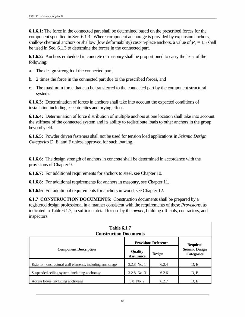
1997 Provisions, Chapter 6
88
6.1.6.1: The force in the connected part shall be determined based on the prescribed forces for thecomponent specified in Sec. 6.1.3. Where component anchorage is provided by expansion anchors,shallow chemical anchors or shallow (low deformability) cast-in-place anchors, a value of R = 1.5 shallp
be used in Sec. 6.1.3 to determine the forces in the connected part.
6.1.6.2: Anchors embedded in concrete or masonry shall be proportioned to carry the least of thefollowing:
a. The design strength of the connected part,
b. 2 times the force in the connected part due to the prescribed forces, and
c. The maximum force that can be transferred to the connected part by the component structuralsystem.
6.1.6.3: Determination of forces in anchors shall take into account the expected conditions ofinstallation including eccentricities and prying effects.
6.1.6.4: Determination of force distribution of multiple anchors at one location shall take into accountthe stiffness of the connected system and its ability to redistribute loads to other anchors in the groupbeyond yield.
6.1.6.5: Powder driven fasteners shall not be used for tension load applications in Seismic DesignCategories D, E, and F unless approved for such loading.
6.1.6.6: The design strength of anchors in concrete shall be determined in accordance with theprovisions of Chapter 9.
6.1.6.7: For additional requirements for anchors to steel, see Chapter 10.
6.1.6.8: For additional requirements for anchors in masonry, see Chapter 11.
6.1.6.9: For additional requirements for anchors in wood, see Chapter 12.
6.1.7 CONSTRUCTION DOCUMENTS: Construction documents shall be prepared by aregistered design professional in a manner consistent with the requirements of these Provisions, asindicated in Table 6.1.7, in sufficient detail for use by the owner, building officials, contractors, andinspectors.
Table 6.1.7Construction Documents
Component Description Seismic Design
Provisions Reference Required
CategoriesQuality
AssuranceDesign
Exterior nonstructural wall elements, including anchorage 3.2.8 No. 1 6.2.4 D, E
Suspended ceiling system, including anchorage 3.2.8 No. 3 6.2.6 D, E
Access floors, including anchorage 3.8 No. 2 6.2.7 D, E

Architectural, Mechanical, and Electrical Components Design Requirements
Table 6.1.7Construction Documents
Component Description Seismic Design
Provisions Reference Required
CategoriesQuality
AssuranceDesign
89
Steel storage racks, including anchorage 3.2.8 No. 2 6.2.9 D, E
HVAC ductwork containing hazardous materials, includinganchorage
3.2.9 No. 4 6.3.10 C, D, E
Piping systems and mechanical units containing flammable,combustible, or highly toxic materials
3.2.9 No. 3 6.3.12 C, D, E6.3.11
6.3.13
Anchorage of electrical equipment for emergency or standbypower systems
3.2.9 No. 1 6.3.14 C, D, E
Anchorage of all other electrical equipment 3.2.9 No. 2 6.3.14 E
Project-specific requirements for mechanical and electricalcomponents and their anchorage
3.3.5 6.30 C, D, E
6.2 ARCHITECTURAL COMPONENT DESIGN:
6.2.1 GENERAL: Architectural systems, components, or elements (hereinafter referred to as"components") listed in Table 6.2.2 and their attachments shall meet the requirements of Sec. 6.2.2through Sec. 6.2.9.
6.2.2 ARCHITECTURAL COMPONENT FORCES AND DISPLACEMENTS: Architecturalcomponents shall meet the force requirements of Sec. 6.1.3 and 6.4 and Table 6.2.2.
Exception: Components supported by chains or otherwise suspended from the structuralsystem above are not required to meet the lateral seismic force requirements and seismicrelative displacement requirements of this section provided that they cannot be damaged orcannot damage any other component when subject to seismic motion and they have ductile orarticulating connections to the structure at the point of attachment. The gravity design load forthese items shall be three times their operating load.
TABLE 6.2.2Architectural Components Coefficients
Architectural Component or Element a Rpa
pb
Interior Nonstructural Walls and Partitions (See also Sec. 6.8)Plain (unreinforced) masonry wallsAll other walls and partitions
1.0 1.251.0 2.5

1997 Provisions, Chapter 6
Architectural Component or Element a Rpa
pb
90
Cantilever Elements (Unbraced or braced to structural frame below its center of mass)Parapets and cantilever interior nonstructural wallsChimneys and stacks where laterally supported by structures
2.5 2.52.5 2.5
Cantilever Elements (Braced to structural frame above its center of mass)Parapets 1.0 2.5Chimneys and Stacks 1.0 2.5Exterior Nonstructural Walls 1.0 2.5 c
Exterior Nonstructural Wall Elements and Connections (see also Sec. 6.2.4)Wall ElementBody of wall panel connections Fasteners of the connecting system
1.0 2.51.0 2.51.25 1
VeneerHigh deformability elements and attachmentsLow deformability elements and attachments
1.0 2.51.0 1.25
Penthouses (except when framed by an extension of the building frame) 2.5 3.5
Ceilings (see also Sec. 6.2.6)All 1.0 2.5
CabinetsStorage cabinets and laboratory equipment 1.0 2.5
Access floors (see also Sec. 6.2.7)Special access floors (designed in accordance with Sec. 6.2.7.2) 1 2.5All other 1 1.25
Appendages and Ornamentations 2.5 2.5
Signs and Billboards 2.5 2.5
Other Rigid ComponentsHigh deformability elements and attachments 1.0 3.5Limited deformability elements and attachments 1.0 2.5Low deformability elements and attachments 1.0 1.25
Other flexible componentsHigh deformability elements and attachmentsLimited deformability elements and attachmentsLow deformability elements and attachments
2.5 3.52.5 2.52.5 1.25
A lower value for a may be justified by detailed dynamic analysis. The value for a shall not be less than 1.00. Theap p
value of a = 1 is for equipment generally regarded as rigid and rigidly attached. The value of a = 2.5 is for flexiblep p
components or flexibly attached components. See Chapter 2 for definitions of rigid and flexible components includingattachments.

Architectural, Mechanical, and Electrical Components Design Requirements
91
R = 1.25 for anchorage design when component anchorage is provided by expansion anchor bolts, shallow chemicalbp
anchors, or shallow (nonductile) cast-in-place anchors or when the component is constructed of nonductile materials. Powder-actuated fasteners (shot pins) shall not be used for component anchorage in tension applications in Seismic DesignCategories D, E, or F. Shallow anchors are those with an embedment length-to-diameter ratio of less than 8.
Where flexible diaphragms provide lateral support for walls and partitions, the design forces for anchorage to the c
diaphragm shall be as specified in Sec. 5.2.5.4.4 .
6.2.3 ARCHITECTURAL COMPONENT DEFORMATION: Architectural components thatcould pose a life-safety hazard shall be designed for the seismic relative displacement requirements ofSec. 6.1.4. Architectural components shall be designed for vertical deflection due to joint rotation ofcantilever structural members.
6.2.4 EXTERIOR NONSTRUCTURAL WALL ELEMENTS AND CONNECTIONS: Exterior nonstructural wall panels or elements that are attached to or enclose the structure shall bedesigned to resist the forces in accordance with Eq. 6.1.3-1 or 6.1.3-2, and shall accommodatemovements of the structure resulting from response to the design basis ground motion, D orp
temperature changes. Such elements shall be supported by means of positive and direct structuralsupports or by mechanical connections and fasteners in accordance with the following requirements:
a. Connections and panel joints shall allow for a relative movement between stories of not less thecalculated story drift D , or 1/2 inch (13 mm), whichever is greatest.p
b. Connections to permit movement in the plane of the panel for story drift shall be slidingconnections using slotted or oversize holes, connections that permit movement by bending of steel,or other connections that provide equivalent sliding or ductile capacity.
c. Bodies of connectors shall have sufficient deformability and rotation capacity to preclude fractureof the concrete or low deformation failures at or near welds.
d. All fasteners in the connecting system such as bolts, inserts, welds, and dowels and the body of theconnectors shall be designed for the force (F ) determined in by Eq. 6.1.3-2 with values of R andp p
a taken from Table 6.2.2 applied at the center of mass of the panel.p
e. Anchorage using flat straps embedded in concrete or masonry shall be attached to or hookedaround reinforcing steel or otherwise terminated so as to effectively transfer forces to thereinforcing steel.
6.2.5 OUT-OF-PLANE BENDING: Transverse or out-of-plane bending or deformation of acomponent or system that is subjected to forces as determined in Sec. 6.1.3 shall not exceed thedeflection capability of the component or system.
6.2.6 SUSPENDED CEILINGS: Suspended ceilings shall be designed to meet the seismic forcerequirements of Sec. 6.2.6.1. In addition, suspended ceilings shall meet the requirements of eitherIndustry Standard Construction as modified in Sec. 6.2.6.2 or Integral Construction as specified in Sec.6.2.6.3.
6.2.6.1 Seismic Forces: Suspended ceilings shall be designed to meet the force requirements ofSec. 6.1.3.

1997 Provisions, Chapter 6
92
The weight of the ceiling, W , shall include the ceiling grid and panels; light fixtures if attached to,p
clipped to, or laterally supported by the ceiling grid; and other components which are laterallysupported by the ceiling. W shall be taken as not less than 4 pounds per square foot (19 N/m )p
2
The seismic force, F , shall be transmitted through the ceiling attachments to the building structuralp
elements or the ceiling-structure boundary.
Design of anchorage and connections shall be in accordance with these provisions.
6.2.6.2 Industry Standard Construction: Unless designed in accordance with Sec. 6.2.6.3,suspended ceilings shall be designed and constructed in accordance with this section.
6.2.6.2.1 Seismic Design Category C: Suspended ceilings in Seismic Design Category C shall bedesigned and installed in accordance with the Ceilings and Interior Systems Construction Association(CISCA) recommendations for seismic zones 0-2 (Ref. 6-14), except that seismic forces shall bedetermined in accordance with Sec. 6.1.3 and 6.2.6.1.
Sprinkler heads and other penetrations in Seismic Design Category C shall have a minimum of 1/4 inch(6 mm) clearance on all sides.
6.2.6.2.2 Seismic Design Categories D, E, and F: Suspended ceilings in Seismic Design CategoriesD, E, and F shall be designed and installed in accordance with the Ceilings and Interior SystemsConstruction Association (CISCA) recommendations for seismic zones 3-4 (Ref. 6-15) and theadditional requirements listed in this subsection.
a. A heavy duty T-bar grid system shall be used.
b. The width of the perimeter supporting closure angle shall be not less than 2.0 inches (50 mm). Ineach orthogonal horizontal direction, one end of the ceiling grid shall be attached to the closureangle. The other end in each horizontal direction shall have a 3/4 inch (19 mm) clearance from thewall and shall rest upon and be free to slide on a closure angle.
c. For ceiling areas exceeding 1000 square feet (92.9 m ), horizontal restraint of the ceiling to the2
structural system shall be provided. The tributary areas of the horizontal restraints shall beapproximately equal.
Exception: Rigid braces are permitted to be used instead of diagonal splay wires. Braces and attachments to the structural system above shall be adequate to limitrelative lateral deflections at point of attachment of ceiling grid to less than 1/4 inch (6mm) for the loads prescribed in Sec. 6.1.3
d. For ceiling areas exceeding 2500 square feet (232 m ), a seismic separation joint or full height2
partition that breaks the ceiling up into areas not exceeding 2500 square feet shall be providedunless structural analyses are performed of the ceiling bracing system for the prescribed seismicforces which demonstrate ceiling system penetrations and closure angles provide sufficientclearance to accommodate the additional movement. Each area shall be provided with closureangles in accordance with Item b and horizontal restraints or bracing in accordance with Item c.
e. Except where rigid braces are used to limit lateral deflections, sprinkler heads and otherpenetrations shall have a 2 inch (50 mm) oversize ring, sleeve, or adapter through the ceiling tile to

Architectural, Mechanical, and Electrical Components Design Requirements
93
allow for free movement of at least 1 inch (25 mm) in all horizontal directions. Alternatively, aswing joint that can accommodate 1 inch (25 mm) of ceiling movement in all horizontal directionsare permitted to be provided at the top of the sprinkler head extension.
f. Changes in ceiling plan elevation shall be provided with positive bracing.
g. Cable trays and electrical conduits shall be supported independently of the ceiling.
h. Suspended ceilings shall be subject to the special inspection requirements of Sec. 3.3.9 of theseProvisions.
6.2.6.3 Integral Ceiling/Sprinkler Construction: As an alternate to providing large clearancesaround sprinkler system penetrations through ceiling systems, the sprinkler system and ceiling grid arepermitted to be designed and tied together as an integral unit. Such a design shall consider the massand flexibility of all elements involved, including: ceiling system, sprinkler system, light fixtures, andmechanical (HVAC) appurtenances. The design shall be performed by a registered designprofessional.
6.2.7 ACCESS FLOORS:
6.2.7.1 General: Access floors shall be designed to meet the force provisions of Sec. 6.1.3 and theadditional provisions of this section. The weight of the access floor, W , shall include the weight of thep
floor system, 100 percent of the weight of all equipment fastened to the floor, and 25 percent of theweight of all equipment supported by, but not fastened to the floor. The seismic force, F , shall bep
transmitted from the top surface of the access floor to the supporting structure.
Overturning effects of equipment fastened to the access floor panels also shall be considered. Theability of "slip on" heads for pedestals shall be evaluated for suitability to transfer overturning effects ofequipment.
When checking individual pedestals for overturning effects, the maximum concurrent axial load shallnot exceed the portion of W assigned to the pedestal under consideration.p
6.2.7.2 Special Access Floors: Access floors shall be considered to be "special access floors" if theyare designed to comply with the following considerations:
1. Connections transmitting seismic loads consist of mechanical fasteners, concrete anchors, welding,or bearing. Design load capacities comply with recognized design codes and/or certified testresults.
2. Seismic loads are not transmitted by friction produced solely by the effects of gravity, powder-actuated fasteners (shot pins), or adhesives.
3. The bracing system shall be designed considering the destabilizing effects of individual membersbuckling in compression.
4. Bracing and pedestals are of structural or mechanical shape produced to ASTM specifications thatspecify minimum mechanical properties. Electrical tubing shall not be used.
5. Floor stringers that are designed to carry axial seismic loads and that are mechanically fastened tothe supporting pedestals are used.

1997 Provisions, Chapter 6
94
6.2.8 PARTITIONS: Partitions that are tied to the ceiling and all partitions greater than 6 ft (1.8 m)in height shall be laterally braced to the building structure. Such bracing shall be independent of anyceiling splay bracing. Bracing shall be spaced to limit horizontal deflection at the partition head to becompatible with ceiling deflection requirements as determined in Sec. 6.2.6 for suspended ceilings andSec. 6.2.2 for other systems.
6.2.9 STEEL STORAGE RACKS: Steel storage racks shall be designed to meet the forcerequirements of Chapter 14:
6.3 MECHANICAL AND ELECTRICAL COMPONENT DESIGN:
6.3.1 GENERAL: Attachments and equipment supports for the mechanical and electrical systems,components, or elements (hereinafter referred to as "components") shall meet the requirements of Sec.6.3.2 through Sec. 6.3.16.
6.3.2 MECHANICAL AND ELECTRICAL COMPONENT FORCES ANDDISPLACEMENTS: Mechanical and electrical components shall meet the force and seismic relativedisplacement requirements of Sec. 6.1.3, Sec. 6.1.4, and Table 6.3.2.
Some complex equipment such as valves and valve operators, turbines and generators, and pumps andmotors are permitted to be functionally connected by mechanical links not capable of transferring theseismic loads or accommodating seismic relative displacements and may require special designconsiderations such as a common rigid support or skid.
Exception: Components supported by chains or similarly suspended structure above are notrequired to meet the lateral seismic force requirements and seismic relative displacementrequirements of this section provided that they cannot be damaged or cannot damage anyother component when subject to seismic motion and they have high deformation orarticulating connections to the building at the point of attachment. The gravity design load forthese items shall be three times their operating load.
TABLE 6.3.2Mechanical and Electrical Components Coefficients
Mechanical and Electrical Component or Element a Rcpa
pb
General Mechanical Boilers and furnaces 1.0 2.5Pressure vessels on skirts and free-standing 2.5 2.5Stacks 2.5 2.5Cantilevered chimneys 2.5 2.5Other 1.0 2.5
Manufacturing and Process MachineryGeneral 1.0 2.5 Conveyors (nonpersonnel) 2.5 2.5
Piping Systems High deformability elements and attachments 1.0 3.5Limited deformability elements and attachments 1.0 2.5Low deformability elements or attachments 1.0 1.25

Tp ' 2BWp
Kp g
Architectural, Mechanical, and Electrical Components Design Requirements
Mechanical and Electrical Component or Element a Rcpa
pb
95
(6.3.3)
HVAC System EquipmentVibration isolated 2.5 2.5Nonvibration isolated 1.0 2.5Mounted in-line with ductwork 1.0 2.5Other 1.0 2.5
Elevator Components 1.0 2.5
Escalator Components 1.0 2.5
Trussed Towers (free-standing or guyed) 2.5 2.5
General Electrical Distributed systems (bus ducts, conduit, cable tray) 2.5 5 Equipment 1.0 2.5
Lighting Fixtures 1.0 1.25
A lower value for a is permitted provided a detailed dynamic analysis is performance which justifies a lower limit. ap
The value for a shall not be less than 1.00. The value of a = 1 is for equipment generally regarded as rigid or rigidly attached. p p
The value of a = 2.5 is for flexible components or flexibly attached components. See Chapter 2 for definitions of rigid andp
flexible components including attachments. R = 1.25 for anchorage design when component anchorage is provided by expansion anchor bolts, shallow chemicalb
p
anchors, or shallow low deformability cast-in-place anchors or when the component is constructed of nonductile materials. Powder-actuated fasteners (shot pins) shall not be used for component anchorage in Seismic Design Categories D, E, or F. Shallow anchors are those with an embedment length-to- diameter ratio of less than 8.
Components mounted on vibration isolation systems shall have a bumper restraint or snubber in each horizontalc
direction. The design force shall be taken as 2F .p
6.3.3 MECHANICAL AND ELECTRICAL COMPONENT PERIOD: The fundamental periodof the mechanical and electrical component (and its attachment to the building), T , may be determinedp
by the following equation provided that the component and attachment can be reasonably representedanalytically by a simple spring and mass single-degree-of-freedom system:
where:
T = Component fundamental period,p
W = Component operating weight,p
g = Gravitational acceleration, and
K = Stiffness of resilient support system of the component and attachment, determined in terms ofp
load per unit deflection at the center of gravity of the component.
Note that consistent units must be used.
Alternatively, determine the fundamental period of the component in seconds (T ) from experimentalp
test data or by a properly substantiated analysis.

1997 Provisions, Chapter 6
96
6.3.4 MECHANICAL AND ELECTRICAL COMPONENT ATTACHMENTS: The stiffnessof mechanical and electrical component attachments shall be designed such that the load path for thecomponent performs its intended function.
6.3.5 COMPONENT SUPPORTS: Mechanical and electrical component supports and the meansby which they are attached to the component shall be designed for the forces determined in Sec. 6.1.3and in conformance with Chapters 5 through 9, as appropriate, for the materials comprising the meansof attachment. Such supports include structural members, braces, frames, skirts, legs, saddles,pedestals, cables, guys, stays, snubbers, and tethers. Component supports may be forged or cast as apart of the mechanical or electrical component. If standard or proprietary supports are used, they shallbe designed by either load rating (i.e., testing) or for the calculated seismic forces. In addition, thestiffness of the support, when appropriate, shall be designed such that the seismic load path for thecomponent performs its intended function.
Component supports shall be designed to accommodate the seismic relative displacements betweenpoints of support determined in accordance with Sec. 6.1.4.
In addition, the means by which supports are attached to the component, except when integral (i.e.,cast or forged), shall be designed to accommodate both the forces and displacements determined inaccordance with Sec. 6.1.3 and 6.1.4. If the value of I = 1.5 for the component, the local region of thep
support attachment point to the component shall be evaluated for the effect of the load transfer on thecomponent wall.
6.3.6 COMPONENT CERTIFICATION: The manufacturer's certificate of compliance with theforce requirements of the Provisions shall be submitted to the regulatory agency when required by thecontract documents or when required by the regulatory agency.
6.3.7 UTILITY AND SERVICE LINES AT STRUCTURE INTERFACES: At the interface ofadjacent structures or portions of the same structure that may move independently, utility lines shall beprovided with adequate flexibility to accommodate the anticipated differential movement between theground and the structure. Differential displacement calculations shall be determined in accordance withSec. 6.1.4.
6.3.8 SITE-SPECIFIC CONSIDERATIONS: The possible interruption of utility service shall beconsidered in relation to designated seismic systems in Seismic Use Group III as defined in Sec. 1.3.1. Specific attention shall be given to the vulnerability of underground utilities and utility interfacesbetween the structure and the ground in all situations where Site Class E or F soil is present and wherethe seismic coefficient C is equal to or greater than 0.15.a
6.3.9 STORAGE TANKS:
6.3.9.1 Above-Grade Storage Tanks: For storage tanks mounted above grade in structures,attachments, supports, and the stank shall be designed to meet the force requirements of Chapter 14.
6.3.10 HVAC DUCTWORK: Attachments and supports for HVAC ductwork systems shall bedesigned to meet the force and displacement requirements of Sec. 6.1.3 and 6.1.4 and the additional requirements of this section. In addition to their attachments and supports, ductwork systemsdesignated as having an I greater than 1.0 shall be designed to meet the force and displacement p
requirements of Sec. 6.1.3 and 6.1.4 and the additional requirements of this section. Where HVACductwork runs between structures that could displace relative to one another and for isolated

Architectural, Mechanical, and Electrical Components Design Requirements
97
structures where the HVAC ductwork crosses the isolation interface, the HVAC ductwork shall bedesigned to accommodate the seismic relative displacements specified in Sec. 6.1.4.
Seismic restraints are not required for HVAC ducts with I = 1.0 if either of the following conditionsp
are met for the full length of each duct run:
a. HVAC ducts are suspended from hangers, and all hangers are 12 in. (305 mm) or less in lengthfrom the top of the duct to the supporting structure and the hangers are detailed to avoidsignificant bending of the hangers and their attachments.
or
b. HVAC ducts have a cross-sectional area of less than 6 ft (0.557 m ).2 2
HVAC duct systems fabricated and installed in accordance with the SMACNA duct constructionstandards (Ref. 6-16, 6-17, and 6-18) shall be deemed to meet the lateral bracing requirements of thissection.
Equipment items installed in-line with the duct system (e.g., fans, heat exchangers, and humidifiers) with an operating weight greater than 75 lb (334 N) shall be supported and laterally braced independently of the duct system and shall meet the force requirements of Sec. 6.1.3. Appurtenancessuch as dampers, louvers, and diffusers shall be positively attached with mechanical fasteners. Unbraced piping attached to in-line equipment shall be provided with adequate flexibility toaccommodate differential displacements.
6.3.11 PIPING SYSTEMS: Attachments and supports for piping systems shall be designed to meetthe force and displacement requirements of Sec. 6.1.3 and 6.1.4 and the additional requirements ofthis section. In addition to their attachments and supports, piping systems designated as having I p
greater than 1.0 themselves shall be designed to meet the force and displacement provisions of Sec.6.1.3 and 6.1.4 and the additional requirements of this section. When piping systems are attached tostructures that could displace relative to one another and for isolated structures, including foundations,where the piping system crosses the isolation interface, the piping system shall be designed toaccommodate the seismic relative displacements specified in Sec. 6.1.4.
Seismic effects that shall be considered in the design of a piping system include the dynamic effects ofthe piping system, its contents, and, when appropriate, its supports. The interaction between the pipingsystem and the supporting structures, including other mechanical and electrical equipment, shall also beconsidered.
See Sec. 6.3.16 for elevator system piping requirements.
6.3.11.1 Fire Protection Sprinkler Systems: Fire protection sprinkler systems designed andconstructed in accordance with Ref. 6-12 shall be deemed to meet the force, displacement, and otherrequirements of this section provided that the seismic design force and displacement calculated inaccordance with Ref. 6-12, multiplied by a factor of 1.4, is not less than that determined using theseProvisions.
6.3.11.2 Other Piping Systems. The following documents have been adopted as national standardsby the American National Standards Institute (ANSI), and are appropriate for use in the seismic design

1997 Provisions, Chapter 6
98
of piping systems provided that the seismic design forces and displacements used are comparable tothose determined using these Provisions.
Exception: Piping systems designated as having an I greater than 1.0 shall not be designedp
using the simplified analysis procedures of Ref. 6-9 (Sec. 919.4.1(a)).
The following requirements shall also be met for piping systems designated as having an I greater thanp
1.0
a. Under design loads and displacements, piping shall not be permitted to impact other components.
b. Piping shall accommodate the effects of relative displacements that may occur between pipingsupport points on the structure or the ground, other mechanical and/or electrical equipment, and other piping.
6.3.11.2.1 Supports and Attachments for Other Piping: In addition to meeting the force,displacement, and other requirements of this section, attachments and supports for piping shall besubject to the following other requirements and limitations:
a. Attachments shall be designed in accordance with Sec. 6.1.6 .
b. Seismic supports are not required for:
1. Piping supported by rod hangers provided that all hangers in the pipe run are 12 in. (305 mm)or less in length from the top of the pipe to the supporting structure and the pipe canaccommodate the expected deflections. Rod hangers shall not be constructed in a manner thatwould subject the rod to bending moments.
2. High deformability piping in Seismic Design Categories D, E, and F designated as having an Ip
greater than 1.0 and a nominal pipe size of 1 in. (25 mm) or less when provisions are made toprotect the piping from impact or to avoid the impact of larger piping or other mechanicalequipment.
3. High deformability piping in Seismic Design Category C designated as having an I greaterp
than 1.0 and a nominal pipe size of 2 in. (51 mm) or less when provisions are made to protectthe piping from impact or to avoid the impact of larger piping or other mechanical equipment.
4. High deformability piping in Seismic Design Categories D, E, and F designated as having an Ip
equal to 1.0 and a nominal pipe size of 3 in. (76 mm) or less.
c. Seismic supports shall be constructed so that support engagement is maintained.
6.3.12 BOILERS AND PRESSURE VESSELS: Attachments and supports for boilers and pressurevessels shall be designed to meet the force and displacement provisions of Sec. 6.1.3 and 6.1.4 and theadditional provisions of this section. In addition to their attachments and supports, boilers and pressurevessels designated as having an I = 1.5 themselves shall be designed to meet the force andp
displacement provisions of Sec. 6.1.3 and 6.1.4.
Seismic effects that shall be considered in the design of a boiler or pressure vessel include the dynamiceffects of the boiler or pressure vessel, its contents, and its supports; sloshing of liquid contents; loads

Architectural, Mechanical, and Electrical Components Design Requirements
99
from attached components such as piping; and the interaction between the boiler or pressure vessel andits support.
6.3.12.1 ASME Boilers and Pressure Vessels: Boilers or pressure vessels designed in accordancewith Ref. 6-9 shall be deemed to meet the force, displacement, and other requirements of this section. In lieu of the specific force and displacement provisions provided in the ASME code, the force anddisplacement provisions of Sec. 6.1.3 and 6.1.4 shall be used.
6.3.12.2 Other Boilers and Pressure Vessels: Boilers and pressure vessels designated as having an Ip
= 1.5 but not constructed in accordance with the provisions of Ref. 6-9 shall meet the followingprovisions:
a. The design strength for seismic loads in combination with other service loads and appropriateenvironmental effects shall not exceed the following:
(1) For boilers and pressure vessels constructed with ductile materials (e.g., steel, aluminum orcopper), 90 percent of the material minimum specified yield strength.
(2) For threaded connections in boilers or pressure vessels or their supports constructed withductile materials, 70 percent of the material minimum specified yield strength.
(3) For boilers and pressure vessels constructed with nonductile materials (e.g., plastic, cast iron,or ceramics), 25 percent of the material minimum specified tensile strength.
(4) For threaded connections in boilers or pressure vessels or their supports constructed withnonductile materials, 20 percent of the material minimum specified tensile strength.
b. Provisions shall be made to mitigate seismic impact for boiler and pressure vessel componentsconstructed of nonductile materials or in cases where material ductility is reduced (e.g., lowtemperature applications).
c. Boilers and pressure vessels shall be investigated to ensure that the interaction effects betweenthem and other constructions are acceptable.
6.3.12.3 Supports and Attachments for Boilers and Pressure Vessels: Attachments and supportsfor boilers and pressure vessels shall meet the following provisions:
a. Attachments and supports transferring seismic loads shall be constructed of materials suitable forthe application and designed and constructed in accordance with nationally recognized structuralcode such as, when constructed of steel, Ref. 8-1 and 8-2.
b. Attachments embedded in concrete shall be suitable for cyclic loads.
c. Seismic supports shall be constructed so that support engagement is maintained.
6.3.13 MECHANICAL EQUIPMENT ATTACHMENTS AND SUPPORTS: Attachments andsupports for mechanical equipment not covered in Sec. 6.3.8 through 6.3.12 or 6.3.16 shall bedesigned to meet the force and displacement requirements of Sec. 6.1.3 and 6.1.4 and the additional requirements of this section. In addition, mechanical equipment designated as having an I greaterp
than 1.0 shall be designed to meet the force and displacement requirements of Sec. 6.1.3 and 6.1.4and the additional requirements of this section.

1997 Provisions, Chapter 6
100
When required, seismic effects that shall be considered in the design of mechanical equipment,attachments and their supports include the dynamic effects of the equipment, its contents, and whenappropriate its supports. The interaction between the equipment and the supporting structures,including other mechanical and electrical equipment, shall also be considered.
6.3.13.1 Mechanical Equipment: Mechanical equipment having an I greater than 1.0 shall meet thep
following requirements.
a . Provisions shall be made to eliminate seismic impact for equipment components vulnerable toimpact, equipment components constructed of nonductile materials, or in cases where materialductility is reduced (e.g., low temperature applications).
b . The possibility for loadings imposed on the equipment by attached utility or service lines due todifferential motions of points of support from separate structures shall be evaluated.
In addition, components of mechanical equipment designated as having an I greater than 1.0 andp
containing sufficient material that would be hazardous if released shall themselves be designed forseismic loads. The design strength for seismic loads in combination with other service loads andappropriate environmental effects such as corrosion shall be based on the following:
a. For mechanical equipment constructed with ductile materials (e.g., steel, aluminum, or copper), 90percent of the equipment material minimum specified yield strength.
b. For threaded connections in equipment constructed with ductile materials, 70 percent of thematerial minimum specified yield strength.
c. For mechanical equipment constructed with nonductile materials (e.g., plastic, cast iron, orceramics), 25 percent of the equipment material minimum tensile strength.
d. For threaded connections in equipment constructed with nonductile materials, 20 percent of thematerial minimum specified yield strength.
6.3.13.2 Attachments and Supports for Mechanical Equipment: Attachments and supports formechanical equipment shall meet the following requirements :
a. Attachments and supports transferring seismic loads shall be constructed of materials suitable forthe application and designed and constructed in accordance with a nationally recognized structuralstandard specification such as, when constructed of steel, Ref. 8-1 and 8-2.
b. Friction clips shall not be used for anchorage attachment.
c. Expansion anchors shall not be used for nonvibration isolated mechanical equipment rated over 10hp (7.45 kW ).
Exception: Undercut expansion anchors are permitted.
d. Supports shall be specifically evaluated if weak-axis bending of cold-formed support steel is reliedon for the seismic load path.
e. Components mounted on vibration isolation systems shall have a bumper restraint or snubber ineach horizontal direction, and vertical restraints shall be provided where required to resistoverturning. Isolator housings and restraints shall be constructed of ductile materials. (See
Architectural, Mechanical, and Electrical Components Design Requirements
101
additional design force requirements in Table 6.3.2.) A viscoelastic pad or similar material ofappropriate thickness shall be used between the bumper and equipment item to limit the impactload.
f. Seismic supports shall be constructed so that support engagement is maintained.
6.3.14 ELECTRICAL EQUIPMENT ATTACHMENTS AND SUPPORTS: Attachments andsupports for electrical equipment shall be designed to meet the force and displacement requirements ofSec. 6.1.3 and 6.1.4 and the additional requirements of this section. In addition, electrical equipmentdesignated as having I greater than 1.0 shall itself be designed to meet the force and displacement p
requirements of Sec. 6.1.3 and 6.1.4 and the additional requirements of this section.
Seismic effects that shall be considered in the design of other electrical equipment include the dynamiceffects of the equipment, its contents, and when appropriate its supports. The interaction between theequipment and the supporting structures, including other mechanical and electrical equipment, shallalso be considered. When conduit, cable trays, or similar electrical distribution components areattached to structures that could displace relative to one another and for isolated structures where theconduit or cable trays cross the isolation interface, the conduit or cable trays shall be designed toaccommodate the seismic relative displacements specified in Sec. 6.1.4.
6.3.14.1 Electrical Equipment: Electrical equipment designated as having an I greater than 1.0 p
shall meet the following requirements:
a. Provisions shall be made to eliminate seismic impact between the equipment and other components.
b. Evaluate loading on the equipment imposed by attached utility or service lines which are alsoattached to separate structures.
c. Batteries on racks shall have wrap-around restraints to ensure that the batteries will not fall off therack. Spacers shall be used between restraints and cells to prevent damage to cases. Racks shall beevaluated for sufficient lateral load capacity.
d. Internal coils of dry type transformers shall be positively attached to their supporting substructurewithin the transformer enclosure.
e. Slide out components in electrical control panels, computer equipment, etc., shall have a latchingmechanism to hold contents in place.
f. Electrical cabinet design shall conform to the applicable National Electrical ManufacturersAssociation (NEMA) standards. Cut-outs in the lower shear panel that do not appear to have beenmade by the manufacturer and are judged to significantly reduce the strength of the cabinet shall bespecifically evaluated.
g. The attachment of additional external items weighing more than 100 pounds (445 N) shall bespecifically evaluated if not provided by the manufacturer.
6.3.14.2 Attachments and Supports for Electrical Equipment: Attachments and supports forelectrical equipment shall meet the following requirements:

1997 Provisions, Chapter 6
102
a. Attachments and supports transferring seismic loads shall be constructed of materials suitable forthe application and designed and constructed in accordance with a nationally recognized structuralstandard specification such as, when constructed of steel, Ref. 5-1 and 5-2.
b. Friction clips shall not be used for anchorage attachment.
c. Oversized plate washers extending to the equipment wall shall be used at bolted connectionsthrough the base sheet metal if the base is not reinforced with stiffeners or not judged capable oftransferring the required loads.
d. Supports shall be specifically evaluated if weak-axis bending of light gage support steel is relied onfor the seismic load path.
e. The supports for linear electrical equipment such as cable trays, conduit, and bus ducts shall bedesigned to meet the force and displacement requirements of Sec. 6.1.3 and 6.1.4 if any of thefollowing situations apply:
(1) Supports are cantilevered up from the floor;
(2) Supports include bracing to limit deflection;
(3) Supports are constructed as rigid welded frames;
(4) Attachments into concrete utilize nonexpanding insets, shot pins, or cast iron embedments;
(5) Attachments utilize spot welds, plug welds, or minimum size welds as defined by AISC.
f. Components mounted on vibration isolation systems shall have a bumper restraint or snubber ineach horizontal direction, and vertical restraints shall be provided where required to resistoverturning. Isolator housings and restraints shall not be constructed of cast iron or other materialswith limited ductility. (See additional design force requirements in Table 6.3.2.) A viscoelastic pador similar material of appropriate thickness shall be used between the bumper and equipment itemto limit the impact load.
6.3.15 ALTERNATIVE SEISMIC QUALIFICATION METHODS: As an alternative to theanalysis methods implicit in the design methodology described above, equipment testing is anacceptable method to determine seismic capacity. Thus, adaptation of a nationally recognizedstandard, such as Ref. 6-16, is acceptable so long as the equipment seismic capacity equals or exceedsthe demand expressed in Sec. 6.1.3 and 6.1.4.
6.3.16 ELEVATOR DESIGN REQUIREMENTS: Elevators shall meet the force anddisplacement provisions of Sec. 6.3.2 unless exempted by either Sec. 1.2 or Sec. 6.1. Elevatorsdesigned in accordance with the seismic provisions of Ref. 6-1 shall be deemed to meet the seismicforce requirements of this section, except they also shall meet the additional requirements provided inSec. 6.3.16.1 through 6.3.16.4..
6.3.16.1 Elevators and Hoistway Structural System: Elevators and hoistway structural systemsshall be designed to meet the force and displacement provisions of Sec. 6.3.2.

6.3.16.2 Elevator Machinery and Controller Supports and Attachments: Elevator machinery andcontroller supports and attachments shall be designed to meet the force and displacement provisions ofSec. 6.3.2.
6.3.16.3 Seismic Controls: Seismic switches shall be provided for all elevators addressed by Sec.6.3.16.1 including those meeting the requirements of the ASME reference, provided they operate witha speed of 150 ft/min (46 m/min) or greater. Seismic switches shall provide an electrical signalindicating that structural motions are of such a magnitude that the operation of elevators may beimpaired. Upon activation of the seismic switch, elevator operations shall conform to provisions inRef. 6-1 except as noted below. The seismic switch shall be located at or above the highest floorserviced by the elevators. The seismic switch shall have two horizontal perpendicular axes ofsensitivity. Its trigger level shall be set to 30 percent of the acceleration of gravity
In facilities where the loss of the use of an elevator is a life-safety issue, the elevator may be used afterthe seismic switch has triggered provided that:
1. The elevator shall operate no faster than the service speed,
2. The elevator shall be operated remotely from top to bottom and back to top to verify that it isoperable, and
3. The individual putting the elevator back in service should ride the elevator from top to bottom andback to top to verify acceptable performance.
6.3.16.4 Retainer Plates: Retainer plates are required at the top and bottom of the car and coun-terweight.

105
Chapter 7
FOUNDATION DESIGN REQUIREMENTS
7.1 GENERAL: This chapter includes only those foundation requirements that are specificallyrelated to seismic resistant construction. It assumes compliance with all other basic requirements. These requirements include, but are not limited to, requirements for the extent of the foundationinvestigation, fills to be present or to be placed in the area of the structure, slope stability, subsurfacedrainage, and settlement control. Also included are pile requirements and capacities and bearing andlateral soil pressure recommendations.
7.2 STRENGTH OF COMPONENTS AND FOUNDATIONS: The resisting capacities of thefoundations, subjected to the prescribed seismic forces of Chapters 1, 4 and 5, shall meet the require-ments of this chapter.
7.2.1 Structural Materials: The strength of foundation components subjected to seismic forcesalone or in combination with other prescribed loads and their detailing requirements shall conform tothe requirements of Chapter 8, 9, 10, 11, or 12. The strength of foundation components shall not beless than that required for forces acting without seismic forces.
7.2.2 Soil Capacities: The capacity of the foundation soil in bearing or the capacity of the soilinterface between pile, pier, or caisson and the soil shall be sufficient to support the structure with allprescribed loads, without seismic forces, taking due account of the settlement that the structure canwithstand. For the load combination including earthquake as specified in Sec. 5.2.7, the soil capacitiesmust be sufficient to resist loads at acceptable strains considering both the short duration of loading andthe dynamic properties of the soil.
7.3 SEISMIC DESIGN CATEGORIES A AND B: Any construction meeting the requirements ofSec. 7.1 and 7.2 is permitted to be be used for structures assigned to Seismic Design Category A or B.
7.4 SEISMIC DESIGN CATEGORY C: Foundations for structures assigned to Seismic DesignCategory C shall conform to all of the requirements for Seismic Design Categories A and B and to theadditional requirements of this section.
7.4.1 Investigation: The authority having jurisdiction may require the submission of a written reportthat shall include, in addition to the requirements of Sec. 7.1 and the evaluations required in Sec. 7.2.2,the results of an investigation to determine the potential hazards due to slope instability, liquefaction,and surface rupture due to faulting or lateral spreading, all as a result of earthquake motions.
7.4.2 Pole-Type Structures: Construction employing posts or poles as columns embedded in earthor embedded in concrete footings in the earth are permitted to be used to resist both axial and lateralloads. The depth of embedment required for posts or poles to resist seismic forces shall be determinedby means of the design criteria established in the foundation investigation report.

1997 Provisions, Chapter 7
106
7.4.3 Foundation Ties: Individual pile caps, drilled piers, or caissons shall be interconnected by ties. All ties shall be capable of carrying, in tension or compression, a force equal to the product of thelarger pile cap or column load times S divided by 4 unless it can be demonstrated that equivalentDS
restraint can be provided by reinforced concrete beams within slabs on grade or reinforced concreteslabs on grade or confinement by competent rock, hard cohesive soils, very dense granular soils, orother approved means.
7.4.4 Special Pile Requirements: The following special requirements for concrete piles, concretefilled steel pipe piles, drilled piers, or caissons are in addition to all other requirements in the codeadministered by the authority having jurisdiction.
All concrete piles and concrete filled pipe piles shall be connected to the pile cap by embedding the pilereinforcement in the pile cap for a distance equal to the development length as specified in Ref. 6-1. The pile cap connection can be made by the use of field-placed dowels anchored in the concrete pile. For deformed bars, the development length is the full development length for compression withoutreduction in length for excess area. Where special reinforcement at the top of the pile is required,alternative measures for laterally confining concrete and maintaining toughness and ductile-likebehavior at the top of the pile will be permitted provided due consideration is given to forcing the hingeto occur in the confined region.
Where a minimum length for reinforcement or the extent of closely spaced confinement reinforcementis specified at the top of the pile, provisions shall be made so that those specified lengths or extents aremaintained after pile cut-off.
7.4.4.1 Uncased Concrete Piles: A minimum reinforcement ratio of 0.0025 shall be provided foruncased cast-in-place concrete drilled piles, drilled piers, or caissons in the top one-third of the pilelength or a minimum length of 10 ft (3 m) below the ground. There shall be a minimum of four barswith closed ties (or equivalent spirals) of a minimum 1/4 in. (6 mm) diameter provided at 16-longitudinal-bar-diameter maximum spacing with a maximum spacing of 4 in. (102 mm) in the top 2 ft(0.6 m) of the pile. Reinforcement detailing requirements shall be in conformance with Sec. 9.6.2.
7.4.4.2 Metal-Cased Concrete Piles: Reinforcement requirements are the same as for uncasedconcrete piles.
Exception: Spiral welded metal-casing of a thickness not less than No. 14 gauge can beconsidered as providing concrete confinement equivalent to the closed ties or equivalent spiralsrequired in an uncased concrete pile, provided that the metal casing is adequately protectedagainst possible deleterious action due to soil constituents, changing water levels, or otherfactors indicated by boring records of site conditions.
7.4.4.3 Concrete-Filled Pipe: Minimum reinforcement 0.01 times the cross-sectional area of the pileconcrete shall be provided in the top of the pile with a length equal to two times the required capembedment anchorage into the pile cap.
7.4.4.4 Precast Concrete Piles: Longitudinal reinforcement shall be provided for precast concretepiles with a minimum steel ratio of 0.01. Ties or equivalent spirals shall be provided at a maximum 16-bar-diameter spacing with a maximum spacing of 4 in. (102 mm) in the top 2 ft (0.6 m). Rein-forcement shall be full length.

Foundation Design Requirements
107
7.4.4.5 Precast-Prestressed Piles: The upper 2 ft (0.6 m) of the pile shall have No. 3 ties minimum atnot over 4-in. (102 mm) spacing or equivalent spirals. The pile cap connection is permitted to be bymeans of dowels as required in Sec. 7.4.4. Pile cap connection is permitted to be by means ofdeveloping pile reinforcing strand if a ductile connection is provided.
7.5 SEISMIC DESIGN CATEGORIES D, E, AND F: Foundations for structures assigned to Seismic Design Categories D, E, and F shall conform to all of the requirements for Seismic DesignCategory C construction and to the additional requirements of this section.
7.5.1 Investigation: The owner shall submit to the authority having jurisdiction a written report thatincludes an evaluation of potential site hazards such as slope instability, liquefaction, and surfacerupture due to faulting or lateral spreading and the determination of lateral pressures on basement andretaining walls due to earthquake motions.
7.5.2 Foundation Ties: Individual spread footings founded on soil defined in Sec. 4.1.2 as Site ClassE or F shall be interconnected by ties. Ties shall conform to Sec. 7.4.3.
7.5.3 Liquefaction Potential and Soil Strength Loss: The geotechnical report shall assess potentialconsequences of any liquefaction and soil strength loss, including estimation of differential settlement,lateral movement or reduction in foundation soil-bearing capacity, and shall discuss mitigationmeasures. Such measures shall be given consideration in the design of the structure and can include,but are not limited to, ground stabilization, selection of appropriate foundation type and depths,selection of appropriate structural systems to accommodate anticipated displacements, or anycombination of these measures.
The potential for liquefaction and soil strength loss shall be evaluated for site peak groundaccelerations, magnitudes, and source characteristics consistent with the design earthquake groundmotions. Peak ground acceleration is permitted to be determined based on a site-specific study takinginto account soil amplification effects or, in the absence of such a study, peak ground accelerationsshall be assumed equal to S /2.5.DS
7.5.4 Special Pile Requirements: Piling shall be designed and constructed to withstand maximumimposed curvatures from earthquake ground motions and structure response. Curvatures shall includefree-field soil strains (without the structure) modified for soil-pile-structure interaction coupled withpile deformations induced by lateral pile resistance to structure seismic forces. Concrete piles in SiteClass E or F shall be designed and detailed in accordance with Sec. 9.3.3.3 within seven pile diametersof the pile cap and the interfaces of soft to medium stiff clay or liquefiable strata.
7.5.4.1 Uncased Concrete Piles: A minimum reinforcement ratio of 0.005 shall be provided foruncased cast-in-place concrete piles, drilled piers, or caissons in the top one-half of the pile length or aminimum length of 10 ft (3 m) below ground. There shall be a minimum of four bars with closed tiesor equivalent spirals provided at 8-longitudinal-bar-diameter maximum spacing with a maximumspacing of 3 in. (76 mm) in the top 4 ft (1.2 m) of the pile. Ties shall be a minimum of No. 3 bars forup to 20-in.-diameter (500 mm) piles and No. 4 bars for piles of larger diameter.

1997 Provisions, Chapter 7
108
7.5.4.2 Metal-Cased Concrete Piles: Reinforcement requirements are the same as for uncasedconcrete piles.
Exception: Spiral welded metal-casing of a thickness not less than No. 14 gauge can beconsidered as providing concrete confinement equivalent to the closed ties or equivalent spiralsrequired in an uncased concrete pile, provided that the metal casing is adequately protectedagainst possible deleterious action due to soil constituents, changing water levels, or otherfactors indicated by boring records of site conditions.
7.5.4.3 Precast Concrete Piles: Ties in precast concrete piles shall conform to the requirements ofChapter 9 for at least the top half of the pile.
7.5.4.4 Precast-Prestressed Piles: For the body of fully embedded foundation piling subjected tovertical loads only, or where the design bending moment does not exceed 0.20M (where M is thenb nb
unfactored ultimate moment capacity at balanced strain conditions as defined in Ref. 6-1, Sec. 10.3.2),spiral reinforcing shall be provided such that D $ 0.006. Pile cap connection shall not be made bys
developing exposed strand.
7.5.4.5 Steel Piles: The connection between the pile cap and steel piles or unfilled steel pipe piles shallbe designed for a tensile force equal to 10 percent of the pile compression capacity.

109
Chapter 8
STEEL STRUCTURE DESIGN REQUIREMENTS
8.1 REFERENCE DOCUMENTS: The design, construction, and quality of steel components thatresist seismic forces shall conform to the requirements of the references listed in this section except asmodified by the requirements of this chapter.
Ref. 8-1 Load and Resistance Factor Design Specification for Structural Steel Buildings(LRFD), American Institute of Steel Construction (AISC), December 1993
Ref. 8-2 Allowable Stress Design and Plastic Design Specification for Structural SteelBuildings (ASD), American Institute of Steel Construction, June 1, 1989
Ref. 8-3 Seismic Provisions for Structural Steel Buildings, American Institute of SteelConstruction, 1997, Part I
Ref. 8-4 Specification for the Design of Cold-Formed Steel Structural Members, AmericanIron and Steel Institute (AISI), 1996
Ref. 8-5 Specification for the Design of Cold-formed Stainless Steel Structural Members,ANSI/ASCE 8-90, American Society of Civil Engineers
Ref. 8-6 Standard Specification, Load Tables and Weight Tables for Steel Joists and JoistGirders, Steel Joist Institute, 1994 Edition
Ref. 8-7 Structural Applications for Steel Cables for Buildings, ASCE 19, 1995 Edition
8.2 SEISMIC REQUIREMENTS FOR STEEL STRUCTURES: The design of steel structuresto resist seismic forces shall be in accordance with Section 8.3 or 8.4 for the appropriate SeismicDesign Category.
8.3 SEISMIC DESIGN CATEGORIES A, B and C: Steel structures assigned to Seismic DesignCategories A, B and C, shall be of any construction permitted by the references in Sec. 8.1. An Rfactor as set forth in Table 5.2.2 for the appropriate steel system is permitted when the structure isdesigned and detailed in accordance with the requirements of Ref. 8-3, Part I, or Sec. 8.6, for lightframed cold-formed steel wall systems. Systems not detailed in accordance with the above shall usethe R factor in Table 5.2.2 designated for “steel systems not detailed for seismic”.
8.4 SEISMIC DESIGN CATEGORIES D, E, and F: Steel structures assigned to Seismic DesignCategories D, E, and F shall be designed and detailed in accordance with Ref. 8-3, Part I, or Sec. 8.6for light framed cold-formed steel wall systems.
8.5 COLD-FORMED STEEL SEISMIC REQUIREMENTS: The design of cold-formed carbonor low-alloy steel members to resist seismic loads shall be in accordance with the requirements of Ref.8.-4 and the design of cold-formed stainless steel structural l to resist seismic loads shall be in

1997 Provisions, Chapter 8
110
accordance with the requirements of Ref. 8-5, except as modified by this section. The reference tosection and paragraph numbers are to those of the particular specification modified.
8.5.1 Modifications to Ref. 8-4: Revise Sec. A5.1.3 of Ref. 8-4 as follows:
"A4.4 Wind or Earthquake Loads Where load combinations specified by theapplicable code include wind loads, the resulting forces are permitted to be multiplied by0.75. Seismic load combinations shall be as determined by these provisions."
8.5.2 Modifications to Ref. 8-5: Modify Sec. 1.5.2 of Ref. 8-5 by substituting a load factor of 1.0 inplace of 1.5 for nominal earthquake load.
8.6 LIGHT-FRAMED WALLS: When required by the requirements in Sec. 8.3 or 8.4, cold-formed steel stud walls designed in accordance with Ref. 8-4 and 8-5 shall also comply with therequirements of this section.
8.6.1 Boundary Members: All boundary members, chords, and collectors shall be designed totransmit the specified induced axial forces .
8.6.2 Connections: Connections for diagonal bracing members, top chord splices, boundarymembers, and collectors shall have a design strength equal to or greater than the nominal tensilestrength of the members being connected or S times the design seismic force. The pull-out resistance0
of screws shall not be used to resist seismic forces.
8.6.3 Braced Bay Members: In stud systems where the lateral forces are resisted by braced frames,the vertical and diagonal members in braced bays shall be anchored such that the bottom tracks are notrequired to resist uplift forces by bending of the track or track web. Both flanges of studs shall bebraced to prevent lateral torsional buckling. In vertical diaphragm systems, the vertical boundarymembers shall be anchored so the bottom track is not required to resist uplift forces by bending of thetrack web.
8.6.4 Diagonal Braces: Provision shall be made for pretensioning or other methods of installation oftension-only bracing to guard against loose diagonal straps.
8.6.5 Shear Walls: Nominal shear values for wall sheathing materials are given in Table 8.6. Designshear values shall be determined by multiplying the nominal values therein by a N factor of 0.55. Instructures over one story in height, the assemblies in Table 8.6 shall not be used to resist horizontalloads contributed by forces imposed by masonry or concrete construction.
Panel thicknesses shown in Table 8.6 shall be considered to be minimums. No panels less than 24inches wide shall be used. Plywood or oriented strand board structural panels shall be of a type that ismanufactured using exterior glue. Framing members, blocking or strapping shall be provided at theedges of all sheets. Fasteners along the edges in shear panels shall be placed not less than 3/8 inches(9.5 mm) in from panel edges. Screws shall be of sufficient length to assure penetration into the steelstud by at least two full diameter threads.
The height to length ratio of wall systems listed in Table 8.6 shall not exceed 2:1.
Perimeter members at openings shall be provided and shall be detailed to distribute the shearingstresses. Wood sheathing shall not be used to splice these members.

Steel Structure Design Requirements
111
Wall studs and track shall have a minimum uncoated base thickness of not less than 0.033 inches (0.84mm) and shall not have an uncoated base metal thickness greater than 0.048 inches (1.22 mm). Panelend studs and their uplift anchorage shall have the design strength to resist the forces determined by theseismic loads determined by Eq. 2.2.6-3 and Eq. 2.2.6-4.
TABLE 8.6 Nominal Shear Values for Seismic Forces for Shear WallsFramed with Cold-Formed Steel Studs (in pounds per foot)a, b
Assembly Fastener Spacing at Panel FramingDescription Edges Spacingc
(inches) (inches o.c.)
6 4 3 2
15/32 rated Structural I sheathing 780 990 1465 1625 24(4-ply) plywood one side d
7/16 in. oriented strand board one 700 915 1275 1700 24side d
NOTE: For fastener and framing spacing, multiply inches by 25.4 to obtain metric mm.
Nominal shear values shall be multiplied by the appropriate strength reduction factor N to determinea
design strength as set forth in Sec. 8.6.5.
Studs shall be a minimum 1-5/8 in. by 3-1/2 in. with a 3/8-in. return lip. Track shall be a minimum 1-b
1/4 in. by 3-1/2 in. Both studs and track shall have a minimum uncoated base metal thickness of 0.033inches and shall be ASTM A446 Grade A (or ASTM A653 SQ Grade 33 [new designation]). Framingscrews shall be No. 8 x 5/8 in. wafer head self-drilling. Plywood and OSB screws shall be a minimum No. 8x 1 in. bugle head. Where horizontal straps are used to provide blocking they shall be a minimum 1-1/2 in.wide and of the same material and thickness as the stud and track.
Screws in the field of the panel shall be installed 12 inches o.c. unless otherwise shown.c
Both flanges of the studs shall be braced in accordance with Sec. 8.6.3.d
8.7 SEISMIC REQUIREMENTS FOR STEEL DECK DIAPHRAGMS: Steel deckdiaphragms shall be made from materials conforming to the requirements of Ref. 8-4 or 8-5. Nominalstrengths shall be determined in accordance with approved analytical procedures or with testprocedures prepared by a registered design professional experienced in testing of cold-formed steelassemblies and approved by the authority having jurisdiction. Design strengths shall be determined bymultiplying the nominal strength by a resistance factor, N, equal to 0.60 (for mechanically connecteddiaphragms) and equal to 0.50 (for welded diaphragms). The steel deck installation for the structure,including fasteners, shall comply with the test assembly arrangement. Quality standards established forthe nominal strength test shall be the minimum standards required for the steel deck installation,including fasteners.
8.8 STEEL CABLES: The design strength of steel cables shall be determined by the requirements ofRef. 8-7 except as modified by these Provisions. Sec. 5d of Ref. 8-7 shall be modified by substituting1.5(T ) where T is the net tension in cable due to dead load, prestress, live load, and seismic load. A4 4
load factor of 1.1 shall be applied to the prestress force to be added to the load combination of Sec.3.1.2 of Ref. 8-7.

c )
u P )
u M )
n
P )
u
113
Chapter 9
CONCRETE STRUCTURE DESIGN REQUIREMENTS
9.1 REFERENCE DOCUMENTS: The quality and testing of concrete and steel materials and thedesign and construction of concrete components that resist seismic forces shall conform to therequirements of the reference listed in this section except as modified by the requirements of thischapter.
Ref. 9-1 Building Code Requirements for Structural Concrete, American Concrete Institute,ACI 318-95, excluding Appendix A
9.1.1 Modifications to Ref. 9-1:
9.1.1.1: Replace Sec. 9.2.3 with Sec. 5.2.7 of these Provisions. Add the following:
“9.3.1.2 For load combinations that include earthquake loads, the design strength shall becomputed using the strength reduction factors, N, listed in Appendix C.”
9.1.1.2: Insert the following notations in Sec. 21.0:
" = the angle between the diagonal reinforcement and the longitudinalaxis.
A = the area, in. (mm ) of the shank of the bolt or stud.b2 2
A = total area of reinforcement in each group of diagonal bars.vd
= neutral axis depth at and .
R = height of the plastic hinge above critical section and which shall bep
established on the basis of substantiated test data or may be alternatelytaken at 0.5R .w
= 1.2D + 0.5L + E.
h = Overall dimension of member in the direction of action considered.
S = moment, shear, or axial force at connection cross section other thane Connection
the nonlinear action location corresponding to probable strength at thenonlinear action location, taking gravity load effects into considerationper 21.2.7.3.
S = nominal strength of connection cross section in flexural, shear, or axialn Connection
action per 21.2.7.3.
) = elastic design displacement at the top of the wall using gross sectionE
properties and code-specified seismic forces.

(M )
n/ME))E
M )
n
P )
u
1997 Provisions, Chapter 9
114
) = inelastic deflection at top of wall = ) - ) .i t y
) = C )m d s.
) = design level response displacement, which is the total drift or totals
story drift that occurs when the structure is subjected to the designseismic forces.
) = total deflection at the top of the wall equal to C times the elastic designt d
displacement using cracked section properties or may be taken as(I /I )C ) . I is the gross moment of inertia of the wall and I is theg eff d E g eff
effective moment of inertia of the wall. I may be taken as 0.5I .eff g
) = displacement at the top of the wall corresponding to yielding of the tensiony
reinforcement at critical section or may be taken as where ME
equals moment at critical section when top of wall is displaced ) . isE
nominal flexural strength of critical section at .
N = yield curvature which may be estimated as 0.003/R .y w
Q = dynamic amplification factor from 21.2.7.3 and 21.2.7.4.
9.1.1.3: Insert the following definitions in Sec. 21.1:
"Connection -- An element that joins two precast members or a precast member and a cast-in-place member.
“Dry Connection -- Connection used between precast members which does not qualify as awet connection.
"Joint -- The geometric volume common to intersecting members.
"Nonlinear Action Location -- Center of the region of yielding in flexure, shear, or axialaction.
“Nonlinear Action Region -- The member length over which nonlinear action takes place. It shall be taken as extending a distance of no less than h/2 on either side of the nonlinearaction location.
“Strong Connection -- A connection that remains elastic while the designated nonlinearaction regions undergo inelastic response under the design basis ground motion.
“Wet Connection -- A connection that uses any of the splicing methods, per 21.2.6.1 or21.3.2.3, to connect precast members and uses cast-in-place concrete or grout to fill thesplicing closure.”
9.1.1. 4: Replace Sec. 21.2.1.3 and 21.2.1.4 with the requirements of Sec. 9.4 through 9.7.

Concrete Structure Design Requirements
115
9.1.1.5: Insert the following new Sec. 21.2.1.6 and 21.2.1.7:
"21.2.1.6 A precast seismic-force-resisting system shall be permitted provided it satisfieseither of the following criteria:
"1. It emulates the behavior of monolithic reinforced concrete construction and satisfies21.2.2.5, or
"2. It relies on the unique properties of a structural system composed of interconnectedprecast elements and it is demonstrated by experimental evidence and analysis tosafely sustain the seismic loading requirements of a comparable monolithic reinforcedconcrete structure satisfying Chapter 21. Substantiating experimental evidence ofacceptable performance of those elements required to sustain inelastic deformationsshall be based upon cyclic inelastic testing of specimens representing those elements.
“21.2.1.7 In structures having precast gravity load carrying systems, the seismic-force-resisting system shall be one of the systems listed in Table 5.2.2 of the 1997 NEHRPRecommended Provisions and shall be well distributed using one of the following methods:
“1. The seismic-force-resisting system shall be spaced such that the span of the diaphragmor diaphragm segment between seismic-force-resisting systems shall be no more thanthree times the width of the diaphragm or diaphragm segment. Where the seismic-force-resisting system consists of moment resisting frames, at least (N /4) + 1 of theb
bays (rounded up to the nearest integer) along any frame line at any story shall be partof the seismic-force-resisting system where N is the total number of bays along thatb
line at that story. This requirement applies to only the lower two thirds of the storiesof buildings three stories or taller.
“2. All beam-to-column connections that are not part of the seismic-force-resisting systemshall be designed in accordance with the following:
Connection Design Force. The connection shall be designed to developstrength M. M is the moment developed at the connection when the frame isdisplaced by ) assuming fixity at the connection and a beam flexural stiffness ofs
no less than one half of the gross section stiffness. M shall be sustained througha deformation of ) .m
Connection Characteristics. The connection shall be permitted to resistmoment in one direction only, positive or negative. The connection at theopposite end of the member shall resist moment with the same positive ornegative sign. The connection shall be permitted to have zero flexural stiffnessup to a frame displacement of ) .m
In addition, complete calculations for the deformation compatibility of the gravityload carrying system shall be made in accordance with 5.2.2.4.3 of the 1997NEHRP Recommended Provisions using cracked section stiffness in the seismic-force-resisting system and the diaphragm.
Where gravity columns are not provided with lateral support on all sides, apositive connection shall be provided along each unsupported direction parallel to

1997 Provisions, Chapter 9
116
a principal plan axis of the structure. The connection shall be designed for ahorizontal force equal to 4 percent of the axial load strength, P , of the column.o
The bearing length shall be calculated to include end rotation, sliding, and othermovements of precast ends at supports due to earthquake motions in addition toother movements and shall be at least 2 inches more than that required forbearing strength.”
9.1.1.6: Insert the following new Sec. 21.2.2.5, 21.2.2.6 and 21.2.2.7:
"21.2.2.5 Precast structural systems using frames and emulating the behavior of monolithicreinforced concrete construction shall satisfy either 21.2.2.6 or 21.2.2.7.
"21.2.2.6 Precast structural systems utilizing wet connections shall comply with all theapplicable requirements of monolithic concrete construction for resisting seismic forces.
"21.2.2.7 Precast structural systems not meeting 21.2.2.6 shall utilize strong connectionsresulting in nonlinear response away from connections. Design shall satisfy the requirementsof 21.2.7 in addition to all the applicable requirements of monolithic concrete constructionfor resisting seismic forces, except that provisions of 21.3.1.2 shall apply to the segmentsbetween nonlinear action locations.
9.1.1.7: Change Sec. 21.2.5.1 as follows and insert the following new Sec. 21.2.5.2 and 21.2.5.3.
“21.2.5.1 Except as permitted in 21.2.5.2 and 21.2.5.3, reinforcement resisting earthquake-induced flexural and axial forces in frame members and in wall boundary elements shallcomply with ASTM A 706. ASTM A 615 Grades 40 and 60 reinforcement shall bepermitted in these members if (a) the actual yield strength based on mill tests does notexceed the specified yield strength by more than 18,000 psi (retests shall not exceed thisvalue by more than an additional 3000 psi), and (b) the ratio of the actual ultimate tensilestrength to the actual tensile yield strength is not less than 1.25.
"21.2.5.2 Prestressing tendons shall be permitted in flexural members of frames providedthe average prestress, f , calculated for an area equal to the member's shortest cross-pc
sectional dimension multiplied by the perpendicular dimension shall not exceed the lesser of700 psi or f /6 at locations of nonlinear action where prestressing tendons are used inc
’
members of frames.
"21.2.5.3 For members in which prestressing tendons are used together with reinforcementto resist earthquake-induced forces, prestressing tendons shall not provide more than onequarter of the strength for both positive moments and negative moments at the joint faceand shall extend through exterior joints and be anchored at the exterior face of the joint orbeyond. Anchorages for tendons must be demonstrated to perform satisfactorily for seismicloadings. Anchorage assemblies shall withstand, without failure, a minimum of 50 cycles ofloading ranging between 40 and 85 percent of the minimum specified tensile strength of thetendon. Tendons shall extend through exterior joints and be anchored at the exterior face orbeyond."

NSnConnection > RSeConnection
Concrete Structure Design Requirements
117
(21-A)
9.1.1.8: Change Sec. 21.2.6.1 as follows:
“21.2.6.1 Reinforcement resisting earthquake-induced flexural or axial forces in framemembers or in wall boundary members is permitted to be spliced using welded splices ormechanical connectors conforming to 12.14.3.3 or 12.14.3.4 provided that: (a) not morethan alternate bars in each layer of longitudinal reinforcement are spliced at a section and (b)the center-to-center distance between splices of adjacent bars is 24 inches or more measuredalong the longitudinal axis of the member.
“Exception: Items (a) and (b) need not apply where splices are used outside the followinglocations (i) joints or (ii) where analysis indicates flexural yielding caused by inelastic lateraldisplacement of the frame.”
9.1.1.9: Insert the following new Sec. 21.2.7:
“21.2.7 Emulation of monolithic construction using strong connections. Membersresisting earthquake-induced forces in precast frames using strong connections shall satisfythe following:
“21.2.7.1 Location. Nonlinear action location shall be selected so that there is a strongcolumn/weak beam deformation mechanism under seismic effects. The nonlinear actionlocation shall be no closer to the near face of strong connection than h/2. For column-to-footing connections where nonlinear action may occur at the column base to complete themechanism, the nonlinear action location shall be no closer to the near face of theconnection than h/2.
“21.2.7.2 Anchorage and splices. Reinforcement in nonlinear action region shall be fullydeveloped outside both the strong connection region and the nonlinear action region. Noncontinuous anchorage reinforcement of strong connection shall be fully developedbetween the connection and the beginning of nonlinear action region. Lap splices areprohibited within connections adjacent to a joint.
“21.2.7.3 Design forces. Design strength of strong connections shall be based on:
Dynamic amplification factor, R, shall be taken as 1.0.
“21.2.7.4 Column-to-column connection. The strength of such connections shall complywith 21.2.7.3 with Q taken as 1.4. Where column-to-column connections occur, thecolumns shall be provided with transverse reinforcement as specified in 21.4.4.1 through21.4.4.3 over their full height if the factored axial compressive force in these members,including seismic effects, exceeds A f /10.g c
’
“Exception: Where column-to-column connection is located within the middle third of thecolumn clear height, the following shall apply: (a) the design moment strength, NM , of then
connection shall not be less than 0.4 times the maximum M for the column within the storypr
height and (b) the design shear strength NV of the connection shall not be less than thatn
determined per 21.4.5.1.

1997 Provisions, Chapter 9
118
“21.2.7.5 Column-face connection. Any strong connection located outside the middlehalf of a beam span shall be a wet connection unless a dry connection can be substantiatedby approved cyclic test results. Any mechanical connector located within such a column-face strong connection shall develop in tension or compression, as required, at least 40percent of the specified yield strength, f , of the bar.” y
9.1.1.10: Add the following new Sec. 21.4.5.3:
"21.4.5.3: At any section where the design strength, NP , of the column is less than then
sum of the shear V computed in accordance with 21.4.5.1 for all the beams framing into thee
column above the level under consideration, special transverse reinforcement shall beprovided. For beams framing into opposite sides of the column, the moment componentsmay be assumed to be of opposite sign. For determination of the nominal strength, P , ofn
the column, these moments may be assumed to result from the deformation of the frame inany one principal axis."
9.1.1.11: Change the reference to Sec. 9.2 in Sec. 21.6.3 to the load combination specified in Sec.5.2.7 of this document for earthquake forces.
9.1.1.12: Replace Sec. 21.6.4.1 with the following:
“21.6.4 Diaphragms used to resist prescribed lateral forces shall comply with thefollowing:
“1. Thickness shall not be less than 2 inches. Topping slabs placed over precast floor orroof elements shall not be less than 2-1/2 inches thick.
“2. Where mechanical connectors are used to transfer forces between the diaphragm andthe lateral system, the anchorage shall be adequate to develop 1.4A f where A is thes y s
connectors cross sectional area.
“3. Collector and boundary elements of topping slabs placed over precast floor and roofelements shall not be less than 3 inches or 6d thick where d is the diameter of theb b
largest reinforcing bar in the topping slab.
“4. Prestressing tendons shall not be used as primary reinforcement in boundaries andcollector elements of structural diaphragms. Precompression from unbonded tendonsmay be used to resist diaphragm forces.”
9.1.1.13 Replace Sec. 21.6.6 with the following:
“21.6.6 Design of structural walls for flexural and axial loads:
“21.6.6.1 Structural walls and portions of structural walls subject to combined flexural andaxial loads shall be designed in accordance with 10.2 and 10.3 except that 10.3.6 and thenonlinear strain requirements of 10.2.2 do not apply. The strength-reduction factor N shallbe in accordance with 9.3
“21.6.6.2 Unless a more detailed analysis is made, the design of flanges for I-, L-, C-, or T-shaped sections shall conform to the following:

Concrete Structure Design Requirements
119
“1. In compression, the effective flange width shall not be assumed to extend further fromthe face of the web than one-half the distance to an adjacent structural wall web or 15percent of the total height of the wall above the level considered.
“2. In tension, the amount of reinforcement used shall be not less than that within the webplus a distance on either side, extending from the face of the web, equal to the smallestof 30 percent of the total height of the wall above the level considered, one-half thedistance to an adjacent structural wall web, or the actual projection of the flange.
“21.6.6.3 Walls and portions of walls with P > 0.35P shall not be considered tou o
contribute to the calculated strength of the structure for resisting earthquake-inducedforces. Such walls shall conform to the requirements of 5.2.2.4.3 of the 1997 NEHRPRecommended Provisions.
“21.6.6.4 Structural walls and portions of structural walls shall have boundary zonessatisfying the requirements of 21.6.6.5, 21.6.6.6, or 21.6.6.7.
“21.6.6.5 No boundary zones shall be required if the following conditions exist:
“1. P # 0.10A f for geometrically symmetrical wall sectionsu g c’
P # 0.05A f for geometrically unsymmetrical wall sectionsu g c’
and either
“2. M /V R # 1.0u u w
or
“3. V # 3A %f and M /V R # 3.0u cv c u u w’
“21.6.6.6 Structural walls and portions of structural walls not satisfying 21.5.6.6.5 shall beprovided with boundary zones at each end dimensioned and reinforced in accordance with21.6.6.9. The horizontal lengths of those boundary zones shall be determined using 21.6.6.7or 21.6.6.8.
“21.6.6.7 Unless a more detailed analysis is made in accordance with 21.6.6.8, boundaryzone horizontal lengths shall be assumed to vary linearly from 0.25R to 0.15R for Pw w u
varying from 0.35P to 0.15P . The boundary zone horizontal length shall not be taken aso o
less than 0.15R .w
“21.6.6.8 Requirements for boundary zone horizontal lengths shall be determined based oncompressive strain levels at extreme edges when the wall or portion of wall is subjected todisplacement levels calculated from Eq. 5.3.7.1 of the 1997 NEHRP RecommendedProvisions using cracked shear area and moment of inertia properties and considering theresponse modifications effects of possible nonlinear behavior of the building.
Boundary zone detail requirements as defined in 21.6.6.9 shall be provided over those portions ofthe wall, horizontally and vertically, where compressive strains exceed 0.003. In no instance shalldesigns permit compressive strains greater than 0.015.

Nt ')i
hw &Rp
2Rp
% Ny
Ash '0.09 shc f )c
fyh
c )
u
c )
u
c )
u c )
u
1997 Provisions, Chapter 9
120
(21-B)
(21-C)
For structural walls in which flexural yielding at the base of the wall is the governing state,compressive strains at the extreme edges of walls may be determined as follows:
“1. The total curvature demand, N , shall be determined from Eq. (21-B)t
“2. If N is less than or equal to 0.003/ , boundary zone detailed as defined in 21.6.6.9 aret
not required. If N exceeds 0.003/ , the compressive strains may be assumed to varyt
linearly over the depth and have maximum value equal to the product of and N .t
“21.6.6.9 Structural wall boundary zone detail requirements. Boundary zone detailsshall meet the following:
“1. Dimensional requirements:
“1.1 All portions of the boundary zones shall have a thickness of R /16 or greater.u
“1.2 Boundary zones shall extend vertically a distance equal to the development length ofthe largest vertical bar within the boundary zone above the elevation where therequirements of 21.6.6.7 or 21.6.6.8 are met.
Extensions below the base of the boundary zone shall conform to 21.4.4.6.
Exception: The boundary zone reinforcement need not extend above theboundary zone a distance greater than the larger of R or M /4V .w u u
“1.3 Boundary zones as determined by the requirements of 21.6.6.8 shall have aminimum length of 18 inches at each end of the wall or portion of wall.
“1.4 In I-, L-, C-, or T-shaped sections, the boundary zone at each end shall includethe effective flange width in compression and shall extend at least 12 inches intothe web.
“2. Confinement reinforcement:
“2.1 All vertical reinforcement within the boundary zone shall be confined by hoops orcross ties producing an area of steel not less than:
“2.2 Hoops and cross ties shall have a vertical spacing not greater than the smaller of 6inches or 6 diameters of the smallest vertical bar within the boundary zone.
“2.3 The ratio of the length to the width of the hoops shall not exceed 3. All adjacenthoops shall be overlapped.

NVn ' 2N fy sin" Avd # 10N f )c bwd
0.83N f )cbwd
Concrete Structure Design Requirements
121
(21-D)
“2.4 Cross ties or legs of overlapping hoops shall not be spaced further apart than 12inches along the wall.
“2.5 Alternate vertical bars shall be confined by the corner of a hoop or cross tie.
“3. Horizontal reinforcement:
“3.1 All horizontal reinforcement terminating within a boundary zone shall beanchored in accordance with 21.6.2
“3.2 Horizontal reinforcement shall not be lap spliced within the boundary zone.
“4. Vertical reinforcement:
“4.1 Vertical reinforcement shall be provided to satisfy all tension and compressionrequirements.
“4.2 Area of reinforcement shall not be less than 0.005 times the area of boundaryzone or less than two No. 5 (#16) bars at each edge of boundary zone.
“4.3 Lap splices of vertical reinforcement within the boundary zone shall be confinedby hoops or cross ties. Spacing of hoops and cross ties confining lap-splicedreinforcement shall not exceed 4 inches.
9.1.1.14: Add a new Sec. 21.6.7 as follows and renumber existing Sec. 21.6.7 through 21.6.9 to21.6.8 through 21.6.10:
"21.6.7 Coupling Beams:
"21.6.7.1: For coupling beams with l /d $ 4, the design shall conform to the requirementsn
of 21.2 and 21.3. It shall be permitted to waive the requirements of 21.3.1.3 and 21.3.1.4 ifit can be shown by rational analysis that lateral stability is adequate or if alternative means ofmaintaining lateral stability is provided.
"21.6.7.2: Coupling beams with l /d < 4 shall be permitted to be reinforced with twon
intersecting groups of symmetrical diagonal bars. Coupling beams with l /d < 4 and withn
factored shear force V exceeding 4%f ’ b d metric equivalent is 0.332 %f ’ b d where f N isu c w c w c
in MPa and b and d are in mm)shall be reinforced with two intersecting groups ofw
symmetrical diagonal bars. Each group shall consist of a minimum of four bars assembled ina core each side of which is a minimum of b /2. The design shear strength, NV , of thesew n
coupling beams shall be determined by:
where N = 0.85.
The metric equivalent of the expression 10N%f b d, Eq. 21-D, is as follows:c w’
where b and d are in mm and f N is in MPa.w c

1997 Provisions, Chapter 9
122
Exception: The design of coupling beams need not comply with the requirements for diagonalreinforcement if it can be shown that failure of the coupling beams will not impair the verticalload carrying capacity of the structure, the egress from the structure, or the integrity ofnonstructural components and connections or produce other unacceptable effects. The analysisshall take into account the changes of stiffness of the structure due to the failure of couplingbeams. Design strength of coupling beams assumed to be part of the seismic-force-resistingsystem shall not be reduced below the values otherwise required.
"21.6.7.3: Each group of diagonally placed bars shall be enclosed in transversereinforcement conforming to 21.4.4.1 through 21.4.4.3. For the purpose of computing Ag
as per Eq. 10-6 and 21-3, the minimum cover as specified in 7.7 shall be assumed over eachgroup of diagonally placed reinforcing bars.
"21.6.7.4: Reinforcement parallel and transverse to the longitudinal axis shall be providedand, as a minimum, shall conform to 10.5, 11.8.9, and 11.8.10.
"21.6.7.5: Contribution of the diagonal reinforcement to nominal flexural strength of thecoupling beam area shall be considered.
9.1.1.5: Change Sec. 21.7.1 to read as follows:
“21.7.1: Frame members assumed not to contribute to lateral resistance shall be detailedaccording to 21.7.2 or 21.7.3 depending on the magnitude of moments induced in thosemembers when subjected to the lateral displacements of 5.2.2.4.3 of the 1997 NEHRPRecommended Provisions. Where effects of lateral displacements are not explicitlychecked, it shall be permitted to apply the requirements of 21.7.3.”
9.1.1.16: Change the title of Sec. 21.8 to read: "Requirements for Intermediate Moment Frames."
9.2 BOLTS AND HEADED STUD ANCHORS IN CONCRETE: Bolts and headed studanchors shall be solidly cast in concrete. The factored loads on embedded anchor bolts and headedstud anchors shall not exceed the design strengths determined by Sec. 9.2.2.
9.2.1 Load Factor Multipliers: In addition to the load factors in Sec. 5.2.7, a multiplier of 2 shall beused if special inspection is not provided or of 1.3 if it is provided. When anchors are embedded in thetension zone of a member, the load factors in Sec. 5.2.7 shall have a multiplier of 3 if special inspectionis not provided or of 2 if it is provided.
9.2.2 Strength of Anchors: Strength of anchors cast in concrete shall be taken as the lesser of thestrengths associated with concrete failure and anchor steel failure. Where feasible, anchorconnections, particularly those subject to seismic or other dynamic loads, shall be designed anddetailed such that connection failure is initiated by failure of the anchor steel rather than by failure ofthe surrounding concrete. Reinforcement also shall be permitted to be used for direct transfer oftension and shear loads. Such reinforcement shall be designed with proper consideration of itsdevelopment and its orientation with respect to the postulated concrete failure planes.
The strength of headed bolts and headed studs cast in concrete shall be based on testing in accordancewith Sec. 9.2.3 or calculated in accordance with Sec. 9.2.4. The bearing area of headed anchors shallbe at least one and one-half times the shank area.

Ps ' 0.9Ab Fu n
NPc ' N8 f )c(2.8As ) n
Concrete Structure Design Requirements
123
(9.2.4.1-1)
(9.2.4.1-2)
FIGURE 9.2.4.1a Shear cone failure for a singleheaded anchor.
9.2.3 Strength Based on Tests: The strength of anchors shall be based on not less than 10representative tests conforming to the proposed materials and anchor size and type, embedment length,and configuration as to attachment plates, loads applied, and concrete edge distances. The nominalstrength shall be the mean value derived from the tests minus one standard deviation. The strengthreduction factor applied to the nominal strength shall be 0.8 when anchor failure governs in themajority of the tests and 0.65 when concrete failure controls.
9.2.4 Strength Based on Calculations: Calculations for design strength shall be in accordance withSec. 9.2.4.1 through 9.2.4.3.
9.2.4.1 Strength in Tension: The design tensile strength of the individual anchors or adequatelyconnected groups of anchors shall be the minimum of P or NP where:s c
1. Design tensile strength governed by steel, P , in pounds (N), is:s
2. Design tensile strength governed by concrete failure, NP in pounds (N) is as follows:c
a. For individual anchors or groups of anchors with individual anchors spaced at least twicetheir embedment length apart and spaced not less than one anchor embedment length from afree edge of the concrete:
where:
A = area (in. ) of the assumed failure surface taken as a truncated cone slopings2
at 45 degrees from the head of the anchor to the concrete surface as shownin Figure 9.2.4.1a;
fN = concrete strength (psi)--6,000 psi (41 MPa) maximum;c

NPc 'N8 f )c(2.8As )n
12
NPc ' N8 f )c (2.8Ap % 4At)
1997 Provisions, Chapter 9
124
(9.2.4.1-3)
FIGURE 9.2.4.1b Truncated pyramid failure for agroup of headed anchors.
N = strength reduction factor of 0.65 except that where special transversereinforcing is provided to confine the concrete engaged by the anchor and isextended to pass through the failure surface into adjacent concrete, N ispermitted to be taken as 0.85;
8 = concrete weight factor--1 for normal weight concrete, 0.85 for sand-light-weight concrete, and 0.75 for lightweight concrete.
The metric equivalent of Eq. 9.2.4.1-2 is:
where A is in mm and fN is MPa.s c2
Where any anchors are closer to a free edge of the concrete than the anchor embedmentlength, the design tensile strength of those anchors shall be reduced proportionately to theedge distance divided by the embedment length. For multiple edge distances less than theembedment length, use multiple reductions.
b. For anchor groups where individual anchors are spaced closer together than twoembedment lengths:
where:
A = area (in. ) of an assumed failure surface taken as a truncated pyramidp2
extending from the heads of the outside anchors in the group at 45 degreesto the concrete surface as shown in Figure 9.2.4.1b;
A = area (in. ) of the flat bottom surface of the truncated pyramid of thet2
assumed concrete failure surface shown in Figure 9.2.4.1b.

NPc 'N8 f )c ( 2.8Ap % 4At )
12
Vs ' (0.75Ab Fu ) n
NVc ' (N800Ab8 f )c ) n
Concrete Structure Design Requirements
125
FIGURE 9.2.4.1c Pull-out failure surface for a groupof headed anchors in thin section.
(9.2.4.2-1)
(9.2.4.2-2)
The metric equivalent of Eq. 9.2.4.1-3 is:
where A and A are in mm and fN is in MPa.p t c2
If any anchors are closer to a free edge of the concrete than the anchor embedment length,the design tensile strength shall be reduced by using the reduced area A in the equationp
above.
Anchor groups shall be checked for a critical failure surface passing completely through aconcrete member along the 45 degree lines as shown in Figure 9.2.4.1c with A = 0 and At p
based on the area of the sloping failure surface passing completely through the concretemember. The lowest allowable load shall govern.
9.2.4.2 Strength in Shear: The design shear strength of anchors shall be the minimum of V or NVs c
where the design shear strength governed by steel failure is V , in pounds (N), and the design shears
strength governed by concrete failure is NV , in pounds (N). In situations where the embedment and/orc
concrete edge distances are limited, reinforcement to confine concrete to preclude its premature failureshall be permitted.
a. Where anchors are loaded toward an edge with edge distance d from the back row of anchors ase
shown in Figure 9.2.4.2 equal to or greater than 15 anchor diameters and the distance from thefront row of anchors to the edge equal to or greater than 6 anchor diameters:

NVc 'N800Ab8 f )c n
12
Vs ' (0.75Ab Fu ) nb
NVc ' NV )
c CwCtCc
1997 Provisions, Chapter 9
126
FIGURE 9.2.4.2 Shear on a group of headed an-chors.
(9.2.4.2-3)
(9.2.4.2-4)
where:
A = the area, in. (mm ) of the shank of the bolt or stud;b2 2
F = the specified ultimate tensile strength (psi) of the anchor. A307 bolts or A108 studsu
are permitted to be assumed to have F of 60,000 psi (414 MPa);u
n = the number of anchors;
8 = concrete weight factor--1 for normal weight concrete, 0.85 for sand-lightweightconcrete, and 0.75 for lightweight concrete; and
fN = concrete strength (psi)--6,000 psi (41 MPa) maximum.c
The metric equivalent of Eq. 9.2.4.2-2 is:
where A is in mm and fN is in MPa.b c2
b. Where anchors are loaded toward an edge with d less than 15 anchor diameters or the front rowe
closer to the edge than 6 anchor diameters:

NV )
c
NV )
c ' N12.5d 1.5e 8 f )c # 800Ab8 f )c
Cw ' 1 %b
3.5de
# nb
Ct 'h
1.3de
# 1.0
Cc ' 0.4 % 0.7dc
de
# 1.0
NV )
c 'N12.5d 1.5
e 8 f )c2.39
#N800Ab8 f )c
12
Concrete Structure Design Requirements
127
(9.2.4.2-5)
(9.2.4.2-6)
(9.2.4.2-7)
(9.2.4.2-8)
where:
A = the area (in. ) of the shank of the bolt or stud.b2
F = the specified ultimate tensile strength (psi) of the anchor. A307 bolts or A108 studsu
are permitted to be assumed to have F of 60,000 psi (414 MPa).u
n = the number of anchors in the back row.b
= the design shear strength of an anchor in the back row:
where d = the distance from the anchor axis to the free edge (in.).e
C = the adjustment factor for group width:w
where b = the center-to-center distance of outermost anchors in the back row (seeFigure 9.2.4.2) (in.) and d = the distance from the anchor axis to the free edge (in.).e
C = the adjustment factor for member thickness:t
where h = the thickness of concrete (in.) and d is as above.e
C = the adjustment factor for member corner effects:c
where d = the distance, measured perpendicular to the load, from the free edge of thec
concrete to the nearest anchor in in. (see Figure 9.2.4.2) and d is as above.e
The metric equivalent of Eq. 9.2.4.2-5 is:

1997 Provisions, Chapter 9
128
where d is in mm, A is in mm and fN is in MPa.e b c2

1N
Vu
Vc
# 1.0
1N
Pu
Pc
# 1.0
1N
Pu
Pc
2
%Vu
Vc
2
# 1.0
Pu
Ps
2
%Vu
Vs
2
# 1.0
Concrete Structure Design Requirements
129
(9.2.4.3-1a)
(9.2.4.3-1b)
(9.2.4.3-2a)
(9.2.4.3-2b)
9.2.4.3 Combined Tension and Shear: Where tension and shear act simultaneously, all of thefollowing conditions shall be met:
where:
P = required tensile strength, in pounds (N), based on factored loads andu
V = required shear strength, in pounds (N), based on factored loads.u
9.3 CLASSIFICATION OF SEISMIC-FORCE-RESISTING SYSTEMS: Reinforced concretemoment frames and structural concrete shear walls which resist seismic forces shall be classified inaccordance with Sec. 9.3.1 and Sec. 9.3.2, respectively.
9.3.1 Classification of Moment Frames: Reinforced concrete moment frames which resist seismicforces shall be classified in accordance with Sec. 9.3.1.1 through 9.3.1.3.
9.3.1.1 Ordinary Moment Frames: Ordinary moment frames are frames conforming to therequirements of Ref. 9-1 exclusive of Chapter 21.
9.3.1.1.1: Flexural members of ordinary moment frames forming part of the seismic-force-resistingsystem shall be designed in accordance with Sec. 7.13.2 of Ref. 9-1 and at least two main flexuralreinforcing bars shall be provided continuously top and bottom throughout the beams, through ordeveloped within exterior columns or boundary elements.
9.3.1.1.2: Columns of ordinary moment frames having a clear height to maximum plan dimensionratio of 5 or less shall be designed for shear in accordance with Sec. 21.8.3 of Ref. 9-1.

1997 Provisions, Chapter 9
130
9.3.1.2 Intermediate Moment Frames: Intermediate moment frames are frames conforming to therequirements of Sec. 21.1, 21.2.1.1, 12.2.1.2, 21.2.2.3, and 21.8 of Ref. 9-1 in addition to thoserequirements for ordinary moment frames.
9.3.1.3 Special Moment Frames: Special moment frames are frames conforming to therequirements of Sec. 21.1 through 21.5 of Ref. 9-1 in addition to those requirements for ordinarymoment frames.
9.3.2 Classification of Shear Walls: Structural concrete shear walls that resist seismic forces shallbe classified in accordance with Sec. 9.3.2.1 through 9.3.2.4.
9.3.2.1 Ordinary Plain Concrete Shear Walls: Ordinary plain concrete shear walls are wallsconforming to the requirements of Chapter 22 of Ref. 9-1.
9.3.2.2 Detailed Plain Concrete Shear Walls: Detailed plain concrete shear walls are walls abovethe base conforming to the requirements of Chapter 22 of Ref. 9-1 and containing reinforcement asfollows:
Vertical reinforcement of at least 0.20 in. (129 mm ) in cross-sectional area shall be provided2 2
continuously from support to support at each corner, at each side of each opening, at the ends of walls,and at a maximum spacing of 4 feet (1220 mm) apart horizontally throughout the walls.
Horizontal reinforcement at least 0.20 in. (129 mm ) in cross-sectional area shall be provided:2 2
a. Continuously at structurally connected roof and floor levels and at the top of walls,
b. At the bottom of load-bearing walls or in the top of foundations when doweled to the wall, and
c. At a maximum spacing of 120 inches (3050 mm).
Reinforcement at the top and bottom of openings, when used in determining the maximum spacingspecified in Item c above, shall be continuous in the wall.
Basement, foundation, or other walls below the base shall be reinforced as required by Sec. 22.6.6.5 ofRef. 9-1.
9.3.2.3 Ordinary Reinforced Concrete Shear Walls: Ordinary reinforced concrete shear walls arewalls conforming to the requirements of Ref. 9-1 exclusive of Chapters 21 and 22.
9.3.2.4 Special Reinforced Concrete Shear Walls: Special reinforced concrete shear walls arewalls conforming to the requirements of Sec. 21.1, 21.2, and 21.6 of Ref. 9-1 in addition to therequirements for ordinary reinforced concrete shear walls.
9.4 SEISMIC DESIGN CATEGORY A: Structures assigned to Seismic Design Category A maybe of any construction permitted in Ref. 9 -1 and these Provisions.
Exception: Ordinary moment frames in Seismic Design Category A are not required tocomply with Sec. 9.3.1.1.1 and 9.3.1.1.2.
9.5 SEISMIC DESIGN CATEGORY B: Structures assigned to Seismic Design Category B shallconform to all the requirements for Seismic Design Category A and to the additional requirements forSeismic Design Category B of this section and in other chapters of these Provisions.

Concrete Structure Design Requirements
131
9.5.1 Moment Frames: All moment frames that are part of the seismic-force-resisting system of abuilding assigned to Seismic Design Category B and founded on Site Class E or F soils shall beintermediate moment frames conforming to Sec. 9.3.1.2 or special moment frames conforming to Sec.9.3.1.3.
9.6 SEISMIC DESIGN CATEGORY C: Buildings assigned to Seismic Design Category C shallconform to all the requirements for Seismic Design Category B and to the additional requirements forSeismic Design Category C of this section and in other chapters of these Provisions.
9.6.1 Seismic-Force-Resisting Systems: Seismic-force-resisting systems shall conform to Sec.9.6.1.1 and Sec. 9.6.1.2.
9.6.1.1 Moment Frames: All moment frames that are part of the seismic-force-resisting system shallbe intermediate moment frames conforming to Sec. 9.3.1.2 or special moment frames conforming toSec. 9.3.1.3.
9.6.1.2 Shear Walls: All shear walls that are part of the seismic-force-resisting system shall bedetailed plain concrete shear walls conforming to Sec. 9.3.2.2, ordinary reinforced concrete shearwalls conforming to Sec. 9.3.2.3, or special reinforced concrete shear walls conforming to Sec.9.3.2.4.
9.6.2 Discontinuous Members: Columns supporting reactions from discontinuous stiff memberssuch as walls shall be designed for special load combinations in Sec. 5.2.7.1 and shall be provided withtransverse reinforcement at the spacing s as defined in Sec. 21.8.5.1 of Ref. 9-1 over their full heighto
beneath the level at which the discontinuity occurs. This transverse reinforcement shall be extendedabove and below the column as required in Sec. 21.4.4.5 of Ref. 9-1.
9.6.3 Plain Concrete: Structural plain concrete members in buildings assigned to Seismic DesignCategory C shall conform to Ref. 9-1 and the additional requirements and limitations of this section.
9.6.3.1 Walls: Walls used in the seismic-resisting-force system shall be detailed plain concrete shearwalls complying with Sec. 9.3.2.2. Other walls that are not serving as shear walls shall containreinforcement as required by Sec. 9.3.2.2.
9.6.3.2 Footings: Isolated footings of plain concrete supporting pedestals or columns are permittedprovided the projection of the footing beyond the face of the supported member does not exceed thefooting thickness.
Exception: In detached one- and two-family dwellings three stories or less in height, theprojection of the footing beyond the face of the supported member shall be permitted toexceed the footing thickness.
Plain concrete footings supporting walls shall be provided with not less than two continuouslongitudinal reinforcing bars. Bars shall not be smaller than No. 4 (#13) and shall have a total area ofnot less than 0.002 times the gross cross-sectional area of the footing. Continuity of reinforcementshall be provided at corners and intersections.
Exception: In detached one- and two-family dwellings three stories or less in height andconstructed with stud bearing walls, plain concrete footings supporting walls shall bepermitted without longitudinal reinforcement.

1997 Provisions, Chapter 9
132
9.6.3.3 Pedestals: Plain concrete pedestals shall not be used to resist lateral seismic forces.
9.7 SEISMIC DESIGN CATEGORIES D, E,OR F: Structures assigned to Seismic DesignCategory D, E or F shall conform to all of the requirements for Seismic Design Category C and to theadditional requirements of this section.
9.7.1 Seismic-Force-Resisting Systems: Seismic-force resisting systems shall conform to Sec.9.7.1.1 and Sec. 9.7.1.2.
9.7.1.1 Moment Frames: All moment frames that are part of the seismic-force-resisting system, re-gardless of height, shall be special moment frames conforming to Sec. 9.3.1.3.
9.7.1.2 Shear Walls: All shear walls that are part of the seismic-force-resisting system shall bespecial reinforced concrete shear walls conforming to Sec. 9.3.2.4.
9.7.2 Frame Members Not Proportioned to Resist Forces Induced by Earthquake Motions: Allframe components assumed not to contribute to lateral force resistance shall conform to Sec. 2.1.7 ofRef. 9-1 as modified by Sec. 9.1.1.15 of this chapter.
9.7.3 Plain Concrete: Structural plain concrete members are not permitted in buildings assigned toSeismic Design Category D, E or F.
Exceptions:
1. In detached one- and two-family dwellings three stories or less in height andconstructed with stud bearing walls, plain concrete footings without longitudinalreinforcement supporting walls and isolated plain concrete footings supportingcolumns or pedestals are permitted.
2. In all other buildings, plain concrete footings supporting walls are permitted providedthe footings are reinforced longitudinally as specified in Sec. 9.6.3.2.
3. In detached one- and two-family dwellings three stories or less in height andconstructed with stud bearing walls, plain concrete foundation or basement walls arepermitted provided the wall is not less than 7-1/2 in. (190 mm) thick and retains nomore than 4 ft (1219 mm) of unbalanced fill.

See the Commentary for this appendix for full reference information.**
133
Appendix to Chapter 9
REINFORCED CONCRETESTRUCTURAL SYSTEMS COMPOSED FROMINTERCONNECTED PRECAST ELEMENTS
PREFACE: The requirements for reinforced concrete structural systemscomposed of precast elements in the body of the Provisions are for precastsystems emulating monolithic reinforced concrete construction. However, one ofthe principal characteristics of precast systems is that they often are assembledusing dry joints where connections are made by bolting, welding, post-ten-sioning, or other similar means. Research conducted to date documentsconcepts for design using dry joints and the behavior of subassemblagescomposed from interconnected precast elements both at and beyond peakstrength levels for nonlinear reversed cyclic loadings (Applied TechnologyCouncil, 1981; Cheok and Lew, 1992; Clough, 1986; Eliott et al., 1987; Hawkinsand Englekirk, 1987; Jayashanker and French, 1988; Mast, 1992; Nakaki andEnglekirk, 1991; Neille, 1977; New Zealand Society, 1991; Pekau and Hum,1991; Powell et al., 1993; Priestley, 1991; Priestley and Tao, 1992; Stanton et al.,1986; Stanton et al., 1991). This appendix is included for information and as a**
compilation of the current understanding of the performance under seismicloads of structural systems composed from interconnected precast elements. It isconsidered premature to base code requirements on this resource appendix;however, user review, trial designs, and comment on this appendix are encour-aged. Please direct such feedback to the BSSC.
9A.1 GENERAL:
9A.1.1 Scope: Design and construction of seismic-force-resisting systems composed usinginterconnected precast concrete elements shall comply with the requirements of this appendix. Thequality and testing of concrete and steel materials and the design and construction of the precastconcrete components and systems that resist seismic forces shall conform to the requirements of thereference document listed in this section except as modified by the requirements of Chapter 9 and thisappendix.
9A.1.2 Reference Document:
Ref. 6A-1 Building Code Requirements for Reinforced Concrete, American Concrete Institute, ACI318- 95 excluding Appendices A and C.
9A.2 GENERAL PRINCIPLES: A reinforced concrete structural system composed frominterconnected precast concrete elements shall be permitted for the seismic-force-resisting system:

1997 Provisions, Appendix to Chapter 9
134
1. If the force-deformation relationships for the connection regions have been validated throughphysical experiments or the use of analytical models based on the results of physical experimentsthat closely simulate the building's connection regions and
2. If the response of the building is analyzed using the force-deformation relationships for theconnection and joint regions in combination with the force-deformation relationships for theprecast concrete elements connected by those regions.
9A.3 LATERAL FORCE RESISTING STRUCTURAL FRAMING SYSTEMS:
9A.3.1: The basic structural and seismic-force- resisting systems and Seismic Design Category andbuilding height limitations shall be those specified in Table 5.2.2 . The response modificationcoefficients, R, and the deflection amplification factors, C , of Table 5.2.2 shall be taken as maximumd
values for interconnected construction.
9A.3.2: The response modification coefficients, R, and the deflection amplification factors, C , ford
interconnected construction shall be consistent with the detailing practice for the connections.
9A.3.3: Where force-deformation relationships for the connections have been determined fromanalytical modeling and have not been validated through physical experiments, R and C factors ford
interconnected construction shall be restricted as shown in Table 9A.3.3.
TABLE 9A.3.3 Restrictions on R and Cd
Restricted Restricted Seismic Design Category ConnectionResponse Deflection Performance
Modification Amplification Category Coefficient, R Factor, Cj dj
a
bA&B C D E&F
R # R/2 C # C /2 P P NP NP Bj dj d
R/2 # R # R - 1 C /2 # C # C - 1 P P P P Cj d dj d
NOTE: R = R value for monolithic concrete construction in Table5.2.2 and C = C value for monolithic concreted d
construction in Table 5.2.2. R and C shall be varied in step with R and C between limits shown. P = permitted andj dj d
NP = not permitted. See Tables 4.2.1a and 4.2.1b.a
See Sec. 9A.4.3.b
9A.3.4: Designs shall provide:
1. A continuous load path to the foundation for all components for seismic forces;
2. Force-deformation relationships for the connection and joint regions that result in a lateraldeflection profile for the structure that has deflections increasing continuously with increasingheight above the structure's base when a horizontal force is applied in any direction at the top ofthe structure; and
3. Integrity of the entire load path at deformations C times the elastic deformation.d
9A.4 CONNECTION PERFORMANCE REQUIREMENTS:

Reinforced Concrete Structural Systems Composed from Interconnected Precast Elements
135
9A.4.1: Connections that are part of the seismic-force-resisting system and are intended to benonlinear action locations shall have hinging, sliding, or extending characteristics provided by at leastone of the following means:
1. Member hinging in flexure due to reinforcement yield in tension and/or compression or in-planedry joint opening rotation constrained by yielding in tension or compression of reinforcementcrossing that joint.
2. Dry joint movement caused by yield in tension, flexure, or shear of steel plates, bars, or shapescrossing that joint.
3. In-plane dry joint slips caused by shears acting on constrained deformation devices such asfriction bolted steel assemblies.
4. Other actions for which physical experiments have established the deformation response of theconnection and the region surrounding the connection or joint.
9A.4.2: The seismic performance of a given connection depends on the characteristics of all three ofthe following:
1. Connector -- The device that crosses the interface between the interconnected precast elementsor the cast-in-place element.
2. Anchorage -- The means by which the force in the connector is transferred into the precast orcast-in-place element, and
3. Connection Region -- The volume of element over which the force from the anchorage flows outto match the uniform stress state for the element.
9A.4.3: Based on the results of physical experiments or analytical modeling, nonlinear action,connections and their surrounding connection or joint regions shall be classified into ConnectionSeismic Performance Categories A, B, and C as follows:
1. For Connection Performance Category A, there shall be no special requirements.
2. For Connection Performance Category B, connections and their surrounding regions shall exhibitstable inelastic reversed cyclic deformation characteristics for the demands placed on them at theR and C values selected for the building's seismic-force-resisting system.d
3. For Connection Performance Category C, connections and their surrounding regions shall havestiffness, strength, energy absorption, and energy dissipation capacities that ensure a performancefor the building equivalent to that required for the R and C values selected for the building'sd
seismic-force resisting system.
9A.4.4: For seismic-force-resisting systems of Seismic Design Category B, the nonlinear actionconnections shall be of Connection Performance Category B or C and the anchorage for any suchconnector transferring tensile or shear force shall be connected directly by welding or similar means orby adequate lap length to the principal reinforcement of the precast element or the cast-in-placeelement.
9A.4.5: For seismic-force-resisting systems of Seismic Design Category C, D or E, the nonlinearaction connections shall be of Connection Performance Category C with the anchorage specified in

1997 Provisions, Appendix to Chapter 9
136
Sec. 9A.4.4 and with the stressed area at the connection interface for nominal strength calculations atleast 30 percent of the cross-sectional area of the element measured at a distance equal to the section'slargest dimension from that interface. The stressed area for principal reinforcement stressed in tensionor shear shall be the same as that defined in Sec. 10.6.4 of Ref. 9A-1.
9A.5 CONNECTION DESIGN REQUIREMENTS:
9A.5.1: Connections that are nonlinear action locations shall satisfy the following designrequirements:
1. The probable strength, S , of the connector shall be determined using a N value of unity and apr
steel stress of at least 1.25f .y
2. The connector shall be anchored either side of the interface for capacities at least 1.6 times the Spr
value for that connector.
9A.5.2: Connectors that are part of the lateral load resisting path and intended to remain elastic whileConnection Performance Category B or C connectors undergo nonlinear actions shall have a strength,S , at least 1.5 times the load calculated as acting on them when the nonlinear action of the building'sn
structural system is fully developed.
9A.5.3: Connectors that are nonlinear action locations shall be proportioned so that they providesignificant resistance only for the direction in which their capacity is intended to be utilized.
9A.5.4: Particular attention shall be given to grouting and welding requirements that shall permitquality control inspection and testing and make allowance for varying tolerances, material properties,and site conditions.

137
Chapter 10
COMPOSITE STEEL AND CONCRETE
STRUCTURE DESIGN REQUIREMENTS
10.1 REFERENCE DOCUMENTS: The design, construction, and quality of composite steel andconcrete components that resist seismic forces shall conform to the relevant requirements of thefollowing references except as modified by the provisions of this chapter.
Ref. 10-1 Load and Resistance Factor Design Specification for Structural Steel Buildings (LRFD),American Institute of Steel Construction (AISC), 1993
Ref. 10-2 Building Code Requirements for Reinforced Concrete, American Concrete Institute, ACI-318-95, excluding Appendix A
Ref. 10-3 Seismic Provisions for Structural Steel Buildings, American Institute of SteelConstruction (AISC), July 1997, Parts I and II
Ref. 10-4 Specification for the Design of Cold-Formed Steel Structural Members, American Ironand Steel Institute (AISI), 1996, excluding ASD provisions
10.2 REQUIREMENTS: An R factor as set forth in Table 5.2.2 for the appropriate composite steeland concrete system is permitted when the structure is designed and detailed in accordance with theprovisions of Part II of Ref. 10-3.
In Seismic Design Categories B and above, the design of such systems shall conform to therequirements of Part II of Ref. 10-3. Composite structures are permitted in Seismic DesignCategories D and above, subject to the limitations in Table 5.2.2, when substantiating evidence isprovided to demonstrate that the proposed system will perform as intended by Part II of Ref. 10-3. The substantiating evidence shall be subject to building official approval. Where composite elements orconnections are required to sustain inelastic deformations, the substantiating evidence shall be basedupon cyclic testing.
139
Chapter 11
MASONRY STRUCTURE DESIGN REQUIREMENTS
11.1 GENERAL:
11.1.1 Scope: The design and construction of reinforced and plain unreinforced masonrycomponents and systems and the materials used therein shall comply with the requirements of thischapter.
11.1.2 Reference Documents8.1.2 REFERENCE DOCUMENTS: The designation and title ofdocuments cited in this chapter are listed in this section. Compliance with specific provisions of thesereference documents is mandatory where required by this chapter.
Ref. 11-1 Building Code Requirements for Masonry Structures, ACI 530-95/ASCE 5-95/TMS 402-95
Ref. 11-2 Specifications for Masonry Structures, ACI 530.1-95/ASCE 6-95/TMS 602-95
11.1.3 Definitions:
Anchor: Metal rod, wire, bolt, or strap that secures masonry to its structural support.
Area:
Gross Cross-Sectional Area: The area delineated by the out-to-out specified dimensions ofmasonry in the plane under consideration.
Net Cross-Sectional Area: The area of masonry units, grout and mortar crossed by the planeunder consideration based on out-to-out specified dimensions.
Bed Joint: The horizontal layer of mortar on which a masonry unit is laid.
Backing: The wall surface to which the veneer is secured. The backing can be concrete, masonry,steel framing, or wood framing.
Cleanout: An opening to the bottom of a grout space of sufficient size and spacing to allow removalof debris.
Collar Joint: Vertical longitudinal joint between wythes of masonry or between masonry wythe andback-up construction which is permitted to be filled with mortar or grout.
Column: An isolated vertical member whose horizontal dimension measured at right angles to thethickness does not exceed three times its thickness and whose height is at least three times itsthickness.
Composite Masonry: Multiwythe masonry members acting with composite action.
Connector: A mechanical device (including anchors, wall ties, and fasteners) for joining two or morepieces, parts, or members.

1997 Provisions, Chapter 11
140
Cover: Distance between surface of reinforcing bar and edge of member.
Detailed Plain Masonry Shear Wall: A masonry shear wall designed to resist lateral forcesneglecting stresses in reinforcement and designed in accordance with Sec. 11.11.2.
Dimension:
Actual Dimension: The measured dimension of a designated item (e.g., a designated masonry unitor wall).
Nominal Dimension: The specified dimension plus an allowance for the joints with which theunits are to be laid. Nominal dimensions are usually given in whole numbers. Thickness is givenfirst, followed by height and then length.
Specified Dimension: The dimension specified for the manufacture or construction of masonry,masonry units, joints, or any other component of a structure.
Effective Height: For braced members, the effective height is the clear height between lateralsupports and is used for calculating the slenderness ratio. The effective height for unbraced members iscalculated in accordance with engineering mechanics.
Effective Period: Fundamental period of the structure based on cracked stiffness.
Glass Unit Masonry: Nonload-bearing masonry composed of glass units bonded by mortar.
Head Joint: Vertical mortar joint between masonry units within the wythe at the time the masonryunits are laid.
Intermediate Reinforced Masonry Shear Wall: A masonry shear wall designed to resist lateralforces considering stresses in reinforcement and designed in accordance with Sec. 11.11.4.
Masonry Unit:
Hollow Masonry Unit: A masonry unit whose net cross-sectional area in every plane parallel tothe bearing surface is less than 75 percent of the gross cross-sectional area in the same plane.
Solid Masonry Unit: A masonry unit whose net cross-sectional area in every plane parallel to thebearing surface is 75 percent or more of the gross cross-sectional area in the same plane.
Ordinary Plain Masonry Shear Wall: A masonry shear wall designed to resist lateral forcesneglecting stresses in reinforcement and designed in accordance with Sec. 11.11.1.
Ordinary Reinforced Masonry Shear Wall: A masonry shear wall designed to resist lateral forcesconsidering stresses in reinforcement and designed in accordance with Sec. 11.11.3.
Plain Masonry: Masonry in which the tensile resistance of the masonry is taken into considerationand the effects of stresses in reinforcement are neglected.
Plastic Hinge: The zone in a structural member in which the yield moment is anticipated to beexceeded under loading combinations that include earthquake.
Reinforced Masonry: Masonry construction in which reinforcement acts in conjunction with themasonry to resist forces.

f )mf )m
Masonry Structure Design Requirements
141
Running Bond: The placement of masonry units such that head joints in successive courses arehorizontally offset at least one-quarter the unit length.
Special Reinforced Masonry Shear Wall: A masonry shear wall designed to resist lateral forcesconsidering stresses in reinforcement and designed in accordance with Sec. 11.11.5.
Specified: Required by construction documents.
Specified Compressive Strength of Masonry, : Required compressive strength (expressed asforce per unit of net cross-sectional area) of the masonry. Whenever the quantity is under theradical sign, the square root of numerical value only is intended and the result has units of pounds persquare inch (MPa).
Stack Bond: Stack bond is other than running bond. Usually, the placement of units is such that thehead joints in successive courses are aligned vertically.
Stirrup: Shear reinforcement in a beam or flexural member.
Strength:
Design Strength: Nominal strength multiplied by a strength reduction factor.
Nominal Strength: Strength of a member or cross section calculated in accordance with theseprovisions before application of any strength reduction factors.
Required Strength: Strength of a member or cross section required to resist factored loads.
Tie:
Lateral Tie: Loop of reinforcing bar or wire enclosing longitudinal reinforcement.
Wall Tie: A connector that joins wythes of masonry walls together.
Veneer:
Masonry Veneer: A masonry wythe which provides the exterior finish of a wall system andtransfers out-of-plane load directly to a backing, but is not considered to add load resistingcapacity to the wall system.
Anchored Veneer: Masonry veneer secured to and supported laterally by the backing throughanchors and supported vertically by the foundation or other structural support.
Adhered Veneer: Masonry veneer secured to and supported by the backing through adhesion.
Wall: A vertical element with a horizontal length at least three times its thickness.
Wall Frame: A moment resisting frame of masonry beams and masonry columns within a plane, withspecial reinforcement details and connections that provides resistance to lateral and gravity loads.
Wythe: A continuous vertical section of a wall, one masonry unit in thickness.

f )m
1997 Provisions, Chapter 11
142
11.1.4 Notations:
A = cross-sectional area of an anchor bolt, in. (mm ).b2 2
A = net cross-sectional area of masonry, in. (mm ).n2 2
A = projected area on the masonry surface of a right circular cone for anchor bolt allowablep
shear and tension calculations, in. (mm ).2 2
A = cross-sectional area of reinforcement, in. (mm ).s2 2
A = cross-sectional area of shear reinforcement, in. (mm)v2 2
a = length of compressive stress block, in. (mm).
B = design axial strength of an anchor bolt, lb (N).a
B = design shear strength of an anchor bolt, lb (N).v
b = factored axial force on an anchor bolt, lb (N).a
b = factored shear force on an anchor bolt, lb (N).v
b = web width, in. (mm).w
C = deflection amplification factor as given in Table 5.2.2d
c = distance from the fiber of maximum compressive strain to the neutral axis, in. (mm).
d = diameter of reinforcement, in. (mm).b
d = diameter of the largest beam longitudinal reinforcing bar passing through, or anchored in,bb
the wall frame beam-column intersection, in. (mm).
d = diameter of the largest column (pier) longitudinal reinforcing bar passing through, orbp
anchored in, the wall frame beam-column intersection, in. (mm).
d = length of member in direction of shear force, in. (mm).v
E = modulus of elasticity of masonry, psi (MPa).m
E = modulus of elasticity of reinforcement, psi (MPa).s
E = modulus of rigidity of masonry, psi (MPa).v
f = specified compressive strength of grout, psi (MPa).g
= specified compressive strength of masonry at the age of 28 days, unless a different age isspecified, psi (MPa).
f = modulus of rupture of masonry, psi (MPa).r
f = specified yield strength of the reinforcement or the anchor bolt as applicable, psi (MPa).y
h = effective height of a column, pilaster or wall, in. (mm).
h = height of structure above the base level to level n, ft. (m).n
h = beam depth in the plane of the wall frame, in. (mm).b

Masonry Structure Design Requirements
143
h = cross-sectional dimension of grouted core of wall frame member measured center to centerc
of confining reinforcement, in. (mm).
h = pier depth in the plane of the wall frame, in. (mm).p
I = moment of inertia of the cracked section, in. (mm ).cr4 4
I = effective moment of inertia, in. (mm ).eff4 4
I = moment of inertia of the net cross-sectional area of a member, in. (mm ).n4 4
L = length of coupling beam between coupled shear walls, in. (mm). c
l = effective embedment length of anchor bolt, in. (mm).b
l = anchor bolt edge distance, in. (mm).be
l = development length, in. (mm).d
l = equivalent development length for a standard hook, in. (mm).dh
l = minimum lap splice length, in. (mm).ld
M = moment on a masonry section due to unfactored load, in.-lb (N-mm).
M = maximum moment in member due to the applied loading for which deflection is computed,a
in.-lb (N-mm).
M = cracking moment strength of the masonry, in.-lb (N-mm).cr
M = design moment strength, in.-lb (N-mm).d
M = required flexural strength due to factored loads, in.-lb (N-mm).u
M ,M = nominal moment strength at the ends of the coupling beam, in.-lb (N-mm).1 2
N = force acting normal to shear surface, lb (N).v
P = axial force on a masonry section due to unfactored loads, lb (N).
P = nominal axial load strength, lb (N).n
P = required axial strength due to factored loads, lb (N).u
r = radius of gyration, in. (mm).
S = section modulus based on net cross-sectional area of a wall, in. (mm ).3 3
s = spacing of lateral reinforcement in wall frame members, in. (mm).
t = specified wall thickness dimension or least lateral dimension of a column, in. (mm).
V = shear on a masonry section due to unfactored loads, lb (N).
V = shear strength provided by masonry, lb (N).m
V = nominal shear strength, lb (N).n
V = shear strength provided by shear reinforcement, lb (N).s

1997 Provisions, Chapter 11
144
V = required shear strength due to factored loads, lb (N).u
) = design story drift as determined in Sec. 5.3.7.1, in. (mm).
) = allowable story drift as specified in Sec. 5.2.8, in. (mm).a
* = the maximum displacement at level x, in. (mm).max
D = ratio of the area of reinforcement to the net cross-sectional area of masonry in a planeperpendicular to the reinforcement.
D = reinforcement ratio producing balanced strain conditions.b
> = maximum usable compressive strain of masonry, in./in. (mm/mm).mu
N = strength reduction factor.
11.2 CONSTRUCTION REQUIREMENTS:
11.2.1 General: Masonry shall be constructed in accordance with the requirements of Ref. 11-2.Materials shall conform to the requirements of the standards referenced in Ref. 11-2.
11.2.2 Quality Assurance: Inspection and testing of masonry materials and construction shallcomply with the requirements of Chapter 3.
11.3 GENERAL REQUIREMENTS:
11.3.1 Scope: Masonry structures and components of masonry structures shall be designed inaccordance with the requirements of reinforced masonry design, plain (unreinforced) masonry design,empirical design or design for architectural components of masonry subject to the limitations of thissection. For design of glass-unit masonry and masonry veneer, see Sec. 11.13
11.3.2 Empirical Masonry Design: The requirements of Chapter 9 of Ref. 11-1 shall apply to theempirical design of masonry.
11.3.3 Plain (Unreinforced) Masonry Design:
11.3.3.1: In the design of plain (unreinforced) masonry members, the flexural tensile strength ofmasonry units, mortar and grout in resisting design loads shall be permitted.
11.3.3.2: In the design of plain masonry members, stresses in reinforcement shall not be consideredeffective in resisting design loads.
11.3.3.3: Plain masonry members shall be designed to remain uncracked.
11.3.4 Reinforced Masonry Design: In the design of reinforced masonry members, stresses inreinforcement shall be considered effective in resisting design loads.
11.3.5 Seismic Design Category A: Structures assigned to Seismic Design Category A shallcomply with the requirements of Sec. 11.3.2 (empirical masonry design), Sec. 11.3.3 (plain masonrydesign), Sec. 11.3.4 (reinforced masonry design).
11.3.6 Seismic Design Category B: Structures assigned to Seismic Design Category B shallconform to all the requirements for Seismic Design Category A and the lateral-force-resisting systemshall be designed in accordance with Sec. 11.3.3 or Sec. 11.3.4.

Masonry Structure Design Requirements
145
11.3.7 Seismic Design Category C: Structures assigned to Seismic Design Category C shallconform to the requirements for Seismic Design Category B and to the additional requirements of thissection.
11.3.7.1 Material Requirements: Structural clay load-bearing wall tile shall not be used as part ofthe basic structural system.
11.3.7.2 Masonry Shear Walls: Masonry shear walls shall comply with the requirements fordetailed plain masonry shear walls (Sec. 11.11.2), intermediate reinforced masonry shear walls (Sec.11.11.4), or special reinforced masonry shear walls (Sec. 11.11.5).
11.3.7.3 Minimum Wall Reinforcement: Vertical reinforcement of at least 0.20 in. (129 mm ) in2 2
cross-sectional area shall be provided continuously from support to support at each corner, at each sideof each opening, at the ends of walls and at a maximum spacing of 4 feet (1219 mm) apart horizontallythroughout the walls. Horizontal reinforcement not less than 0.20 in. (129 mm ) in cross section shall2 2
be provided as follows:
a. At the bottom and top of wall openings extending not less than 24 in. (610 mm) nor less than 40bar diameters past the opening,
b. Continuously at structurally connected roof and floor levels and at the top of walls,
c. At the bottom of load-bearing walls or in the top of foundations when doweled to the wall,
d. At maximum spacing of 120 in. (3048 mm) unless uniformly distributed joint reinforcement isprovided.
Reinforcement at the top and bottom of openings, when used in determining the maximum spacingspecified in Item d above, shall be continuous in the wall.
11.3.7.4 Stack Bond Construction: Where stack bond is used, the minimum horizontalreinforcement shall be 0.0007 times the gross cross-sectional area of the wall. This requirement shall besatisfied with uniformly distributed joint reinforcement or with horizontal reinforcement spaced notover 48 in. (1219 mm) and fully embedded in grout or mortar.
11.3.7.5 Multiple Wythe Walls Not Acting Compositely: At least one wythe of a cavity wall shallbe reinforced masonry designed in accordance with Sec. 11.3.4. The other wythe shall be reinforcedwith a minimum of one W1.7 wire per 4-in. (102 mm) nominal wythe thickness and spaced at intervalsnot exceeding 16 in. (406 mm). The wythes shall be tied in accordance with Ref. 11-1, Sec. 5.8.3.2.
11.3.7.6 Walls Separated from the Basic Structural System: Masonry walls, laterally supportedperpendicular to their own plane but otherwise structurally isolated on three sides from the basicstructural system, shall have minimum horizontal reinforcement of 0.007 times the gross cross-sectionalarea of the wall. This requirement shall be satisfied with uniformly distributed joint reinforcement orwith horizontal reinforcement spaced not over 48 in. (1200 mm) and fully embedded in grout ormortar. Architectural components of masonry shall be exempt from this reinforcement requirement.
11.3.7.7 Connections to Masonry Columns: Structural members framing into or supported bymasonry columns shall be anchored thereto. Anchor bolts located in the tops of columns shall be setentirely within the reinforcing cage composed of column bars and lateral ties. A minimum of two No.4 (13 mm) lateral ties shall be provided in the top 5 inches (127 mm) of the column.

1997 Provisions, Chapter 11
146
11.3.8 Seismic Design Category D: Structures assigned to Seismic Design Category D shallconform to all of the requirements for Seismic Design Category C and the additional requirements ofthis section.
11.3.8.1 Material Requirements: Neither Type N mortar nor masonry cement shall be used as partof the basic structural system.
11.3.8.2 Masonry Shear Walls: Masonry shear walls shall comply with the requirements forspecial reinforced masonry shear walls (Sec. 11.11.5)
11.3.8.3 Minimum Wall Reinforcement: All walls shall be reinforced with both vertical andhorizontal reinforcement. The sum of the areas of horizontal and vertical reinforcement shall be at least0.002 times the gross cross-sectional area of the wall and the minimum area of reinforcement in eachdirection shall not be less than 0.0007 times the gross cross-sectional area of the wall. The spacing ofreinforcement shall not exceed 48 in. (1219 mm). Except for joint reinforcement, the bar size shall notbe less than a No. 3 (10-mm diameter). Reinforcement shall be continuous around wall corners andthrough intersections, unless the intersecting walls are separated. Only horizontal reinforcement that iscontinuous in the wall or element shall be included in computing the area of horizontal reinforcement. Reinforcement spliced in accordance with Sec. 11.4.5.6 shall be considered as continuous reinforce-ment. Architectural components of masonry shall be except from this reinforcement requirement.
11.3.8.4 Stack Bond Construction: Where masonry is laid in stack bond, the minimum amount ofhorizontal reinforcement shall be 0.0015 times the gross cross-sectional area of the wall. If open-endunits are used and grouted solid, the minimum amount of horizontal reinforcement shall be 0.0007times the gross cross-sectional area of the wall. The maximum spacing of horizontal reinforcementshall not exceed 24 in. (610 mm). Architectural components of masonry shall be exempt from theserequirements.
11.3.8.5 Minimum Wall Thickness: The nominal thickness of masonry bearing walls shall not beless than 6 in. (152 mm). Nominal 4-in. (102 mm) thick load-bearing reinforced hollow clay unitmasonry walls with a maximum unsupported height or length to thickness ratio of 27 are permitted tobe used provided the net area unit strength exceeds 8,000 psi (55 MPa), units are laid in running bond,bar sizes do not exceed 1/2 in. (13 mm) with not more than two bars or one splice in a cell and jointsare not raked.
11.3.8.6 Minimum Column Reinforcement: Lateral ties in columns shall be spaced not more than 8in. (203 mm) on center for the full height of the column. Lateral ties shall be embedded in grout andshall be No. 3 (10 mm) or larger.
11.3.8.7 Minimum Column Dimension: The nominal dimensions of a masonry column shall not beless than 12 in. (305 mm).
11.3.8.8: Separation Joints: Where concrete abuts structural masonry and the joint between thematerials is not designed as a separation joint, the concrete shall be roughened so that the averageheight of aggregate exposure is 1/8-in. (3 mm) and shall be bonded to the masonry in accordance withthese requirements as if it were masonry. Vertical joints not intended to act as separation joints shall becrossed by horizontal reinforcement as required by Sec. 11.3.8.2.

Em ' 750 f )m
f )mf )m
f )m
f )m
Masonry Structure Design Requirements
147
(11.3.10.2)
11.3.9 Seismic Design Categories E and F: Structures assigned to Seismic Design Categories Eand F shall conform to the requirements of Seismic Design Category D and to the additionalrequirements and limitations of this section.
11.3.9.1 Material Requirements: Construction procedures or admixtures shall be used to minimizeshrinkage of grout and to maximize bond between reinforcement, grout, and units.
11.3.9.2 Masonry Shear Walls: Masonry shear walls shall comply with the requirements for specialreinforced masonry shear walls (Sec. 11.11.5).
11.3.9.3 Stack Bond Construction: Masonry laid in stack bond shall conform to the followingrequirements:
11.3.9.3.1: For masonry that is not part of the basic structural system, the minimum ratio ofhorizontal reinforcement shall be 0.0015 and the maximum spacing of horizontal reinforcement shall be24 in. (610 mm). For masonry that is part of the basic structural system, the minimum ratio ofhorizontal reinforcement shall be 0.0025 and the maximum spacing of horizontal reinforcement shall be16 in. (406 mm). For the purpose of calculating this ratio, joint reinforcement shall not be considered.
11.3.9.3.2: Reinforced hollow unit construction shall be grouted solid and all head joints shall be madesolid by the use of open end units.
11.3.10 Properties of Materials:
11.3.10.1 Steel Reinforcement Modulus of Elasticity: Unless otherwise determined by test, steelreinforcement modulus of elasticity (E ) shall be taken to be 29,000,000 psi (200,000 MPa).s
11.3.10.2 Masonry Modulus of Elasticity: The modulus of elasticity of masonry (E ) shall bem
determined in accordance with Eq. 11.3.10.2 or shall be based on the modulus of elasticity determinedby prism test and taken between 0.05 and 0.33 times the masonry prism strength:
where E = modulus of elasticity of masonry (psi) and = specified compressive strength of masonry,m
psi. The metric equivalent of Eq. 11.3.10.2 is the same except that E and are in MPa.m
11.3.10.3: The modulus of rigidity of masonry, E , shall be taken equal to 0.4 times the modulus ofv
elasticity of masonry, E .m
11.3.10.4 Masonry Compressive Strength:
11.3.10.4.1: The specified compressive strength of masonry, , shall equal or exceed 1,500 psi (10MPa).
11.3.10.4.2: The value of used to determine nominal strength values in this chapter shall notexceed 4,000 psi (28 MPa) for concrete masonry and shall not exceed 6,000 psi (41 MPa) for claymasonry.
11.3.10.5 Modulus of Rupture:
11.3.10.5.1 Out-of-Plane Bending: The modulus of rupture, f , for masonry elements subjected tor
out-of-plane bending shall be taken from Table 11.3.10.5.1.

1997 Provisions, Chapter 11
148
TABLE 11.3.10.5.1 Modulus of Rupture for Out-of-Plane Bending (f )r
Masonry type
Mortar types, psi (MPa)
Portland cement/lime cement/lime
Masonry cement andair-entrained Portland
M or S N M or S N
Normal to bed joints Solid units 80 (0.55) 60 (0.41) 48 (0.33) 30 (0.21) Hollow unitsa
Ungrouted 50 (0.34) 38 (0.26) 30 (0.21) 18 (0.12)Fully grouted 136 (0.94) 116 (0.80) 82 (0.57) 52 (0.36)
Parallel to bed joints in running bond Solid units 160 (1.10) 120 (0.83) 96 (0.66) 60 (0.41) Hollow units
Ungrouted and partially grouted 100 (0.69) 76 (0.52) 60 (0.41) 38 (0.26)Fully grouted (running bond mason- 160 (1.10) 120 (0.83) 96 (0.66) 60 (0.41)ry)
Parallel to bed joints in stack bond: 0 0 0 0
For partially grouted masonry, modulus of rupture values shall be determined on the basis of linear interpolation a
between hollow units which are fully grouted and hollow units which are ungrouted based on amount (percentage) ofgrouting.
11.3.10.5.2 In-Plane Bending: The modulus of rupture, f , normal to bed joints for masonryr
elements subjected to in-plane forces shall be taken as 250 psi. For grouted stack bond masonry,tension parallel to the bed joints for in-plane bending shall be assumed to be resisted only by thecontinuous grout core section.
11.3.10.6 Reinforcement Strength: Masonry design shall be based on a reinforcement strength equalto the specified yield strength of reinforcement, f , that shall not exceed 60,000 psi (400 MPa).y
11.3.11 Section Properties:
11.3.11.1: Member strength shall be computed using section properties based on the minimum netbedded and grouted cores cross-sectional area of the member under consideration.
11.3.11.2: Section properties shall be based on specified dimensions.
11.3.12 Headed and Bent-Bar Anchor Bolts8.3.12 PLATE, HEADED AND BENT BARANCHOR BOLTS: All bolts shall be grouted in place with at least 1-inch (25 mm) groutbetween the bolt and masonry, except that 1/4-inch (6.4 mm) bolts may be placed in bed jointsthat are at least 1/2 inch (12.7 mm) in thickness.
11.3.12.1: The design axial strength, B for headed anchor bolts embedded in masonry shall bea,
the lesser of Eq. 11.3.12.1-1 (strength governed by masonry breakout) or Eq. 11.3.12.1-2(strength governed by steel):
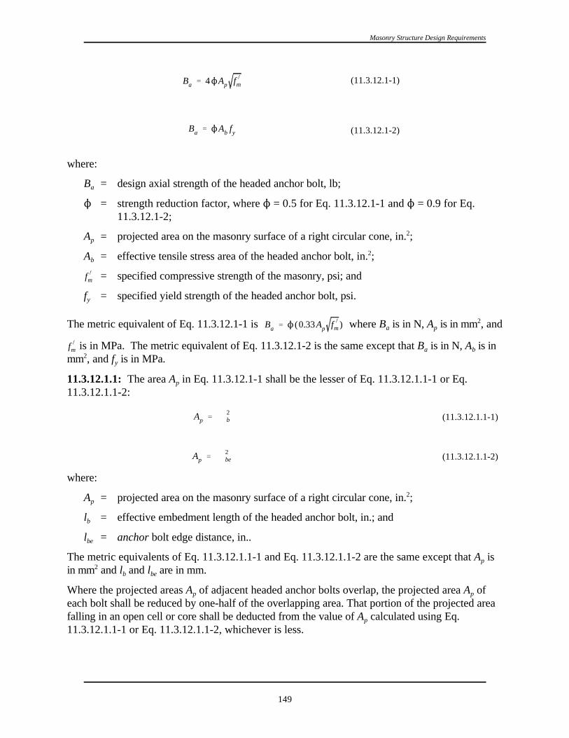
Ba ' 4NAp f )m
Ba ' NAb fy
Ap ' B R2b
Ap ' B R2be
f )m
Ba ' N (0.33Ap f )m )
f )m
Masonry Structure Design Requirements
149
(11.3.12.1-1)
(11.3.12.1-2)
(11.3.12.1.1-1)
(11.3.12.1.1-2)
where:
B = design axial strength of the headed anchor bolt, lb;a
N = strength reduction factor, where N = 0.5 for Eq. 11.3.12.1-1 and N = 0.9 for Eq.11.3.12.1-2;
A = projected area on the masonry surface of a right circular cone, in. ;p2
A = effective tensile stress area of the headed anchor bolt, in. ;b2
= specified compressive strength of the masonry, psi; and
f = specified yield strength of the headed anchor bolt, psi.y
The metric equivalent of Eq. 11.3.12.1-1 is where B is in N, A is in mm , anda p2
is in MPa. The metric equivalent of Eq. 11.3.12.1-2 is the same except that B is in N, A is ina b
mm , and f is in MPa.2y
11.3.12.1.1: The area A in Eq. 11.3.12.1-1 shall be the lesser of Eq. 11.3.12.1.1-1 or Eq.p
11.3.12.1.1-2:
where:
A = projected area on the masonry surface of a right circular cone, in. ;p2
l = effective embedment length of the headed anchor bolt, in.; and b
l = anchor bolt edge distance, in..be
The metric equivalents of Eq. 11.3.12.1.1-1 and Eq. 11.3.12.1.1-2 are the same except that A isp
in mm and l and l are in mm.2b be
Where the projected areas A of adjacent headed anchor bolts overlap, the projected area A ofp p
each bolt shall be reduced by one-half of the overlapping area. That portion of the projected areafalling in an open cell or core shall be deducted from the value of A calculated using Eq.p
11.3.12.1.1-1 or Eq. 11.3.12.1.1-2, whichever is less.

Ba ' 4NAp f )m
Ba ' 1.5N f )m edb % 200B lb % e % db db
Ba ' NAb fy
Ba ' 0.33NAp f )m
f )m
1997 Provisions, Chapter 11
150
(11.3.12.2-1)
(11.3.12.2-3)
(11.3.12.2-2)
11.3.12.1.2: The effective embedment length of a headed bolt, l , shall be the length ofb
embedment measured perpendicular from the surface of the masonry to the head of the anchorbolt.
11.3.12.1.3: The minimum effective embedment length of headed anchor bolts resisting axialforces shall be 4 bolt diameters or 2 in. (51 mm), whichever is greater.
11.3.12.2: The design axial strength, B for bent-bar anchor bolts (J- or L-bolts) embedded ina,
masonry shall be the least of Eq. 11.3.12.2-1 (strength governed by masonry breakout), Eq.11.3.12.2-2 (strength governed by steel), and Eq. 11.3.12.2-3 (strength governed by anchorpullout):
where:
B = design axial strength of the bent-bar anchor bolt, lb;a
N = strength reduction factor, where N = 0.5 for Eq. 11.3.12.2-1, N = 0.9 for Eq.11.3.12.2-2, and N = 0.65 for Eq. 11.3.12.2-3;
A = projected area on the masonry surface of a right circular cone, in. ;p2
A = effective tensile stress area of the bent-bar anchor bolt, in. ;b2
e = projected leg extension of bent-bar anchor bolt, measured from inside edge of anchorat bend to farthest point of anchor in the plane of the hook, in.; shall not be takenlarger than 2d for use in Equation 11.3.12.2-3.b
d = nominal diameter of bent-bar anchor bolt, in.b
l = effective embedment length of bent-bar anchor bolt, in.b
= specified compressive strength of the masonry, psi;
f = specified yield strength of the bent-bar anchor bolt, psi.y
The metric equivalent of Eq. 11.3.12.2-1 is:

Ba ' 1.5N f )medb % 2.05B(lb % e % db)db
Ap ' B l 2b
Ap ' B l 2be
Bv ' 1750N4
f )m Ab
Bv ' 0.6NAb fy
f )m
f )m
Masonry Structure Design Requirements
151
(11.3.12.2.1-1)
(11.3.12.2.1-2)
(11.3.12.3-1)
(11.3.12.3-2)
where B is in N, A is in mm , and is in MPa. The metric equivalent of Eq. 11.3.12.2-2 is thea p2
same except that B is in N, A is in mm , and f is in MPa. The metric equivalent of Eq.a b y2
11.3.12.2-3 is:
where B is in N, e and d are in mm, and is in MPa. The second term in Eq. 11.3.12.2-3 shalla b
be included only if continuous special inspection is provided during placement per Sec. 11.3.5.2.
11.3.12.2.1: The area A in Eq. 11.3.12.2-1 shall be the lesser of Eq.11.3.12.2.1-1 or Eq.p
11.3.12.2.1-2:
where:
A = projected area on the masonry surface of a right circular cone, in. ;p2
l = effective embedment length of the bent-bar anchor bolt, in.; and b
l = anchor bolt edge distance, in..be
The metric equivalents of Eq. 11.3.12.2.1-1 and Eq. 11.3.12.2.1-2 are the same except that A isp
in mm and l and l are in mm.2b be
Where the projected areas A of adjacent bent-bar anchor bolts overlap, the projected area A ofp p
each bolt shall be reduced by one-half of the overlapping area. That portion of the projected areafalling in an open cell or core shall be deducted from the value of A calculated using Eq.p
11.3.12.2.1-1 or Eq. 11.3.12.2.1-2, whichever is less.
11.3.12.2.2: The effective embedment of a bent-bar anchor bolt, l , shall be the length ofb
embedment measured perpendicular from the surface of the masonry to the bearing surface of thebent end, minus one anchor bolt diameter.
11.3.12.2.3: The minimum effective embedment length of bent-bar anchor bolts resisting axialforces shall be 4 bolt diameters or 2 in. (51 mm), whichever is greater.
11.3.12.3: Where the anchor bolt edge distance, l , equals or exceeds 12 bolt diameters, thebe
design shear strength, (B ), shall be the lesser of the values given by Eq. 11.3.12.3-1 (strengthv
governed by masonry) or Eq. 11.3.12.3-2 (strength governed by steel):

ba
Ba
%bv
Bv
# 1
f )m
Bv ' 5350N4
f )m Ab f )m
1997 Provisions, Chapter 11
152
(11.3.12.4)
where:
N = strength reduction factor, where N = 0.5 for Eq. 11.3.12.3-1 and N = 0.9 for Eq.11.3.12.3-2;
A = effective tensile stress area of the anchor bolt, in. ;b2
= specified compressive strength of the masonry, psi, and
f = specified yield strength of anchor bolt as applicable, psi.y
The metric equivalent of Eq. 11.3.12.3-1 is where A is in mm and and fb y2
are in MPa. The metric equivalent of Eq. 11.3.12.3-2 is the same as that above except that A isb
in mm and f is in MPa.2y
Where the anchor bolt edge distance, l , is less than 12 bolt diameters, the value of B in Eq.be v
11.3.12.3-1 shall be reduced by linear interpolation to zero at an l distance of 1 in. (25 mm).be
11.3.12.4: Anchor bolts subjected to combined shear and tension shall be designed to satisfy Eq.11.3.12.4:
where:
b = design axial force on the anchor bolt, lb (N);a
B = design axial strength of the anchor bolt, lb (N); a
b = design shear force on the anchor bolt, lb (N); and v
B = design shear strength of the anchor bolt, lb (N).v
11.4 DETAILS OF REINFORCEMENT:
11.4.1 General:
11.4.1.1: Details of reinforcement shall be shown on the contract documents.
11.4.1.2: Reinforcing bars shall be embedded in grout.
11.4.2 Size of Reinforcement:
11.4.2.1: Reinforcing bars used in masonry shall not be larger than a No. 9 bar (29 mm diameter).The bar diameter shall not exceed one-eighth of the nominal wall thickness and shall not exceed one-quarter of the least clear dimension of the cell, course, or collar joint in which it is placed. The area of reinforcing bars placed in a cell, or in a course, of hollow unit construction shall not exceed 4 percentof the cell area.
11.4.2.2: Longitudinal and cross wire joint reinforcement shall be a minimum W1.1, (0.011 mm ) and2
shall not exceed one-half the joint thickness.

ld '1N
0.15d 2b fy
K f )m
#52db
N
Masonry Structure Design Requirements
153
(11.4.5.2)
11.4.3 Placement Limits for Reinforcement:
11.4.3.1: The clear distance between parallel reinforcing bars shall not be less than the nominaldiameter of the bars nor less than 1 in. (25 mm).
11.4.3.2: In columns and pilasters, the clear distance between vertical reinforcing bars shall not be lessthan one and one-half times the nominal bar diameter, nor less than 1-1/2 in. (38 mm).
11.4.3.3: The clear distance limitations between reinforcing bars shall also apply to the clear distancebetween a contact lap splice and adjacent splices or bars.
11.4.3.4: Reinforcing bars shall not be bundled.
11.4.4 Cover for Reinforcement:
11.4.4.1: Reinforcing bars shall have a minimum thickness of masonry and grout cover not less than 2-1/2 d nor less than the following:b
a. Where the masonry face is exposed to earth or weather, 2 in. (51 mm) for bars larger than No. 5(16 mm) and 1-1/2 in. (38 mm) for No. 5 (16 mm) bar or smaller.
b. Where the masonry is not exposed to earth or weather, 1-1/2 in. (38 mm).
11.4.4.2: The minimum grout thickness between reinforcing bars and masonry units shall be 1/4 in. (6mm) for fine grout or 1/2 in. (12 mm) for coarse grout.
11.4.4.3: Longitudinal wires of joint reinforcement shall be fully embedded in mortar or grout with aminimum cover of 1/2 in. (13 mm) when exposed to earth or weather and 3/8 in. (10 mm) when notexposed to earth or weather. Joint reinforcement in masonry exposed to earth or weather shall becorrosion resistant or protected from corrosion by coating.
11.4.4.4: Wall ties, anchors, and inserts, except anchor bolts not exposed to the weather or moisture,shall be protected from corrosion.
11.4.5 Development of Reinforcement:
11.4.5.1 General: The calculated tension or compression in the reinforcement where masonryreinforcement is anchored in concrete shall be developed in the concrete by embedment length, hook ormechanical device or a combination thereof. Hooks shall only be used to develop bars in tension.
11.4.5.2 Embedment of Reinforcing Bars and Wires in Tension: The embedment length, l , ofd
reinforcing bars and wire shall be determined by Eq. 11.4.5.2 but shall not be less than 12 in. (305 mm)for bars and 6 in. (152 mm) for wire:
where:
N = strength reduction factor as given in Table 11.5.3;
d = diameter of the reinforcement, in.;b

ldh ' 13db
f )m
ld '1N
1.8d 2b fy
K f )m
#52db
N
1997 Provisions, Chapter 11
154
(11.4.5.3.2)
K = the lesser of the clear spacing between adjacent reinforcement, or 3 times d , in.;b
= specified compressive strength of masonry, psi; and
f = specified yield strength of the reinforcement, psi.y
The metric equivalent of Eq. 11.4.5.2 is where l and d are in mm and fd b y
and f are in MPa.m
11.4.5.3 Standard Hooks:
11.4.5.3.1: The term standard hook as used in this code shall mean one of the following:
11.4.5.3.1.1: A 180-degree turn plus extension of at least 4 bar diameters but not less than 2-1/2 in.(64 mm) at free end of bar.
11.4.5.3.1.2: A 135-degree turn plus extension of at least 6 bar diameters at free end of bar.
11.4.5.3.1.3: A 90-degree turn plus extension of at least 12 bar diameters at free end of bar.
11.4.5.3.1.4: For stirrup and tie anchorage only, either a 135-degree or a 180- degree turn plus anextension of at least 6 bar diameters at the free end of the bar.
11.4.5.3.2: The equivalent embedment length for standard hooks in tension, l , shall be as follows:dh
where d = diameter of the reinforcement, in. The metric equivalent of Eq. 11.4.5.3.2 is the sameb
except that d is in mm.b
11.4.5.3.3: The effect of hooks for bars in compression shall be neglected in design computations.
11.4.5.4 Minimum Bend Diameter for Reinforcing Bars:
11.4.5.4.1: The diameter of bend measured on the inside of the bar, other than for stirrups and ties,shall not be less than values specified in Table 11.4.5.4.1.
TABLE 11.4.5.4.1 Minimum Diameters of Bend
Bar Size Grade MinimumBend
No. 3 (10 mm) through No. 7 (22 mm) 40 5 bar diametersNo. 3 (10 mm) through No. 8 (25 mm) 50 or 60 6 bar diametersNo. 9 (29 mm) 50 or 60 8 bar diameters
11.4.5.5 Development of Shear Reinforcement:
11.4.5.5.1: Shear reinforcement shall extend the depth of the member less cover distances.
11.4.5.5.2: The ends of single leg or U-stirrups shall be anchored by one of the following means:

Masonry Structure Design Requirements
155
a. A standard hook plus an effective embedment of 0.5 times the development length, l . Thed
effective embedment of a stirrup leg shall be taken as the distance between the mid-depth of themember, and the start of the hook (point of tangency).
b. For No. 5 (16 mm) bar and D31 wire and smaller, bending around longitudinal reinforcementthrough at least 135 degrees plus an embedment of l /3 . The l /3 embedment of a stirrup leg shalld d
be taken as the distance between mid-depth of member, and the start of the hook (point oftangency).
c. Between the anchored ends, each bend in the continuous portion of a transverse U-stirrup shallenclose a longitudinal bar.
11.4.5.5.3: Except at wall intersections, the end of a reinforcing bar needed to satisfy shear strengthrequirements in accordance with Sec. 11.7.3.3 shall be bent around the edge vertical reinforcing barwith a 180-degree hook. At wall intersections, reinforcing bars used as shear reinforcement shall bebent around the edge vertical bar with a 90-degree standard hook and shall extend horizontally into theintersecting wall.
11.4.5.6 Splices of Reinforcement: Lap splices, welded splices, or mechanical connections shall bein accordance with the provisions of this section.
11.4.5.6.1 Lap Splices: Lap splices shall not be used in plastic hinge zones. The length of the plastichinge zone shall be taken as at least 0.15 times the distance between the point of zero moment and thepoint of maximum moment.
11.4.5.6.1.1: The minimum length of lap, l , for bars in tension or compression shall be equal to theld
development length, l , as determined by Eq. 11.4.5.2 but shall not be less than 12 in. (305 mm) ford
bars and 6 in (152 mm) for wire.
11.4.5.6.1.2: Bars spliced by noncontact lap splices shall not be spaced transversely farther apart thanone-fifth the required length of lap nor more than 8 in. (203 mm).
11.4.5.6.2 Welded Splices: A welded splice shall be capable of developing in tension 125 percent ofthe specified yield strength, f , of the bar.y
11.4.5.6.3 Mechanical Connections: Mechanical splices shall have the bars connected to develop intension or compression, as required, at least 125 percent of the specified yield strength of the bar.
11.4.5.6.4 End Bearing Splices:
11.4.5.6.4.1: In bars required for compression only, the transmission of compressive stress by bearingof square cut ends held in concentric contact by a suitable device is permitted.
11.4.5.6.4.2: Bar ends shall terminate in flat surfaces within 1-1/2 degrees of a right angle to the axisof the bars and shall be fitted within 3 degrees of full bearing after assembly.
11.4.5.6.4.3: End bearing splices shall be used only in members containing closed ties, closed stirrupsor spirals.

1997 Provisions, Chapter 11
156
11.5 STRENGTH AND DEFORMATION REQUIREMENTS:
11.5.1 General: Masonry structures and masonry members shall be designed to have strength at allsections at least equal to the required strength calculated for the factored loads in such combinations asare stipulated in these provisions.
11.5.2 Required Strength: The required strength shall be determined in accordance with Chapters 2and 3.
11.5.3 Design Strength: Design strength provided by a member and its connections to othermembers and its cross sections in terms of flexure, axial load, and shear shall be taken as the nominalstrength multiplied by a strength reduction factor, N, as specified in Table 11.5.3.

Ieff ' In
Mcr
Ma
3
% Icr 1&Mcr
Ma
3
< In
Masonry Structure Design Requirements
157
(11.5.4.3)
TABLE 11.5.3 Strength Reduction Factor NNAxial Load, Flexure, and Reinforced masonry N = 0.85Combinations of Axial Plain masonry N = 0.60Load and Flexure
Shear Reinforced masonry N = 0.80
Shear Plain masonry N = 0.80
Reinforcement development length and splices N = 0.80
Anchor bolt strength as governed by steel N = 0.90
Anchor bolt strength as governed by masonry N = 0.50
Bearing N = 0.60
11.5.4 Deformation Requirements:
11.5.4.1: Masonry structures shall be designed so the design story drift, ), does not exceed theallowable story drift, ) , obtained from Table 5.2.8.a
11.5.4.1.1: Cantilever shear walls shall be proportioned such that the maximum displacement, * , atmax
Level n does not exceed 0.01h .n
11.5.4.2: Deflection calculations for plain masonry members shall be based on uncracked sectionproperties.
11.5.4.3: Deflection calculations for reinforced masonry members shall be based on an effectivemoment of inertia in accordance with the following:
where:
M = Sf ;cr r
M = cracking moment strength of the masonry, in.-lb;cr
M = maximum moment in the member at the stage deflection is computed, in.-lb;a
I = moment of inertia of the cracked section, in. ;cr4
I = moment of inertia of the net cross-sectional area of the member, in. ;n4
S = uncracked section modulus of the wall, in. ; and3
f = modulus of rupture of masonry, psi.r
The metric equivalent of Eq. 11.5.4.3 is the same except that M and M are in (N-mm), I and I arecr a cr n
in mm , S is in mm , and f is in MPa.4 3r
11.5.4.4: The calculated deflection shall be multiplied by C for determining drift.d
11.6 FLEXURE AND AXIAL LOADS:

f )m
1997 Provisions, Chapter 11
158
11.6.1 Scope8.6.1 SCOPE: This section shall apply to the design of masonry members subject toflexure or axial loads or to combined flexure and axial loads.
11.6.2 Design Requirements of Reinforced Masonry Members:
11.6.2.1: Strength design of members for flexure and axial loads shall be in accordance with principlesof engineering mechanics, and in accordance with the following design assumptions:
a. Strain in reinforcement and masonry shall be assumed directly proportional to the distance from theneutral axis, except for deep flexural members with overall depth to clear span ratio greater than2/5 for continuous span members and 4/5 for simple span members where a nonlinear distributionof strain shall be considered.
b. Maximum usable strain, ε , at the extreme masonry compression fiber shall be assumed equal tomu
0.0025 for concrete masonry and 0.0035 for clay-unit masonry.
c. Stress in reinforcement below the specified yield strength, f , shall be taken as the modulus ofy
elasticity, E , times the steel strain. For strains greater than those corresponding to the specifieds
yield strength, f , the stress in the reinforcement shall be considered independent of strain and equaly
to the specified yield strength, f ,y
d. Tensile strength of masonry shall be neglected in calculating the flexural strength of a reinforcedmasonry cross section.
e. Flexural compression in masonry shall be assumed to be an equivalent rectangular stress block. Masonry stress of 0.80 times the specified compressive strength, shall be assumed to beuniformly distributed over an equivalent compression zone bounded by edges of the cross sectionand a straight line located parallel to the neutral axis at a distance a = 0.80 c from the fiber ofmaximum compressive strain.
11.6.2.2: The ratio of reinforcement, ρ, shall not exceed the lesser ratio as calculated with either of thefollowing two that will cause the following critical strain conditions
1. For walls subjected to in-plane forces, columns and beams, the critical strain condition correspondsto a strain in the extreme tension reinforcement equal to 5 times the strain associated with thereinforcement yield stress, f .y
2. For walls subjected to out-of-plane forces, the critical strain condition corresponds to a strain in theextreme tension reinforcement equal to 1.3 times the strain associated with the reinforcement yieldstress, f .y
For both cases, the strain at the extreme compression fiber shall be assumed to be either 0.0035 in./in.for clay masonry or 0.0025 in./in. for concrete masonry.
The calculation of the maximum reinforcement ratio shall include unfactored gravity axial loads. Thestress in the tension reinforcement shall be assumed to be 1.25f . Tension in the masonry shall bey
neglected. The strength of the compressive zone shall be calculated as 80 percent of f times 80m’
percent of the area of the compressive zone. Stress in reinforcement in the compression zone shall bebased on a linear strain distribution.

NPn ' NAn f )m 1 &h
140r
2
for h/r < 99
NPn ' NAn f )m70rh
2for h/r $ 99
Vu # NVn
f )m
f )m
f )m
Masonry Structure Design Requirements
159
(11.6.3.5-1)
(11.6.3.5-2)
(11.7.2.1)
11.6.2.3: Members subject to compressive axial load shall be designed for the maximum moment thatcan accompany the axial load. The required moment, M , shall include the moment induced by relativeu
lateral displacements.
11.6.3 Design of Plain (Unreinforced) Masonry Members:
11.6.3.1: Strength design of members for flexure and axial load shall be in accordance with principlesof engineering mechanics .
11.6.3.2: Strain in masonry shall be assumed directly proportional to the distance from the neutralaxis.
11.6.3.3: Flexural tension in masonry shall be assumed directly proportional to strain.
11.6.3.4: Flexural compressive stress in combination with axial compressive stress in masonry shall beassumed directly proportional to strain. Maximum compressive stress shall not exceed 0.85 .
11.6.3.5: Design axial load strength shall be in accordance with Eq. 11.6.3.5-1 or Eq. 11.6.3.5-2:
where:
N = strength reduction factor per Table 11.5.3;
A = net cross-sectional area of the masonry, in. ;n2
= specified compressive strength of the masonry, psi;
h = effective height of the wall between points of support, in. and
r = radius of gyration, inches.
The metric equivalents for Eq. 11.6.3.5-1 and Eq. 11.6.3.5-2 are the same except that A is in mm , n2
is in MPa, and h and r are in mm.
11.7 SHEAR:
11.7.1 Scope: Provisions of this section shall apply for design of members subject to shear.
11.7.2 Shear Strength:
11.7.2.1: Design of cross sections subjected to shear shall be based on:
where:
V = required shear strength due to factored loads, lb.u
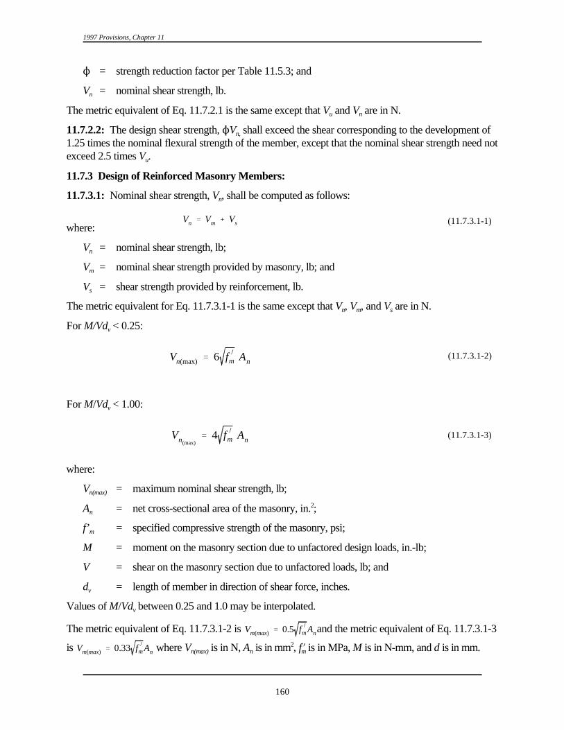
Vn ' Vm % Vs
Vn(max) ' 6 f )m An
Vn(max)' 4 f )m An
Vm(max) ' 0.5 f )m An
Vm(max) ' 0.33 f )m An
1997 Provisions, Chapter 11
160
(11.7.3.1-1)
(11.7.3.1-2)
(11.7.3.1-3)
N = strength reduction factor per Table 11.5.3; and
V = nominal shear strength, lb.n
The metric equivalent of Eq. 11.7.2.1 is the same except that V and V are in N.u n
11.7.2.2: The design shear strength, NV shall exceed the shear corresponding to the development of n,
1.25 times the nominal flexural strength of the member, except that the nominal shear strength need notexceed 2.5 times V .u
11.7.3 Design of Reinforced Masonry Members:
11.7.3.1: Nominal shear strength, V , shall be computed as follows:n
where:
V = nominal shear strength, lb;n
V = nominal shear strength provided by masonry, lb; and m
V = shear strength provided by reinforcement, lb.s
The metric equivalent for Eq. 11.7.3.1-1 is the same except that V , V , and V are in N.n m s
For M/Vd < 0.25:v
For M/Vd < 1.00:v
where:
V = maximum nominal shear strength, lb;n(max)
A = net cross-sectional area of the masonry, in. ;n2
f’ = specified compressive strength of the masonry, psi;m
M = moment on the masonry section due to unfactored design loads, in.-lb;
V = shear on the masonry section due to unfactored loads, lb; and
d = length of member in direction of shear force, inches.v
Values of M/Vd between 0.25 and 1.0 may be interpolated.v
The metric equivalent of Eq. 11.7.3.1-2 is and the metric equivalent of Eq. 11.7.3.1-3
is where V is in N, A is in mm , fN is in MPa, M is in N-mm, and d is in mm.n(max) n m2
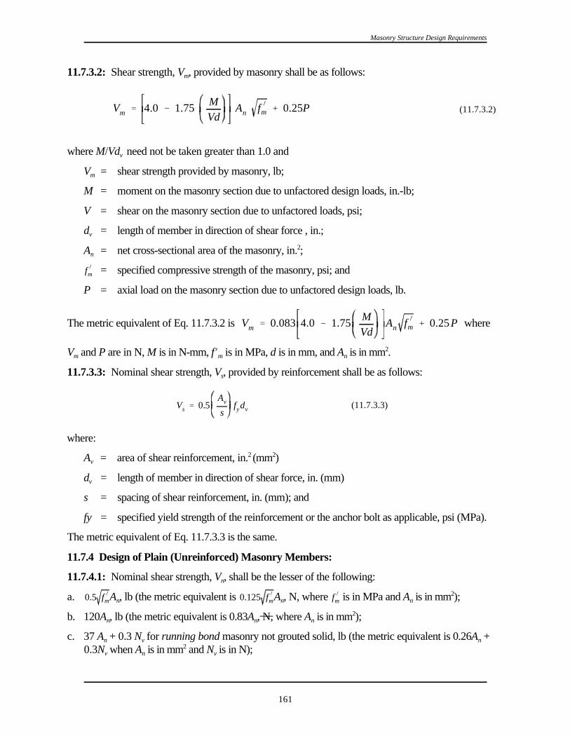
Vm ' 4.0 & 1.75MVd
An f )m % 0.25P
Vs ' 0.5Av
sfydv
f )m
Vm ' 0.083 4.0 & 1.75MVd
An f )m % 0.25P
0.5 f )m 0.125 f )m f )m
Masonry Structure Design Requirements
161
(11.7.3.2)
(11.7.3.3)
11.7.3.2: Shear strength, V , provided by masonry shall be as follows:m
where M/Vd need not be taken greater than 1.0 andv
V = shear strength provided by masonry, lb;m
M = moment on the masonry section due to unfactored design loads, in.-lb;
V = shear on the masonry section due to unfactored loads, psi;
d = length of member in direction of shear force , in.;v
A = net cross-sectional area of the masonry, in. ;n2
= specified compressive strength of the masonry, psi; and
P = axial load on the masonry section due to unfactored design loads, lb.
The metric equivalent of Eq. 11.7.3.2 is where
V and P are in N, M is in N-mm, fN is in MPa, d is in mm, and A is in mm .m m n2
11.7.3.3: Nominal shear strength, V , provided by reinforcement shall be as follows:s
where:
A = area of shear reinforcement, in. (mm )v2 2
d = length of member in direction of shear force, in. (mm)v
s = spacing of shear reinforcement, in. (mm); and
fy = specified yield strength of the reinforcement or the anchor bolt as applicable, psi (MPa).
The metric equivalent of Eq. 11.7.3.3 is the same.
11.7.4 Design of Plain (Unreinforced) Masonry Members:
11.7.4.1: Nominal shear strength, V , shall be the lesser of the following:n
a. A , lb (the metric equivalent is A , N, where is in MPa and A is in mm );n n n2
b. 120A , lb (the metric equivalent is 0.83A , N, where A is in mm );n n n2
c. 37 A + 0.3 N for running bond masonry not grouted solid, lb (the metric equivalent is 0.26A +n v n
0.3N when A is in mm and N is in N);v n v2

f )m
1997 Provisions, Chapter 11
162
37 A + 0.3 N for stack bond masonry with open end units and grouted solid, lb (the metricn v
equivalent is 0.26A + 0.3N when A is in mm and N is in N);n v n v2
60 A + 0.3 N for running bond masonry grouted solid, lb (the metric equivalent is 0.414A +n v n
0.3N when A is in mm and N is in N); andv n v2
15 A for stack bond other than open end units grouted solid, lb (the metric equivalent is 0.103A +n n
0.3N when A is in mm and N is in N)v n v2
where:
= specified compressive strength of the masonry, psi;
A = net cross-sectional area of the masonry, in. ; andn2
N = force acting normal to shear surface, lb.v
11.8 SPECIAL REQUIREMENTS FOR BEAMS:
11.8.1: The spacing between lateral supports shall be determined by the requirements for out of-planeloading, but it shall not exceed 32 times the least width of beam.
11.8.2: The effects of lateral eccentricity of load shall be taken into account in determining spacing oflateral supports.
11.8.3: The minimum positive reinforcement ratio ρ in a beam shall not be less than 120/f (the metricy
equivalent is 0.83/f where f is in MPa) except that this minimum positive steel reinforcement ratioy y
need not be satisfied if the area of reinforcement provided is one third greater than that required byanalysis for gravity loads and the Seismic Design Category is A, B, or C.
Where a concrete floor provides a flange and where the beam web is in tension, the ratio D shall becomputed using the web width.
11.8.4 Deep Flexural Members:
11.8.4.1: Flexural members with overall depth to clear span ratios greater than 2/5 for continuousspans or 4/5 for simple spans shall be designed as deep flexural members taking into account nonlineardistribution of strain and lateral buckling.
11.8.4.2: Minimum flexural tension reinforcement shall conform to Sec. 11.8.3.
11.8.4.3: Uniformly distributed horizontal and vertical reinforcement shall be provided throughout thelength and depth of deep flexural members such that the reinforcement ratios in both directions are atleast 0.001. Distributed flexural reinforcement is to be included in the determination of the actualreinforcement ratios.
11.9 SPECIAL REQUIREMENTS FOR COLUMNS:
11.9.1: Area of longitudinal reinforcement for columns shall be not less than 0.005 nor more than 0.04times cross-sectional area of the column.
11.9.2: There shall be a minimum of four longitudinal bars in columns.
11.9.3: Lateral ties shall be provided to resist shear and shall comply with the following:

Masonry Structure Design Requirements
163
a. Lateral ties shall be at least 1/4 in. (6 mm) in diameter.
b. Vertical spacing of lateral ties shall not exceed 16 longitudinal bar diameters, 48 lateral tiediameters, nor the least cross sectional dimension of the column.
c. Lateral ties shall be arranged such that every corner and alternate longitudinal bar shall have lateralsupport provided by the corner of a lateral tie with an included angle of not more than 135 degreesand no bar shall be farther than 6 in. (152 mm) clear on each side along the lateral tie from such alaterally supported bar. Lateral ties shall be placed in either a mortar joint or grout. Wherelongitudinal bars are located around the perimeter of a circle, a complete circular lateral tie ispermitted. Minimum lap length for circular ties shall be 84 tie diameters.
d. Lateral ties shall be located vertically not more than one-half lateral tie spacing above the top offooting or slab in any story and shall be spaced as provided herein to not more than one-half alateral tie spacing below the lowest horizontal reinforcement in beam, girder, slab or drop panelabove.
e. Where beams or brackets frame into a column from four directions, lateral ties may be terminatednot more than 3 in. (76 mm) below lowest reinforcement in the shallowest of such beams orbrackets.
11.10 SPECIAL REQUIREMENTS FOR WALLS:
11.10.1: The nominal flexural strength of the wall for out-of-plane flexure shall be at least equal to 1.3times the cracking moment strength of the wall.
11.11 SPECIAL REQUIREMENTS FOR SHEAR WALLS:
11.11.1 Ordinary Plain Masonry Shear Walls: The design of ordinary plain masonry shear wallsshall be in accordance with Sec. 11.3.2 or Sec. 11.3.3. No reinforcement is required to resist seismicforces.
11.11.2 Detailed Plain Masonry Shear Walls: The design of detailed plain masonry shear wallsshall be in accordance with Sec. 11.3.3. Detailed plain masonry shear walls shall have minimumamounts of reinforcement as prescribed in Sections 11.3.7.3 and 11.3.7.4.
11.11.3 Ordinary Reinforced Masonry Shear Walls: The design of ordinary reinforced masonryshear walls shall be in accordance with Sec. 11.3.4. No prescriptive seismic reinforcement is requiredfor ordinary reinforced masonry shear walls
11.11.4 Intermediate Reinforced Masonry Shear Walls: The design of intermediate reinforcedmasonry shear walls shall be in accordance with Sec. 11.3.4. Intermediate reinforced masonry shearwalls shall have minimum amounts of reinforcement as prescribed in Sec. 11.3.7.3 and 11.3.7.4.
11.11.5 Special Reinforced Masonry Shear Walls: Special reinforced masonry shear walls shallmeet the requirements for intermediate reinforced masonry shear walls (Sec. 11.11.4) in addition tothe requirements of this section.
The design of special reinforced masonry shear walls shall be in accordance with Sec. 11.3.4. Specialreinforced masonry shear walls shall comply with material requirements of Sec. 11.3.8, minimumreinforcement requirements of Sec. 11.3.8.3 and 11.3.8.4, and minimum thickness requirements of Sec.

1997 Provisions, Chapter 11
164
11.3.8.5. In addition, special reinforced masonry shear walls shall be reinforced and constructed asrequired in this section.
11.11.5.1 Vertical Reinforcement: The maximum spacing of vertical reinforcement in an specialreinforced masonry shear wall shall be the smaller of::
a. One-third the length of the wall
b. One-third the height of the wall
c. 48 in. (1219 mm).
11.11.5.2 Horizontal Reinforcement: Reinforcement required to resist in-plane shear in a specialreinforced masonry shear wall shall be placed horizontally, shall be uniformly distributed, and shall beembedded in grout. The maximum spacing of horizontal reinforcement shall be the smaller of:
a. One-third the length of the wall
b. One-third the height of the wall
c. 48 in. (1219 mm)
d. 24 in. (610 mm) for stack bond masonry.
11.11.5.3 Shear Keys: The surface of concrete upon which an special reinforced masonry shearwall is constructed shall have a minimum surface roughness of 1/8 inch (3.0 mm). Keys with thefollowing minimum requirements shall be placed at the base of special reinforced masonry shear wallswhen the calculated strain in vertical reinforcement exceeds the yield strain under load combinationsthat include seismic forces based on a R factor equal to 1.5.
a. The width of the keys shall be at least equal to the width of the grout space
b. The depth of the keys shall be at least 1.5 inches (40 mm)
c. The length of the key shall be at least 6 inches (152 mm)
d. The spacing between keys shall be at least equal to the length of the key
e. The cumulative length of all keys shall be at least 20% of the length of the shear wall
f. A minimum of one key shall be placed within 16 inches (406 mm) of each end of a shear wall
g. Each key and the grout space above each key in the first course of masonry shall be grouted solid.
11.11.6: Flanged Shear Walls:
11.11.6.1: Wall intersections shall be considered effective in transferring shear when eitherconditions (a) or (b) and condition (c) as noted below aree met:
a. The face shells of hollow masonry units are removed and the intersection is fully grouted.
b. Solid units are laid in running bond and 50 percent of the masonry units at the intersection areinterlocked.
c. Reinforcement from one intersecting wall continues past the intersection a distance not less than 40bar diameters or 24 inches (600 mm).
Vn $M1 % M2
Lc
% Vg
Masonry Structure Design Requirements
165
(11.11.7.2)
11.11.6.2: The width of flange considered effective in compression on each side of the web shall betaken equal to 6 times the thickness of the web or shall be equal to the actual flange on either side ofthe web wall, whichever is less.
11.11.6.3: The width of flange considered effective in tension on each side of the web shall be takenequal to 3/4 of the wall height or shall be equal to the actual flange on either side of the web wall,whichever is less.
11.11.7 Coupled Shear Walls:
11.11.7.1 Design of Coupled Shear Walls: Structural members which provide coupling betweenshear walls shall be designed to reach their moment or shear nominal strength before either shear wallreaches its moment or shear nominal strength. Analysis of coupled shear walls shall conform toaccepted principles of mechanics.
11.11.7.2 Shear Strength of Coupling Beams: The nominal shear strength, V , of the couplingn
beams shall exceed the shear calculated:
where:
V = nominal shear strength, lb (N);n
M and M = nominal moment strength at the ends of the beam, lb-in. (N-mm); 1 2
L = length of the beam between the shear walls, in. (mm); and c
V = shear force due to gravity loads, lb (N).g
The metric equivalent of Eq. 11.11.5.2 is the same except that V and V are in N, M and M are in N-n g 1 2
mm, and L is in mm.c
The calculation of the nominal flexural moment shall include the reinforcement in reinforced concreteroof and floor system. The width of the reinforced concrete used for calculations of reinforcement shallbe six times the floor or roof slab thickness.
11.12 SPECIAL MOMENT FRAMES OF MASONRY:
11.12.1 Calculation of Required Strength: The calculation of required strength of the membersshall be in accordance with principles of engineering mechanics and shall consider the effects of therelative stiffness degradation of the beams and columns.
11.12.2 Flexural Yielding: Flexural yielding shall be limited to the beams at the face of the columnsand to the bottom of the columns at the base of the structure.
11.12.3 Reinforcement:
11.12.3.1: The nominal moment strength at any section along a member shall not be less than 1/2 ofthe higher moment strength provided at the two ends of the member.

f )m
1997 Provisions, Chapter 11
166
11.12.3.2: Lap splices are permitted only within the center half of the member length.
11.12.3.3: Welded splices and mechanical connections may be used for splicing the reinforcement atany section, provided not more than alternate longitudinal bars are spliced at a section, and the distancebetween splices on alternate bars is at least 24 in. (610 mm) along the longitudinal axis.
11.12.3.4: Reinforcement shall have a specified yield strength of 60,000 psi (414 MPa). The actualyield strength shall not exceed 1.5 times the specified yield strength.
11.12.4 Wall Frame Beams:
11.12.4.1: Factored axial compression force on the beam shall not exceed 0.10 times the net cross-sectional area of the beam, A , times the specified compressive strength, .n
11.12.4.2: Beams interconnecting vertical elements of the lateral-load-resisting system shall be limitedto a reinforcement ratio of 0.15f /f or that determined in accordance with Sec. 11.6.2.2. Allm y
’
reinforcement in the beam and adjacent to the beam in a reinforced concrete roof or floor system shallbe used to calculate the reinforcement ratio.
11.12.4.3: Clear span for the beam shall not be less than 4 times its depth.
11.12.4.4: Nominal depth of the beam shall not be less than 4 units or 32 in. (813 mm), whichever isgreater. The nominal depth to nominal width ratio shall not exceed 4.
11.12.4.5: Nominal width of the beams shall equal or exceed all of the following criteria:
a. 8 in. (203 mm),
b. width required by Sec. 11.8.1, and
c. 1/26 of the clear span between column faces.
11.12.4.6: Longitudinal Reinforcement:
11.12.4.6.1: Longitudinal reinforcement shall not be spaced more than 8 in. (203 mm) on center.
11.12.4.6.2: Longitudinal reinforcement shall be uniformly distributed along the depth of the beam.
11.12.4.6.3: In lieu of the limitations of Sec. 11.8.2, the minimum reinforcement ratio shall be 130/fy
(the metric equivalent is 0.90/f where f is in MPa).y y
11.12.4.6.4: At any section of a beam, each masonry unit through the beam depth shall containlongitudinal reinforcement.
11.12.4.7 Transverse Reinforcement:
11.12.4.7.1: Transverse reinforcement shall be hooked around top and bottom longitudinal bars andshall be terminated with a standard 180-degree hook.
11.12.4.7.2: Within an end region extending one beam depth from wall frame column faces and at anyregion at which beam plastic hinges may form during seismic or wind loading, maximum spacing oftransverse reinforcement shall not exceed one-fourth the nominal depth of the beam.
11.12.4.7.3: The maximum spacing of transverse reinforcement shall not exceed 1/2 the nominaldepth of the beam or that required for shear strength.

hp >4,800dbp
f )g
f )m
Masonry Structure Design Requirements
167
(11.12.6.1-1)
11.12.4.7.4: Minimum transverse reinforcement ratio shall be 0.0015.
11.12.4.7.5: The first transverse bar shall not be more than 4 inches (102 mm) from the face of thepier.
11.12.5 Wall Frame Columns:
11.12.5.1: Factored axial compression force on the wall frame column shall not exceed 0.15 times thenet cross-sectional area of the column, A , times the specified compressive strength, . Then
compressive stress shall also be limited by the maximum reinforcement ratio.
11.12.5.2: Nominal dimension of the column parallel to the plane of the wall frame shall not be lessthan two full units or 32 in. (810 mm), whichever is greater.
11.12.5.3: Nominal dimension of the column perpendicular to the plane of the wall frame shall not beless than 8 in. (203 mm) nor 1/14 of the clear height between beam faces.
11.12.5.4: The clear height-to-depth ratio of column members shall not exceed 5.
11.12.5.5 Longitudinal Reinforcement:
11.12.5.5.1: A minimum of 4 longitudinal bars shall be provided at all sections of every wall framecolumn member.
11.12.5.5.2: The flexural reinforcement shall be uniformly distributed across the member depth.
11.12.5.5.3: The nominal moment strength at any section along a member shall be not less than 1.6times the cracking moment strength and the minimum reinforcement ratio shall be 130/f (the metricy
equivalent is 0.90/f where f is in MPa).y y
11.12.5.5.4: Vertical reinforcement in wall-frame columns shall be limited to a maximumreinforcement ratio equal to the lesser of 0.15f / F or that determined in accordance with Sec.m y
11.6.2.2.
11.12.5.6 Transverse Reinforcement:
11.12.5.6.1: Transverse reinforcement shall be hooked around the extreme longitudinal bars and shallbe terminated with a standard 180-degree hook.
11.12.5.6.2: The spacing of transverse reinforcement shall not exceed 1/4 the nominal dimension ofthe column parallel to the plane of the wall frame.
11.12.5.6.3: Minimum transverse reinforcement ratio shall be 0.0015.
11.12.6 Wall Frame Beam-Column Intersection:
11.12.6.1: Beam-column intersection dimensions in masonry wall frames shall be proportioned suchthat the wall frame column depth in the plane of the frame satisfies Eq. 11.12.6.1-1:
where:

hb >1800dbp
f )g
As $0.5Vn
fy
hp >400dbb
f )g
f )g
hb >150dbp
f )g
f )g
1997 Provisions, Chapter 11
168
(11.12.7.1.2)
(11.12.6.2)
h = pier depth in the plane of the wall frame, in.;p
d = diameter of the largest beam longitudinal reinforcing bar passing through, or anchored in,bb
the wall frame beam-column intersection, in.; and
f’ = specified compressive strength of grout, psi (shall not exceed 5,000 psi (34.5 MPa) for useg
in Eq. 11.12.7.1-1).
The metric equivalent of Eq. 11.12.6.1-1 is where h and d are in mm and is in MPa.p bb
Beam depth in the plane of the frame shall satisfy Eq. 11.1.2.7.1-2:
where:
h = beam depth in the plane of the wall frame, in.;b
d = diameter of the largest column (pier) longitudinal reinforcing bar passing through, orbp
anchored in, the wall frame beam-column intersection, in.; and
f’ = specified compressive strength of grout, psi (shall not exceed 5,000 psi (34.2MPa) for useg
in Eq. 11.12.7.1-1).
The metric equivalent of Eq. 11.12.7.1-2 is where h and d are in mm and is inb bp
MPa.
Nominal shear strength of beam-column intersections shall exceed the shear occurring when wall framebeams develop their nominal flexural strength.
11.12.6.2: Beam longitudinal reinforcement terminating in a wall frame column shall be extended tothe far face of the column and shall be anchored by a standard hook bent back into the wall framecolumn.
Special horizontal shear reinforcement crossing a potential diagonal beam column shear crack shall beprovided such that:
where:
A = cross-sectional area of reinforcement in. ;s2
V = nominal shear strength, lb; andn

7 f )m 0.58 f )m
Masonry Structure Design Requirements
169
f = specified yield strength of the reinforcement or the anchor bolt as applicable, psi.y
The metric equivalent of Eq. 11.12.7.2 is the same except that A is in mm , V is in N, and f is in MPa.s n y2
Special horizontal shear reinforcement shall be anchored by a standard hook around the extreme wallframe column reinforcing bars.
Vertical shear forces may be considered to be carried by a combination of masonry shear-resistingmechanisms and truss mechanisms involving intermediate column reinforcing bars.
The nominal horizontal shear stress at the beam-column intersection shall not exceed the lesser of 350psi (2.5 MPa) or (the metric equivalent is MPa).
11.13 GLASS-UNIT MASONRY AND MASONRY VENEER:
11.13.1 Design Lateral Forces and Displacements: Glass-unit masonry and masonry veneer shallbe designed and detailed to resist the design lateral forces as described in Sec. 6.1 and 6.2.
11.13.2 Glass-Unit Masonry Design:
11.13.2.1: The requirements of Chapter 11 of Ref. 11-1 shall apply to the design of glass unitmasonry. The out-of-plane seismic strength shall be considered as the same as the strength to resistwind pressure as specified in Sec. 11.3 of Ref. 11-1.
11.13.3 Masonry Veneer Design:
11.13.3.1: The requirements of Chapter 12 of Ref. 11-1 shall apply to the design of masonry veneer.
11.13.3.2: For structures in Seismic Design Category E, corrugated sheet metal anchors shall not beused.

170
Appendix to Chapter 11
ALTERNATIVE PROVISIONS FOR THE DESIGN OFMASONRY STRUCTURES
11A.1 GENERAL8A.1 GENERAL:
11A.1.1 Scope: The provisions of this chapter for the design and construction of reinforced andplain (unreinforced) masonry components and systems shall be permitted as an alternative to theprovisions of Chapter 11. The seismic design requirements of this appendix chapter apply to the designof masonry and the construction of masonry structural elements, except glass unit masonry andmasonry veneers, in all Seismic Design Categories.
11A.1.2 Reference Document: The design, construction, and quality assurance of masonrycomponents designed in accordance with the alternative masonry provisions of this appendix chaptershall conform to the requirements of Ref. 11A-1 except as modified herein:
Ref. 11A-1 Building Code Requirements for Masonry Structures, ACI 530-95/ASCE 5-95/TMS 402-95, and Specification for Masonry Structures, ACI 530.1-95/ASCE 6-95/TMS 602-95.
11A.1.2.1 Modifications to Chapter 10 of Ref. 11A-1:
11A.1.2.1.1: The requirements of Sec. 10.1.1 and 10.2.1 of Ref. 11A-1 shall not apply.
11A1.2.1.2: Masonry structures and masonry elements shall comply with the requirements of Sec.10.2.2 of Ref. 11A-1 with the exception that Sec. 10.2.2.1 shall not apply. In addition, masonrystructures and masonry elements shall comply with the requirements of Sec. 10.3 through 10.7 of Ref.11A-1. Requirements for Seismic Design Categories A, B, C, D and E as defined in Sec. 1.4.4 shall bethe same as requirements for Seismic Performance Categories as described in Chapter 10 of Ref. 11A-1.
11A.1.2.1.3: Required strength to resist seismic forces in combinations with gravity and other loadsshall be as required in Sec. 5.2.7. Nonbearing masonry walls shall be designed for the seismic forceapplied perpendicular to the plane of the wall and uniformly distributed over the wall area.
11A.2 RESPONSE MODIFICATION COEFFICIENTS8A.3 RESPONSE MODIFICATIONCOEFFICIENTS: The response modification coefficients, R, of Table 5.2.2 for special reinforcedmasonry shear walls shall apply, provided masonry is designed in accordance with Chapter 7 and Sec.10.6 of Ref. 11A-1. The R coefficients of Table 5.2.2 for intermediate reinforced masonry shearwalls shall apply for masonry designed in accordance with Chapter 7 and Sec. 10.5 of Ref. 11A-1. TheR coefficients of Table 5.2.2 for ordinary reinforced masonry shear walls shall apply for wallsdesigned in accordance with Chapter 7 of Ref. 11A-1. The R coefficients of Table 5.2.2 for detailedplain masonry shear walls shall apply for walls designed in accordance with Chapter 6 and Sec. 10.5 ofRef. 11A-1. The R coefficients of Table 5.2.2 for ordinary plain masonry shear walls shall apply forwalls designed in accordance with Chapter 6 of Ref. 11A-1.

173
Chapter 12
WOOD STRUCTURE DESIGN REQUIREMENTS
12.1 GENERAL:
12.1.1 Scope: The design and construction of wood structures to resist seismic forces and thematerial used therein shall comply with the requirements of this chapter.
12.1.2 Reference Documents: The quality, testing, design, and construction of members and theirfastenings in wood systems that resist seismic forces shall conform to the requirements of the referencedocuments listed in this section except as modified by the provisions of this chapter.
12.1.2.1 Engineered Wood Construction:
Ref. 12-1 Load and Resistance Factor Standard for ASCE 16-95 (1995)Engineered Wood Construction, includingsupplements
Ref. 12-2 Plywood Design Specifications APA (1995)
Ref. 12-3 Design Capacities of APA Performance-Rated APA N375B (1995)Structural-Use Panels
Ref. 12-4 Diaphragms, Research Report 138 APA (1991)
12.1.2.2 Conventional Light-Frame Construction:
Ref. 12-5 One- and Two-Family Dwelling Code Council of AmericanBuilding Officials (CABO)(1995)
Ref.12-6 Span Tables for Joists and Rafters NFoPA T903 (1992)
12.1.2.3 Materials Standards:
Ref. 12-7 American Softwood Lumber Standard PS 20-94 (1994)
Ref. 12-8 American National Standard for Wood Products-- ANSI/AITC A190.1 (1992)Structural Glued Laminated Timber
Ref. 12-9 Standard Specification for Establishing and Monitoring ASTM D5055-95A (1995)Structural Capacities of Prefabricated Wood I-Joists

1997 Provisions, Chapter 12
174
Ref. 12-10 Softwood Plywood--Construction and Industrial PS 1-95 (1995)
Ref. 12-11 Performance Standard for Wood-Based Structural-Use PS2-92 (1992)Panels
Ref. 12-12 Wood Poles ANSI 05.1 (1992)
Ref. 12-13 Wood Particleboard ANSI A208.1 (1993)
Ref. 12-14 Preservative Treatment by Pressure Process AWPA C1(1991), C2 andC3 (1991), C9 (1990), andC28 (1991)
Dimensions for wood products and associated products designated in this section are nominaldimensions and actual dimensions shall be not less than prescribed by the reference standards.
12.1.3 Notations:
D = Reference resistance.
D’ = Adjusted resistance.
h = The height of a shear wall measured as:
1. The maximum clear height from the foundation to the bottom of the floor or roof framingabove or
2. The maximum clear height from the top of the floor or roof framing to the bottom of thefloor or roof framing above.
l = The dimension of a diaphragm perpendicular to the direction of application of force. Foropen-front structures, l is the length from the edge of the diaphragm at the open front tothe vertical resisting elements parallel to the direction of the applied force. For acantilevered diaphragm, l is the length of the cantilever.
w = The dimension of a diaphragm or shear wall in the direction of application of force.
8 = Time effect factor.
N = Resistance factor.
8ND = Factored resistance.
12.2 DESIGN METHODS: Design of wood structures to resist seismic forces shall be by one of themethods described in Sec. 12.2.1 and 12.2.2:
12.2.1 Engineered Wood Design: Engineered design of wood structures shall use load andresistance factor design (LRFD) and shall be in accordance with this chapter and the referencedocuments specified in Sec. 12.1.2.1.
12.2.2 Conventional Light-Frame Construction: Where permitted by Sec. 12.7 and 12.8, woodstructures shall be permitted to be constructed in accordance with the provisions of Sec. 12.5.

Wood Structure Design Requirements
175
12.2.2.1 When a structure of otherwise conventional construction contains structural elements notconforming to Sec. 12.5, those elements shall be designed in accordance with Sec. 12.2.1 and forceresistance and stiffness shall be maintained.
12.3 ENGINEERED WOOD CONSTRUCTION:
12.3.1 General: The proportioning, design, and detailing of engineered wood systems, members, andconnections shall be in accordance with the reference documents, except as modified by this section.
12.3.2 Framing Requirements: All wood columns and posts shall be framed to provide full endbearing. Alternatively, column and post end connections shall be designed to resist the full compressiveloads, neglecting all end bearing capacity. Column and post end connections shall be fastened to resistlateral and net induced uplift forces.
12.3.3 Deformation Compatibility Requirements: Deformation compatibility of connections withinand between structural elements shall be considered in design such that the deformation of eachelement and connection comprising the seismic-force-resisting system is compatible with thedeformations of the other seismic-force-resisting elements and connections and with the overall system. See Sec. 5.2.8 for story drift limitations.
12.3.4 Design Limitations:
12.3.4.1 Wood Members Resisting Horizontal Seismic Forces Contributed by Masonry andConcrete: Wood shear walls, diaphragms, horizontal trusses and other members shall not be used toresist horizontal seismic forces contributed by masonry or concrete construction in structures over onestory in height.
Exceptions:
1. Wood floor and roof members shall be permitted to be used in horizontal trusses anddiaphragms to resist horizontal seismic forces (including those due to masonry veneer,fireplaces, and chimneys) provided such forces do not result in torsional force distributionthrough the truss or diaphragm.
2. Vertical wood structural-use panel sheathed shear walls shall be permitted to be used toprovide resistance to seismic forces in two-story structures of masonry or concrete constr-uction, provided the following requirements are met:
a. Story-to-story wall heights shall not exceed 12 feet (3660 mm).
b. Diaphragms shall not be considered to transmit lateral forces by torsional forcedistribution or cantilever past the outermost supporting shear wall.
c. Combined deflections of diaphragms and shear walls shall not permit per story drift ofsupported masonry or concrete walls to exceed the limits of Table 5.2.8.
d. Wood structural-use panel sheathing in diaphragms shall have all unsupported edgesblocked. Wood structural-use panel sheathing for both stories of shear walls shallhave all unsupported edges blocked and, for the lower story, shall have a minimumthickness of 15/32 inch (12 mm).

1997 Provisions, Chapter 12
176
FIGURE 12.3.4.2-1 Diaphragm length and width for plan view of open front building.
e. There shall be no out-of-plane horizontal offsets between the first and second stories ofwood structural-use panel shear walls.
12.3.4.2 Horizontal Distribution of Shear: Diaphragms shall be defined as flexible for the purposesof distribution of story shear and torsional moment when the maximum lateral deformation of thediaphragm is more than two times the average story drift of the associated story determined bycomparing the computed maximum in-plane deflection of the diaphragm itself under lateral load withthe story drift of adjoining vertical-resisting elements under equivalent tributary lateral load. Otherdiaphragms shall be defined as rigid. Design of structures with rigid diaphragms shall include thestructure configuration requirements of Sec. 5.2.3.1 and the horizontal shear distribution requirementsof Sec. 5.3.5.
Open front structures with rigid wood diaphragms resulting in torsional force distribution shall bepermitted provided the length, l, of the diaphragm normal to the open side does not exceed 25 feet(7620 mm), the diaphragm sheathing conforms to Sec. 12.4.3.1 through 12.4.3.4, and the l/w ratio (asshown in Figure 12.3.4.2-1) is less than 1/1 for one-story structures or 1/1.5 for structures over onestory in height.
Exception: Where calculations show that diaphragm deflections can be tolerated, the length, l,normal to the open end shall be permitted to be increased to a l/w ratio not greater than 1.5/1when sheathed in conformance with Sec. 12.4.3.1 or 12.4.3.4, or to 1/1 when sheathed inconformance with Sec. 12.4.3.3.
Rigid wood diaphragms shall be permitted to cantilever past the outermost supporting shear wall (orother vertical resisting element) a length, l, of not more than 25 feet (7620 mm) or two thirds of thediaphragm width, w, whichever is the smaller. Figure 12.3.4.2-2 illustrates the dimensions of l and wfor a cantilevered diaphragm.
Structures with rigid wood diaphragms having a torsional irregularity in accordance with Table5.2.3.2, Item 1, shall meet the following requirements: The l/w ratio shall not exceed 1/1 for one-storystructures or 1/1.5 for structures greater than one story in height, where l is the dimension parallel tothe load direction for which the irregularity exists.
Exception: Where calculations demonstrate that the diaphragm deflections can be tolerated,the width is permitted to be increased and the l/w ratio may be increased to 1.5/1 when

Wood Structure Design Requirements
177
FIGURE 12.3.4.2-2 Diaphragm length and width for plan view of cantilevered diaphragm.
sheathed in conformance with Sec. 12.4.3.1 or to 1/1 when sheathed in conformance with Sec.12.4.3.3 or 12.4.3.4.
12.3.4.3 Framing and Anchorage Limitations: All framing used for shear wall construction shallconform to Ref. 12-7 for 2-by (actual 1.5 in., 38 mm) or larger members. Boundary elements shall betied together at all corners by lapping the members and nailing with 2-16d ( 0.162 by 2½ in., 4 by 64mm) common nails or an equivalent capacity connection. Diaphragm and shear wall sheathing shallnot be used to splice boundary elements. Diaphragm chords and drag struts shall be placed in, ortangent to, the plane of the diaphragm framing unless it can be demonstrated that the moments, shears,and deflections and deformations, considering eccentricities resulting from other configurations, can betolerated without exceeding the adjusted resistance and drift limits.
12.3.4.4 Shear Wall Anchorage: Where net uplift is induced, tie-down (hold-down) devices shall beused. Tie-down (hold-down) devices attached to the end post with nails are permitted. All devicesshall only be used where the uplift resistance values are based on cyclic testing of wall assemblies andthe test results indicate that the tie-down device does not reduce the stiffness, ductility, or capacity ofthe shear wall when compared to nailed-on devices.
Foundation anchor bolts shall have a plate washer under each nut. The minimum plate washer sizes areas follows:
Bolt size Plate washer size for shear walls
1/2 and 5/8 inch (13 and 16 mm) 1/4 x 3 x 3 inch (6 x 75 x 75 mm)
3/4, 7/8, and 1 inch (19, 22, and 25 mm) 3/8 x 3 x 3 inch (10 x 75x 75 mm)

1997 Provisions, Chapter 12
178
Hole diameters in the plate washer 3/16 in. (5 mm) larger than the bolt diameter are permitted providedthat a standard cut washer is placed between the plate washer and the nut. Foundation anchor boltembedment shall conform to the requirements of Chapters 6 and 8.
Bolts shall be placed a maximum of 2 inches (50 mm) from the sheathed side of walls sheathed on oneface . Walls sheathed on both faces shall have the bolts staggered with the bolt a maximum of 2 in. (50mm) from either side of the wall. Alternatively, for walls sheathed on both faces the bolts shall beplaced at the center of the foundation sill with the edge of the plate washer within ½ in. (13 mm) ofeach face of the wall. The plate washer width shall be a minimum of 3 in (75 mm) and the platethickness shall be determined by analysis using the upward force on the plate equal to the tensioncapacity of the bolt.
Anchor bolt and tie-down nuts shall be tightened without crushing the wood, and provision forpreventing nuts from loosening shall be made just prior to covering the framing.
12.4 DIAPHRAGMS AND SHEAR WALLS:
12.4.1 Diaphragm and Shear Wall Aspect Ratios: The aspect ratio l/w of a diaphragm and h/w ofa shear wall shall not be more than permitted in Sec. 12.4.3.1 through 12.4.3.4. See Sec. 12.1.3 fordefinitions of l, w, and h.
Alternately, where structural-use panel shear walls with openings are designed for force transferaround the openings, the aspect ratio, h/w, limitations of Sec. 12.4.3.1 shall apply to the overall shearwall including openings and to each wall pier at the side of an opening. The height of a wall pier shallbe defined as the clear height of the pier at the side of an opening. The width of a wall pier shall bedefined as the sheathed width of the pier. Design and detailing of boundary elements around theopening shall be provided in accordance with Sec. 12.2.1 of Ref. 12-1. The width of a wall pier shallnot be less than 2 feet (610 mm).
12.4.2 Shear Resistance Based on Principles of Mechanics: Shear resistance of diaphragms andshear walls shall be permitted to be calculated by principles of mechanics using values of fastenerstrength and sheathing shear resistance, provided fastener resistance in the sheathing material is basedon approved values developed from cyclical tests.
12.4.3 Sheathing Requirements: Sheathing in diaphragms and shear walls shall conform to therequirements in this section. All panel sheathing joints in shear walls shall occur over studs or block-ing. Where diaphragms are designated as blocked in Tables 12.4.3-1a and b, all joints in sheathingshall occur over framing members of the width prescribed in the table. Fasteners shall be placed at least3/8 in. (10 mm) from ends and edges of boards and sheets. It is advised that the edge distance beincreased where possible to reduce the potential for splitting of the framing and nail pull through in thesheathing. Sheathing nails or other approved sheathing connectors shall be driven flush with thesurface of the sheathing.
The shear values for shear panels of different materials applied to the same wall line are notcumulative. The shear values for the same material applied to both faces of the same wall arecumulative. Adhesive attachment of shear wall sheathing is not permitted.
For diaphragms and shear walls, the acceptable types of panel sheathing listed in Sec. 12.4.3.1 shallhave nominal sheet sizes of 4 ft by 8 ft (1200 mm by 2400 mm) or larger. Sheet type sheathing shall be

Wood Structure Design Requirements
179
arranged so that the width of a sheet in a diaphragm or shear wall shall not be less than 2 feet (600mm).
Exception: For shear walls with panel sheathing attached with the long direction on the panelsperpendicular to the studs, a single sheathing panel with a minimum vertical dimensions of 1foot (300 mm) and a minimum horizontal dimension of 4 feet (1200 mm) is permitted to beused if it is located at mid-height of the wall, and is fully blocked and nailed.
12.4.3.1 Structural-Use Panel Sheathing: Diaphragms and shear walls sheathed with structural-use panel sheets shall be permitted to be used to resist seismic forces based on the factored shearresistance (8ND) set forth in Tables 12.4.3-1a and b for diaphragms and Tables 12.4.3-2a and b forshear walls.
The size and spacing of fasteners at structural-use panel sheathing boundaries, structural-use panelsheet edges, and intermediate supports shall be as given in Tables 12.4.3-1a and b and 12.4.3-2a and b. The l/w ratio shall not exceed 4/1 for blocked diaphragms or 3/1 for unblocked diaphragms, and theh/w ratio shall not exceed 2/1 for shear walls.
Where structural-use panel sheathing is used as the exposed finish on the exterior of outside walls, itshall have an exterior exposure durability classification. Where structural-use panel sheathing is usedon the exterior of outside walls but not as the exposed finish, it shall be of a type manufactured withexterior glue. Where structural-use panel sheathing is used elsewhere, it shall be of a typemanufactured with intermediate or exterior glue.
12.4.3.2 Other Panel Sheathing Materials: Panel materials other than structural-use panelsheathing have no recognized capacity for seismic-force resistance and are not permitted as part of theseismic-force-resisting system except in conventional light-frame construction, Sec. 12.5.
12.4.3.3 Single Diagonally Sheathed Lumber Diaphragms and Shear Walls: Single diagonally s-heathed lumber diaphragms and shear walls shall consist of 1-by (actual ¾ in., 19 mm) sheathingboards laid at an angle of approximately 45 degrees (0.8 rad) to supports. Common nails at eachintermediate support shall be two 8d (0.131 x 2½ in., 3 x 64 mm) for 1 by 6 (actual ¾ in by 5½ in., 19mm by 140 mm) and three 8d (0.131 x 2½ in., 3 x 64 mm) for 1 by 8 (actual ¾ in. by 7½ in., 19 mm by190 mm) boards. One additional nail shall be provided in each board at diaphragm and shear wallboundaries. For box nails of the same penny weight, one additional nail shall be provided in each boardat each intermediate support and two additional nails shall be provided in each board at diaphragm andshear wall boundaries. End joints in adjacent boards shall be separated by at least one framing spacebetween supports. Single diagonally sheathed lumber diaphragms and shear walls shall be permittedto consist of 2-by (actual 1½ in., 38 mm) sheathing boards where 16d (0.131 by 2½ in., 3 by 64 mm)nails are substituted for 8d (0.131 by 2½ in., 3 x 64 mm) nails, end joints are located as above, and thesupport is not less than 3 in. (actual 2½ in., 64 mm) width or 4 in. (actual 3½ in., 89 mm) depth.
The factored shear resistance (8ND), for these panels is 220 plf (3.2 kN/m). The l/w ratio shall not bemore than 3/1 for diaphragms and the h/w ratio shall not be more than 2/1 for shear walls.
12.4.3.4 Double Diagonally Sheathed Lumber Diaphragms and Shear Walls: Double diagonallysheathed lumber diaphragms and shear walls shall conform to the requirements for single diagonallysheathed lumber diaphragms and shear walls and the requirements of this section.

1997 Provisions, Chapter 12
180
Double diagonally sheathed lumber diaphragms and shear walls shall be sheathed with two layers ofdiagonal boards placed perpendicular to each other on the same face of the supports. Each chord shallbe designed for the axial force induced and for flexure between supports due to a uniform load equal to50 percent of the shear per foot in the diaphragm or shear wall. The factored shear resistance (8ND)for these panels is 660 plf (9.6 kN/m). The l/w ratio shall not be more than 3/1 and the h/w ratio shallnot be more than 2/1.
12.5 CONVENTIONAL LIGHT-FRAME CONSTRUCTION:
12.5.1 Scope: Conventional light-frame construction is a system constructed entirely of repetitivehorizontal and vertical wood light-framing members selected from tables in Ref. 12-6 and conformingto the framing and bracing requirements of Ref. 12-5 except as modified by the provisions in thissection. Structures with concrete or masonry walls above the basement story shall not be considered tobe conventional light-frame construction. Construction with concrete and masonry basement wallsshall be in accordance with Ref. 12-5 or equivalent. Conventional light-frame construction is limited tostructures with bearing wall heights not exceeding 10 feet (3 m) and the number of stories prescribed inTable 12.5.1-1. The gravity dead load of the construction is limited to 15 psf (720 Pa) for roofs andexterior walls and 10 psf (480 Pa) for floors and partitions and the gravity live load is limited to 40 psf(1915 Pa).
Exceptions: Masonry veneer is acceptable for:
1. The first story above grade, or the first two stories above grade when the lowest story hasconcrete or masonry walls, of Seismic Design Category B and C structures.
2. The first two stories above grade, or the first three stories above grade when the loweststory has concrete or masonry walls, of Seismic Design Category B structures, providedstructural use panel wall bracing is used and the length of bracing provided is 1.5 times thelength required by Table 12.5.2-1.
The requirements of this section are based on platform construction. Other framing systems must haveequivalent detailing to ensure force transfer, continuity, and compatible deformation.
When a structure of otherwise conventional light-frame construction contains structural elements notconforming to Sec. 12.5, those elements shall have an engineered design to resist the forces specified inChapter 2 in accordance with Sec. 12.2.2.1.
12.5.1.1 Irregular Structures: Irregular structures in Seismic Design Categories C and D ofconventional light-frame construction shall have an engineered lateral-force-resisting system designedto resist the forces specified in Chapter 2 in accordance with Sec. 12.2.1. A structure shall beconsidered to have an irregularity when one or more of the conditions described in Sec. 12.5.1.1.1 to12.5.1.1.7 are present.
12.5.1.1.1 A structure shall be considered to have an irregularity when exterior braced wall panels arenot in one plane vertically from the foundation to the uppermost story in which they are required. SeeFigure 12.5.1.1.1-1.
Exceptions: Floors with cantilevers or setbacks not exceeding four times the nominal depth ofthe floor joists (see Figure 12.5.1.1.1-2) are permitted to support braced wall panels provided:

Wood Structure Design Requirements
181
FIGURE 12.5.1.1.1-1 Out-of-plane exterior walls irregularity.
FIGURE 12.5.1.1.1-2 Cantilever/setback irregularity for exterior walls.
1. Floor joists are 2 in. by 10 in. (actual 1½ by 9¼ in., 38 by 235 mm) or larger and spacednot more than 16 inches (405 mm) on center.
2. The ratio of the back span to the cantilever is at least 2 to 1.
3. Floor joists at ends of braced wall panels are doubled.
4. A continuous rim joist is connected to the ends of all cantilevered joists. The rim joist shallbe permitted to be spliced using a metal tie not less than 0.058 inch (2 mm) (16 galvanizedgage) and 1½ inches (38 mm) wide fastened with six 16d (0.162 by 3½ in, 4 by 89 mm)common nails on each side. Steel used shall have a minimum yield of 33,000 psi (228MPa) such as ASTM 653 Grade 330 structural quality or ASTM A446 Grade Agalvanized steel.
5. Gravity loads carried by joists at setbacks or the end of cantilevered joists are limited tosingle story uniform wall and roof loads and the reactions from headers having a span of 8feet (2440 mm) or less.
12.5.1.1.2 A structure shall be considered to have an irregularity when a section of floor or roof is notlaterally supported by braced wall lines on all edges. See Figure 12.5.1.1.2-1.

1997 Provisions, Chapter 12
182
FIGURE 12.5.1.1.2-1 Unsupported diaphragm irregularity.
FIGURE 12.5.1.1.2-2 Allowable cantilevered diaphragm.
Exception: Portions of roofs or floors that support braced wall panels above shall bepermitted to extend up to 6 feet (1830 mm) beyond a braced wall line. See Figure 12.5.1.1.2-2.
12.5.1.1.3 A structure shall be considered to have an irregularity when the end of a required bracedwall panel extends more than 1 foot (305 mm) over an opening in the wall below. This requirement isapplicable to braced wall panels offset in plane and to braced wall panels offset out of plane as p-ermitted by the exception to Sec. 12.5.1.1.1. See Figure 12.5.1.1.3.
Exception: Braced wall panels shall be permitted to extend over an opening not more than 8feet (2440 mm) in width when the header is a 4-inch by 12-inch (actual 3½ by 11¼ in.,89 by286 mm) or larger member.

Wood Structure Design Requirements
183
FIGURE 12.5.1.1.3 Opening in wall below irregularity.
FIGURE 12.5.1.1.4 Vertical offset irregularity.
FIGURE 12.5.1.1.5 Nonperpendicular wall irregularity.
12.5.1.1.4 A structure shall be considered to have an irregularity when portions of a floor level arevertically offset such that the framing members on either side of the offset cannot be lapped or tiedtogether in an approved manner. See Figure 12.5.1.1.4.
Exception: Framing supported directly by foundations.
12.5.1.1.5 A structure shall be considered to have an irregularity when braced wall lines are notperpendicular to each other. See Figure 12.5.1.1.5

1997 Provisions, Chapter 12
184
FIGURE 12.5.1.1.6 Diaphragm opening irregularity.
12.5.1.1.6 Diaphragm Openings: A structure shall be considered to have an irregularity whenopenings in floor and roof diaphragms having a maximum dimension greater than 50 percent of thedistance between lines of bracing or an area greater than 25 percent of the area between orthogonalpairs of braced wall lines are present. See Figure 12.5.1.1.6.
12.5.1.1.7 Stepped Foundation: A structure shall be considered to have an irregularity when theshear walls of a single story vary in height more than 6 feet (1800 m).
12.5.2 Braced Walls: The following are the minimum braced wall requirements.
12.5.2.1 Spacing Between Braced Wall Lines: Interior and exterior braced wall lines shall belocated at the spacing indicated in Table 12.5.1-1.
12.5.2.2 Braced Wall Line Sheathing Requirements: All braced wall lines shall be braced by oneof the types of sheathing prescribed in Table 12.5.2-1 The required sum of lengths of braced wallpanels at each braced wall line is prescribed in Table 12.5.2-1 Braced wall panels shall be distributedalong the length of the braced wall line with sheathing placed at each end of the wall or partition or asnear thereto as possible. To be considered effective as bracing, each braced wall panel shall conformto Sec. 602.9 of Ref. 12-5. All panel sheathing joints shall occur over studs or blocking. Sheathingshall be fastened to all studs and top and bottom plates and at panel edges occurring over blocking. Allwall framing to which sheathing used for bracing is applied shall be 2-by (actual 1½ inch, 38 mm) orlarger members.
Cripple walls shall be braced as required for braced wall lines and shall be considered an additionalstory. Where interior post and girder framing is used, the capacity of the braced wall panels at exteriorcripple walls shall be increased to compensate for length of interior braced wall eliminated byincreasing the length of the sheathing or increasing the number of fasteners.
12.5.2.3 Attachment:
12.5.2.3.1 Nailing of braced wall panel sheathing shall be not less than the minimum included inTables 12.4.3-2a and b or as prescribed in Table 12.5.2-1.
12.5.2.3.2 Nailing for diagonal boards shall be as prescribed in Sec. 12.4.3.3 and 12.4.3.4.
12.5.2.3.3 Adhesive attachment of wall sheathing is not permitted.

Wood Structure Design Requirements
185
12.5.3 Detailing Requirements: The following requirements for framing and connection details shallapply as a minimum.
12.5.3.1 Wall Anchorage: Anchorage of braced wall line sills to concrete or masonry foundationsshall be provided. Such anchorage shall conform to the requirements in Figure 403.1a of Sec. 403 ofRef 12-5, except that such anchors shall be spaced at not more than 4 ft. (1220 mm) on center forstructures over two stories in height. For Seismic Design Categories C, D, and E, plate washers, aminimum of ¼ inch by 3 inches by 3 inches in size, shall be provided between the foundation sill plateand the nut. Other anchorage devices having equivalent capacity shall be permitted.
12.5.3.2 Top Plates: Stud walls shall be capped with double-top plates installed to provideoverlapping at corners and intersections. End joints in double-top plates shall be offset at least 4 feet(1220 mm). Single top plates shall be permitted to be used when they are spliced by framing devicesproviding capacity equivalent to the lapped splice prescribed for double top plates.
12.5.3.3 Bottom Plates: Studs shall have full bearing on a 2-by (actual 1½ in., 38 mm) or larger plateor sill having a width at least equal to the width of the studs.
12.5.3.4 Braced Wall Panel Connections: Accommodations shall be made to transfer forces fromroofs and floors to braced wall panels and from the braced wall panels in upper stories to the bracedwall panels in the story below. Where platform framing is used, such transfer at braced wall panelsshall be accomplished in accordance with the following:
1. All braced wall panel top and bottom plates shall be fastened to joists, rafters or full depth block-ing. Braced wall panels shall be extended and fastened to roof framing at intervals not to exceed50 feet (15.2 m).
Exception: Where roof trusses are used, provisions shall be made to transfer lateralforces from the roof diaphragm to the braced wall.
2. Bottom plate fastening to joist or blocking below shall be with not less than 3-16d (0.162 by 3½in., 4 by 89 mm) nails at sixteen inches on center.
3. Blocking shall be nailed to the top plate below with not less than 3-8d (0.131 by 2½ in., 3 by 64mm) toenails per block.
4. Joists parallel to the top plates shall be nailed to the top plate with not less than 8d (0.131 by 2½in., 3 by 64 mm) toenails at 6 in. (150 mm) on center.
In addition, top plate laps shall be nailed with not less than 8-16d (0.162 by 3½ in., 4 by 89 mm) facenails on each side.
12.5.3.5 Foundations Supporting Braced Wall Panels: For structures with maximum plandimensions not over 50 ft (15.2 m) foundations supporting braced wall panels are required at exteriorwalls only. Structures with plan dimensions greater than 50 ft (15.2 m) shall, in addition, havefoundations supporting all required interior braced wall panels. Foundation to braced wall connectionsshall be made at every foundation supporting a braced wall panel. The connections shall be distributedalong the length of the braced wall line. Where all-wood foundations are used, the force transfer shallbe determined based on calculation and shall have capacity greater than or equal to the connectionsrequired by Sec. 12.5.3.1.

1997 Provisions, Chapter 12
186
FIGURE 12.5.3.6 Stepped footing detail.
12.5.3.6 Stepped Footings: Where the height of a required braced wall panel extending fromfoundation to floor above varies more than 4 ft. (1.2 m) (see Figure 12.5.3.6), the followingconstruction shall be used:
a. Where only the bottom of the footing is stepped and the lowest floor framing rests directly on a sillbolted to the footings, the requirements of Sec. 12.5.3.1 shall apply.
b. Where the lowest floor framing rests directly on a sill bolted to a footing not less than eight feet(2440 mm) in length along a line of bracing, the line shall be considered to be braced. The doubleplate of the cripple stud wall beyond the segment of footing extending to the lowest framed floorshall be spliced to the sill plate with metal ties, one on each side of the sill and plate not less than0.058 inch (16 gage, 2mm) by 1.5 inches (38 mm) wide by 4.8 inches (122 mm) with eight 16d(0.162 by 3.5 inches, 4 by 89 mm) common nails on each side of the splice location (seeFigure 12.5.3.6). Steel used shall have a minimum yield of 33,000 psi (228 MPa) such as ASTM653 Grade 330 structural quality or ASTM A446 Grade A galvanized steel.
c. Where cripple walls occur between the top of the footing and the lowest floor framing, the bracingrequirements for a story shall apply.

Wood Structure Design Requirements
187
FIGURE 12.5.3.6 Detail for diaphragm opening.
12.5.3.7 Detailing for Openings in Diaphragms: For Openings with a dimension greater than 4 ft.(1220 mm), or openings in structures in Seismic Design Categories D and E, the following minimumdetail shall be provided. Blocking shall be provided beyond headers and metal ties not less than 0.058inch (16 gage, 2mm) by 1.5 inches (38 mm) wide by 4.8 inches (122 mm) with eight 16d (0.162 by 3.5inches, 4 by 89 mm) common nails on each side of the header-joist intersection (see Figure 12.5.3.7). Steel used shall have a minimum yield of 33,000 psi (228 MPa) such as ASTM 653 Grade 330structural quality or ASTM A446 Grade A galvanized steel.
12.6 SEISMIC DESIGN CATEGORY A: Structures assigned to Seismic Design Category A arepermitted to be designed and constructed using any applicable materials and procedures permitted inthe reference documents and, in addition, shall conform to the requirements of Sec. 5.2.6.1.2. Structures constructed in compliance with Sec. 12.5 are deemed to comply with Sec. 5.2.6.1.2.
Exceptions:
1. Where Sec. 1.2.1, Exception 1 is applicable, one- and two-family detached dwellings areexempt from the requirements of these Provisions.
2. Where Sec. 1.2.1, Exception 2 is applicable, one- and two-family dwellings that aredesigned and constructed in accordance with the conventional construction requirements ofSec. 12.5 are exempt from other requirements of these Provisions.
12.7 SEISMIC DESIGN CATEGORIES B, C, AND D: Structures assigned to Seismic DesignCategories B, C, and D shall conform to the requirements of this section, and Sec. 5.2.6.1.2.
Exceptions:
1. Where Sec. 1.2.1, Exception 1 is applicable, one- and two-family detached dwellings areexempt from the requirements of these Provisions.

1997 Provisions, Chapter 12
188
2. Where Sec. 1.2.1, Exception 2 is applicable, one- and two-family dwellings that aredesigned and constructed in accordance with the conventional construction requirements ofSec. 12.5 are exempt from other requirements of these Provisions.
12.7.1 Conventional Light-Frame Construction: Conventional light-frame construction shall meetthe requirements of Sec. 12.5. Alternatively, such structures shall meet the requirements of Sec.12.7.2. See Sec. 12.2.2.1 for design of non-conventional elements.
12.7.2 Engineered Construction: All engineered wood construction shall meet the requirements ofSec. 12.3 and 12.4.
12.8 SEISMIC DESIGN CATEGORIES E AND F: Structures assigned to Seismic DesignCategories E and F shall conform to all of the requirements for engineered construction inaccordance with Sec. 12.3 and 12.4 and to the additional requirements of this section.
Exception: Structures assigned to Seismic Use Group I, that are designed and constructed inaccordance with the requirements of Sec. 12.5 are permitted.
12.8.1 Limitations: Structures shall comply with the requirements given below.
12.8.1.1 Unblocked structural-use panel sheathing diaphragms shall not be considered to be partof the seismic-force-resisting system. Structural-use panel sheathing used for diaphragms and shearwalls that are part of the seismic-force- resisting system shall be applied directly to the framingmembers.
Exception: Structural-use panel sheathing may be used as a diaphragm when fastened oversolid lumber planking or laminated decking provided the panel joints and lumber plankingor laminated decking joints do not coincide.
12.8.1.2 In addition to the requirements of Sec. 12.3.4.1, the factored shear resistance (8ND) forstructural-use panel sheathed shear walls used to resist seismic forces in structures with concrete ormasonry walls shall be one-half the values set forth in Tables 12.4.3-2a and b.

TABLE 12.4.3-1a Factored Shear Resistance in Kips per Foot for Horizontal Wood Diaphragmswith Framing Members of Douglas Fir-Larch or Southern Pine for Seismic Loadinga,b
Fastener Blocked Diaphragms Unblockedc
Diaphragmsd
Panel Grade Type Minimum Minimum Minimum Lines of parallel to load (Cases 3 and 4) and at all panel edges (Cases 5 and 6) 6 in. centerspenetration nominal nominal at
Fastener spacing at diaphragm boundaries (all cases), at continuous panel edges Fastener spacing at e
in framing (in.) panel thick- width of fasteners 6 4 2-1/2 2 supported edgesness (in.) framing
f f
(in.) Spacing per line at other panel edges (in.) Cases 2,Case 3
6 6 4 4 3 3 2 61 4, 5, and
Structural I common 3 1 0.27 0.36 --- 0.55 --- 0.62 --- 0.24 0.186d 1-1/4 3/8 2 1 0.24 0.33 --- 0.49 --- 0.55 --- 0.21 0.16
8d 1-1/2 3/8 2 1 0.35 0.47 --- 0.69 --- 0.78 --- 0.31 0.23common 3 1 0.39 0.52 --- 0.78 --- 0.88 --- 0.34 0.26
10d 1-5/8 15/32 2 1 0.42 0.55 --- 0.83 --- 0.95 --- 0.37 0.28g
common 3 1 0.47 0.62 --- 0.94 --- 1.07 --- 0.42 0.3110d 1-/58 23/32 3 2 --- 0.85 1.13 1.22 1.60 --- --- --- ---g
common 4 2 --- 0.98 1.27 1.40 1.83 --- --- --- ---4 3 --- 1.22 1.70 1.79 2.35 --- --- --- ---
14 gauge 2 23/32 3 2 --- 0.78 0.78 1.09 1.17 1.35 1.56 --- ---staples 4 3 --- 1.09 1.17 1.48 1.76 1.87 2.34 --- ---
Sheathing, 3 1 0.27 0.36 --- 0.55 --- 0.62 --- 0.24 0.186d common 1-1/4 3/8 2 1 0.24 0.33 --- 0.49 --- 0.55 --- 0.21 0.16
single floor 3 1 0.35 0.47 --- 0.70 --- 0.79 --- 0.31 0.238d common 1-1/2 3/8 2 1 0.31 0.42 --- 0.62 --- 0.71 --- 0.28 0.21
and other 3 1 0.37 0.49 --- 0.74 --- 0.84 --- 0.33 0.257/16 2 1 0.33 0.44 --- 0.66 --- 0.75 --- 0.30 0.22
grades 3 1 0.39 0.52 --- 0.78 --- 0.88 --- 0.34 0.2615/32 2 1 0.35 0.47 --- 0.69 --- 0.78 --- 0.31 0.23
covered common 3 1 0.42 0.56 --- 0.85 --- 0.96 --- 0.38 0.2810d 1-5/8 15/32 2 1 0.38 0.50 --- 0.75 --- 0.85 --- 0.33 0.25g
in Ref. 3 1 0.47 0.62 --- 0.94 --- 1.07 --- 0.42 0.3119/32 2 1 .042 0.55 --- 0.83 --- 0.95 --- 0.37 0.28
9-10 and 9-11 4 2 --- 0.98 1.27 1.40 1.81 --- --- --- ---23/32 3 2 --- 0.84 1.13 1.22 1.59 --- --- --- ---
4 3 --- 1.22 1.70 1.78 1.96 --- --- --- ---14 gauge 2 23/32 3 2 --- 0.78 0.78 1.07 1.17 1.33 1.56 --- ---staples 4 3 --- 1.07 1.17 1.46 1.76 1.82 1.96 --- ---

1997 Provisions, Chapter 12
190
NOTES for TABLE 12.4.3-1a
8 = 1.0 n = 0.65a
l/w shall not be more than 4/1 for blocked diaphragms or more than 3/1 for unblocked diaphragms. b
For framing members of other species set forth in Ref 12-1, Table 12A, with the range of specificgravity (SG) noted, allowable shear values shall be calculated for all panel grades by multiplying thevalues for Structural I by the following factors: 0.82 for SG equal to or greater than 0.42 but less than0.49 (0.42 = SG < 0.49) and 0.65 for SG less than 0.42 (SG < 0.42).
Space nails along intermediate framing members at 12 in. centers except where spans are greater thanc
32 in..; space nails at 6 in. centers.
Blocked values are permitted to be used for 1-1/8 in. panels with tongue-and-groove edges where 1d
in. by 3/8 in.. crown by No. 16 gauge staples are driven through the tongue-and-groove edges 3/8 in.from the panel edge so as to penetrate the tongue. Staples shall be spaced at one half the boundary nailspacing for Cases 1 and 2 and at one third the boundary nail spacing for Cases 3 through 6.
Maximum shear for Cases 3 through 6 is limited to 1500 pounds per foot.e
For values listed for 2 in. nominal framing member width, the framing members at adjoining panelf
edges shall be 3 in. nominal width. Nails at panel edges shall be placed in two lines at these locations.
Framing at adjoining panel edges shall be 3 in. nominal or wider and nails shall be staggered whereg
10d nails having penetration into framing of more than 1-5/8 in. are spaced 3 in. or less on center.

TABLE 12.4.3-1b Factored Shear Resistance in kiloNewtons per Meter for Horizontal Wood Diaphragmswith Framing Members of Douglas Fir-Larch or Southern Pine for Seismic Loadinga,b
Fastener Blocked Diaphragms Unblockedc
Diaphragmsd
Panel Grade Type Minimum Minimum Minimum Lines of parallel to load (Cases 3 and 4) and at all panel edges (Cases 5 and 6) 150 mm centerspenetration nominal nominal (mm) at
Fastener spacing at diaphragm boundaries (all cases), at continuous panel edges Fastener spacing at
e
in framing panel thick- width of fasteners 150 100 65 50 supported edges(mm.) ness (mm.) framing
f f
(mm.) Spacing per line at other panel edges (mm.) Cases 2,Case 3
150 150 100 100 75 75 50 and 61 4, 5,
Structural I common 75 1 4.0 5.3 --- 8.0 --- 9.0 --- 3.5 2.76d 32 9.5 50 1 3.5 4.7 --- 7.1 --- 8.0 --- 3.1 2.4
8d 38 9.5 50 1 5.1 6.8 --- 10.1 --- 11.4 --- 4.6 3.4common 75 1 5.7 7.6 --- 11.4 --- 12.8 --- 5.0 3.8
10d 41 12 50 1 6.1 8.1 --- 12.1 --- 13.8 --- 5.4 4.1g
common 75 1 6.8 9.1 --- 13.7 --- 15.6 --- 6.1 4.610d 41 18 75 2 --- 12.3 16.5 17.8 23.3 --- --- --- ---g
common 100 2 --- 14.3 18.6 20.5 26.8 --- --- --- ---100 3 --- 17.8 24.8 26.1 34.1 --- --- --- ---
14 gauge 50 18 75 2 --- 11.4 11.4 15.9 17.1 19.7 22.8 --- ---staples 100 3 --- 15.9 17.1 21.6 25.6 27.3 34.1 --- ---
Sheathing, 75 1 4.0 5.3 --- 8.0 --- 9.0 --- 3.5 2.76d common 32 9.5 50 1 3.5 4.7 --- 7.1 --- 8.0 --- 3.3 2.4
single floor 75 1 5.1 6.8 --- 10.2 --- 11.6 --- 4.6 3.48d common 38 9.5 50 1 4.6 6.1 --- 9.1 --- 10.3 --- 4.1 3.0
and other 75 1 5.4 7.2 --- 12.2 --- 12.2 --- 4.8 3.611 50 1 4.8 6.5 --- 10.9 --- 10.9 --- 4.4 3.2
grades 75 1 5.7 7.6 --- 11.4 --- 12.8 --- 5.0 3.812 50 1 5.1 6.9 --- 10.1 --- 11.4 --- 4.5 3.4
covered common 75 1 6.2 8.2 --- 12.3 --- 13.9 --- 5.5 4.110d 41 12 50 1 5.5 7.3 --- 10.9 --- 12.4 --- 4.8 3.6g
in Ref. 75 1 6.8 9.1 --- 13.7 --- 15.6 --- 6.1 4.615 50 1 6.1 8.1 --- 12.1 --- 13.8 --- 5.4 4.1
9-10 and 9-11 100 2 --- 14.2 18.6 20.4 26.5 --- --- --- ---18 75 2 --- 12.2 16.5 17.7 23.2 --- --- --- ---
100 3 --- 17.7 24.8 26.4 28.6 --- --- --- ---14 gauge 50 18 75 2 --- 11.4 11.4 15.6 17.1 19.4 22.8 --- ---
staples 100 3 --- 15.6 17.1 21.2 25.6 26.6 28.6 --- ---

1997 Provisions, Chapter 12
192
NOTES for TABLE 12.4.3-1b
8 = 1.0 n = 0.65a
l/w shall not be more than 4/1 for blocked diaphragms or more than 3/1 for unblocked diaphragms. b
For framing members of other species set forth in Ref 12-1, Table 12A, with the range of specificgravity (SG) noted, allowable shear values shall be calculated for all panel grades by multiplying thevalues for Structural I by the following factors: 0.82 for SG equal to or greater than 0.42 but less than0.49 (0.42 = SG < 0.49) and 0.65 for SG less than 0.42 (SG < 0.42).
Space nails along intermediate framing members at 300 mm. centers except where spans are greaterc
than 810 mm.; space nails at 150 mm. centers.
Blocked values are permitted to be used for 28.5 mm. panels with tongue-and-groove edges whered
25 mm. by 9 mm. crown by No. 16 gauge staples are driven through the tongue-and-groove edges 9mm. from the panel edge so as to penetrate the tongue. Staples shall be spaced at one half theboundary nail spacing for Cases 1 and 2 and at one third the boundary nail spacing for Cases 3 through6.
Maximum shear for Cases 3 through 6 is limited to 22.8 kiloNewtons per meter.e
For values listed for 50 mm. nominal framing member width, the framing members at adjoining panelf
edges shall be 75 mm. nominal width. Nails at panel edges shall be placed in two lines at theselocations.
Framing at adjoining panel edges shall be 75 mm nominal or wider and nails shall be staggered whereg
10d nails having penetration into framing of more than 41 mm are spaced 75 mm or less on center.

Wood Structure Design Requirements
193

TABLE 12.4.3-2a Factored Shear Resistance in Kips per Foot (KLF) for Seismic Forces onStructural Use Panel
Shear Walls with Framing Members of Douglas Fir-Larch or Southern Pinea,b,c
Panel Grade Galvanized Box) (in.) (in.) Galvanized Box)6 4 3 2 6
Nail Size Minimum Panel Nail Size(Common or Penetration in Thicknes (Common orHot-Dipped Framing s Hot-Dipped
Panel Applied Direct to Framing Nail Spacing at Panel Applied Over 1/2 in. or 5/8 in. Gypsum SheathingPanel Edges (in.) Nail Spacing at Panel Edges (in.)
d
Structural I 8d 1-1/2 15/32 0.33 0.50 0.64 0.85 10d 0.33
6d 1-1/4 3/8 0.23 0.35 0.46 0.60 8d 0.23
8d 1-1/2 3/8 0.27 0.42 0.54 0.71 10d 0.27f f f f e f
8d 1-1/2 7/16 0.30 0.46 0.59 0.78 10d 0.30f f f f e f
e f
10d 1-5/8 15/32 0.40 0.60 0.78 1.02 -e
14 ga staple 2 3/8 0.17 0.26 0.35 0.52 -
14 ga staple 2 7/16 0.24 0.36 0.48 0.72 -
Sheathing,Panel Siding
andOther
GradesCovered inReferences
9.10and9.11
6d 1-1/4 3/8 0.23 0.35 0.46 0.60 8d 0.23
8d 1-1/2 3/8 0.26 0.37 0.48 0.62 10d 0.26f f f f e f
8d 1-1/2 7/16 0.28 0.41 0.53 0.68 10d 0.28f f f f e f
8d 1-1/2 15/32 0.30 0.44 0.57 0.75 10d 0.30e f
10d 1-5/8 15/32 0.36 0.54 0.70 0.90 -e
10d 1-5/8 19/32 0.40 0.60 0.78 1.02 -e
14 ga staple 2 3/8 0.15 0.23 0.30 0.45 -
14 ga staple 2 7/16 0.21 0.32 0.42 0.63 -
14 ga staple 2 15/32 0.24 0.36 0.48 0.72 -
(Hot- Dipped (Hot-DippedGalvanized GalvanizedCasing Nail) Casing Nail)
Panel Sidingas Covered inReference 9.10
6d 1-1/4 3/8 0.16 0.25 0.32 0.42 8d 0.16
8d 1-1/2 3/8 0.19 0.28 0.36 0.48 10d 0.19e
8 = 1.0 N = 0.65a

Wood Structure Design Requirements
195
NOTES for TABLE 12.4.3-2a
8 = 1.0 N = 0.65a
All panel edges backed with 2-inch nominal or wider framing. Panels installed either horizontally orb
vertically. Space nails at 6 inches on center along intermediate framing members for 3/8-inch panelsinstalled with strong axis parallel to studs spaced 24 inches on center and 12 inches on center for otherconditions and panel thicknesses. Allowable shear values for fasteners in framing members of other speciesset forth in Table 12A of Ref. 12-1 shall be calculated for all grades by multiplying the values for fastenersin STRUCTURAL I by the following factors: 0.82 for species with a specific gravity greater than or equalto 0.42 but less than 0.49 (0.42 # G — 0.49) and 0.65 for species with a specific gravity less than 0.42 (G— 0.42). For panel siding using hot-dipped galvanized casing nails, the shear values shall be the values inthe table multiplied by the same factors.
Where panels are applied on both faces of a wall and nail spacing is less than 6 inches on center on eitherc
side, panel joints shall be offset to fall on different framing members or framing shall be 3-inch nominal orwider and nails on each side of joint shall be staggered.
Framing at adjoining panel edges shall be 3-inch nominal or wider and nails shall be staggered where nailsd
are spaced 2 inches on center.
Framing at adjoining panel edges shall be 3-inch nominal or wider and nails shall be staggered where 10de
nails having penetration into framing of more than 1-5/8 inches are spaced 3 inches or less on center.
The values for 3/8-inch and 7/16-inch panels applied directly to framing are permitted to be increased tof
the values shown for 15/32-inch panels provided studs are spaced a maximum of 16 inches on center orpanel is applied with strong axis across studs.

TABLE 12.4.3-2b Factored Shear Resistance in kiloNewtons per Meter (kN/m) for Seismic Forces on Structural Use PanelShear Walls with Framing Members of Douglas Fir-Larch or Southern Pinea,b,c
Panel Grade Galvanized Box) (mm) (mm) Galvanized Box)150 100 75 50 150 100 75 50
Nail Size Minimum Nail Size(Common or Penetration in Panel (Hot-DippedHot-Dipped Framing Thickness Common or
Panel Applied Direct Panel Applied Over 12.7 mm or 15.9 mmto Framing Gypsum Sheathing
Nail Spacing at Panel Edges (mm) Nail Spacing at Panel Edges (mm)
d d
Structural I 8d 38 12 4.8 7.3 9.4 12.5 10d 4.8 7.3 9.4 12.5
6d 32 9.5 3.4 5.1 6.7 8.7 8d 3.4 5.1 6.7 8.7
8d 38 9.5 3.9 6.1 7.9 10.4 10d 4.8 7.3 9.4 12.5f f f f e
8d 38 11 4.4 6.7 8.6 11.4 10d 4.8 7.3 9.4 12.5f f f f e
e
10d 41 12 5.8 8.7 11.3 14.9 - - - -e
14 ga staple 50 9.5 2.5 3.7 5.1 7.5 - - - -
14 ga staple 50 11 3.5 5.2 7.1 10.5 - - - -
Sheathing,Panel Siding
andOther
GradesCovered inReferences
9.10and9.11
6d 32 9.5 3.4 5.1 6.7 8.7 8d 3.4 5.1 6.7 8.7
8d 38 9.5 3.8 5.5 7.0 9.0 10d 4.4 6.5 8.4 10.9f f f f e
8d 38 11 4.1 6.0 7.7 10.5 10d 4.4 6.5 8.4 10.9f f f f e
8d 38 12 4.4 6.5 8.4 10.9 10d 4.4 6.5 8.4 10.9e
10d 41 12 5.3 7.9 10.2 13.2 - - - -e
10d 41 15 5.8 8.7 11.3 14.9 - - - -e
14 ga staple 50 9.5 2.2 3.3 4.4 6.5 - - - -
14 ga staple 50 11 3.1 4.6 6.1 9.6 - - - -
14 ga staple 50 12 3.5 5.3 7.0 10.5 - - - -
(Hot-Dipped (Hot-DippedGalvanized GalvanizedCasing Nail) Casing Nail)
Panel Sidingas Covered inReference 9.10
6d 32 9.5 2.4 3.6 4.7 6.1 8d 2.4 3.6 4.7 6.1
8d 38 9.5 2.7 4.1 5.3 7.0 10d 2.7 4.1 5.3 7.0e

Wood Structure Design Requirements
197
NOTES for TABLE 12.4.3-2b
8 = 1.0 N = 0.65a
All panel edges backed with 38 mm nominal or wider framing. Panels installed either horizontally orb
vertically. Space nails at 150 mm on center along intermediate framing members for 9 mm panelsinstalled with strong axis parallel to studs spaced 610 mm on center and 305 mm on center for otherconditions and panel thicknesses. Allowable shear values for fasteners in framing members of other speciesset forth in Table 12A of Ref. 12.- shall be calculated for all grades by multiplying the values for fastenersin STRUCTURAL I by the following factors: 0.82 for species with a specific gravity greater than or equalto 0.42 but less than 0.49 (0.42 # G — 0.49) and 0.65 for species with a specific gravity less than 0.42 (G— 0.42). For panel siding using hot-dipped galvanized casing nails, the shear values shall be the values inthe table multiplied by the same factors.
Where panels are applied on both faces of a wall and nail spacing is less than 610 mm on center on eitherc
side, panel joints shall be offset to fall on different framing members or framing shall be 64 mm or widerand nails on each side of joint shall be staggered.
Framing at adjoining panel edges shall be 64 mm or wider and nails shall be staggered where nails are spaced 50 mmd
on center.
Framing at adjoining panel edges shall be 64 mm or wider and nails shall be staggered where 10d nails having penetration intoe
framing of more than 41 mm are spaced 76 mm or less on center.
The values for 9 mm and 11 mm panels applied directly to framing are permitted to be increased to the values shown for 12 mmf
panels provided studs are spaced a maximum of 406 mm on center or panel is applied with strong axis across studs.

1997 Provisions, Chapter 12
198
TABLE 12.5.1-1 Conventional Light-Frame Construction Braced Wall Requirements
Seismic Performance Maximum Distance Be- Maximum Number of StoriesCategory tween Braced Walls Above Grade Permitted a
A 35 ft (10.6 m) 3b
B 35 ft (10.6 m) 3
C 25 ft (7.6 m) 2
D and E (Seismic Use Group I)
25 ft (7.6 m) 1 c
E (Seismic Use Group II) Conventional construction not permitted; conformance withand F Sec. 12.3 required.
A cripple stud wall is considered to be a story above grade. Maximum bearing wall height shall not exceed a
10 ft. (3 m)
See exceptions to Sec. 1.2.1.b
Detached one- and two-family dwellings are permitted to be two stories above grade.c

Wood Structure Design Requirements
199
TABLE 12.5.2-1 Conventional Light-Frame Construction Braced Wall Requirementsin Minimum Length of Wall Bracing per Each 25 Lineal Feet (7.6 m) of Braced Wall Linea
Story Sheathing 0.125g ## 0.25g ## S 0.375g ## S 0.50g ## S 0.75g ## SLocation Type < 0.375g < 0.50g < 0.75g < 1.0gb S < 0.25g DS
DS DS DS DSe
Top or G-P 8 ft 0 in. 8 ft 0 in. 10 ft 8 in. 14 ft 8 in. 18 ft 8 in.only story (2440 mm) (2440 mm) (3250 mm) (4470 mm) (5690 mm)abovegrade
d c
S-W 4 ft 0 in. 4 ft 0 in. 5 ft 4 in. 8 ft 0 in. 9 ft 4 in.(1220 mm) (1220 mm) (1625 mm) (2440 mm) (2845 mm)
c
Story be- G-P 10 ft 8 in 14 ft 8 in. 18 ft. 8 in. NP NPlow top (3250 mm) (4470 mm) (6590 mm)storyabovegrade
d c
S-W 5 ft 4 in. 6 ft 8 in. 10 ft 8 in. 13 ft 4 in. 17 ft 4 in.(1625 mm) (2030 mm) (3250 mm) (4065 mm) (5280 mm)
c c c
Bottom G-P 14 ft 8 in. Conventional construction not permitted;story of 3 (4470 mm) conformance with Sec. 12.3 required.storiesabovegrade
d
S-W 8 ft 0 in.(2440 mm)
Minimum length of panel bracing of one face of wall for S-W sheathing or both faces of wall for G-P sheathing; h/w ratioa
shall not exceed 2/1, except structures in Seismic Design Category B need only meet the requirements of Sec. 602.9 of Ref.12-5. For S-W panel bracing of the same material on two faces of the wall, the minimum length is permitted to be one halfthe tabulated value but the h/w ratio shall not exceed 2/1 and design for uplift is required.
G-P = gypsumboard, fiberboard, particleboard, lath and plaster, or gypsum sheathing boards; S-W = structural-use panelsb
and diagonal wood sheathing. NP = not permitted.
Applies to one- and two-family detached dwellings only.c
Nailing shall be as follows:d
For ½ in. (13 mm) gypsum board, 5d ( 0.086 in., 2.2 mm diameter) coolers at 7 in. (178 mm) centers;For e in. (16mm) gypsum board, 6d ( 0.092 in. ( 2.3 mm) diameter) at 7 in (178 mm) centers;For gypsum sheathing board, 1¾ in. long by 7/16 in. (44 by 11 mm) head, diamond point galvanized at 4 in. (100mm)centers;For gypsum lath, No. 13 gauge (0.092 in., 2.3 mm) by 1c in. long, 19/64 in. (29 by 7.5 mm) head, plasterboard at 5 in. (125mm) centers;For Portland cement plaster, No. 11 gauge (0.120 in., 3 mm) by 1½ in. long, 7/16 in. head (89 by 11 mm) at 6 in. (150 mm)centers; For fiberboard and particleboard, No. 11 gauge (0.120 in., 3 mm) by 1½ in. (38 mm) long, 7/16 in. ( 11 mm) head,galvanized at 3 in. (76 mm) centers. For structural wood sheathing, the minimum nail size and maximum spacing shall be in accordance with the minimum nailssize and maximum spacing allowed for each thickness sheathing in Tables 12.4.3-2a and b. Nailing as specified above shall occur at all panel edges at studs, at top and bottom plates, and, where occurring, atblocking. Where S > 1.0g, conventional construction is not permitted.e
DS

201201
Chapter 13
SEISMICALLY ISOLATED STRUCTURES DESIGN REQUIREMENTS
13.1 GENERAL: Every seismically isolated structure and every portion thereof shall be designedand constructed in accordance with the requirements of this section and the applicable requirements ofChapter 1. The lateral-force-resisting system and the isolation system shall be designed to resist thedeformations and stresses produced by the effects of seismic ground motions as provided in thissection.
13.2 CRITERIA SELECTION:
13.2.1 Basis for Design: The procedures and limitations for the design of seismically isolatedstructures shall be determined considering zoning, site characteristics, vertical acceleration, crackedsection properties of concrete and masonry members, Seismic Use Group, configuration, structuralsystem, and height in accordance with Sec. 5.2 except as noted below.
13.2.2 Stability of the Isolation System: The stability of the vertical load-carrying elements of theisolation system shall be verified by analysis and test, as required, for lateral seismic displacement equalto the total maximum displacement.
13.2.3 Seismic Use Group: All portions of the structure, including the structure above the isolationsystem, shall be assigned a Seismic Use Group in accordance with the requirements of Sec. 1.3.
13.2.4 Configuration Requirements: Each structure shall be designated as being regular orirregular on the basis of the structural configuration above the isolation system in accordance with therequirements of Sec. 5.2.
13.2.5 Selection of Lateral Response Procedure:
13.2.5.1 General: Any seismically isolated structure is permitted to be and certain seismicallyisolated structures defined below shall be designed using the dynamic lateral response procedure ofSec. 13.4.
13.2.5.2 Equivalent Lateral Force Procedure: The equivalent-lateral-response procedure of Sec.13.3 is permitted to be used for design of a seismically isolated structure provided that:
1. The structure is located at a site with S less than or equal to 0.60g ;1
2. The structure is located on a Class A, B, C, or D site;
3. The structure above the isolation interface is not more than four stories or 65 ft (20 m) in height;
4. The effective period of the isolated structure, T , is less than or equal to 3.0 sec.M

Provisions, Chapter 13
202202
5. The effective period of the isolated structure, T , is greater than three times the elastic, fixed-baseD
period of the structure above the isolation system as determined by Eq. 5.3.3.1-1 or 5.3.3.1-2;
6. The structure above the isolation system is of regular configuration; and
7. The isolation system meets all of the following criteria:
a. The effective stiffness of the isolation system at the design displacement is greater than onethird of the effective stiffness at 20 percent of the design displacement,
b. The isolation system is capable of producing a restoring force as specified in Sec. 13.6.2.4,
c. The isolation system has force-deflection properties that are independent of the rate ofloading,
d. The isolation system has force-deflection properties that are independent of vertical load andbilateral load, and
e. The isolation system does not limit maximum capable earthquake displacement to less thanS /S times the total design displacement.M1 D1
13.2.5.3 Dynamic Analysis: A dynamic analysis is permitted to be used for the design of anystructure but shall be used for the design of all isolated structures not satisfying Sec. 13.2.5.2. Thedynamic lateral response procedure of Sec. 13.4 shall be used for design of seismically isolatedstructures as specified below.
13.2.5.3.1 Response-Spectrum Analysis: Response-spectrum analysis is permitted to be used fordesign of a seismically isolated structure provided that:
1. The structure is located on a Class A, B, C, or D site and
2. The isolation system meets the criteria of Item 7 of Sec. 13.2.5.2.
13.2.5.3.2 Time-History Analysis: Time-history analysis is permitted to be used for design of anyseismically isolated structure and shall be used for design of all seismically isolated structures notmeeting the criteria of Sec. 13.2.5.3.1.
13.2.5.3.3 Site-Specific Design Spectra: Site-specific ground-motion spectra of the designearthquake and the maximum considered earthquake developed in accordance with Sec. 13.4.4.1 shallbe used for design and analysis of all seismically isolated structures if any one of the followingconditions apply:
1. The structure is located on a Class E or F site or
2. The structure is located at a site with S greater than 0.60g .1

DD 'g
4B2
SD1TD
BD
Base Isolation and Energy Dissipation
203203
(13.3.3.1)
13.3 EQUIVALENT LATERAL FORCE PROCEDURE:
13.3.1 General: Except as provided in Sec. 13.4, every seismically isolated structure or portionthereof shall be designed and constructed to resist minimum earthquake displacements and forces asspecified by this section and the applicable requirements of Sec. 5.3.
13.3.2 Deformation Characteristics of the Isolation System: Minimum lateral earthquake designdisplacement and forces on seismically isolated structures shall be based on the deformationcharacteristics of the isolation system. The deformation characteristics of the isolation system shallexplicitly include the effects of the wind-restraint system if such a system is used to meet the designrequirements of these Provisions. The deformation characteristics of the isolation system shall bebased on properly substantiated tests performed in accordance with Sec. 13.9.
13.3.3 Minimum Lateral Displacements:
13.3.3.1 Design Displacement: The isolation system shall be designed and constructed to withstandminimum lateral earthquake displacements that act in the direction of each of the main horizontal axesof the structure in accordance with the following:
where:
g = acceleration of gravity. The units of the acceleration of gravity, g, are in./sec (mm/sec ) if2 2
the units of the design displacement, D , are inches (mm).D
S = design 5 percent damped spectral acceleration at 1 sec period as determined in Sec. 4.1.1.D1
T = effective period, in seconds (sec), of seismically isolated structure at the designD
displacement in the direction under consideration, as prescribed by Eq. 13.3.3.2.
B = numerical coefficient related to the effective damping of the isolation system at the designD
displacement, $ , as set forth in Table 13.3.3.1.D
TABLE 13.3.3.1 Damping Coefficient, B or BD M
Effective Damping, $$ or $$ B or BD M
(Percentage of Critical) Factora,bD M
# 2% 0.85% 1.010% 1.220% 1.530% 1.740% 1.9
$ 50% 2.0

TD ' 2B WkDming
DM '
g
4B2SM1 TM
BM
Provisions, Chapter 13
204204
(13.3.3.2)
(13.3.3.3)
NOTES for Table 13.3.3.1 The damping coefficient shall be based on the effective damping of the isolationa
system determined in accordance with the requirements of Sec. 13.9.5.2.
The damping coefficient shall be based on linear interpolation for effectiveb
damping values other than those given.
13.3.3.2 Effective Period: The effective period of the isolated structure, T , shall be determined usingD
the deformational characteristics of the isolation system in accordance with the following equation:
where:
W = total seismic dead load weight of the structure above the isolation interface asdefined in Sec. 5.3.2 and 5.5.3 (kip or kN) .
k = minimum effective stiffness, in kips/inch (kN/mm), of the isolation system at theDmin
design displacement in the horizontal direction under consideration as prescribed byEq. 13.9.5.1-2.
g = acceleration of gravity. The units of the acceleration of gravity, g, are in./sec2
(mm/sec ) if the units of the design displacement, D , are inches (mm).2D
13.3.3.3 Maximum Displacement: The maximum displacement of the isolation system, D , in theM
most critical direction of horizontal response shall be calculated in accordance with the formula:
where:
g = acceleration of gravity. The units of the acceleration of gravity, g, are in./sec2
(mm/sec ) if the units of the design displacement, D , are inches (mm).2D
S = maximum considered 5 percent damped spectral acceleration at 1 sec period asM1
determined in Sec. 4.1.1.
T = effective period, in seconds (sec), of seismic-isolated structure at the maximumM
displacement in the direction under consideration as prescribed by Eq. 13.3.3.4.
B = numerical coefficient related to the effective damping of the isolation system at theM
maximum displacement, $ , as set forth in Table 13.3.3.1.D

TM ' 2B WkMming
DTM ' DM 1 % y 12e
b 2 % d 2
DTD ' DD 1 % y 12e
b 2 % d 2
Base Isolation and Energy Dissipation
205205
(13.3.3.4)
(13.3.3.5-2)
(13.3.3.5-1)
13.3.3.4 Effective Period at Maximum Displacement: The effective period of the isolated structureat maximum displacement, T , shall be determined using the deformational characteristics of theM
isolation system in accordance with the equation:
where:
W = total seismic dead load weight of the structure above the isolation interface asdefined in Sec. 5.3.2 and 5.5.3 (kip or kN).
k = minimum effective stiffness, in kips/inch (kN/mm), of the isolation system at theMmin
maximum displacement in the horizontal direction under consideration as prescribedby Eq. 13.9.5.1-4.
g = the acceleration due to gravity. The units of the acceleration of gravity, g, are in./sec2
(mm/sec ) if the units of the design displacement, D , are inches (mm).2D
13.3.3.5 Total Displacement: The total design displacement, D , and the total maximumTD
displacement, D , of elements of the isolation system shall include additional displacement due toTM
actual and accidental torsion calculated considering the spatial distribution of the lateral stiffness of theisolation system and the most disadvantageous location of mass eccentricity.
The total design displacement, D , and the total maximum displacement, D , of elements of anTD TM
isolation system with uniform spatial distribution of lateral stiffness shall not be taken as less than thatprescribed by the following equations:
where:
D = design displacement, in inches (mm), at the center of rigidity of the isolation system in theD
direction under consideration as prescribed by Eq. 13.3.3.1.
D = maximum displacement, in inches (mm), at the center of rigidity of the isolation system inM
the direction under consideration as prescribed in Eq. 13.3.3.3.
y = the distance, in feet (mm), between the center of rigidity of the isolation system rigidityand the element of interest measured perpendicular to the direction of seismic loadingunder consideration.
e = the actual eccentricity, in feet (mm), measured in plan between the center of mass of thestructure above the isolation interface and the center of rigidity of the isolation system,

Vb ' kDmaxDD
Vs 'kDmax DD
RI
Provisions, Chapter 13
206206
(13.3.4.1)
(13.3.4.2)
plus accidental eccentricity, in feet (mm), taken as 5 percent of the longest plan dimensionof the structure perpendicular to the direction of force under consideration.
b = the shortest plan dimension of the structure, in feet (mm), measured perpendicular to d.
d = the longest plan dimension of the structure, in feet (mm).
The total design displacement, D , and the total maximum displacement, D , is permitted to beTD TM
taken as less than the value prescribed by Eq. 13.3.3.5-1 and Eq. 13.3.3.5-2, respectively, but not lessthan 1.1 times D and D , respectively, provided the isolation system is shown by calculation to beD M
configured to resist torsion accordingly.
13.3.4 Minimum Lateral Forces:
13.3.4.1 Isolation System and Structural Elements At or Below the Isolation System: Theisolation system, the foundation, and all structural elements below the isolation system shall bedesigned and constructed to withstand a minimum lateral seismic force, V , using all of the appropriateb
provisions for a nonisolated structure where:
where:
k = maximum effective stiffness, in kips/inch (kN/mm), of the isolation system at theDmax
design displacement in the horizontal direction under consideration as prescribed byEq. 13.9.5.1-1.
D = design displacement, in inches (mm), at the center of rigidity of the isolation systemD
in the direction under consideration as prescribed by Eq. 13.3.3.1.
In all cases, V shall not be taken as less than the maximum force in the isolation system at anyb
displacement up to and including the design displacement.
13.3.4.2 Structural Elements Above the Isolation System: The structure above the isolation systemshall be designed and constructed to withstand a minimum shear force, V , using all of the appropriates
provisions for a nonisolated structure where:
where:
k = maximum effective stiffness, in kips/inch (kN/mm), of the isolation system at theDmax
design displacement in the horizontal direction under consideration as prescribed byEq. 13.9.5.1-1.
D = design displacement, in inches (mm), at the center of rigidity of the isolation systemD
in the direction under consideration as prescribed by Eq. 13.3.3.1.
R = numerical coefficient related to the type of lateral-force-resisting system above theI
isolation system.

Fx 'Vs wx hx
jn
i'1wi hi
Base Isolation and Energy Dissipation
207207
(13.3.5)
The R factor shall be based on the type of lateral-force-resisting system used for the structure aboveI
the isolation system and shall be 3/8 of the R value given in Table 5.2.2 with an upper bound value notto exceed 2.0 and a lower bound value not to be less than 1.0.
13.3.4.3 Limits on V : The value of V shall be taken as not less than the following:s s
1. The lateral seismic force required by Sec. 5.3 for a fixed-base structure of the same weight, W, anda period equal to the isolated period, T ;D
2. The base shear corresponding to the factored design wind load; and
3. The lateral seismic force required to fully activate the isolation system (e.g., the yield level of asoftening system, the ultimate capacity of a sacrificial wind-restraint system, or the break-awayfriction level of a sliding system) factored by 1.5.
13.3.5 Vertical Distribution of Force: The total force shall be distributed over the height of thestructure above the isolation interface in accordance with the following equation:
where:
V = total lateral seismic design force or shear on elements above the isolation system ass
prescribed by Eq. 13.3.4.2.
W = portion of W that is located at or assigned to Level x.x
h = height above the base Level x.x
w = portion of W that is located at or assigned to Level I , respectively.i
h = height above the base Level I .i
At each level designated as x, the force, F , shall be applied over the area of the structure inx
accordance with the mass distribution at the level. Stresses in each structural element shall becalculated as the effect of force, F , applied at the appropriate levels above the base.x
13.3.6 Drift Limits: The maximum interstory drift of the structure above the isolation system shallnot exceed 0.015h . The drift shall be calculated by Eq. 5.3.7-1 with the C factor of the isolatedsx d
structure equal to the R factor defined in Sec. 13.3.4.2.I
13.4 DYNAMIC LATERAL RESPONSE PROCEDURE:
13.4.1 General: As required by Sec. 13.2, every seismically isolated structure or portion thereof shallbe designed and constructed to resist earthquake displacements and forces as specified in this sectionand the applicable requirements of Sec. 5.4.
13.4.2 Isolation System and Structural Elements Below the Isolation System: The total designdisplacement of the isolation system shall be taken as not less than 90 percent of D as specified byTD
Sec. 13.3.3.5.

D )
D 'DD
1 %TTD
2
D )
M 'DM
1 %T
TM
2
D )
D
D )
M D )
D
Provisions, Chapter 13
208208
(12.4.2-1)
(13.4.2-2)
The total maximum displacement of the isolation system shall be taken as not less than 80 percent ofD as specified by Sec. 13.3.3.5 . TM
The design lateral shear force on the isolation system and structural elements below the isolationsystem shall be taken as not less than 90 percent of V as prescribed by Eq. 13.3.4.1.b
The limits of the first and second paragraphs of Sec. 13.4.2 shall be evaluated using values of D andTD
D determined in accordance with Sec. 13.3.3 except that is permitted to be used in lieu of D andTM D
is permitted to be used in lieu of D where M
and are prescribed by the following equations:
where:
D = design displacement, in inches (mm), at the center of rigidity of the isolation system in theD
direction under consideration as prescribed by Eq. 13.3.3.1.
D = maximum displacement in inches (mm), at the center of rigidity of the isolation system inM
the direction under consideration as prescribed by Eq. 13.3.3.3.
T = elastic, fixed-base period of the structure above the isolation system as determined bySec. 5.3.3.
T = effective period, in seconds (sec), of the seismically isolated structure at the designD
displacement in the direction under consideration as prescribed by Eq. 13.3.3.2.
T = effective period, in seconds (sec), of the seismically isolated structure at the maximumM
displacement in the direction under consideration as prescribed by Eq. 13.3.3.4.
13.4.3 Structural Elements Above the Isolation System: The design lateral shear force on thestructure above the isolation system, if regular in configuration, shall be taken as not less than 80percent of V , as prescribed by Eq. 13.3.4.2 and the limits specified by Sec. 13.3.4.3.s
Exception: The design lateral shear force on the structure above the isolation system, ifregular in configuration, is permitted to be taken as less than 80 percent, but not less than 60percent of V , provided time-history analysis is used for design of the structure.s
The design lateral shear force on the structure above the isolation system, if irregular in configuration,shall be taken as not less than V , as prescribed by Eq. 13.3.4.2 and the limits specified by Sec. 13.3.4.3.s

Base Isolation and Energy Dissipation
209209
Exception: The design lateral shear force on the structure above the isolation system, ifirregular in configuration, is permitted to be taken as less than 100 percent, but not less than80 percent of V , provided time-history analysis is used for design of the structure.s
13.4.4 Ground Motion:
13.4.4.1 Design Spectra: Properly substantiated site-specific spectra are required for the design of allstructures located on a Class E or F site or located at a site with S greater than 0.60g . Structures that1
do not require site-specific spectra and for which site-specific spectra have not been calculated shall bedesigned using the response spectrum shape given in Figure 1.4.2.6.
A design spectrum shall be constructed for the design earthquake. This design spectrum shall be takenas not less than the design earthquake response spectrum given in Figure 1.4.2.6.
Exception: If a site-specific spectrum is calculated for the design earthquake, the design spectrumis permitted to be taken as less than 100 percent but not less than 80 percent of the designearthquake response spectrum given in Figure 4.1.2.6.
A design spectrum shall be constructed for the maximum considered earthquake. This designspectrum shall be taken as not less than 1.5 times the design earthquake response spectrum given inFigure 4.12.6. This design spectrum shall be used to determine the total maximum displacement andoverturning forces for design and testing of the isolation system.
Exception: If a site-specific spectrum is calculated for the maximum considered earthquake,the design spectrum is permitted to be taken as less than 100 percent but not less than 80percent of 1.5 times the design earthquake response spectrum given in Figure 4.1.2.6.
13.4.4.2 Time Histories: Pairs of appropriate horizontal ground motion time history components shallbe selected and scaled from not less than three recorded events. Appropriate time histories shall bebased on recorded events with magnitudes, fault distances and source mechanisms that are consistentwith those that control the design earthquake (or maximum considered earthquake). Where threeappropriate recorded ground motion time history pairs are not available, appropriate simulated groundmotion time history pairs are permitted to be used to make up the total number required. For eachpair of horizontal ground-motion components, the square root sum of the squares of the 5 percentdamped spectrum of the scaled, horizontal components shall be constructed. The motions shall bescaled such that the average value of the square-root-sum-of-the-squares spectra does not fall below1.3 times the 5 percent damped spectrum of the design earthquake (or maximum consideredearthquake) by more than 10 percent for periods from 0.5T seconds to 1.25T seconds.D M
13.4.5 Mathematical Model:
13.4.5.1 General: The mathematical models of the isolated structure including the isolation system,the lateral-force-resisting system, and other structural elements shall conform to Sec. 5.4.2 and to therequirements of Sec. 13.4.5.2 and 13.4.5.3, below.
13.4.5.2 Isolation System: The isolation system shall be modeled using deformational characteristicsdeveloped and verified by test in accordance with the requirements of Sec. 13.3.2. The isolation systemshall be modeled with sufficient detail to:
1. Account for the spatial distribution of isolator units;

Provisions, Chapter 13
210210
2. Calculate translation, in both horizontal directions, and torsion of the structure above the isolationinterface considering the most disadvantageous location of mass eccentricity;
3. Assess overturning/uplift forces on individual isolator units; and
4. Account for the effects of vertical load, bilateral load, and/or the rate of loading if the forcedeflection properties of the isolation system are dependent on one or more of these attributes.
13.4.5.3 Isolated Building:
13.4.5.3.1 Displacement: The maximum displacement of each floor and the total design displacementand total maximum displacement across the isolation system shall be calculated using a model of theisolated structure that incorporates the force-deflection characteristics of nonlinear elements of theisolation system and the lateral-force-resisting system.
Lateral-force-resisting systems with nonlinear elements include, but are not limited to, irregularstructural systems designed for a lateral force less than 100 percent and regular structural systemsdesigned for a lateral force less than 80 percent of V , as prescribed by Eq. 13.3.4.2 and the limitss
specified by Sec. 13.3.4.3.
13.4.5.3.2 Forces and Displacements in Elements of the Lateral-Force-Resisting System: Designforces and displacements in elements of the lateral-force-resisting system are permitted to becalculated using a linear elastic model of the isolated structure provided that:
1. Stiffness properties assumed for nonlinear isolation-system components are based on the maximumeffective stiffness of the isolation system and
2. No elements of the lateral-force-resisting system of the structure above the isolation system arenonlinear .
13.4.6 Description of Analysis Procedures:
13.4.6.1 General: Response-spectrum and time-history analyses shall be performed in accordance withSec. 5.4 and the requirements of this section.
13.4.6.2 Input Earthquake: The design earthquake shall be used to calculate the total designdisplacement of the isolation system and the lateral forces and displacements of the isolated structure.The maximum considered earthquake shall be used to calculate the total maximum displacement of theisolation system.
13.4.6.3 Response-Spectrum Analysis. Response-spectrum analysis shall be performed using a modaldamping value for the fundamental mode in the direction of interest not greater than the effectivedamping of the isolation system or 30 percent of critical, whichever is less. Modal damping values forhigher modes shall be selected consistent with those appropriate for response spectrum analysis of thestructure above the isolation system with a fixed base.
Response-spectrum analysis used to determine the total design displacement and the total maximumdisplacement shall include simultaneous excitation of the model by 100 percent of the most criticaldirection of ground motion and 30 percent of the ground motion on the orthogonal axis. The maximumdisplacement of the isolation system shall be calculated as the vectorial sum of the two orthogonaldisplacements.

Base Isolation and Energy Dissipation
211211
The design shear at any story shall not be less than the story shear obtained using Eq. 13.3.5 and avalue of V taken as that equal to the base shear obtained from the response-spectrum analysis in thes
direction of interest.
13.4.6.4 Time-History Analysis: Time-history analysis shall be performed with at least threeappropriate pairs of horizontal time-history components as defined in Sec. 13.4.4.2.
Each pair of time histories shall be applied simultaneously to the model considering the mostdisadvantageous location of mass eccentricity. The maximum displacement of the isolation system shallbe calculated from the vectorial sum of the two orthogonal components at each time step.
The parameter of interest shall be calculated for each time-history analysis. If three time-historyanalyses are performed, the maximum response of the parameter of interest shall be used for design. Ifseven or more time-history analyses are performed, the average value of the response parameter ofinterest shall be used for design.
13.4.7 Design Lateral Force:
13.4.7.1 Isolation System and Structural Elements At or Below the Isolation System: Theisolation system, foundation, and all structural elements below the isolation system shall be designedusing all of the appropriate requirements for a nonisolated structure and the forces obtained from thedynamic analysis without reduction.
13.4.7.2 Structural Elements Above the Isolation System: Structural elements above the isolationsystem shall be designed using the appropriate provisions for a nonisolated structure and the forcesobtained from the dynamic analysis divided by a factor of R . The R factor shall be based on the type ofI I
lateral-force-resisting system used for the structure above the isolation system.
13.4.7.3 Scaling of Results: When the factored lateral shear force on structural elements, determinedusing either response spectrum or time-history analysis, is less than the minimum level prescribed bySec. 13.4.2 and 13.4.3, all response parameters, including member forces and moments, shall beadjusted proportionally upward.
13.4.7.4 Drift Limits: Maximum interstory drift corresponding to the design lateral force includingdisplacement due to vertical deformation of the isolation system shall not exceed the following limits:
1. The maximum interstory drift of the structure above the isolation system calculated by responsespectrum analysis shall not exceed 0.015h andsx
2. The maximum interstory drift of the structure above the isolation system calculated by time-history analysis considering the force-deflection characteristics of nonlinear elements of the lateral-force-resisting system shall not exceed 0.020h .sx
Drift shall be calculated using Eq. 5.3.8.1 with the C factor of the isolated structure equal to the Rd I
factor defined in Sec. 13.3.4.2.
The secondary effects of the maximum considered earthquake lateral displacement ) of the structureabove the isolation system combined with gravity forces shall be investigated if the interstory drift ratioexceeds 0.010/R .I

Provisions, Chapter 13
212212
13.5 LATERAL LOAD ON ELEMENTS OF STRUCTURES AND NONSTRUCTURALCOMPONENTS SUPPORTED BY BUILDINGS:
13.5.1 General: Parts or portions of an isolated structure, permanent nonstructural components andthe attachments to them, and the attachments for permanent equipment supported by a structure shallbe designed to resist seismic forces and displacements as prescribed by this section and the applicablerequirements of Chapter 6.
13.5.2 Forces and Displacements:
13.5.2.1 Components At or Above the Isolation Interface: Elements of seismically isolatedstructures and nonstructural components, or portions thereof, that are at or above the isolationinterface shall be designed to resist a total lateral seismic force equal to the maximum dynamicresponse of the element or component under consideration.
Exception: Elements of seismically isolated structures and nonstructural components orportions thereof are permitted to be designed to resist total lateral seismic force as prescribedby Eq. 5.2.6-1 or 5.2.6-2 as appropriate.
13.5.2.2 Components Crossing the Isolation Interface: Elements of seismically isolated structuresand nonstructural components, or portions thereof, that cross the isolation interface shall be designedto withstand the total maximum displacement.
13.5.2.3 Components Below the Isolation Interface: Elements of seismically isolated structures andnonstructural components, or portions thereof, that are below the isolation interface shall be designedand constructed in accordance with the requirements of Sec. 5.2.
13.6 DETAILED SYSTEM REQUIREMENTS:
13.6.1 General: The isolation system and the structural system shall comply with the materialrequirements of these Provisions. In addition, the isolation system shall comply with the detailedsystem requirements of this section and the structural system shall comply with the detailed systemrequirements of this section and the applicable portions of Sec. 5.2.
13.6.2 Isolation System:
13.6.2.1 Environmental Conditions: In addition to the requirements for vertical and lateral loadsinduced by wind and earthquake, the isolation system shall be designed with consideration given toother environmental conditions including aging effects, creep, fatigue, operating temperature, andexposure to moisture or damaging substances.
13.6.2.2 Wind Forces: Isolated structures shall resist design wind loads at all levels above theisolation interface. At the isolation interface, a wind restraint system shall be provided to limit lateraldisplacement in the isolation system to a value equal to that required between floors of the structureabove the isolation interface.
13.6.2.3 Fire Resistance: Fire resistance rating for the isolation system shall be consistent with therequirements of columns, walls, or other such elements of the structure.
13.6.2.4 Lateral-Restoring Force: The isolation system shall be configured to produce a restoringforce such that the lateral force at the total design displacement is at least 0.025W greater than thelateral force at 50 percent of the total design displacement.

Base Isolation and Energy Dissipation
213213
Exception: The isolation system need not be configured to produce a restoring force, asrequired above, provided the isolation system is capable of remaining stable under full verticalload and accommodating a total maximum displacement equal to the greater of either 3.0times the total design displacement or 36S inches (or 915 S mm).M1 M1
13.6.2.5 Displacement Restraint: The isolation system is permitted to be configured to include adisplacement restraint that limits lateral displacement due to the maximum considered earthquake toless than S /S times the total design displacement provided that the seismically isolated structure isM1 D1
designed in accordance with the following criteria when more stringent than the requirements of Sec.13.2:
1. Maximum considered earthquake response is calculated in accordance with the dynamic analysisrequirements of Sec. 13.4 explicitly considering the nonlinear characteristics of the isolationsystem and the structure above the isolation system.
2. The ultimate capacity of the isolation system and structural elements below the isolation systemshall exceed the strength and displacement demands of the maximum considered earthquake.
3. The structure above the isolation system is checked for stability and ductility demand of themaximum considered earthquake, and
4. The displacement restraint does not become effective at a displacement less than 0.75 times thetotal design displacement unless it is demonstrated by analysis that earlier engagement does notresult in unsatisfactory performance.
13.6.2.6 Vertical-Load Stability: Each element of the isolation system shall be designed to be stableunder the maximum vertical load (1.2D + 1.0L + *E*) and the minimum vertical load (0.8 - *E*) at ahorizontal displacement equal to the total maximum displacement. The dead load, D, and the liveload, L, are specified in Sec. 5.2.7. The seismic load, E, is given by Eq. 5.2.7-1 and 5.2.7-2 where SDS
in these equations is replaced by S and the vertical load due to earthquake, Q , shall be based on peakMS E
response due to the maximum considered earthquake.
13.6.2.7 Overturning: The factor of safety against global structural overturning at the isolationinterface shall not be less than 1.0 for required load combinations. All gravity and seismic loadingconditions shall be investigated. Seismic forces for overturning calculations shall be based on themaximum considered earthquake and W shall be used for the vertical restoring force.
Local uplift of individual elements is permitted provided the resulting deflections do not causeoverstress or instability of the isolator units or other structure elements.
13.6.2.8 Inspection and Replacement:
1. Access for inspection and replacement of all components of the isolation system shall be provided.
2. A registered design professional shall complete a final series of inspections or observations ofstructure separation areas and components that cross the isolation interface prior to the issuanceof the certificate of occupancy for the seismically isolated structure. Such inspections andobservations shall indicate that the conditions allow free and unhindered displacement of thestructure to maximum design levels and that all components that cross the isolation interface asinstalled are able to accommodate the stipulated displacements.

Provisions, Chapter 13
214214
3. Seismically isolated structures shall have a periodic monitoring, inspection and maintenanceprogram for the isolation system established by the registered design professional responsible forthe design of the system.
4. Remodeling, repair or retrofitting at the isolation system interface, including that of componentsthat cross the isolation interface, shall be performed under the direction of a registered designprofessional.
13.6.2.9 Quality Control: A quality control testing program for isolator units shall be established bythe registered design professional responsible for the structural design in accordance with Sec. 3.2.1.
13.6.3 Structural System:
13.6.3.1 Horizontal Distribution of Force: A horizontal diaphragm or other structural elements shallprovide continuity above the isolation interface and shall have adequate strength and ductility totransmit forces (due to nonuniform ground motion) from one part of the structure to another.
13.6.3.2 Building Separations: Minimum separations between the isolated structure and surroundingretaining walls or other fixed obstructions shall not be less than the total maximum displacement.
13.6.3.3 Nonbuilding Structures: These shall be designed and constructed in accordance with therequirements of Chapter 14 using design displacements and forces calculated in accordance with Sec.13.3 or 13.4.
13.7 FOUNDATIONS: Foundations shall be designed and constructed in accordance with therequirements of Chapter 7 using design forces calculated in accordance with Sec. 13.3 or 13.4, asappropriate.
13.8 DESIGN AND CONSTRUCTION REVIEW:
13.8.1 General: A design review of the isolation system and related test programs shall be performedby an independent team of registered design professionals in the appropriate disciplines and othersexperienced in seismic analysis methods and the theory and application of seismic isolation.
13.8.2 Isolation System: Isolation system design review shall include, but not be limited to, thefollowing:
1. Review of site-specific seismic criteria including the development of site-specific spectra andground motion time histories and all other design criteria developed specifically for the project;
2. Review of the preliminary design including the determination of the total design displacement ofthe isolation system design displacement and the lateral force design level;
3. Overview and observation of prototype testing (Sec. 13.9);
4. Review of the final design of the entire structural system and all supporting analyses; and
5. Review of the isolation system quality control testing program (Sec. 13.6.2.9).
13.9 REQUIRED TESTS OF THE ISOLATION SYSTEM:
13.9.1 General: The deformation characteristics and damping values of the isolation system used inthe design and analysis of seismically isolated structures shall be based on tests of a selected sample ofthe components prior to construction as described in this section.

Base Isolation and Energy Dissipation
215215
The isolation system components to be tested shall include the wind-restraint system if such a system isused in the design.
The tests specified in this section are for establishing and validating the design properties of theisolation system and shall not be considered as satisfying the manufacturing quality control tests of Sec.13.6.2.9.
13.9.2 Prototype Tests:
13.9.2.1 General: Prototype tests shall be performed separately on two full-size specimens (or sets ofspecimens, as appropriate) of each predominant type and size of isolator unit of the isolation system.The test specimens shall include the wind restraint system as well as individual isolator units if suchsystems are used in the design. Specimens tested shall not be used for construction.
13.9.2.2 Record: For each cycle of tests, the force-deflection behavior of the test specimen shall berecorded.
13.9.2.3 Sequence and Cycles: The following sequence of tests shall be performed for the prescribednumber of cycles at a vertical load equal to the average dead load plus one-half the effects due to liveload on all isolator units of a common type and size:
1. Twenty fully reversed cycles of loading at a lateral force corresponding to the wind design force;
2. Three fully reversed cycles of loading at each of the following increments of the total designdisplacement-- 0.25D , 0.5D , 1.0D , and 1.0D ;D D D M
3. Three fully reversed cycles of loading at the total maximum displacement, 1.0D ; andTM
4. 30S B /S , but not less than ten, fully reversed cycles of loading at 1 total design displacement,D1 D DS
1.0D .TD
If an isolator unit is also a vertical-load-carrying element, then Item 2 of the sequence of cyclic testsspecified above shall be performed for two additional vertical load cases: 1.1.2D + 0.5L + |E| and2.0.8D - |E| where dead load, D, and live load, L, are specified in Sec. 5.2.7. The seismic load, E, isgiven by Eq. 5.2.7-1 and 5.2.7-2 and the load increment due to earthquake overturning, Q , shall beE
equal to or greater than the peak earthquake vertical force response corresponding to the testdisplacement being evaluated. In these tests, the combined vertical load shall be taken as the typical oraverage downward force on all isolator units of a common type and size.
13.9.2.4 Units Dependent on Loading Rates: If the force-deflection properties of the isolator unitsare dependent on the rate of loading, then each set of tests specified in Sec. 13.9.2.3 shall beperformed dynamically at a frequency equal to the inverse of the effective period, T . D
If reduced-scale prototype specimens are used to quantify rate-dependent properties of isolators, thereduced-scale prototype specimens shall be of the same type and material and be manufactured with thesame processes and quality as full-scale prototypes and shall be tested at a frequency that representsfull-scale prototype loading rates.
The force-deflection properties of an isolator unit shall be considered to be dependent on the rate ofloading if there is greater than a plus or minus 15 percent difference in the effective stiffness and theeffective damping at the design displacement when tested at a frequency equal to the inverse of the

keff '*F%* % *F&*
*)%* % *)&*
Provisions, Chapter 13
216216
(13.9.3-1)
effective period, T , of the isolated structure and when tested at any frequency in the range of 0.1 toD
2.0 times the inverse of the effective period, T , of the isolated structure.D
13.9.2.5 Units Dependent on Bilateral Load: If the force-deflection properties of the isolator unitsare dependent on bilateral load, the tests specified in Sec. 13.9.2.3 and 13.9.2.4 shall be augmented toinclude bilateral load at the following increments of the total design displacement: 0.25 and 1.0, 0.50and 1.0, 0.75 and 1.0, and 1.0 and 1.0.
Exception: If reduced-scale prototype specimens are used to quantify bilateral-load-dependent properties, then such specimens shall be of the same type and material andmanufactured with the same processes and quality as full-scale prototypes.
The force-deflection properties of an isolator unit shall be considered to be dependent on bilateral loadif the bilateral and unilateral force-deflection properties have greater than a plus or minus 15 percentdifference in effective stiffness at the design displacement.
13.9.2.6 Maximum and Minimum Vertical Load: Isolator units that carry vertical load shall bestatically tested for the maximum and minimum vertical load at the total maximum displacement. Inthese tests, the combined vertical load, 1.2D + 1.0L + |E|, shall be taken as the maximum vertical force,and the combined vertical load, 0.8D - |E|, shall be taken as the minimum vertical force, on any oneisolator of a common type and size. The dead load, D, and live load, L, are specified in Sec. 5.2.7. Theseismic load, E, is given by Eq. 5.2.7-1 and 5.2.7-2, where S in these equations is replaced by S ,DS MS
and the load increment due to earthquake overturning, Q , shall be equal to or greater than the peakE
earthquake vertical force response corresponding to the maximum considered earthquake.
13.9.2.7 Sacrificial-Wind-Restraint Systems: If a sacrificial-wind-restraint system is to be utilized,the ultimate capacity shall be established by test.
13.9.2.8 Testing Similar Units: The prototype tests are not required if an isolator unit is of similardimensional characteristics and of the same type and material as a prototype isolator unit that has beenpreviously tested using the specified sequence of tests.
13.9.3 Determination of Force-Deflection Characteristics: The force-deflection characteristics ofthe isolation system shall be based on the cyclic load tests of isolator prototypes specified in Sec.13.9.2.
As required, the effective stiffness of an isolator unit, k , shall be calculated for each cycle of loadingeff
by the equation:
where F and F are the positive and negative forces at ) and ) , respectively. + - + -
As required, the effective damping, $ , of an isolator unit shall be calculated for each cycle of loadingeff
by the equation:

$eff '2B
Eloop
keff *)%* % *)&* 2
kDmax ''*F %
D*max % '*F &
D *max
2DD
Base Isolation and Energy Dissipation
217217
(13.9.3-2)
(13.9.5.1-1)
where the energy dissipated per cycle of loading, E , and the effective stiffness, k , shall be based onloop eff
peak test displacements of ) and ) .+ -
13.9.4 Test Specimen Adequacy: The performance of the test specimens shall be assessed asadequate if the following conditions are satisfied:
1. The force-deflection plots of all tests specified in Sec. 13.9.2 have a positive incremental forcecarrying capacity.
1.1. For each increment of test displacement specified in Item 2 of Sec. 13.9.2.3 and for eachvertical load case specified in Sec. 13.9.2.3:
There is no greater than a plus or minus 15 percent difference between the effective stiffnessat each of the three cycles of test and the average value of effective stiffness for each testspecimen;
1.2. For each increment of test displacement specified in Item 2 of Sec. 13.9.2.3 and for eachvertical load case specified in Sec. 13.9.2.3;
There is no greater than a 15 percent difference in the average value of effective stiffness ofthe two test specimens of a common type and size of the isolator unit over the requiredthree cycles of test;
2. For each specimen there is no greater than a plus or minus 20 percent change in the initial effectivestiffness of each test specimen over the 30S B /S , but not less than 10, cycles of test specified inD1 D DS
Item 3 of Sec. 13.9.2.3;
3. For each specimen there is no greater than a 20 percent decrease in the initial effective dampingover for the 30S B /S , but not less than 10, cycles of test specified in Item 3 of Sec. 13.9.2.3;D1 D DS
and
4. All specimens of vertical-load-carrying elements of the isolation system remain stable up to thetotal maximum displacement for static load as prescribed in Sec. 13.9.2.6 .
13.9.5 Design Properties of the Isolation System:
13.9.5.1 Maximum and Minimum Effective Stiffness: At the design displacement, the maximumand minimum effectiveness stiffness of the isolated system, k and k , shall be based on the cyclicDmax Dmin
tests of Sec. 13.9.2.3 and calculated by the equations:

kDmin ''*F%
D*min % '*F&
D *min
2DD
kMmin ''*F %
M*min % '*F&
M*min
2DM
kMmax ''*F%
M*max % '*F &
M*max
2DM
$D '1
2B
'ED
kDmaxD 2D
Provisions, Chapter 13
218218
(13.9.5.1-2)
(13.9.5.1-4)
(13.9.5.1-3)
(13.9.5.2-1)
At the maximum displacement, the maximum and minimum effective stiffness of the isolation system,k and k , shall be based on the cyclic tests of Item 2 of Sec. 13.9.3 and calculated by theMmax Mmin
equations:
The maximum effective stiffness of the isolation system, k (or k ), shall be based on forces fromDmax Mmax
the cycle of prototype testing at a test displacement equal to D (or D ) that produces the largest valueD M
of effective stiffness. Minimum effective stiffness of the isolation system, k (or k ), shall be basedDmin Mmin
on forces from the cycle of prototype testing at a test displacement equal to D (or D ) that producesD M
the smallest value of effective stiffness.
For isolator units that are found by the tests of Sec. 13.9.3, 13.9.4 and 13.9.5 to have force-deflectioncharacteristics that vary with vertical load, rate of loading or bilateral load, respectively, the values ofk and k shall be increased and the values of k and k shall be decreased, as necessary, toDmax Mmax Dmin Mmin
bound the effects of measured variation in effective stiffness.
13.9.5.2 Effective Damping: At the design displacement, the effective damping of the isolationsystem, $ , shall be based on the cyclic tests of Item 2 of Sec. 13.9.3 and calculated by the equation:D
In Eq. 13.9.5.2-1, the total energy dissipated per cycle of design displacement response, 3E , shall beD
taken as the sum of the energy dissipated per cycle in all isolator units measured at a test displacementequal to D . The total energy dissipated per cycle of design displacement response, 3E , shall beD D
based on forces and deflections from the cycle of prototype testing at test displacement D thatD
produces the smallest value of effective damping.
At the maximum displacement, the effective damping of the isolation system, $ , shall be based on theM
cyclic tests of Item 2 of Sec. 13.9.3 and calculated by the equation:
$M '1
2B
'EM
kMmaxD 2M
Base Isolation and Energy Dissipation
219219
(13.9.5.2-2)
ll be
In Eq. 13.9.5.2-2, the total energy dissipated per cycle of design displacement response, 3E , shaM
taken as the sum of the energy dissipated per cycle in all isolator units measured at a test displacementequal to D . The total energy dissipated per cycle of maximum displacement response, 3E , shall beM M
based on forces and deflections from the cycle of prototype testing at test displacement D thatM
produces the smallest value of effective damping.

220220
Appendix to Chapter 13
PASSIVE ENERGY DISSIPATION SYSTEMS
Passive energy dissipation systems may be used as part of the lateral-force-resisting system of astructure when special detailing is used to provide results equivalent to those obtained by use ofconventional structural systems. The design criteria for structures using passive energy dissipationsystems shall be consistent with the minimum requirements of an equivalent conventional structurebased on these Provisions.
The design of structures using passive energy dissipation systems shall be based on rational methods ofanalysis, incorporating the most appropriate analysis methods, including nonlinear time-history dynamicanalysis. The stiffness and damping properties of damping devices shall be accurately modeled in theanalysis and shall be based on tested and independently verified data from testing of such devices. Suchtesting shall have subjected the devices to loads, displacements, and other imposed conditions that areconsistent with design conditions.
A design review of the passive energy dissipation system and related test programs shall be performedby an independent team of registered design professionals in the appropriate disciplines and othersexperienced in seismic analysis methods and the theory and application of energy dissipation systems. The scope of this design review shall be consistent with that required by these Provisions for theisolation system of seismically isolated structures.

223223
Chapter 14
NONBUILDING STRUCTURE DESIGN REQUIREMENTS
14.1 GENERAL:
14.1.1 Scope: Nonbuilding structures considered by these Provisions include all self-supportingstructures which carry gravity loads, with the exception of: buildings, vehicular and railroad bridges,nuclear power generation plants, offshore platforms, and dams. Nonbuilding structures are supportedby the earth or supported by other structures, and shall be designed and detailed to resist the minimum lateral forces specified in this chapter . Design shall conform to the applicable requirementsof these Provisions as modified by this chapter. Nonbuilding structures that are beyond the scope ofthis section shall be designed in accordance with approved standards. Approved standards asreferenced herein shall consist of standards approved by the authority having jurisdiction and shall beapplicable to the specific type of nonbuilding structure.
The design of nonbuilding structures shall provide sufficient stiffness, strength, and ductility,consistent with the requirements specified herein for buildings, to resist the effects of seismic groundmotions as represented by the following:
a. Applicable strength and other design criteria shall be obtained from other sections of the Provisionsor its referenced codes and standards.
b. When applicable strength and other design criteria are not contained in or referenced by theProvisions, such criteria shall be obtained from approved standards. Where approved standardsdefine acceptance criteria in terms of allowable stresses as opposed to strength, the design seismicforces shall be obtained from the Provisions and reduced by a factor of 1.4 for use with allowablestresses. Allowable stress increases used in approved standards are permitted. Detailing shall be inaccordance with the approved standards.
14.1.2 Nonbuilding Structures Supported by Other Structures: If a nonbuilding structure issupported above the base by another structure and the weight of the nonbuilding structure is less than25 percent of the combined weight of the nonbuilding structure and the supporting structure, thedesign seismic forces of the supported nonbuilding structure shall be determined in accordance withthe requirements of Sec. 6.1.3.
If the weight of a nonbuilding structure is 25 percent or more of the combined weight of thenonbuilding structure and the supporting structure, the design seismic forces of the nonbuildingstructure shall be determined based on the combined nonbuilding structure and supporting structuralsystem. For supported nonbuilding structures that have non-rigid component dynamic characteristics,the combined system R factor shall be a maximum of 3. For supported nonbuilding structures thathave rigid component dynamic characteristics (as defined in Sec. 14.2.2), the combined system R factorshall be the value of the supporting structural system. The supported nonbuilding structure andattachments shall be designed for the forces determined for the nonbuilding structure in a combinedsystems analysis.

1997 Provisions Chapter 14
224224
14.1.3 Architectural, Mechanical, and Electrical Components: Architectural, mechanical, andelectrical components supported by nonbuilding structures shall be designed in accordance withChapter 6 of these Provisions.
14.1.4 Loads: The weight, W, for nonbuilding structures shall include all dead loads as defined for structures in Sec. 5.3.2. For purposes of calculating design seismic forces in nonbuilding structures, Walso shall include all normal operating contents for items such as tanks, vessels, and bins and thecontents of piping. W shall include snow and ice loads when these loads constitute 25 percent or moreof W.
14.1.5 Fundamental Period: The fundamental period of the nonbuilding structure shall bedetermined by methods as prescribed in Sec. 5.3.3 or by other rational methods.
14.1.6 Drift Limitations: The drift limitations of Sec. 5.2.8 need not apply to nonbuilding structuresif a rational analysis indicates they can be exceeded without adversely effecting structural stability. P-delta effects shall be considered when critical to the function or stability of the structure .
14.1.7 Materials Requirements: The requirements regarding specific materials in Chapters 8, 9, 10,11, and 12 shall be applicable unless specifically exempted in this chapter.
14.2 STRUCTURAL DESIGN REQUIREMENTS:
14.2.1 Design Basis: Nonbuilding structures having specific seismic design criteria established inapproved standards shall be designed using the standards as amended herein. In addition, nonbuildingstructures shall be designed in compliance with Sec. 14.3 and 14.4 to resist minimum seismic lateralforces which are not less than the requirements of Sec. 5.3.2 with the following additions and excep-tions:
1. The response modification coefficient, R, shall be the lesser of the values given in Table 14.2.1.1or the values in Table 5.2.2.
2. The overstrength factor, S , shall be as given in Table 14.2.1.1 or the values in Table 5.2.2..0
3. The importance factor, I, shall be as given in Table 14.2.1.2 .
4. The height limitations shall be as given in Table 14.2.1.1 or the values in Table 5.2.2.
5. The vertical distribution of the lateral seismic forces in nonbuilding structures covered by thissection shall be determined:
a. In accordance with the requirements of Sec. 5.3.4 or
b. In accordance with the procedures of Sec. 5.4 or
c. In accordance with an approved standard applicable to the specific nonbuilding structure.
6. Irregular structures per Sec. 5.2.3 at sites where the seismic coefficient S is greater than or equalDS
to 0.50 that cannot be modeled as a single mass shall use the procedures of Sec. 5.4.
7. Where an approved standard provides a basis for the earthquake resistant design of a particulartype of nonbuilding structure such a standard may be used subject to the following limitations:
a. The seismic ground acceleration and seismic coefficient shall be in conformance with therequirements of Sec. 4.1 and 4.2, respectively.

Nonbuilding Structures
225225
b. The values for total lateral force and total base overturning moment used in design shall not beless than 80 percent of the base shear value and overturning moment, each adjusted for theeffects of soil-structure interaction that would be obtained using these Provisions.
8. The base shear is permitted to be reduced in accordance with Sec. 5.5.2.1 to account for theeffects of soil-structure interaction. In no case shall the reduced base shear, V, be less than 0.7V.
14.2.1.1 Seismic Factors:
TABLE 14.2.1.1 Seismic Coefficients for Nonbuilding Structures
Nonbuilding Structure Type R SS C Structural System and Height0 d
Limits (ft) c
Seismic Design Category
A & C D E &B F
Nonbuilding frame systems: See Table Concentric Braced Frames of Steel 5.2.2 NL NL NL NLSpecial Concentric Braced Frames of Steel NL NL NL NL
Moment Resisting Frame Systems: See Table Special Moment Frames of Steel 5.2.2 NL NL NL NLOrdinary Moment Frames of Steel NL NL 50 50Special Moment Frames of Concrete NL NL NL NLIntermediate Moment Frames of Concrete NL NL 50 50Ordinary Moment Frames of Concrete NL 50 NP NP
Steel Storage Racks 4 2 3-1/2 NL NL NL NL
Elevated tanks, vessels, bins, or hoppers :a
On braced legs 3 2 2-1/2 NL NL NL NLOn unbraced legs 3 2 2-1/2 NL NL NL NLIrregular braced legs single pedestal or skirt supported 2 2 2 NL NL NL NLWelded steelConcrete 2 2 2 NL NL NL NL
2 2 2 NL NL NL NL
Horizontal, saddle supported welded steel vessels 3 2 2-1/2 NL NL NL NL
Tanks or vessels supported on structural towers similar to 3 2 2 NL NL NL NLbuildings

1997 Provisions Chapter 14
Nonbuilding Structure Type R SS C Structural System and Height0 d
Limits (ft) c
Seismic Design Category
A & C D E &B F
226226
Flat bottom, ground supported tanks, or vessels:Anchored (welded or bolted steel) 3 2 2-1/2 NL NL NL NLUnanchored (welded or bolted steel) 2-1/2 2 2 NL NL NL NL
Reinforced or prestressed concrete: Tanks with reinforced nonsliding baseTanks with anchored flexible base
Tanks with unanchored and unconstrained:Flexible baseOther material
2 2 2 NL NL NL NL3 2 2 NL NL NL NL
1-1/2 1-1/2 1-1/2 NL NL NL NL1 -/2 1-1/2 1-1/2 NL NL NL NL
Cast-in-place concrete silos, stacks, and chimneys having 3 1-3/4 3 NL NL NL NLwalls continuous to the foundation
All other reinforced masonry structures 3 2 2-1/2 NL NL 50 50
All other nonreinforced masonry structures 1-1/4 2 1-1/2 NL 50 50 50
All other steel and reinforced concrete distributed mass 3 2 2-1/2 NL NL NL NLcantilever structures not covered herein including stacks,chimneys, silos, and skirt-supported vertical vessels
Trussed towers (freestanding or guyed), guyed stacks and 3 2 2-1/2 NL NL NL NLchimneys
Cooling towers:Concrete or steel 3-1/2 1-3/4 3 NL NL NL NLWood frame 3-1/2 3 3 NL NL 50 50
Electrical transmission towers, substation wire supportstructures, distribution structures
Truss: Steel and aluminum Pole: Steel
WoodConcrete
Frame: SteelWoodConcrete
3 1-1/2 3 NL NL NL NL1-1/2 1-1/2 1-1/2 NL NL NL NL1-1/2 1-1/2 1-1/2 NL NL NL NL1-1/2 1-1/2 1-1/2 NL NL NL NL
3 1-1/2 1-1/2 NL NL NL NL2-1/2 1-1/2 1-1/2 NL NL NL NL
2 1-1/2 1-1/2 NL NL NL NL

Nonbuilding Structures
Nonbuilding Structure Type R SS C Structural System and Height0 d
Limits (ft) c
Seismic Design Category
A & C D E &B F
227227
Telecommunication towersTruss: Steel 3 1-1/2 3 NL NL NL NLPole: Steel 1-1/2 1-1/2 1-1/2 NL NL NL NL
Wood 1-1/2 1-1/2 1-1/2 NL NL NL NLConcrete 1-1/2 1-1/2 1-1/2 NL NL NL NL
Frame: Steel 3 1-1/2 1-1/2 NL NL NL NLWood 2-1/2 1-1/2 1-1/2 NL NL NL NLConcrete 2 1-1/2 1-1/2 NL NL NL NL
Amusement structures and monuments 2 2 2 NL NL NL NL
Inverted pendulum type structures (not elevated tank)b 2 2 2 NL NL NL NL
Signs and billboards 3-1/2 1-3/4 3 NL NL NL NL
All other self-supporting structures, tanks or vessels notcovered above or by approved standards
1-1/4 2 2-1/2 NL 50 50 50
Support towers similar to building type structures, including those with irregularities (see Sec. 5.2.3 of these Provisions a
for definition of irregular structures) shall comply with the requirements of Sec. 5.2.6.Light posts, stoplight, etc. b
c Height shall be measured from the base.NL = No limit.
14.2.1.2 Importance Factors and Seismic Use Group Classifications: The importance factor (I) and seismic use group for nonbuilding structures are based on the relative hazard of the contents, andthe function. The value of I shall be the largest value determined by the approved standards, or thelargest value as selected from Table 14.2.1.2.
TABLE 14.2.1.2Importance Factor (I) and Seismic Use Group Classification for Nonbuilding Structures
Importance Factor I = 1.0 I = 1.25 I = 1.5
Seismic Use Group I II III
Hazard H - I H - II H - III
Function F - I F - II F - III

V ' 0.30SDSWI
1997 Provisions Chapter 14
228228
(14.2.2)
H - I The stored product is biologically or environmentally benign; low fire or low physical hazard.
H - II The stored product is rated low explosion, moderate fire, or moderate physical as determined by theauthority having jurisdiction.
H - III The stored product is rated high or moderate explosion hazard, high fire hazard, or high physical hazardas determined by the authority having jurisdiction.
F - I Nonbuilding structures not classified as F - III.
F - II Not applicable.
F - III Seismic use group III nonbuilding structures or designated ancillary nonbuilding structures (such ascommunication towers, fuel storage tanks, cooling towers, or electrical substation structures) requiredfor operation of Seismic Use Group III structures.
14.2.2 Rigid Nonbuilding Structures: Nonbuilding structures that have a fundamental period, T,less than 0.06 sec, including their anchorages, shall be designed for the lateral force obtained from thefollowing:
where:
V = the total design lateral seismic base shear force applied to a nonbuilding structure,
S = the site design response acceleration as determined from Sec. 4.2.2,DS
W = nonbuilding structure operating weight.
I = the importance factor as determined from Table 14.2.1.2.
The force shall be distributed with height in accordance with Sec. 5.3.4.
14.2.3 Deflection Limits and Structure Separation: Deflection limits and structure separationshallbe determined in accordance with these Provisions unless specifically amended in this chapter.
14.3 NONBUILDING STRUCTURES SIMILAR TO BUILDINGS:
14.3.1 General: Nonbuilding structures that have structural systems that are designed andconstructed in a manner similar to buildings and have a dynamic response similar to building structuresshall be designed similar to building structures and in compliance with these Provisions withexceptions as contained in this section.
This general category of nonbuilding structures shall be designed in accordance with Sec. 4.4 and Sec.14.2.
The lateral force design procedure for nonbuilding structures with structural systems similar tobuilding structures (those with structural systems listed in Table 5.2.2) shall be selected in accordancewith the force and detailing requirements of Sec. 5.2.1.
The combination of load effects, E, shall be determined in accordance with Sec. 5.2.7.

*x'Cd*xe
I
Nonbuilding Structures
229229
(14.3.2.1)
14.3.2 Pipe Racks:
14.3.2.1 Design Basis: Pipe racks supported at the base shall be designed to meet the forcerequirements of Sec. 5.3 or 5.4.
Displacements of the pipe rack and potential for interaction effects (pounding of the piping system)shall be considered using the amplified deflections obtained from the following formula:
where:
C = The deflection amplification factor in Table 14.2.1.1,d
* = The deflections determined using the prescribed seismic design forces of the Provisions,xe
and
I = The importance factor determined from Table 14.2.1.2.
Exception: The importance factor, I, shall be determined from Table 14.2.1.2 for thecalculation of * .xe
See Sec. 3.3.11 for the design of piping systems and their attachments. Friction resulting from gravityloads shall not be considered to provide resistance to seismic forces.
14.3.3 Steel Storage Racks: This section applies to steel storage racks supported at the base. Storage racks shall be designed, fabricated, and installed in accordance with Ref. 3-13 and the require-ments of this section. Steel storage racks not supported at or below grade shall be designed inaccordance with Sec. 6.2.9.
14.3.3.1 General Requirements: Steel storage racks shall satisfy the force requirements of thissection.
Exception: Steel storage racks supported at the base are permitted to be designed asstructures with an R of 4, provided that the requirements of Chapter 2 are met. Higher valuesof R are permitted to be used when justified by test data approved in accordance with Sec. 1.2.6or when the detailing requirements of Chapter 5 and 10 are met. The importance factor I shallbe taken equal to the I values in accordance with Sec. 6.1.5 p
14.3.3.2 Operating Weight: Steel storage racks shall be designed for each of the followingconditions of operating weight, W or W . p
a. Weight of the rack plus every storage level loaded to 67 percent of its rated load capacity.
b. Weight of the rack plus the highest storage level only loaded to 100 percent of its rated loadcapacity.
The design shall consider the actual height of the center of mass of each storage load component.
14.3.3.3 Vertical Distribution of Seismic Forces: For all steel storage racks, the verticaldistribution of seismic forces shall be as specified in Sec. 5.3.4 and in accordance with the following:

1997 Provisions Chapter 14
230230
a. The base shear, V, of the typical structure shall be the base shear of the steel storage rack whenloaded in accordance with Sec. 14.3.3.2.
b. The base of the structure shall be the floor supporting the steel storage rack. Each steel storagelevel of the rack shall be treated as a level of the structure, with heights h , and h measured from thei x
base of the structure.
c. The factor k may be taken as 1.0.
d. The factor I shall be in accordance with Sec. 6.1.5.
14.3.3.4 Seismic Displacements: Steel storage rack installations shall accommodate the seismicdisplacement of the storage racks and their contents relative to all adjacent or attached componentsand elements. The assumed total relative displacement for storage racks shall be not less than 5percent of the height above the base unless a smaller value is justified by test data or analysis approvedin accordance with Sec. 1.5.
14.3.4 Electrical Power Generating Facilities:
14.3.4.1 General: Electrical power generating facilities are power plants that generate electricity bysteam turbines, combustion turbines, diesel generators or similar turbo machinery.
14.3.4.2 Design Basis: Electrical power generating facilities shall be designed using these Provisionsand the appropriate factors contained in Sec. 14.2.
14.3.5 Structural Towers for Tanks and Vessels:
14.3.5.1 General: Structural towers which support tanks and vessels shall be designed to meet theprovisions of Sec 14.1.2. In addition, the following special considerations shall be included:
a. The distribution of the lateral base shear from the tank or vessel onto the supporting structure shallconsider the relative stiffness of the tank and resisting structural elements.
b. The distribution of the vertical reactions from the tank or vessel onto the supporting structure shallconsider the relative stiffness of the tank and resisting structural elements. When the tank or vesselis supported on grillage beams, the calculated vertical reaction due to weight and overturning shallbe increased at least 20 percent to account for nonuniform support. The grillage beam and vesselattachment shall be designed for this increased design value.
c. Seismic displacements of the tank and vessel shall consider the deformation of the support structurewhen determining P-delta effects or evaluating required clearances to prevent pounding of the tankon the structure.
14.3.6 Piers and Wharves:
14.3.6.1 General: Piers and wharves are structures located in waterfront areas that project into abody of water or parallel the shore line.
14.3.6.2 Design Basis: Piers and wharves shall be designed to comply with these Provisions andapproved standards. Seismic forces on elements below the water level shall include the inertial force ofthe mass of the displaced water. The additional seismic mass equal to the mass of the displaced watershall be included as a lumped mass on the submerged element, and shall be added to the calculated

Nonbuilding Structures
231231
seismic forces of the pier or wharf structure. Seismic dynamic forces from the soil shall be determinedby the registered design professional.
The design shall account for the effects of liquefaction on piers and wharfs as required.
14.4 NONBUILDING STRUCTURES NOT SIMILAR TO BUILDINGS:
14.4.1 General: Nonbuilding structures that have structural systems that are designed andconstructed in a manner such that the dynamic response is not similar to buildings shall be designed incompliance with these Provisions with exceptions as contained in this section.
This general category of nonbuilding structures shall be designed in accordance with these Provisionsand the specific applicable approved standards. Loads and load distributions shall not be less thanthose determined in these Provisions.
The combination of load effects, E, shall be determined in accordance with Sec. 5.2.6.2.
Exception: The redundancy/reliability factor, D, per Sec. 5.2.4 shall be taken as 1.
14.4.2 Earth Retaining Structures:
14.4.2.1 General: This section applies to all earth retaining walls. The applied seismic forces shall bedetermined in accordance with Sec. 7.5.1 with a geotechnical analysis prepared by a registered designprofessional.
14.4.3 Tanks and Vessels:
14.4.3.1 General: This section applies to all tanks and vessels storing liquids, gases, and granularsolids supported at the base. Tanks and vessels covered herein include reinforced concrete,prestressed concrete, steel, and fiber-reinforced plastic materials. Tanks supported on elevated levels inbuildings shall be designed in accordance with Sec. 6.3.9.
14.4.3.2 Design Basis: Tanks and vessels shall be designed in accordance with these Provisions andshall be designed to resist seismic lateral forces determined from a substantiated analysis usingapproved standards.
14.4.3.3 Additional Requirements: In addition, for sites where S is greater than 0.60, flat-bottomDS
tanks designated with an I greater than 1.0 or tanks greater than 20 ft (6.2 m) in diameter or tanks thatp
have a height-to-diameter ratio greater than 1.0 shall also be designed to meet the following additionalrequirements:
1. Sloshing effects shall be calculated and provided for in the design, fabrication, and installation.
2. Piping connections to steel flat-bottom storage tanks shall consider the potential uplift of the tankwall during earthquakes. Unless otherwise calculated, the following displacements shall be assumedfor all side-wall connections and bottom penetrations:
a. Vertical displacement of 2 in. (51 mm) for anchored tanks.
b. Vertical displacement of 12 in. (305 mm) for unanchored tanks, and
c. Horizontal displacement of 8 in. (203 mm) for unanchored tanks with a diameter of 40 ft (12.2m) or less.

1997 Provisions Chapter 14
232232
14.4.4 Electrical Transmission, Substation, and Distribution Structures:
14.4.4.1 General: This section applies to electrical transmission, substation, and distributionstructures.
14.4.4.2 Design Basis: Electrical transmission, substation wire support and distribution structuresshall be designed to resist seismic lateral forces determined from a substantiated analysis usingapproved standards.
14.4.5 Telecommunication Towers:
14.4.5.1 General: This section applies to telecommunication towers.
14.4.5.2 Design Basis: Self-supporting and guyed telecommunication towers shall be designed toresist seismic lateral forces determined from a substantiated analysis using approved standards.
14.4.6 Stacks and Chimneys:
14.4.6.1 General: Stacks and chimneys are permitted to be either lined or unlined, and shallconstructed from concrete, steel, or masonry.
14.4.6.2 Design Basis: Steel stacks, concrete stacks, steel chimneys, concrete chimneys, and linersshall be designed to resist seismic lateral forces determined from a substantiated analysis usingapproved standards. Interaction of the stack or chimney with the liners shall be considered. Aminimum separation shall be provided between the liner and chimney equal to C times the calculatedd
differential lateral drift.
14.4.7 Amusement Structures:
14.4.7.1 General: Amusement structures are permanently fixed structures constructed primarily forthe conveyance and entertainment of people.
14.4.7.2 Design Basis: Amusement structures shall be designed to resist seismic lateral forcesdetermined from a substantiated analysis using approved standards.
14.4.8 Special Hydraulic Structures:
14.4.8.1 General: Special hydraulic structures are structures that are contained inside liquidcontaining structures. These structures are exposed to liquids on both wall surfaces at the same headelevation under normal operating conditions. Special hydraulic structures are subjected to out of planeforces only during an earthquake when the structure is subjected to differential hydrodynamic fluidforces. Examples of special hydraulic structures include: separation walls, baffle walls, weirs, andother similar structures.
14.4.8.2 Design Basis: Special hydraulic structures shall be designed for out-of-phase movement ofthe fluid. Unbalanced forces from the motion of the liquid must be applied simultaneously "in front of"and "behind" these elements.
Structures subject to hydrodynamic pressures induced by earthquakes shall be designed for rigid bodyand sloshing liquid forces and their own inertia force. The height of sloshing shall be determined andcompared to the freeboard height of the structure.
Nonbuilding Structures
233233
Interior elements, such as baffles or roof supports, also shall be designed for the effects of unbalancedforces and sloshing.
14.4.9 Buried Structures:
14.4.9.1 General: Buried structures are subgrade structures such as tanks, tunnels, and pipes. Buried structures that are designated as Seismic Use Group II or III, or are of such a size or length towarrant special seismic design as determined by the registered design professional shall be identified inthe geotechnical report.
14.4.9.2 Design Basis: Buried structures shall be designed to resist minimum seismic lateral forcesdetermined from a substantiated analysis using approved standards. Flexible couplings shall beprovided for buried structures requiring special seismic considerations where changes in the supportsystem, configuration, or soil condition occur.
14.4.10 Inverted Pendulums: These structures are a special category of structures which support anelevated lumped mass, and exclude water tanks.

235235
Appendix to Chapter 14
PREFACE: The NEHRP Recommended Provisions is a resource document not a modelcode. The following sections originally were intended to be part of the nonbuildingstructures chapter of these Provisions. The Provisions Update Committee felt that giventhe complexity of the issues, the varied nature of the resource documents, and the lack ofsupporting consensus resource documents, time did not allow a sufficient review of theproposed sections required for inclusion into the main body of the chapter.
The Nonbuilding Structures Technical Subcommittee, however, expressed that what ispresented herein represents the current industry accepted design practice within theengineering community that specializes in these types of nonbuilding structures.
The sections are included here so that the design community specializing in thesenonbuilding structures can have the opportunity to gain a familiarity with the concepts,update their standards, and send comments on this appendix to the BSSC.
It is hoped that the various consensus design standards will be updated to include thedesign and construction methodology presented in this Appendix. It is also hoped thatindustry standards that are currently not consensus documents will endeavor to movetheir standards through the consensus process facilitating building code inclusion.
A14.1 REFERENCES AND STANDARDS:
A14.1.1 Standards: The following references are consensus standards and are to be considered partof this appendix to the extent referred to in this chapter:
Ref. A14-1 American Petroleum Institute (API) Standard, ANSI /API 650-1992, Welded SteelTanks For Oil Storage, 1988.
Ref. A14-2 American Society of Mechanical Engineers (ASME), Boiler And Pressure Vessel Code,including addenda through 1993
Ref. A14-3 American Society of Mechanical Engineers (ASME), ANSI/ASME STS-1-1992, SteelStacks.
Ref. A14-4 American Water Works Association (AWWA)Standard, ANSI/AWWA D100-96, AWS D5.2-96, Welded Steel Tanks For Water Storage, 1996.
Ref. A14-9 Rack Manufacturers Institute (RMI), Specification for the Design, Testing, andUtilization of Industrial Steel Storage Racks, 1990.
Ref. A14-14 American Association of State Highway and Transportation Officials, StandardSpecifications for Highway Bridges, 1996.
Ref. A14-15 ASTM F1159-92, "Standard Practice for the Design and Manufacture of AmusementRides and Devices".
Ref. A14-16 American Water Works Association (AWWA) Standard, ANSI/AWWA D110-95,Wire-and Strand-Wound Circular Prestressed Concrete Water Tanks, 1995.

1997 Provision Appendix to Chapter 14
236236
Ref. A14-17 American Society of Civil Engineers, (ASCE), ANSI/ASCE 10-90, Design of LatticedTransmission Structures, New York, NY, 1991.
Ref. A14-19 American Society of Civil Engineers, (ASCE) Standard 7, Minimum Design Loads forBuildings and Other Structures, 1995.
Ref. A14-22 National Electrical Safety Code, Institute of Electrical and Electronics Engineers, NewJersey, 1997 (Tentative).
Ref A14-26 ASTM C 1298-95, Standard Guide for Design and Construction of Brick Liners forIndustrial Chimneys.
Ref A14-27 American Concrete Institute, (ACI), ANSI/ACI 349-90 Code Requirements forNuclear Safety Related Structures - Appendix B, 1990.
Ref A14-28 American Petroleum Institute (API) Standard, ANSI/API 620-1992 - Design andConstruction of Large, Welded, Low Pressure Storage Tanks.
Ref A14-29 American Water Works Association (AWWA) Standard ANSI/AWWA D103-97,(Tentative) Factory-Coated Bolted Steel Tanks for Water Storage, 1996.
Ref A14-30 American Water Works Association (AWWA) Standard, ANSI/AWWA D115-95,Circular Prestressed Concrete Tanks With Circumferential Tendons, 1995.
Ref A14-32 National Fire Protection Association (NFPA) Standard, ANSI/NFPA 58-1995, Storageand Handling of Liquefied Petroleum Gas.
Ref A14-33 National Fire Protection Association (NFPA) Standard, ANSI/NFPA 59-1995, Storageand Handling of Liquefied Petroleum Gases at Utility Gas Plants .
Ref A14-34 National Fire Protection Association (NFPA) Standard, ANSI/NFPA 59A-1994,Production, Storage and Handling of Liquefied Natural Gas (LNG).
Ref A14-36 National Fire Protection Association (NFPA) Standard, ANSI/NFPA 30-1993,Flammable and Combustible Liquids Code, 1993.
Ref A14-45 American Petroleum Institute, (API), Standard ANSI/API 2510-1995, "Design andConstruction of Liquefied Petroleum Gas Installation", Seventh Edition, May 1995..
Ref A14-46 American National Standards Institute, (ANSI), ANSI K61.1, "Safety Requirementsfor the Storage and Handling of Anhydrous Ammonia".
A14.1.2 Industry Standards: The following references are standards developed within the industryand represent acceptable industry practice for design and construction and are applicable to the extentreferred to in this appendix:
Ref. A14-5 Institute of Electrical and Electronic Engineers (IEEE), IEEE 693 (Tentative), Recom-mended Practices for Seismic Design of Substations, Power Engineering Society,Piscataway, New Jersey, 1997.
Ref. A14-6 Manufacturers Standardization Society of the Valve and Fitting Industry (MSS), SP-58,Pipe Hangers and Supports Materials, Design, and Manufacture, 1988.

Nonbuilding Structures
237237
Ref. A14-10 American Concrete Institute (ACI), ACI 350-96, (Tentative) Environmental ConcreteEngineering Structures, 1996.
Ref. A14-13 American Concrete Institute, (ACI), ACI 307, Standard Practice for the Design andConstruction of Cast-In-Place Reinforced Concrete Chimneys, 1995 .
Ref. A14-18 American Society of Civil Engineers, (ASCE), ASCE Manual 72, Tubular Pole DesignStandard, New York, NY, 1991.
Ref. A14-25 Telecommunications Industry Association, (TIA), TIA/EIA 222F Structural Standardsfor Steel Antenna Towers and Antenna Supporting Structures, 1996.
Ref A14-35 U.S. Department of Transportation (DOT) Pipeline Safety Regulations, Title 49CFRPart 193.
Ref A14-37 American Concrete Institute, (ACI), ACI 313-91, Standard Practice for the Design andConstruction of Concrete Silos and Stacking Tubes for Storing Granular Materials,1991.
Ref A14-38 American Society of Civil Engineers, (ASCE), Guidelines for the Seismic Design of Oiland Gas Pipeline Systems, New York, NY, 1991.
Ref A14-44 American Petroleum Institute, (API), 2508, "Design and Construction of Ethane andEthylene Installations at Marine and Pipeline Terminals, Natural Gas ProcessingPlants, Refineries, Petrochemical Plants and Tank Farms", Second Edition, November1995.
Ref. A14-49 Institute of Electrical and Electronic Engineers (IEEE), IEEE Standard 751, Trial-UseDesign Guide for Wood Transmission Structures, Power Engineering Society,Piscataway, New Jersey, 1991.
A14.1.3 General References: The following references are general references applicable to thestructural design and construction practices of particular nonbuilding structures and represent industrydesign practice to the extent referred to in this appendix:
Ref. A14-7 Naval Civil Engineering Laboratory R-939 "The Seismic Design of WaterfrontRetaining Structures"
Ref. A14-8 Naval Facilities Engineering Command (NAVFAC) DM-25.1 "Piers and Wharves".
Ref. A14-11 Army TM 5-809-10, Navy NAVFAC P-355, Air Force AFM 88-3, Chapter 13,Seismic Design for Buildings, 1992
Ref. A14-12 Tubular Steel Structures by M.S. Troitsky, 1990.
Ref. A14-20 American Society of Civil Engineers, (ASCE) ASCE Manual 74, Guidelines forElectrical Transmission Line Structural Loading, New York, NY, 1991.
Ref. A14-21 Rural Electrification Administration, (REA), Bulletin 65-1, Design Guide for RuralSubstations, 1978.
Ref. A14-23 American Society of Civil Engineers, (ASCE) Guide for the Design of GuyedTransmission Structures, New York, NY.

1997 Provision Appendix to Chapter 14
238238
Ref. A14-24 American Society of Civil Engineers, (ASCE) , Substation Structure Design Guide,New York, NY, 1991.
Ref A14-31 Gaylord and Gaylord, “Design of Steel Bins for Storage of Bulk Solids”, Prentice Hall,1984.
Ref A14-39 American Society of Civil Engineers, (ASCE) Petrochemical Energy Committee TaskCommittee on Seismic Evaluation and Design of Petrochemical Facilities, Guidelinesfor Seismic Evaluation and Design of Petrochemical Facilities, New York, NY.
Ref A14-40 Wozniak, R. S. and Mitchell, W. W, “Basis of Seismic Design Provisions for WeldedSteel Oil Storage Tanks”, 1978 Proceedings -- Refining Dept, Vol 57, AmericanPetroleum Institute, Washington, D.C.,May 9, 1978
Ref A14-41 Zick, L.P., “Stresses in Large Horizontal Cylindrical Pressure Vessels on Two SaddleSupports”, Steel Plate Engineering Data, Vol 1and2, American Iron and Steel Institute,Dec 1992.
Ref A14-43 Housner, G.W. “Earthquake Pressures in Fluid Containers”, California Institute ofTechnology (1954).
Ref. A14-47 Rural Electrical Administration, (REA), Bulletin 1724E-200, Design Manual for HighVoltage Transmission Lines, 1992.
Ref. A14-48 Rural Electrical Administration, (REA), Bulletin 160-2, Mechanical Design Manual forOverhead Distribution Lines, 1982.
A14.2 INDUSTRY DESIGN STANDARDS AND RECOMMENDED PRACTICE: Thefollowing standards and references are considered industry generally accepted design and constructionpractice.

Nonbuilding Structures
239239
TABLE A14.2 Standards, Industry Standards, and ReferencesApplication Standard or Reference
Steel Storage Racks Ref. A 14-9
Piers and Wharves Ref. A14-7, Ref. A14-8
Welded Steel Tanks for Water Storage Ref. A14-4
Welded Steel Tanks for Petroleum and Petrochemical Storage Ref. A14-1, Ref. A14-28
Bolted Steel Tanks for Water Storage Ref. A14-29
Concrete Tanks for Water Storage Ref. A14-30, Ref. A14-16
Pressure Vessels Ref. A14-2
Refrigerated Liquids Storage:
Liquid Oxygen, Nitrogen and Argon Ref. A14-33
Liquefied Natural Gas (LNG) Ref. A14-34, Ref. A14-35, Ref. A14-36
LPG (Propane, Butane, etc.) Ref. A14-33, Ref. A14-36, Ref. A14-45
Ammonia Ref. A14-46
Ethylene Ref. A14-44
Concrete silos and stacking tubes Ref. A14-37
Petrochemical structures Ref. A14-38
Impoundment dikes and walls:
Hazardous Materials Ref. A14-46
Flammable Materials Ref. A14-36
Liquefied Natural Gas Ref. A14-34, Ref. A14-35
Electrical Transmission, Substation, and Distribution Structures Ref. A14-5, Ref. A14-17, Ref. A14-18,Ref. A14-20, Ref. A14-21, Ref. A14-22,Ref. A14-23, Ref. A14-24, Ref. A14-47,Ref. A14-48, Ref. A14-49
Telecommunications structures Ref. A14-19, Ref. A14-25
Cast-in-place concrete stacks and chimneys Ref. A14-13
Steel stacks and chimneys Ref. A14-3
Guyed steel stacks and chimneys Ref. A14-3, Ref. A14-12
Brick masonry liners for stacks and chimneys Ref. A14-26
Amusement structures Ref. A14-15
A14.3 TANKS AND VESSELS:
A14.3.1 General: Tanks and vessels storing liquids, gases, and granular solids shall be designed tomeet the requirements of the applicable approved standards shown in Table 14.1.9 and the Chapter 2of these Provisions as defined in this section.
Tanks and vessels covered here include steel and concrete (reinforced concrete or prestressed)
A14.3.1.1 Strength and Ductility: Structural components and members that are part of the lateralsupport system shall be designed to provide the following:

1997 Provision Appendix to Chapter 14
240240
a. Connections and attachments for anchorage and other lateral force resisting components shall bedesigned to develop the strength of the connected member (e.g., minimum published yield strength,F in direct tension, plastic bending moment), or S times the calculated element design load.y o
b. Penetrations, manholes, and openings in shell components shall be designed to maintain the capacityand stability of the shell to carry tensile and compressive membrane shell forces.
c. Support towers for tanks and vessels with irregular bracing, unbraced panels, asymmetric bracing,or concentrated masses shall be designed using the provisions of Sec. 5.2.3 for irregular structures. Support towers using chevron or eccentric braced framing shall comply with the requirements ofSec. 5). Support towers using tension only bracing shall be designed such that the full cross sectionof the tension element can yield during overload conditions.
d. Compression struts that resist the reaction forces from tension braces shall be designed to resist thelesser of the yield load of the brace (A F ), or S times the calculated tension load in the brace.g y 0
e. The vessel stiffness relative to the support system (foundation, support tower, skirt, etc.) shall beconsidered in determining forces in the vessel, the resisting components and the connections.
f. For concrete liquid-containing structures, system ductility and energy dissipation under nonfactoredloads shall not be allowed to be achieved by excursions into the inelastic range to such a degree asto jeopardize the serviceability of the structure. Stiffness degradation and energy dissipation shall beallowed to be obtained either through limited microcracking, or by means of lateral-force resistancemechanisms that dissipate energy without damaging the structure.
A14.3.1.2 Flexibility of Piping Attachments: Piping systems connected to tanks and vessels shallconsider the potential movement of the connection point during earthquakes and provide sufficientflexibility to avoid release of the product by failure of the piping system. The piping system andsupports shall be designed so as not to impart significant mechanical loading on the attachment to thetank or vessel shell. Mechanical devices which add flexibility such as bellows, expansion joints, andother flexible apparatus can be used when they are designed for seismic loads and displacements.
Unless otherwise calculated, the minimum displacements in Table 14.4.3.1.2 shall be assumed. Forattachment points located above the support or foundation elevation, the displacements in Table14.4.3.1.2 shall be magnified to account for drift of the tank and vessel.

Nonbuilding Structures
241241
TABLE A14.3.1.2 Minimum Displacements for Piping Attachments
Anchored Tanks or Vessels (inches)Displacements
Vertical displacement relative to support or foundation 2
Horizontal ( radial and tangential ) relative to support or foundation 0.5
Unanchored Tanks or Vessels (at grade)
Vertical displacement relative to support or foundationIf designed to meet approved standard.If designed for seismic loads per these provisions but not covered by an approved standardFor tanks and vessels with a diameter <40 ft, horizontal (radial and tangential) relative to support orfoundation
6128
When the elastic deformations are calculated, the minimum design displacements for pipingattachments shall be the calculated displacements at the point of attachment increased by theamplification factor C .d
When S # 0.1, the values in Table A14.3.1.2 may be reduced to 2/3 of the values shown.DS
The values given in Table A14.3.1.2 do not include the influence of relative movements of thefoundation and piping anchorage points due to foundation movements (e.g., settlement, seismicdisplacements). The effects of the foundation movements shall be included in the piping system designand the determination of the mechanical loading on the tank, and the total movement requirements formechanical devices intended to add flexibility.
A14.3.1.3Anchorage: Tanks and vessels at grade are permitted to be designed without anchoragewhen they meet the requirements for unanchored tanks in the approved standard. Tanks and vesselssupported above grade on structural towers or building structures shall be anchored to the supportingstructure.
The following special detailing requirements shall apply to steel tank anchor bolts in seismic regionswhere S > 0.5, or where the structure is classified as Seismic Use Group III.DS
a. Hooked anchor bolts or other anchorage systems based solely on bond or mechanical friction shallnot be used.
b. When anchorage is required, the anchor embedment into the foundation shall be designed todevelop the minimum published tensile yield strength of the anchor.
A14.3.2 Ground-Suported Storage Tanks for Liquids:
A14.3.2.1 General: Ground-supported, flat bottom tanks storing liquids shall be designed to meet theforce requirements of the approved design standard given in Table A14.1.9, or the force anddisplacement provisions of Sec 3.1.3 and the provisions of this section. In addition, tanks or vesselsstoring liquids in Seismic Use Group III, or with a diameter greater than 20 feet shall be designed toconsider the effects of sloshing and hydrodynamic pressures of the liquid in determining the equivalentlateral forces and lateral force distribution per the approved standards. See Ref. A14-1, A14-4, andA14-10.

*s'0.4DSa
Tslosh ' 2B D
3.68g tanh3.68H
D
Sa'1.5SD1
Tslosh
Sa'6SD1
(Tslosh)2
1997 Provision Appendix to Chapter 14
242242
(A14.3.2.1.1-1)
A14.3.2.1.1 Freeboard: Sloshing of the liquid within the container shall be considered in determiningthe freeboard required above the top capacity liquid level. A minimum freeboard shall be provided perTable A14.3.2.1.1. The height of the sloshing wave can be estimated by:
g site factor, as a multiplier ofwhere D = the tank diameter in feet, S = spectral acceleration, includina
gravity corresponding to the sloshing period, T , and 0.5% damping.slosh
(A14.4.3.2.1.1-2)
where H = liquid height ( feet or meters) and g=acceleration due to gravity in consistent units.
For T less than 4.0 sec,slosh
For T 4.0 sec or greater, slosh
TABLE A14.3.2.1.1 Minimum Required Freeboard
Seismic Use Group
I II III
a a *sc
a a *sc
a 0.7* *sb
sc
a 0.7* *sb
sc
A freeboard of 0.7* is recommended for economic considerations but not required.as
A freeboard equal to 0.7* is required unless one of the following alternatives are provided:bs
1. Secondary containment is provided to control the product spill.2. The roof and supporting structure are designed to contain the sloshing liquid.
Freeboard equal to the calculated wave height, * , is required unless one of the following alternatives are provided:cs
1. Secondary containment is provided to control the product spill.2. The roof and supporting structure are designed to contain the sloshing liquid.
A14.3.2.1.2 Equipment and Attached Piping: Equipment, piping, and walkways or otherappurtenances attached to the structure shall be designed to accommodate the displacements imposedby seismic forces. (For piping attachments, see Section A14.3.1.2).

Vmax'2VBD
Nonbuilding Structures
243243
When the effects of sloshing must be considered per Sec A14.3.2.1; the attachments of internalequipment and accessories which are attached to the primary liquid or pressure retaining shell orbottom, or provide structural support for major components (e.g., a column supporting the roofrafters) shall be designed for the lateral loads due to the sloshing liquid in addition to the inertial forces. See Ref. A14-40.
A14.3.2.1.4 Sliding resistance: The transfer of the total lateral shear force between the tank orvessel and the subgrade shall be considered:
a. For unanchored flat bottom steel tanks, the overall horizontal seismic shear force shall be resisted byfriction between the tank bottom and the foundation or subgrade. Unanchored storage tanks mustbe proportioned such that sliding at the base will not occur when the tank is full of stored product.The maximum calculated seismic shear, V, must not exceed:
V# V tan 30 (A14.3.2.1.4-1)so
V shall be determined using W which is defined as the effective weight of the tank, roof andEFF
contents after reduction for coincident vertical earthquake. Lower values of the friction factorshould be used if the design of bottom to supporting foundation does not justify the friction valueabove (e.g., leak detection membrane beneath the bottom with a lower friction factor, smoothbottoms, etc).
b. No additional lateral anchorage is required for anchored steel tanks designed in accordance with theapproved standard.
Local transfer of the shear from the wall of the tank into the base shall be considered. For cylindricaltanks and vessels, the peak local tangential shear shall be:
(A14.3.2.1.4-1)
a. Tangential shear in flat bottom steel tanks is transferred through the welded connection into the steelbottom. This transfer mechanism is considered satisfactory for steel tanks designed in accordancewith the approved standard and S < 1.0g.as
b. For concrete tanks with a sliding base where the lateral shear is resisted by friction between the tankwall and the base, the friction coefficient shall not exceed tan 30 .o
c. Fixed-base or hinged-base concrete tanks transfer the horizontal seismic base shear by membrane(tangential) shear, and partially by radial shear into the foundation. For anchored flexible-baseconcrete tanks, the majority of the base shear is resisted by membrane (tangential) shear through theanchoring system with only insignificant vertical bending in the wall. The connection between thewall and floor shall be designed to resist the peak tangential shear, Vtmax.
The lateral shear transfer behavior for special tank configurations (e.g., shovel bottoms, highlycrowned tank bottoms, tanks on grillage) can be unique and are beyond the scope of these provisions.
A14.3.2.1.6 Pressure Stability: For steel tanks, the internal pressure from the stored product canstiffen thin cylindrical shell structural elements subjected to membrane compression forces. This

Te#SD1
SDS
SDSI
2.5(1.68R)
ZIRw
Te>SD1
SDS
SDSI
2.5(1.68R)
ZIRw
Te#SD1
SDS
SDSI
2.5(1.68R)
ZIRw
Te>SD1
SDS
SDSI
2.5(1.68R)
ZI
Rw
1997 Provision Appendix to Chapter 14
244244
stiffening effect can be considered in resisting seismically induced compressive forces if permitted bythe approved standard.
A14.3.2.1.7 Shell Support: Steel tanks resting on concrete ring walls or slabs shall have a uniformlysupported annulus under the shell. Uniform support can be achieved by one of the following methods:
a. Shimming and grouting the annulus,
b. Using fiberboard,
c. Using butt-welded bottom or annular plates resting directly on the foundation,
d. Using closely spaced shims ( without structural grout).
Local buckling of the steel shell for the peak compressive force due to operating loads and seismicoverturning shall be considered.
A14.3.2.2 Water and Water Treatment Structures:
A14.3.2.2.1 Welded Steel: Welded steel water storage structures shall be designed in accordancewith the seismic requirements of Ref. 14-4 except that the design input forces shall be modified asfollows:
Given T , the natural period of tank shell plus confined liquid (including the effects of soil-structuree
interaction if applicable:)
a. If , then substitute for into Eq. (14-4) and (14-8) in Ref. A14-4.
with the site amplification factor, S, in these formula set equal to 1.0.
b. If , then substitute for into Eq. (14-4) and (14-8) in Ref. A14-4.
with the site amplification factor, S, in these equations set equal to 2.5T .e
A14.3.2.2.2 Bolted Steel: Bolted steel water storage structures shall be designed in accordance withthe seismic requirements of Ref. 14-29 except that the design input forces shall be modified as follows:
Given T , the natural period of tank shell plus confined liquid (including the effects of soil-structuree
interaction if applicable),:
a. If , then substitute for into Eq. (15) and (16) in Ref. A14-29. with
the site amplification factor, S, in these formulas set equal to 1.0.
b. If , then substitute for into Eq. (14-4) and (14-8) in Ref. A14-4.
with the site amplification factor, S, in these equations set equal to 2.5T .e

SDSI
1.68R
ZIS
Rwi
Ci
SD1I
Ti(1.68R)
ZIS
Rwi
Ci
6SD1
(Tslosh)2
ZISRwc
Cc
SDSI
1.68R
ZIS
RI
CI
SD1I
Ti(1.4R)
ZIS
RI
CI
6SD1
(Tslosh)2
ZISRC
CC
Nonbuilding Structures
245245
A14.3.2.2.3 Reinforced Concrete: Reinforced concrete tanks shall be designed in accordance withthe seismic requirements of Ref. A14-10 except that the design input forces shall be modified asfollows:
Given T , the natural period of vibration of the tank shell (wall) plus the impulsive component of thei
stored liquid:
For T # T , substitute fori 0
For T > T substitute for i o
Given T , the natural period of oscillation of the convective (sloshing) component of the storedslosh
liquid; for all values of T substitute forslosh
A14.3.2.2.4 Prestressed Concrete: Circular prestressed concrete tanks shall be designed inaccordance with the seismic requirements of Ref. A14-30 or A14-16 as applicable except that thedesign input forces shall be modified as follows:
Given T , the natural period of vibration of the tank shell (wall) plus the impulsive component of thei
stored liquid:
For T # T substitute fori o,
For T > T substitute fori o,
Given T , the natural period of oscillation of the convective (sloshing) component of the storedslosh
liquid; for all values of T substitute forslosh

Te#SD1
SDS
SDSI
2.5
Te>SD1
SDS
SD1I
2.5Te
1997 Provision Appendix to Chapter 14
246246
A14.3.2.3 Petrochemical and Industrial Liquids:
A14.3.2.3.1 Welded Steel: Welded steel petrochemical storage structures shall be designed inaccordance with the seismic requirements of Ref. A14-1 and Ref. A14-28 except that the design inputforces shall be modified as follows:
Given T = the natural period of tank shell plus confined liquid (including the effects of soil-structuree
interaction if applicable),
a. If , then substitute for ZI into the overturning moment equation in Appendix E of
Ref. A14-1 and Appendix L in Ref. 14-28. with the site amplification factor, S, set equal to 1.0when determining the lateral force coefficients.
b. If , then substitute for ZI into the overturning moment equation in Appendix E
of Ref. A14-1 and Appendix L in Ref. A14-28. with the site amplification factor, S, set equal to2.5T when determining the lateral force coefficients.e
A14.3.2.3.2 Reinforced Concrete: Reinforced concrete tanks for the storage of petrochemical andindustrial liquids shall be designed in accordance with the force requirements of Sec. 14.4.3.2.2.3.
A14.3.2.3.3 Prestressed Concrete: Prestressed concrete tanks for the storage of petrochemical andindustrial liquids shall be designed in accordance with the force requirements of Sec. A14.3.2.2.4.
A14.3.3 Ground-Supported Storage Tanks for Granular Materials:
A14.3.3.1 General: The intergranular behavior of the material shall be considered in determiningeffective mass and load paths, including the following behaviors:
a. Increased lateral pressure (and the resulting hoop stress) due to loss of the intergranular friction ofthe material during the seismic shaking.
b. Higher hoop stresses generated from temperature changes in the shell material after the material hasbeen compacted.
c. Intergranular friction which can transfer seismic shear directly to the foundation.
d. The effects of sloshing may be ignored.
A14.3.3.2 Lateral Force Determination: The lateral forces for tanks and vessels storing granularmaterials at grade shall be determined by the requirements and accelerations for short period structures(i.e., S ).as
A14.3.3.3 Force Distribution to Shell and Foundation:
A14.3.3.3.1 Increased Lateral Pressure: The increase in lateral pressure on the tank wall shall beadded to the static design lateral pressure but shall not be used in the determination of pressure stabilityeffects on the axial buckling strength of the tank shell.

Nonbuilding Structures
247247
A14.3.3.3.2 Effective mass: A portion of a stored granular mass will acts with the shell (the“effective mass”). The effective mass is related to the height-to-diameter (H/D) ratio of the tank andthe intensity of the seismic event. The effective mass shall be used to determine the shear andoverturning loads resisted by the tank.:
A14.3.3.3.3 Effective density: The “effective density” factor (that part of the total stored mass ofproduct which is accelerated by the seismic event) shall be determined from Ref. A14-43.
A14.3.3.3.4 Lateral sliding: For granular storage tanks which have a steel bottom and are supportedsuch that friction at the bottom to foundation interface can resist lateral shear loads, no additionalanchorage to prevent sliding is required. For tanks without steel bottoms (i.e., the material restsdirectly on the foundation), shear anchorage shall be provided to prevent sliding.
A14.3.3.3.5 Combined anchorage systems: If separate anchorage systems are used to preventoverturning and sliding, the relative stiffness of the systems shall be considered in determining the loaddistribution.
A14.3.3.4 Welded Steel Structures: Welded steel granular storage structures shall be designed forChapter 2 of these Provisions. Allowable component stresses and materials shall be per Ref. A14-4,except the allowable circumferential membrane stresses and material requirements in Ref. A14-1 shallapply.
A14.3.3.5 Bolted Steel Structures: Bolted steel granular storage structures shall be designed incompliance with Sec A14.2. Allowable component stresses and materials shall be per Ref. A14-29.
A14.3.3.6 Reinforced Concrete Structures: Reinforced concrete structures for the storage ofgranular materials shall be designed in accordance with the force requirements of Sec. A14.3.2.2.3.
A14.3.3.7 Prestressed Concrete Structures: Prestressed concrete structures for the storage ofgranular materials shall be designed in accordance with the force provisions of Sec. A14.3.2.2.4.
A14.3.4 Elevated Tanks for Liquids and Granular Materials:
A14.3.4.1 General: This section pertains to tanks elevated above grade where the supporting toweris an integral part of the structure, or where the primary function of the tower is to support the tank orvessel. Tanks and vessels that are supported within buildings, or are incidental to the primary functionof the tower are considered mechanical equipment which is addressed in Chapter 3 of theseProvisions..
Elevated tanks shall be designed for the force and displacement requirements of the applicableapproved standard, or Sec A14.2.
A14.3.4.1.1 Effective mass: The design of the supporting tower or pedestal, anchorage, andfoundation for seismic overturning shall assume the material stored is a rigid mass acting at thevolumetric center of gravity. The effects of fluid-structure interaction shall be evaluated indetermining the forces, effective period and centroids of the system if the sloshing period, T isslosh
greater than 3T , where T = natural period of the tank with confined liquid (rigid mass) ande e
supporting structure. Soil structure interaction shall be evaluated in determining T providing thee
provisions of Sec 2.5 are met.
A14.3.4.1.2 P-Delta effects: The lateral drift of the elevated tank shall be considered as follows:

Te#SD1
SDS
SDSI
2.5(1.68R)
ZIC
Rw
Te>SD1
SDS
SD1I
Te(1.68R)
ZICRw
1997 Provision Appendix to Chapter 14
248248
a. The design drift, the elastic lateral displacement of the stored mass center of gravity shall beincreased by the factor, C for evaluating the additional load in the support structure.d
b. The base of the tank shall be assumed to be fixed rotationally and laterally
c. Deflections due to bending, axial tension or compression shall be considered. For pedestal tankswith a height to diameter ratio less than 5, shear deformations of the pedestal shall be considered.
d. The dead load effects of roof mounted equipment or platforms shall be included in determining theadditional bending moment.
e. If constructed within the plumbness tolerances specified by the approved standard, initial tilt neednot be considered in addition to the P-delta load.
A14.3.4.1.3 Transfer of Lateral Forces into Support Tower: For post supported tanks and vesselswhich are cross braced:
a. The bracing shall be installed in such a manner as to provide uniform resistance to the lateral load(e.g. pre-tensioning, tuning to attain equal sag).
b. The additional load in the brace due to the eccentricity between the post to tank attachment and theline of action of the bracing shall be included.
c. Eccentricity of compression strut line of action (elements that resist the tensile pull from the bracingrods in the lateral force resisting systems) with their attachment points shall be considered.
d. The connection of the post or leg with the foundation shall be designed to resist both the verticaland lateral resultant from the yield load in the bracing assuming the direction of the lateral load isoriented such as to produce the maximum lateral shear at the post to foundation interface. Wheremultiple rods are connected to the same location, the anchorage shall be designed to resist theconcurrent tensile loads in the braces.
A14.3.4.1.5 Welded Steel: Welded steel elevated water storage structures shall be designed inaccordance with the seismic requirements of Ref. A14-4 except that the design input forces shall bemodified as follows:
Given T , the natural period of tank shell plus confined liquid (including the effects of soil-structuree
interaction if applicable):
a. If , then substitute for into formulas. (14-1) and (14-3) in Ref. 14-
4.
b. If , then substitute for into formulas (14-1) and (14-3) in Ref. A14-
4. The maximum value of T shall be 5 sec.e
A14.3.5 Boiler and Pressure Vessels:

Nonbuilding Structures
249249
A14.3.5.1 General: Attachments to the pressure boundary, supports, and lateral force resistinganchorage systems for boilers and pressure vessels shall be designed to meet the force anddisplacement requirements of Sec 3.1.3 and 3.1.4 and the additional requirements of this section. Boilers and pressure vessels categorized as Seismic Use Group II or III shall themselves be designed tomeet the force and displacement requirements of Sec 3.1.3 and 3.1.4.
A14.3.5.2 ASME Boilers and Pressure Vessels: Boilers or pressure vessels designed andconstructed in accordance with Ref. A14-4 shall be deemed to meet the requirements of this sectionproviding the displacement requirements of Sec 3.1.3 and 3.1.4 are used, with appropriate scaling ofthe force and displacement requirements to the working stress design basis.
A14.3.5.3 Attachments of Internal Equipment and Refractory: Attachments to the pressureboundary for internal and external ancillary components (refractory, cyclones, trays, etc) shall bedesigned to resist the seismic forces in these provisions to safeguard against rupture of the pressureboundary. Alternatively, the element attached could be designed to fail prior to damaging the pressureboundary providing the consequences of the failure does not place the pressure boundary in jeopardy. For boilers or vessels containing liquids, the effect of sloshing on the internal equipment shall beconsidered if the equipment is related to the integrity of the pressure boundary.
A14.3.5.4 Coupling of Vessel and Support Structure: Where the mass of the operating vessel orvessels supported is greater than 25 percent of the total mass of the combined structure, the couplingof the masses shall be considered. Coupling with adjacent, connected structures such as multipletowers shall be considered if the structures are interconnected with elements that will transfer loadsfrom one structure to the other.
A14.3.5.5 Effective mass: Fluid-structure interaction (sloshing) shall be considered in determiningthe effective mass of the stored material providing sufficient liquid surface exists for sloshing to occurand the T is greater than 3T . Changes to or variations in material density with pressure andslosh e
temperature shall be considered.
A14.3.5.6 Other Boilers and Pressure Vessels: Boilers and pressure vessels designated Seismic UseGroup III but are not designed and constructed in accordance with the requirements of Ref. A14-2shall meet the following requirements:
The design strength for seismic loads in combination with other service loads and appropriateenvironmental effects shall not exceed the maximum material strength shown in Table A14.3.5.6.
TABLE A14.3.5.6 Maximum Material Strength
Minimum Max Material Max Materialratio Strength StrengthF /F Vessel Material Threaded Materialu y
a
Ductile (e.g., steel, aluminum, 1.33 90% 70%copper)
b
Semi-ductile 1.2 70% 50%c
Nonductile (e.g., cast iron, NA 25% 20%ceramics, fiberglass)

1997 Provision Appendix to Chapter 14
Minimum Max Material Max Materialratio Strength StrengthF /F Vessel Material Threaded Materialu y
a
250250
Threaded connection to vessel or support system.a
Minimum 20% elongation per the ASTM material specification.b
Minimum 15% elongation per the ASTM material specification.c
Consideration shall be made to mitigate seismic impact loads for boiler or vessel componentsconstructed of nonductile materials or vessels operated in such a way that material ductility is reduced (e.g., low temperature applications).
A14.3.5.7 Supports and Attachments for Boilers and Pressure Vessels: Attachments to thepressure boundary and support for boilers and pressure vessels shall meet the following requirements:
a. Attachments and supports transferring seismic loads shall be constructed of ductile materialssuitable for the intended application and environmental conditions.
b. Attachments or anchorages embedded in concrete shall be ductile and detailed to be suitable forcyclic loads.
c. Seismic supports and attachments to support structures shall be designed and constructed so thatthe support or attachment is maintained throughout the range of reversing lateral loads anddisplacements.
d. Vessel attachments shall consider the potential effect on the vessel and the support for unevenvertical reactions based on variations in relative stiffness of the support members, dissimilar details,nonuniform shimming or irregular supports. Uneven distribution of lateral forces shall consider therelative distribution of the resisting elements, the behavior of the connection details, and vessel sheardistribution.
The requirements of Sec A14.3.4.1.3 shall also be applicable to this section.
A14.3.6 Liquid and Gas Spheres:
A14.3.6.1 General: Attachments to the pressure or liquid boundary, supports, and lateral forceresisting anchorage systems for liquid and gas spheres shall be designed to meet the force anddisplacement requirements of Sec 3.1.3 and 3.1.4 and the additional requirements of this section.Spheres categorized as Seismic Use Group II or III shall themselves be designed to meet the force anddisplacement requirements of Sec 3.1.3 and 3.1.4.
A14.3.6.2 ASME Spheres: Spheres designed and constructed in accordance with Division VIII ofRef. 14-2 shall be deemed to meet the requirements of this section providing the displacementrequirements of Sec 3.1.3 and 3.1.4 are used, with appropriate scaling of the force and displacementrequirements to the working stress design basis.
A14.3.6.3 Attachments of Internal Equipment and Refractory: Attachments to the pressure orliquid boundary for internal and external ancillary components (refractory, cyclones, trays, etc.) shall bedesigned to resist the seismic forces in these provisions to safeguard against rupture of the pressureboundary. Alternatively, the element attached to the sphere could be designed to fail prior to damagingthe pressure or liquid boundary providing the consequences of the failure does not place the pressure

Nonbuilding Structures
251251
boundary in jeopardy. For spheres containing liquids, the effect of sloshing on the internal equipmentshall be considered if the equipment is related to the integrity of the pressure boundary.
A14.3.6.4 Effective mass: Fluid-structure interaction (sloshing) shall be considered in determiningthe effective mass of the stored material providing sufficient liquid surface exists for sloshing to occurand the T is greater than 3T . Changes to or variations in material density shall be considered.slosh e
A14.3.6.5 Post and Rod Supported: For post supported spheres that are cross braced:
a. The requirements of Sec A14.3.4.1.3 shall also be applicable to this section.
b. The stiffening effect of (reduction in lateral drift) from pre-tensioning of the bracing shall be consid-ered in determining the natural period.
c. The slenderness and local buckling of the posts shall be considered.
d. Local buckling of the sphere shell at the post attachment shall be considered.
e. For spheres storing liquids, bracing connections shall be designed and constructed to develop theminimum published tensile yield strength of the brace. For spheres storing gas vapors only, bracingconnection shall be designed for S times the maximum design load in the brace . Lateral bracingo
connections directly attached to the pressure or liquid boundary are prohibited.
A14.3.6.6 Skirt Supported: For skirt supported spheres, the following requirements shall apply:
a. The local buckling of the skirt under compressive membrane forces due to axial load and bendingmoments shall be considered.
b. Penetration of the skirt support ( manholes, piping, etc) shall be designed and constructed tomaintain the strength of the skirt without penetrations.
A14.3.7 Refrigerated Gas Liquid Storage Tanks and Vessels:
A14.3.7.1 General: The seismic design of the tanks and facilities for the storage of liquefiedhydrocarbons and refrigerated liquids is beyond the scope of this section. The design of such tanks isaddressed in part by various approved standards as listed in Table A14.1.9 .
Exception: Low pressure, welded steel storage tanks for liquefied hydrocarbon gas (e.g., LPG,Butane, etc) and refrigerated liquids (e.g., ammonia) could be designed in accordance with therequirements of Sec. 14.4.3.2.3.1 and Ref. 14-28.
A14.3.8 Horizontal, Saddle Supported Vessels for Liquid or Vapor Storage:
A14.3.8.1 General: Horizontal vessels supported on saddles (sometimes referred to as blimps) shallbe designed to meet the force and displacement requirements of Sec 3.1.3 and 3.1.4 .
A14.3.8.2 Effective mass: Changes to or variations in material density shall be considered. Thedesign of the supports, saddles, anchorage, and foundation for seismic overturning shall assume thematerial stored is a rigid mass acting at the volumetric center of gravity.
A14.3.8.3 Vessel Design: Unless a more rigorous analysis is performed,

*s'0.40DSa
V'Cs
R
I
W
1997 Provision Appendix to Chapter 14
252252
a. Horizontal vessels with a length to diameter ratio of 6 or more could be assumed to be a simplysupported beam spanning between the saddles for determining the natural period of vibration andglobal bending moment.
b. Horizontal vessels with a length to diameter ratio of less than 6, the effects of “deep beam shear”shall be considered when determining the period and stress distribution.
c. Local bending and buckling of the vessel shell at the saddle supports due to seismic load shall beconsidered. Pressure stability effects shall not be considered to increase the stability of the vesselshell.
d. If the vessel is a combination of liquid and gas storage, the vessel and supports shall be designedwith and without gas pressure acting (assume piping has ruptured and pressure does not exist).
A14.3.9 Impoundment Dikes and Walls:
A14.3.9.1 General: Secondary containment systems shall meet the requirements of the citedreferences in Table 14.1.9 and the authority having jurisdiction.
Secondary containment systems shall be designed to withstand the effects of a maximum consideredearthquake event when empty and a maximum considered earthquake when full including all hydro-dynamic forces.
A14.3.9.2 Freeboard: Sloshing of the liquid within the secondary containment area shall be consid-ered in determining the height of the impound. A minimum freeboard, * , (Sec 14.4.3) shall bes
provided where:
where S determined per 14.4.3.2.1.1. For circular impoundment dikes, D shall be the diameter of thea
impoundment. For rectangular impoundment dikes, D shall be the longer longitudinal plan dimension.
A14.4 ELECTRICAL TRANSMISSION, SUBSTATION, AND DISTRIBUTIONSTRUCTURES:
A14.4.1 General: This section applies to electrical transmission, substation, and distributionstructures.
A14.4.2 Design Basis: Electrical transmission, substation wire support and distribution structuresshall be designed to resist a minimum seismic lateral load determined from the following formula:
where:
V = seismic base shear;

V'Cs
(R/I)W
Nonbuilding Structures
253253
(A14.5.2)
I = importance factor, I = 1.0;
W = total dead load (does not include the supported wire, or ice and snow loads applied to thetower);
R = response modification factor, Table 14.2.1.1;
C = seismic response coefficient -- S but not greater then S /T where S and S are ass DS D1 DS D1
defined in Sec.1.4.2.2: and
T = The fundamental period of the tower.
A simplified static analysis and applying the seismic base shear (times a load factor of 1.0) at the centerof mass of the structure can be used to determine if seismic load controls the design. The lateral forceshall be evaluated in both the longitudinal and transverse directions to the support wire. When it isdetermined that seismic loads are significant (control the design of main load carrying members) a moredetailed lateral force distribution shall be performed per Sec. 14.2.1 (with k=1) of these Provisionsand/or a modal analysis as specified by Sec. A.1.5 of Ref. 14-5.
Seismic lateral loads and design criteria for substation equipment support structures shall be inaccordance with the requirements of Ref. 14-5.
The design, manufacture, and inspection shall be in accordance with the quality control and qualityassurance requirements of the industry design standards and recommended practices specified in Sec.14.1.9.
A14.5 TELECOMMUNICATION TOWERS:
A14.5.1 General: This section applies to telecommunication towers.
A14.5.2 Design Basis: Self-supporting telecommunication towers shall be designed to resist aminimum seismic lateral force obtained from the following formula:
where:
V = seismic base shear;
I = importance factor, Table 14.2.1.2;
W = total dead load (including all attachments);
R = response modification factor, Table 14.2.1.1;
C = seismic response coefficient: S but not greater then S /T where S and S , are ass DS D1 D1 DS
defined in Sec. 4.2.2 and T is the fundamental period of the tower
A simplified static analysis applying the lateral load (times a load factor of 1.0) at the center of mass ofthe tower can be used to determine if seismic load controls the design of self-supporting towers. Whenit is determined that seismic loads are significant (control the design of main load carrying members) a

1997 Provision Appendix to Chapter 14
254254
more detailed lateral force distribution (with k = 1) and analysis shall be performed per Sec. 14.2.1 ofthese Provisions.
The lateral force applied to a telecommunication tower supported on a structure should account for thebase motion input amplification as a result of the building earthquake response (see Sec. 14.1.2 ofthese Provisions). Guyed towers require a more detailed computer analysis including nonlinear analysisand guy-tower interaction effects. An industry accepted modal analysis procedure should be used forguyed towers.
The design, manufacture, and inspection shall be in accordance with the quality control and qualityassurance requirements of the industry design standards and recommended practices specified in Sec.14.1.9.

255255
Appendix A
DIFFERENCES BETWEEN THE 1994 AND 1997 EDITIONS OF THENEHRP RECOMMENDED PROVISIONS
EDITORIAL AND ORGANIZATIONAL CHANGES
Several editorial changes have been made for the 1997 Edition of the Provisions. These include: achange in the title to add “Other Structures”; change of the term “Seismic Performance Category” to“Seismic Design Category”; change of the term “Seismic Hazard Exposure Group” to “Seismic UseGroup”; and change of the term “building” to “structure” as appropriate. In addition, the structure ofthe Provisions has been revised as follows:
P 1994 Sec. 1.4, Seismic Performance, has been moved to become part of 1997 Chapter 5, GroundMotion.
P 1994 Sec. 1.6, Quality Assurance, has become 1997 Chapter 3.
P 1994 Glossary and Notations sections have become 1997 Chapter 2.
P 1994 Sec. 2.1 through 2.5 have become 1997 Chapter 5, Structural Design Criteria.
P 1994 Sec. 2.6, Provisions for Seismically Isolated Structures, has become 1997 Chapter 13 and the1994 Appendix to Chapter 2, Passive Energy Dissipation Systems, has become 1997 Appendix toChapter 13.
P 1994 Sec. 2.7, Provisions for Nonbuilding Structures, has become 1997 Chapter 14.
P 1994 Chapters 3 through 9 have become 1997 Chapters 6 through 12.
To facilitate use of the 1997 Edition by those familiar with the 1994 Edition section numbers, thisappendix concludes with a comparison of the contents of the two editions.
1997 CHAPTER 1, GENERAL PROVISIONS
In addition to the general editorial changes outlined above, this chapter has been reorganized. Inaddition, the seismic performance requirements (1994 Sec. 1.4) have been moved to a new chapter(1997 Chapter 5, Ground Motion) as have the quality assurance requirements (1994 Sec. 1.6/1997Chapter 3).
1997 and 1994 Sec. 1.1, Purpose
The language in this section has been modified for clarification and to emphasize that damage to anessential facility from a design earthquake is not expected to be severe enough to preclude thecontinued occupancy and function of the facility.
1994 Sec. 1.2, Purpose and 1994 Sec. 1.3, Application of the Provisions/1997 Sec. 1.2, Scope andApplication, and 1994 Alternative Materials and Methods of Construction

1997 Provisions Appendix A
256256
The language in this section has been modified to clarity the requirements concerning additions andalterations. In addition, Exception 2 has been changed to clarify that the sole trigger is whether adwelling complies with the conventional light frame construction provisions and the other exceptionshave been modified to reflect the new maps and design procedure. The listing of structures notcovered by the Provisions has been deleted; instead this information in conveyed in Chapter 14,Nonbuilding Structures.
The main 1994 section on application of the Provisions has been deleted and the 1994 subsections ofSec. 1.3 are now subsections of 1997 Sec. 1.2. Those covering new structures and additions havebeen revised to clarify the requirements and a new subsection on alterations has been added. Inaddition, 1994 Sec. 1.5, Alternative Materials and Methods of Construction has been moved here asanother subsection of 1997 Sec. 1.2 and the title has been changed to Alternate Materials and AlternateMeans and Methods of Construction.
1994 Sec. 1.4.3, Seismic Hazard Exposure Groups/1997 Sec. 1.3, Seismic Use Groups
In addition to the basic editorial change in terminology from “Seismic Hazard Exposure Group” to“Seismic Use Group, the list of potential Group III structures has been modified to be more specificand aviation control towers, air traffic control centers, and water treatment facilities required tomaintain water pressure for fire suppression have been added. The list of potential Group II facilitieshas been modified to lower the capacity of day care centers to 150, to delete the item for colleges oradult education schools, and to add water treatment facilities required for primary treatment anddisinfection for potable water and waste water treatment facilities required for primary treatment. Thesubsection on multiple use section has been modified to take into account situations where one buildingwith multiple uses has been designed with seismically independent portions. Finally, the subsection onGroup III function has been deleted because it erroneously implied that the Provisions do not properlyaddress component and system function.
1997 Sec. 1.4, Occupancy Important Factor
A section on the new Occupancy Importance Factor has been added. As noted above, the 1994 Sec.1.4, Seismic Performance, has become part of 1997 Chapter 4, Ground Motion
1994 Sec. 1.5, Alternative Materials and Methods of Construction/1997 Sec. 1.2.6, AlternateMaterials and Alternate Means and Methods of Construction
As noted above, this section has been moved and retitled.
1994 Sec. 1.6, Quality Assurance
As noted above, this section has become 1997 Chapter 3.
1994 Appendix to Chapter 1
The Appendix to Chapter 1, Development of Design Value Maps, has been deleted and the new 1997maps and their development are covered in the Commentary to 1997 Chapter 4, Ground Motion.
1997 CHAPTER 2, GLOSSARY AND NOTATIONS

Differences Between the 1994 and 1997 Provisions
257257
The 1994 Glossary and Notations sections appeared at the conclusion of the Provisions volume butnow appear as Chapter 2.
1997 Sec. 2.1, Glossary
A number of definitions have been added or deleted as a result of the changes in the design procedureand maps used for the 1997 Provisions. The definition of other terms have been clarified and a numberof terms have been defined for the first time to further clarify various Provisions requirements andprovide for the enforceability of requirements based on the Provisions.
Specifically, definitions have been added for the following terms: active fault, addition, adjustedresistance, alteration, basement, boundary elements, braced wall line, braced wall panel,, cantileveredcolumn system, construction documents, deformability (high deformability element, low deformabilityelement, limited deformability element), deformation (limited deformation and ultimate deformation),design earthquake ground motion, blocked diaphragm, diaphragm boundary, diaphragm chord, dragstrut, element (ductile element, limited ductile element, nonductile element, essential facility, factoredresistance, grade plain, maximum considered earthquake, occupancy importance factor, owner,partition, reference resistance, registered design professional, seismic design category, seismic usegroup, shallow anchor, site class, story, story above grade, structure, structural observations,structural-use panel, subdiaphragm, tie-down, time effect factor, torsional force distribution, light-framed wood shear wall, and nonstructural wall.
Definitions for the following terms have been deleted: effective peak acceleration, effective peakvelocity related acceleration, collector elements, composite (composite beam, composite brace,composite column, composite column, composite slab, composite shear wall, encased compositebeam, fully composite beam, partially composite beam, partially restrained composite connection),design documents, encased composite beam, encased composite column, encased shape, filledcomposite column, maximum capable earthquake, restraining bars, seismic coefficients, seismic hazardexposure group, and Seismic Performance Category.
Definitions for the following terms have been modified: building, design earthquake, designatedseismic system, diaphragm, displacement restraint system, isolation system, nonbuilding structure,quality assurance plan, cripple wall, and shear wall.
1997 Sec. 2.2, Notations
Changes to the definitions for the notations have been made to reflect changes to the Provisions.
1997 CHAPTER 3, QUALITY ASSURANCE
As noted above, the quality assurance provisions that previously appeared as part of Chapter 1 nowappear in a dedicated chapter. With respect to specific changes from the 1994 requirements, theexemption for when a quality assurance plan is not required has been more clearly defined, and thedetails of the quality assurance plan have been systematically enumerated. Special inspectionrequirements have been added for cold-formed steel framing and seismic isolation systems. In addition,requirements concerning structural observations as well as a definition for structural observations havebeen included. The requirements for continuous special inspections during the placement of concretein piles, for periodic inspections for components within the seismic-force-resisting system have been

1997 Provisions Appendix A
258258
clarified, and for which portions of construction are to be tested have been clarified. The testingrequirements for structural steel also have been modified to reflect up-to-date reference standards andlessons learned from the Northridge earthquake.
1997 CHAPTER 4, GROUND MOTION
1994 Sec. 1.4, Seismic Performance/1997 Sec. 4.1, Procedures for Determining MaximumConsidered Earthquake and Design Earthquake Ground Motion Accelerations and Response
Spectra
In order to adopt the recommendations of the Seismic Design Procedures Group (SDPG) GroundMotion Task Group into the 1997 Provisions as a dedicated chapter, the title of 1994 Sec. 1.4 hasbeen changed in recognition of the fact that the new design maps are maps of contours of groundmotions characterized by spectral response accelerations.
The 1994 subsection dealing with the seismic ground acceleration maps has been replaced by a newsubsection covering maximum considered earthquake ground motions and introducing the new maps(1997 Sec. 4.1.1).
In recognition of the fact that design spectral response accelerations can be obtained either from themaps or on the basis of a site-specific geotechnical study, the 1994 subsection dealing with seismiccoefficients (1994 Sec. 1.4.2) has been modified to provide a general procedure for determiningmaximum considered earthquake and design spectral response accelerations (1997 Sec. 4.1.2) based onthe new maps and a site-specific procedure for determining ground motion accelerations (1997 Sec.4.1.3) based on site-specific study. Further, a methodology for construction of a general designresponse spectrum based on the mapped spectral response accelerations is provided.
Note that with the exception of a change in terminology from “Soil Profile Types” in the 1994 editionto “Site Classes” in the 1997 edition, the site classification requirements remain essentially the same.
1994 Sec. 1.4.4, Seismic Performance Category/1997 Sec. 4.2, Seismic Design Category
This section has been modified to make the Seismic Design Categories compatible with the newground motion representations recommended by the SDPG.
1994 Sec. 1.4.5, Site Limitation for Seismic Performance Category E/1997n Sec. 4.2.2, SiteLimitation for Seismic Design Categories E and F
The basis for categorizing structures into Seismic Design Category E has been changed and a newSeismic Design Category F has been added. In 1994, Category E consisted of Group III structures inregions anticipated to experience strong ground motion (A > 0.2). In 1997, Category E consists ofv
Seismic Use Group I or II structures located within a few kilometers of major active faults as indicatedby the maximum considered earthquake spectral response maps. Category F includes Seismic UseGroup III structures located within a few kilometers of major active faults. Most buildings assigned toCategory E in the 1994 Provisions are now assigned to Category D.
1997 CHAPTER 5, STRUCTURAL DESIGN CRITERIA

Differences Between the 1994 and 1997 Provisions
259259
1994 Sec. 2.1/1997 Sec. 5.1, Reference Document
This section has been modified to reference the 1995 edition of ASCE 7, Minimum Design Loads forBuildings and Other Structures.
1997 Sec. 5.2, Design Basis
This new major heading has been added to permit better organization of the requirements that follow.
1994 Sec. 2.1.1/1997 Sec. 5.2.1, General
This subsection has been revised to focus on the important aspects of seismic resistive design whileacknowledging the order in which these issues normally are addressed in the design process areclarified to emphasize the basic steps of the design process as follows: develop complete vertical- andlateral-force-resisting systems for the structure; ensure that the system has adequate strength, stiffness,and energy dissipation capacity to resist the design ground motions; the ground motions must beassumed to occur from any direction; adequacy of the structural system is demonstrated throughevaluating the behavior of the structure, using a linear elastic model, with respect to the prescribedseismic forces and comparing the computed deflections and internal forces against acceptance criteriacontained in the Provisions; alternative rational procedures may be utilized; regardless of the analysisprocedure adopted, provide a continuous load path or paths; design the foundations to resist theexpected movements and forces.
In addition, an error in the 1994 Provisions concerning deformation is corrected to indicate that theProvisions attempts to control the actual expected deformations of the building under the designground motion (using the C factor) rather than evaluating the deformation under design seismic forces,d
which are reduced substantially by the R factor.
1994 Sec. 2.2.2, Structural Framing Systems/1997 Sec. 5.2.2, Basic Seismic-Force-ResistingSystem
This section has been has been significantly revised. The response modification coefficient, R, has beenused since the inception of the Provisions to represent in an approximate manner the beneficial effectsof the inelastic behavior of structural systems when responding to intense ground motion. Although asingle coefficient, R, has historically been used for this purpose, it is known that a number of beneficialeffects of inelastic behavior permit structures to resist much stronger ground motion than that whichthey have been designed to resist on an elastic basis. Some of the more important factors includematerial and system ductility, period shift, hysteretic damping, and structural overstrength. Although afull partitioning of the R factor has not been adopted for the 1997 Provisions, the importance ofstructural overstrength in the inelastic response and performance of structures is emphasized.
In the 1994 Provisions, overstrength was recognized for the design of a limited number of elementssuch as columns beneath discontinuous lateral-force-resisting elements, and certain “brittle”components and was approximated by the factor 2/5R, independent of the structural system. In the1997 Provisions, a separate tabulated S factor replaces the arbitrary 2/5R value in order to allowo
somewhat greater (or lesser) values to be assigned to the structural overstrength of different systems,while emphasizing to the designer the importance of this inelastic behavioral parameter. Note that theS factors are intended to be approximate, upper bound estimates of the probable overstrength inherento
in the typical lateral force resisting systems of common structures. For most systems, these values arecomparable to the 2/5R values used in the past so that the impact on most contemporary designs will

1997 Provisions Appendix A
260260
be limited. In addition, it is emphasized that the designer is encouraged to make a more accurate, andpotentially lower, estimate of overstrength by performing mechanism analyses of the structure.
In addition, a number of changes have been made in 1994 Table 2.2.2/1997 Table 5.2.2 to reflect theabove as well as the SDPG’s recommendation that within any given system type (e.g., special momentresisting frames) to which a single response modification coefficient R is assigned, a consistent anduniform set of rules for detailing should be adopted, regardless of the Seismic Design Category thestructure is assigned to. It was recognized that this might require adoption of some new systemnaming conventions (e.g., special reinforced walls, intermediate reinforced walls, ordinary reinforcedwalls, etc.) together with the assignment of new R values to these systems consistent with the marginagainst failure provided the detailing specified for this system. Further, a new column has been addedto the table to identify where in the Provisions the user will find the detailing rules for each uniquesystem.
The requirements for dual systems have been modified to prevent the inappropriate use of dual systemdesigns with flexible diaphragm structures.
1994 Sec. 2.2.3, Building Configuration/1997 Sec. 5.2.3, Structure Configuration
This section has been modified considerably to adopt the recommendations of the SDPG relative tocontrol of irregularities in near-field regions and a new subsection has been added to define the conceptof diaphragm flexibility. Two new irregularities -- extreme torsional irregularity and extreme soft storyirregularity -- are introduced and structures assigned to Seismic Design Categories E (Group I and IIstructures near active sources) and F (Group III structures near active sources) not be permitted tohave either of these irregularities or a weak story.
1997 Sec. 5.2.4, Redundancy
This new section introduces a reliability factor, D, that has the effect of reducing the effective responsemodification factor, R, based on the extent of redundancy inherent in the design configuration of thebuilding and its lateral-force-resisting system. The value of D, which varies between 1.0 and 1.5, iscalculated based on the size of the building floor plate as well as the number and distribution of verticalelements of the lateral-force-resisting system. Thus, structures with adequately redundant systems willcontinue to be designed using the same force levels contained in the 1994 Provisions, but structuresthat are not redundant or that have highly torsional systems would have to be designed for largerseismic forces ranging up to 150 percent of those specified by the 1994 Provisions.
The D factor is applied in the load combination equations rather than in the base shear equation so thatstiffness and drift control requirements are not directly affected. In addition, since redundancy is animportant seismic resistant feature only for structures expected to experience severe inelastic demands,the proposed provision will not apply to structures in Seismic Design Categories A, B, or C.
1994 Sec. 2.2.4/1997 Sec. 5.2.5, Analysis Procedures
This section has been revised significantly to reflect the recommendations of the Seismic DesignProcedures Group and also to clarify the intent. The irregularities that trigger various types of analyseshave been changed. Other major changes involve the placement of limits on design forces required forstiff regular buildings located within a few kilometers of major active faults so that design of thesestructures remains compatible with that specified by the 1994 Provisions.

Differences Between the 1994 and 1997 Provisions
261261
The section also is reformatted somewhat to accommodate Seismic Design Categories E and F whichdirectly include near-source requirements.
A new subsection on diaphragms (1997 Sec. 5.2.5.4) is added to recognize that the design forces fordiaphragms are related to the height of their placement within the structure.
1994 Sec. 2.2.5/1997 Sec. 2.2.6, Design, Detailing Requirements, and Structural ComponentLoad Effects
One major change in this section is the introduction in Sec. 5.2.6.1.1, Component Load Effects, of aminimum design seismic force equal to 1 percent of the weight of the structure at each level forCategory A structures. This change reflects the SDPG recommended that buildings in zones of verylow seismicity (Seismic Design Category A) be designed for a minimum lateral force equal to 1 percentof the building’s weight or the code specified wind loads as a means of assuring that a complete lateral-force-resisting system does exist in the structure.
In the 1994 Provisions, Sec. 2.2.6.1 required the use of amplified forces due to earthquake taken as0.4RE for the design of columns beneath discontinuous walls and frames as well as for the design ofbrittle elements. For 1997, the 0.4RE has been changed to S E.0
The requirements for minimum connections and continuity of the structure have been updated as haveanchorage requirements to reflect lessons learned after the Northridge earthquake. In addition, theSDPG recommendation to delete C and replace it with a short period design spectral acceleration, S ,a DS
is implemented.
Requirements have been added for the design of collector elements in diaphragms to resist themaximum forces that they are likely to experience in an earthquake as opposed to the reduced forcesfor which the vertical elements of the lateral-force-resisting system are nominally designed.
1994 Sec. 2.6/1997 Sec. 5.7, Combination of Load Effects
The 1994 version of Sec. 2.2.6 required the use of overstrength for several conditions includingcolumns beneath discontinuous lateral-force-resisting elements and certain unspecified “brittle”conditions. In the 1997 version, the requirements have been changed to require that overstrength beconsidered in the calculation of design seismic forces where specifically required by other sections ofthe Provisions reather than when so-called “brittle” conditions exist. Commentary provides discussionof other situations where consideration of structural overstrength in the design of elements would beappropriate.
The requirements for consideration of interaction effects between structural and nonstructural elementsand for deformation compatibility for elements that are not part of the intended lateral-force-resistingsystem also have been strengthened and clarified.
In addition, the requirements to ensure both adequate deformation compatibility and the considerationof the interaction of rigid elements adjoining flexible frames have been clarified to point out thatnonparticipating elements must be designed for the full moments, shears, and other forces imposed onthem as a result of induced deformations equal to the design story drift and that the effect on theseforces of the presence of rigid infills and other nonstructural elements must be considered whencomputing the forces. An exception is provided to permit elements provided with adequate ductile

1997 Provisions Appendix A
262262
detailing to be designed for reduced forces as if they were participating elements of the lateral-force-resisting system.
Additional guidance is provided concerning the modeling of certain concrete, masonry, and steelstructures by requiring the application of more uniform modeling rules in the determination of drift sothat the design of nonparticipating elements for deformation compatibility provides a more consistentlevel of protection.
Other changes have been made to implement the recommendations of the SDPG with respect to tyingthe the Seismic Design Categories (formerly termed Seismic Performance Categories) to the designspectra that incorporate site class effects. Special configuration rules within Seismic Design CategoriesC and D that increase the maximum permissible heights for structures with lateral-force-resistingsystems comprised of braced frames and/or shear walls. The 1994 Provisions permit increased heightlimits for such structures if the layout of the walls provides for adequate redundancy and torsionalresistance. However, the Provisions are written in a manner that more closely relates to architecturallayout than structural configuration and effectiveness. For example, rather than directly addressingwhether or not the lines of resistance provide adequate torsional rigidity, the Provisions requires thatthe walls be located on the perimeter of the building. Such language is both highly restrictive andindirect with regard to the intended purpose. The revised language contained in this proposal relatesdirectly to the distribution of lateral and torsional stiffness in the building and provides for greaterdesign flexibility in its application.
1994 Sec. 2.3.2.1/1997 Sec. 5.3.2.1, Calculation of Seismic Response Coefficient
Changes are made to the base shear equations used in the equivalent lateral force analysis as required toaccommodate the recommendations of the Seismic Design Procedures Group (SDPG); the term S isDS
substituted for the term 2.5C used in the 1994 Provisions to represent the demands on short perioda
structures. S represents the spectral acceleration at a period of 0.2 seconds, which in general isDS
equivalent to 2.5C , given the same assumptions with regard to fault characteristics, ground motiona
attenuation and design return period. In addition, 1/T and 1/T relationships, which are faithful to the2
true character of the typical response spectrum, are adopted; however, a modification to the standardresponse spectrum shape for structures in Seismic Design Categories E and F is introduced that is morerepresentative of near-field spectra. Further, the Occupancy Importance Factor is integrated.
1994 Sec. 2.3.3/1997 Sec. 5.3.3, Period Determination
This section is modified to clarify that direct use of the approximate period is permitted. The title of1994 Sec. 2.3.3.1 is corrected to indicate that the approximate period formula is applicable tostructures of all types and coefficients are provided in the section for other types of structures. Inaddition, 1994 Table 2.3.3 is modified to accommodate the recommendations of the Seismic DesignProcedures Group with regard to substitution of the quantity S for C .D1 v
1994 Sec. 2.3.5/1997 Sec. 5.3.5, Horizontal Shear Distribution
This section is modified to require that the amplification of the accidental component of torsionalapplies to the sum of computed torsion and accidental torsion when the equivalent lateral forcetechnique is employed. The section also is modified to provide elements at the edges of torsionallyirregular structures with the same level of protection against damage as that provided for all elements inregular buildings and structures.

Differences Between the 1994 and 1997 Provisions
263263
1994 Sec. 2.3.7, 1997 Sec. 5.3.7, Drift Determination and P-Delta Effects
This section is modified to emphasize the importance of considering the stiffening effects of adjoiningrigid elements on the behavior of structural elements and incorporate guidelines for modeling of certainconcrete, masonry, and steel structures.
Changes are made in 1994 Sec. 2.3.7.1/1997 Sec. 5.3.7.1 to require that for torsionally irregularstructures, interstory drift be calculated at the edge of the structure rather than at the center of mass ofthe structure. The Occupancy Importance Factor is also integrated.
1994 Sec. 2.4/1997 Sec. 5.4, Modal Analysis Procedure
In 1994 Sec. 2.4.2/1997 Sec. 5.4.2, changes are made that make the Provisions compatible with thelevel of analysis typically performed by today’s design professional by updating the description ofmodal analysis to include three-dimensional modeling.
The changes made regarding base shear described above under the equivalent lateral force procedureare also reflected in 1994 Sec. 2.4.5/1997 Sec. 5.4.5.
1994 Sec. 2.4.9/1997 Sec. 5.4.9, Horizontal Shear Distribution
This section is modified to indicate that the changes concerning amplification of torsion describedabove are not required for that portion of the torsion included in the dynamic analysis model.
1994 Sec. 2.6, Provisions for Seismically Isolated Structures, Sec. 2.7, Provisions for NonbuildingStructures, and the Appendix to Chapter 2, Passive Energy Dissipation Systems
As noted above, 1994 Sec. 2.4 has become Chapter 13, the 1994 Appendix to Chapter 2 has becomean appendix to Chapter 13, and 1994 Sec. 2.7 has become Chapter 14.
1997 CHAPTER 6, ARCHITECTURAL, MECHANICAL, AND ELECTRICALCOMPONENTS AND SYSTEMS DESIGN REQUIREMENTS
1994 Sec. 3.1/1997 Sec. 6.1, General
The wording in Sec. 6.1 has been changed to more closely reflect to the intent of the Provisions and ismore consistent with the Seismic Use Group terminology in Chapter 1. An exemption for allmechanical and electrical components weighing 20 pounds or less is added to be consistent with theNEHRP Guidelines for the Seismic Rehabilitation of Buildings.
The references are updated and modified to remove those that are covered in 1997 Chapter 14,Nonbuilding Structure Design Requirements.
The design equations and presentation and the values for a and R have been adjusted to be consistentp p
with design forces in the 1997 Uniform Building Code.
Sec. 6.1.4 has been modified to correct editorial errors, add provisions for essential facilities to meetthe performance goals for Group III buildings outlined in Sec. 1.4.3.6, stipulate a higher importancefactor for storage racks in areas open to the public to provide an appropriate level of safety for rackinstallations in higher density occupancies, and clarify requirements for components that pose safetyhazards.

1997 Provisions Appendix A
264264
New sections have been added to consolidate and clarify provisions for the design of componentanchorage and to identify the minimum seismic requirements for inclusion in the constructiondocuments that are to be specified by a registered design professional.
Sec. 6.2.3 has been modified to bring it into line with the 1997 UBC, to add some editorialclarifications, and to correct some errors in the 1994 Provisions. Sec. 6.2.6 has been changed tosimplify suspended ceiling system requirements that reflect knowledge gained from recentearthquakes. Sec. 6.2.9 has been changed to refine the storage rack requirements to reflectperformance observations after recent earthquakes. An expanded Commentary is also provided.
Sec. 6.3.7 has been modified to provide a cross-references to clarify the basis for requireddisplacement calculations. Sec. 6.3.9 has been modified to clarify threshold values for at-grade storagetanks and delete some of the provisions concerning at-grade storage tanks that are now being treated in1997 Chapter 14. Sec. 6.3.10 has been modified to clarify trigger importance values and otherrequirements. Sec. 6.3.11 has been revised to more clearly rely on national piping standards for thedesign and analysis of piping systems in cases where the seismic forces and displacements used are notless than those specified in the Provisions. Sec. 6.3.13 has been modified to limit the design of theequipment items themselves to only those components whose failure could result in a release offlammable or hazardous materials. Sec. 6.3.14 has been modified to relax requirements deemed to betoo restrictive and not justified by past earthquake experience.
1997 CHAPTER 7, FOUNDATION DESIGN REQUIREMENTS
New Sec. 7.5.3 is added to provide more specific requirements for dealing with the liquefactionhazard. The pile requirements in 1994 Sec. 4.5.3/1997 Sec. 7.5.4 have been clarified. In addition,Commentary has been added on horizontal ground displacement and mitigation of the liquefactionhazard and post-earthquake observations of retaining wall movements not associated with waterfrontstructures.
1997 CHAPTER 8, STEEL STRUCTURE DESIGN REQUIREMENTS
The chapter has been revised significantly to reflect adoption of the 1997 version of the AISC SeismicProvisions for Structural Steel Buildings and the new AISI Specification for the Design of Cold-Formed Steel Structural Members.
1997 CHAPTER 9, CONCRETE STRUCTURE DESIGN REQUIREMENTS
The chapter has been updated to reflect the 1995 edition of ACI-318. Other changes include thefollowing: the addition of a requirement for both experimental evidence and analysis for precastelements has been added, clarification of the fact testing needs to verify capacities of only thoseportions of the system that will become elastic, separation of the diaphragm boundary elementprovisions from those of structural walls, the utilization of the entire wall cross section to resistfactored gravity loads and factored overturning moments, an explicit limitation of the factored axialload on structural walls, the addition of rules for determining when special confinement becomesnecessary at wall edges are added, the addition of an alternative methodology for establishing the need

Differences Between the 1994 and 1997 Provisions
265265
for wall edge confinement, the limitation of confined concrete strain to reflect the degree ofconfinement required, the addition of a general procedure applicable to all shear wall configurationsand a simple procedure for the common case of cantilever walls governed by flexural yielding at theirbase, the addition of explicit equations for the calculation of strain values, the addition of specificdetailing requirements are given for shear wall boundary zones, and the addition of specificrequirements for precast/prestressed structures in high seismic areas.
1997 CHAPTER 10, COMPOSITE STEEL AND CONCRETE STRUCTURE DESIGNREQUIREMENTS
A major change to the chapter reflects the fact that detailed design requirements in the 1997 edition arenow included by reference to the American Institute of Steel Construction's Seismic Provisions forStructural Steel Buildings. In particular, the 1997 AISC Seismic Provisions include a new section,“Part II - Composite Structural Steel and Reinforced Concrete Buildings,” that was developed incoordination with the 1997 NEHRP update process. Thus, the AISC Part II seismic provisions areconsistent with the 1997 update to the requirements for composite steel-concrete structures that werefirst introduced into the 1994 NEHRP Provisions. In referencing the AISC seismic provisions, newlanguage has been added to require special review for the use of composite systems in Seismic DesignCategories D and above.
Specific changes include the addition of several new composite seismic system categories and revisionof requirements to maintain consistency with provisions for steel and reinforced concrete structures andto reflect the SDPG recommendation that detailing and design rules be applied consistently to allsystems with the same R value. Changes to system categories and design requirements include thefollowing: introduction of a new composite intermediate moment frame category based on a similarnew system for steel structures with related modification of requirements for the existing compositeordinary and special moment frames and modification of usage restrictions for the three frame types tomake them comparable to those for reinforced concrete frames; introduction of a new compositeordinary braced frame category intended for use in Seismic Design Categories A through C withrelated changes to requirements for composite concentrically and eccentrically braced frames, whichare primarily intended for use in Seismic Design Categories D and above; and division of the reinforcedconcrete shear walls composite with structural steel elements category has been split into twocategories that include the designations ordinary and special (a change made to consistent withcomparable changes made for reinforced concrete shear wall systems).
The detailing rules for composite members have been revised to be consistent with the three basiccategories of seismic performance termed ordinary, intermediate, and special. Some additionaltechnical changes made to the member design requirements include: a relaxation of D/t limits forconcrete filled round tubes, more stringent requirements for moment connections in composite specialmoment frames, and new cautionary language concerning the transition of composite to reinforcedconcrete columns.
1997 CHAPTER 11, MASONRY STRUCTURE DESIGN REQUIREMENTS

1997 Provisions Appendix A
266266
As noted above, the masonry structure design requirements in 1994 Chapter 8 have been relocated to1997 Chapter 11. In general, requirements have been revised to improve clarity or to correct priorinconsistencies and errors. Much like the 1994 masonry provisions, the 1997 provisions represent atrue strength design of masonry. The basic design approach and fundamental concepts have not beenchanged.
The primary reference document for the 1997 provisions has been updated to the 1995 MasonryStandards Joint Committee (MSJC) requirements.
Masonry shear wall types have been categorized and given names that define the design approach(“plain” for designs neglecting reinforcement or “reinforced” for designs considering reinforcement)and the need for prescriptive reinforcement (“ordinary” for no prescriptive reinforcement, “detailed” or“intermediate” for walls with minimum reinforcement per the former Seismic Design Category Crequirements, and “special” for walls with minimum reinforcement per the former Seismic DesignCategory D and E requirements). These new classifications are given to provide direct linkages withdesign and detailing requirements and R, S and C factors in 1997 Table 5.2.2.0 d
Maximum amounts of longitudinal reinforcement in reinforced masonry flexural members have beenincreased. The requirements contained in 1994 Sec. 8.6.2.2 have been relaxed by using a much smallercurvature for out-of-plane bending, toe compressive strains larger than the previous value of 0.002, anda rectangular stress block rather than a triangular distribution of compressive stress. The revisedcriterion is less restrictive than that given in the 1997 UBC for the typical range of axial compressivestress. Because longitudinal reinforcement is limited based on an ultimate masonry compressive strain,a large inelastic strain in tensile reinforcement and the level of axial compressive stress, actual masonrycompressive strains cannot exceed peak values. Thus, requirements for confinement steel in reinforcedmasonry shear walls have been eliminated in the 1997 Provisions. Furthermore, because curvatureductility can be ensured despite the level of axial force, capacity reduction factors for combinations ofaxial load and flexure have been set equal to that for flexure alone.
No criteria had been given in the 1994 Provisions for maximum spacing of vertical reinforcement inmasonry walls in Seismic Design Category C. A maximum spacing is specified at 4’-0” in the 1997Provisions which is consistent with the 1997 UBC and per the 1995 MSJC code for walls not part ofthe lateral-force system.
Requirements for wall frames have been modified to be consistent with the 1997 UBC designrequirements.
Provisions for the design of anchors in masonry have been revised to separate pull-out strengths forheaded and bent-bar anchors. This revision removes the excessive conservatism for headed anchorsthat was formerly limited by the pullout strength of bent-bar anchors.
Design requirements for glass-unit masonry and masonry veneer per Chapters 11 and 12 of the 1995MSJC code have been adopted by reference.
The 1994 Appendix to Chapter 8 has been shortened appreciably to form the 1997 Appendix toChapter 11 by making reference to Chapter 10 of the 1995 MSJC requirements. These requirementsconstitute the same pseudo-strength design method as introduced in the 1991 Provisions masonrydesign requirements that were moved to the 1994 Appendix.

Differences Between the 1994 and 1997 Provisions
267267
1997 CHAPTER 12, WOOD STRUCTURE DESIGN REQUIREMENTS
The wood structures chapter for the Provisions has been thoroughly reorganized and revised for the1997 Edition. The sections have been reordered in an effort to make the chapter similar to that used inthe other material chapters. The AF&PA/ASCE 16-95 Standard for Load and Resistance FactorDesign (LRFD) for Engineering Wood Construction has been adopted as the reference standard fordesign and the soft conversion factors for use with allowable stress design have been moved to theCommentary. In addition, requirements related to Seismic Design Categories have been considered inthree groups (i.e., A; B, C, and D; and E and F) in order to show that the detailing for wood structuresis directly related to the structural system used rather than to the Seismic Design Category.
The engineered construction requirements have been changed significantly. Deformation compatibilityrequirements have been added and framing requirements, modified. The definition of aspect ratio fordiaphragms has been clarified as have requirements concerning the horizontal distribution of shear. Anchorage requirements for shear walls also have been modified to require that steel plate washers beused instead of standard cut washers. Many of these changes reflect lessons learned after the 1994Northridge earthquake.
The diaphragm and shear wall requirements also have been changed. The definition of aspect ratio forshear walls has been clarified. In addition, the capacities for shear walls have been reduced by 10percent to account for the effects of cyclic loading in response to the racking damage observed afterthe Northridge earthquake. Note that diaphragm capacities have not been reduced since the sincesimilar damage was not observed.
Conventional construction requirements have been significantly expanded in an effort to illustrate whenstructures should be engineered. Irregular structure examples with maximum dimensions forconventional construction (including setbacks, offset floors, stepped footings, and openings indiaphragms) have been added. Detailing examples for stepped footings and openings in diaphragmsalso have been added to illustrate how forces around these irregularities might be transferred. Detailsfor transferring forces in truss roof systems to the shear walls have been added to the Commentarysince transfer of these forces often is overlooked. The exception to allow wood framing to resist lateralforces associated with masonry construction has been expanded to allow an additional story ofmasonry veneer for structures that have either increased the required structural sheathing by 509percent or include masonry or concrete shear walls on the first story above grade.
1997 CHAPTER 13, SEISMICALLY ISOLATED STRUCTURE DESIGN REQUIREMENTS
The base isolation provisions have been fully updated to be consistent with 1997 Uniform BuildingCode1 design requirements and other improvements and to be consistent with the new seismic designprocedures adopted for the 1997 Provisions2. Second, the 1994 Energy Dissipation Systems appendixhas been deleted since its provisions were deemed to be insufficient for design and regulation. Instead,it has been replaced by only a few paragraphs giving only very general guidance concerning use of suchsystems. It is anticipated that during the effort to update the 1997 Provisions for re-issuance in 2000, aconcerted e4ffort will be made to develop up-to-date criteria covering energy dissipation systems.

1997 Provisions Appendix A
268268
1997 CHAPTER 14, NONBUILDING STRUCTURE DESIGN REQUIREMENTS
As indicated above, the nonbuilding structures requirements which appeared as 1994 Sec. 2.6 nowappears as 1997 Chapter 14 and the requirements have been expanded and modified to reflect the newdesign procedures for the 1997 Provisions. An appendix is included to provide the user withconsiderable extra guidance concerning nonbuilding structures for which no formal standards exist. Commentary changes have been made to reflect the Provisions changes.

Differences Between the 1994 and 1997 Provisions
269269
COMPARISON OF THE CONTENTS OF THE 1994 AND 1997 EDITIONS OF THE PROVISIONS
Changes from the 1994 to the 1997 Editionshown in underline and strikeout
Chapter 1 GENERAL PROVISIONS1.1 Purpose1.2 Scope and Application
1.2.1 ScopeException 1Exception 2Exception 3Exception 4
1.3 Application of Provisions1.3.1 New Buildings1.2.2 1.3.2 Additions to Existing Buildings1.2.2.1 1.3.2.11.2.2.2 1.3.2.21.2.3 1.3.3 Change of Use
Exception1.2.4 Alterations1.2.4 1.5 Alternate Alternative Materials and Alternate Means and Methods of Construction
1994 Sec. 1.4, 1.4.1, 1.4.2 moved to 1997 Chapter 4
1.3 1.4.3 Seismic Use Hazard Exposure Groups1.3.1 1.4.3.1 Group III1.3.2 1.4.3.2 Group II1.3.3 1.4.3.3 Group I1.3.4 1.4.3.4 Multiple Use1.3.5 1.4.3.5 Group III Building Protected Structure Access Protection1.4.3.6 Group III Function 1994 Sec. 1.6 moved to 1997 Chapter 3
1.4 Occupancy Importance Factor
Appendix to Chapter 1 DEVELOPMENT OF DESIGN VALUE MAPSMaps 5 through 15
Chapter 2 GLOSSARY AND NOTATIONS2.1 Glossary2.2 Notations

1997 Provisions Appendix A
270270
Chapter 3 QUALITY ASSURANCE1.6 Quality Assurance3.1 Scope3.2 1.6.1 Quality Assurance Plan
Exceptions 1, 2, 3, and 43.2.1 1.6.1.1 Details of Quality Assurance Plan3.2.2 1.6.1.2 Contractor Responsibility3.3 1.6.2 Special Inspection3.3.1 1.6.2.1 Foundations Piers, Piles, Caissons3.31.6.2.2 Reinforcing Steel3.31.6.2.2.13.31.6.2.2.23.31.6.2.3 Structural Concrete3.31.6.2.4 Prestressed Concrete3.31.6.2.5 Structural Masonry3.31.6.2.5.13.31.6.2.5.23.31.6.2.6 Structural Steel3.31.6.2.6.1
Exception3.31.6.2.6.23.31.6.2.7 Structural Wood3.31.6.2.7.13.31.6.2..7.23.3.8 Cold-Formed Steel Framing3.3.8.13.3.8.23.3.9 1.6.2.8 Architectural Components
Item 1Exceptions a and b
Item 23.3.10 1.6.2.9 Mechanical and Electrical Components3.3.11 Seismic Isolation System3.4 1.6.3 Testing3.41.6.3.1 Reinforcing and Prestressing Steel3.41.6.3.1.13.41.6.3.1.23.41.6.3.1.3 3.41.6.3.2 Structural Concrete3.41.6.3.3 Structural Masonry3.41.6.3.4 Structural Steel3.41.6.3.4.11.6.3.4.21.6.3.4.33.41.6.3.5 Mechanical and Electrical Equipment

Differences Between the 1994 and 1997 Provisions
271271
3.41.6.3.6 Seismically Isolated Structures3.5 Structural Observations3.6 1.6.4 Reporting and Compliance Procedures
Chapter 4 GROUND MOTION4.1 1.4 Seismic Performance Procedures for Determining Maximum Considered Earthquake and
Design Earthquake Ground Motion Accelerations and Response SpectraMap 1 Maximum Considered Earthquake Ground Motion for the United States of 0.2 sec
Spectral Response AccelerationMap 2 Maximum Considered Earthquake Ground Motion for the United States of 1.0 sec
Spectral Response AccelerationMap 3 Maximum Considered Earthquake Ground Motion for California/Nevada of 0.2
sec Spectral Response AccelerationMap 4 Maximum Considered Earthquake Ground Motion for California/Nevada of 1.0
sec Spectral Response AccelerationMap 5 Maximum Considered Earthquake Ground Motion for the Southern California
Area of 0.2 sec Spectral Response AccelerationMap 6 Maximum Considered Earthquake Ground Motion for the Southern California
Area of 1.0 sec Spectral Response AccelerationMap 7 Maximum Considered Earthquake Ground Motion for the San Francisco Bay Area
of 0.2 sec Spectral Response AccelerationMap 8 Maximum Considered Earthquake Ground Motion for the San Francisco Bay Area
of 1.0 sec Spectral Response AccelerationMap 9 Maximum Considered Earthquake Ground Motion for the Pacific Northwest of 0.2
sec Spectral Response AccelerationMap 10 Maximum Considered Earthquake Ground Motion for the Pacific Northwest of 1.0
sec Spectral Response AccelerationMap 11 Maximum Considered Earthquake Ground Motion for Salt Lake City and the
Intermountain Area of 0.2 sec Spectral Response AccelerationMap 12 Maximum Considered Earthquake Ground Motion for Salt Lake City and the
Intermountain Area of 1.0 sec Spectral Response AccelerationMap 13 Maximum Considered Earthquake Ground Motion for the New Madrid Area of
0.2 sec Spectral Response AccelerationMap 14 Maximum Considered Earthquake Ground Motion for the New Madrid Area of
1.0 sec Spectral Response AccelerationMap 15 Maximum Considered Earthquake Ground Motion for the Charleston, South
Carolina, Area of 0.2 sec Spectral Response AccelerationMap 16 Maximum Considered Earthquake Ground Motion for the Charleston, South
Carolina, Area of 1.0 sec Spectral Response AccelerationMap 17 Maximum Considered Earthquake Ground Motion for Alaska at 0.2 sec Spectral
Response AccelerationMap 18 Maximum Considered Earthquake Ground Motion for Alaska at 1.0 sec Spectral
Response Acceleration

1997 Provisions Appendix A
272272
Map 19 Maximum Considered Earthquake Ground Motion for Hawaii at 0.2 sec SpectralResponse Acceleration
Map 20 Maximum Considered Earthquake Ground Motion for Hawaii at 1.0 sec SpectralResponse Acceleration
Map 21 Maximum Considered Earthquake Ground Motion for Puerto Rico, Culebra, St.Thomas, Vieques, and St. Croix at 0.2 sec Spectral Response Acceleration
Map 22 Maximum Considered Earthquake Ground Motion for Puerto Rico, Culebra, St.Thomas, Vieques, and St. Croix at 1.0 sec Spectral Response Acceleration
Map 23 Maximum Considered Earthquake Ground Motion for Guam and Tutuila at 0.2 secSpectral Response Acceleration
Map 24 Maximum Considered Earthquake Ground Motion for Guam and Tutuila at 1.0 secSpectral Response Acceleration
4.1.1 Maximum Considered Earthquake Ground Motion1.4.1 Seismic Ground Acceleration Maps
Map 1, Map for coefficient Aa
Map 2, Map for coefficient Av
Map 3, Contour map for coefficient Aa
Map 4, Contour map for coefficient Av
1.4.1.1Table 1.4.1.1 Coefficients A and Aa v
1.4.1.24.1.2 1.4.2 Seismic Coefficients General Procedure for Determining Maximum Considered
Earthquake and Design Spectral Response Acceleration4.1.2.1 Site Class Definitions4.1.2.2 1.4.2.1 Steps for Classifying a Site
Table 4.1.2.2 1.4.2.1 Soil Profile Type Site Classification4.1.2.3 1.4.2.2 Definitions of Site Class Parameters4.1.2.3 1.4.2.3 Site Coefficients and Adjusted Maximum Considered Earthquake Spectral Response
Acceleration ParametersTable 4.1.2.4a 1.4.2.3a Values of F as a Function of Site Class and Mapped Short Perioda
Maximum Considered Earthquake Spectral Acceleration Conditionsand Shaking Intensity
Table 4.1.2.4b 1.4.2.3a Values of F as a Function of Site Class and Mapped 1 Second Periodv
Maximum Considered Earthquake Spectral Acceleration Conditionsand Shaking Intensity
1.4.2.4 Seismic Coefficients C and Ca v
Table 1.4.2.4a, Seismic Coefficient Ca
Table 1.4.2.4b, Seismic Coefficient Cv
4.1.2.5 Design Spectral Response Acceleration Parameters4.1.2.6 General Procedure Response Spectrum4.1.3 Site-Specific Procedure for Determining Ground Motion Accelerations4.1.3.1 Probabilistic Maximum Considered Earthquake
Exception4.1.3.2 Deterministic Limit on Maximum Considered Earthquake Ground Motion4.1.3.3 Deterministic Maximum Considered Earthquake Ground Motion

Differences Between the 1994 and 1997 Provisions
273273
4.1.3.5 Site-Specific Design Ground Motion4.2 1.4.4 Seismic Design Performance Category
Table 1.4.4 Seismic Performance Category4.2.1 Determination of Seismic Design Category
Table 4.2.1a Seismic Design Category Based on Short Period Response AccelerationsTable 4.2.1b Seismic Design Category Based on 1 Second Period Response Accelerations
4.2.2 1.4.5 Site Limitation for Seismic Design Performance Category Categories E and FException
Chapter 5 Chapter 2 STRUCTURAL DESIGN CRITERIA, ANALYSIS, AND PROCEDURES 52.1 Reference Document52.2 Structural Design Requirements5.2 2.2.1 Design Basis5.2.1 General52.2.2 Structural Framing Systems Basic Seismic-Force-Resisting System
Table 52.2.2 Structural Systems (see separate legal-size sheet for 1997 version)52.2.2.1 Dual System52.2.2.2 Combinations of Framing Systems52.2.2.2.1 Combination Framing Factor R and S Factors0
Exceptions 1 and 252.2.2.2.2 Combination Framing Detailing Requirements52.2.2.3 Seismic Performance Design Categories A, B, and C52.2.2.4 Seismic Performance Design Category D and E52.2.2.4.1 Limited Building Height52.2.2.4.2 Interaction Effects52.2.2.4.3 Deformational Compatibility
Exception52.2.2.4.4 Special Moment Frames52.2.2.5 Seismic Performance Design Category E F52.2.3 Structure Building Configuration5.2.3.1 Diaphragm Flexibility52.2.3.12 Plan Irregularity
Table 52.2.3.12 Plan Structural Irregularities52.2.3.23 Vertical Irregularity
Exceptions 1 and 2Table 52.2.3.23 Vertical Structural Irregularities
5.2.4 Redundancy5.2.4.1 Seismic Design Categories A, B, and C5.2.4.2 Seismic Design Category D
Exception5.2.4.3 Seismic Design Categories E and F
Exception52.2.45 Analysis Procedures52.2.54.1 Seismic Performance Design Category A

1997 Provisions Appendix A
274274
52.2.54.2 Seismic Performance Design Categories B and C52.2.54.3 Seismic Performance Design Categories D, and E, and F
Table 52.2.54.3 Analysis Procedures for Seismic Performance Design Categories D, and E,and F
5.2.5.4 Diaphragms52.2.56 Design, Detailing Requirements, and Structural Component Load Effects52.2.65.1 Seismic Performance Design Category A5.2.6.1.1 Component Load Effects52.2.65.1.12 Connections52.2.65.1.23 Anchorage of Concrete or Masonry Walls2.2.5.1.3 Anchorage of Nonstructural Systems52.2.65.2 Seismic Performance Design Category B52.2.65.2.1 Second-Order Component Load Effects52.2.65.2.2 Openings2.2.5.2.3 Orthogonal Effects52.2.65.2.43 Discontinuities in Vertical System
Exception52.2.65.2.54 Nonredundant Systems52.2.65.2.65 Collector Elements52.2.65.2.76 Diaphragms52.2.65.2.87 Bearing Walls52.2.65.2.98 Inverted Pendulum-Type Structures5.2.6.2.9 Anchorage of Nonstructural Systems5.2.6.2.10 Columns Supporting Discontinuous Walls or Frames52.2.65.3 Seismic Performance Design Category C52.2.65.3.1 Plan Irregularity5.2.6.3.2 Collector Elements
Exception5.2.6.3.3 Anchorage of Concrete or Masonry Walls52.2.65.4 Seismic Performance Categories Design Category D and E52.2.65.4.1 Orthogonal Load Effects5.2.6.4.2 Collector Elements
Exception52.2.65.4.23 Plan or Vertical Irregularities52.2.65.4.34 Vertical Seismic Forces5.2.6.5 Seismic Design Categories E and F5.2.6.5.1 Plan or Vertical Irregularities52.2.76 Combination of Load Effects
Eq. 2.2.6-1 5.2.7-1Eq. 2.2.6-2 5.2.7-2
5.2.7.1 Special Combination of LoadsEq. 2.2.6-3 5.2.7.1-1Eq. 2.2.6-4 5.2.7.1-2
52.2.78 Deflection and Drift LimitsTable 5.2.8 2.2.7 Allowable Story Drift, )a

Differences Between the 1994 and 1997 Provisions
275275
52.3 Equivalent Lateral Force Procedure 52.3.1 General52.3.2 Seismic Base Shear
Eq. 52.3.2.152.3.2.1 Calculation of Seismic Response Coefficient
Eq. 52.3.2.1-1Eq. 2.3.2.1-2Eq. 5.3.2.1-2Eq. 5.3.2.1-3Eq. 5.3.2.1-4
52.3.3 Period DeterminationTable 52.3.3 Coefficient for Upper Limit on Calculated Period
52.3.3.1 Approximate Fundamental Period for Concrete and Steel Moment Resisting FrameBuildings
Eq. 52.3.3-1Eq. 52.3.3-2
52.3.4 Vertical Distribution of Seismic ForcesEq. 52.3.4-1Eq. 52.3.4-2
52.3.5 Horizontal Shear DistributionEq. 52.3.5
52.3.5.1 Torsion5.3.5.2 Accidental Torsion5.3.5.3 Dynamic Amplification of Torsion
Eq. 2.3.5.1 5.3.5.352.3.6 Overturning
Eq. 52.3.652.3.7 Drift Determination and P-delta Effects52.3.7.1 Story Drift Determination
Eq. 52.3.7.152.3.7.2 P-Delta Effects
Eq. 52.3.7.2-1Eq. 52.3.7.2-2
52.4 Modal Analysis Procedure52.4.1 General52.4.2 Modeling52.4.3 Modes52.4.4 Periods Modal Properties52.4.5 Modal Base Shear
Eq. 52.4.5-1Eq. 52.4.5-2Eq. 52.4.5-3Exceptions 1 and 2
Eq. 52.4.5-4Exception 3 2

1997 Provisions Appendix A
276276
Eq. 52.4.5-552.4.6 Modal Forces, Deflections, and Drifts
Eq. 52.4.6-1Eq. 52.4.6-2Eq. 52.4.6-3Eq. 52.4.6-4
52.4.7 Modal Story Shears and Moments52.4.8 Design Values
Eq. 52.4.8Exception
52.4.9 Horizontal Shear Distribution52.4.10 Foundation Overturning52.4.11 P-delta Effects52.5 Soil-Structure Interaction Effects52.5.1 General52.5.2 Equivalent Lateral Force Procedure52.5.2.1 Base Shear
Eq. 52.5.2.1-1Eq. 52.5.2.1-2
52.5.2.1.1 Effective Building PeriodEq. 52.5.2.1.1-1Eq. 52.5.2.1.1-2Table 52.5.2.1.1 Values of G/G and v /vo s so
Eq. 52.5.2.1.1-3Eq. 52.5.2.1.1-4Eq. 52.5.2.1.1-5Eq. 52.5.2.1.1-6
52.5.2.1.2 Effective DampingEq. 52.5.2.1.2-1Figure 52.5.2.1.2 Foundation damping factorEq. 52.5.2.1.2-2Eq. 52.5.2.1.2-3
ExceptionEq. 52.5.2.1.2-4
52.5.2.2 Vertical Distribution of Seismic Forces52.5.2.3 Other Effects
Eq. 52.5.2.352.5.3 Modal Analysis Procedure52.5.3.1 Modal Base Shears
Eq. 52.5.3.1-1Eq. 52.5.3.1-2
52.5.3.2 Other Modal EffectsEq. 52.5.3.2-1Eq. 52.5.3.2-2
52.5.3.3 Design Values

Differences Between the 1994 and 1997 Provisions
277277
1996 Sec. 2.6 moved to 1997 Chapter 13
1994 Sec. 2.7 moved to 1997 Chapter 14
1994 Appendix to Chapter 2 moved to 1997 Appendix to Chapter 13
Chapter 6 Chapter 3 ARCHITECTURAL, MECHANICAL, AND ELECTRICALCOMPONENTS AND SYSTEMS DESIGN REQUIREMENTS
63.1 GeneralExceptionException 1Exception 2Exception 3Exception 4Exception 4 5Exception 6
63.1.1 References and Standards6.1.1.1 Consensus Standards
Ref. 3-1 through 3-16 6-1through 6-126.1.1.2 Accepted Standards
Ref. 6-13 through 6-1863.1.2 Component Force Transfer63.1.3 Seismic Forces
Eq. 63.1.3-1 through 63.1.3-563.1.4 Seismic Relative Displacements
Eq. 63.1.4-1 through 63.1.4-463.1.5 Component Importance Factor6.1.6 Component Anchorage6.1.6.1 through 6.1.6.76.1.7 Construction Documents
Table 6.1.7 Construction Documents63.2 Architectural Component Design63.2.1 General63.2.2 Architectural Component Forces and Displacements
Table 63.2.2 Architectural Component Coefficients63.2.3 Architectural Component Deformation63.2.4 Exterior Wall Panel Connections63.2.5 Out-of-Plane Bending63.2.6 Suspended Ceilings63.2.6.1 Seismic Forces3.2.6.2 Installation63.2.6.32 Industry Standard Construction63.2.6.32.1 Seismic Design Category C63.2.6.32.2 Seismic Design Categories D, E, and F

1997 Provisions Appendix A
278278
3.2.6.3.363.2.6.4 Unbraced Construction63.2.6.4.1
Eq. 63.2.6.4.1-1Eq. 63.2.6.4.1-2
63.2.6.4.2Eq. 63.2.6.4.2-1Eq. 63.2.6.4.2-2
63.2.6.5 Braced Construction63.2.6.5.163.2.6.5.263.2.6.5.363.2.6.63 Integral Ceiling/Sprinkler Construction63.2.6.7 Partitions63.2.7 Access Floors63.2.7.1 General63.2.7.2 Special Access Floors63.2.8 Partitions63.2.9 Steel Storage Racks3.2.9.1 At-Grade Elevation3.2.9.2 Above-Grade Elevations63.3 Mechanical and Electrical Component Design63.3.1 General63.3.2 Mechanical and Electrical Component Forces and Displacements
Table 63.3.2, Mechanical and Electrical Components Coefficients63.3.3 Mechanical and Electrical Component Period
Eq. 63.3.363.3.4 Mechanical and Electrical Component Attachments63.3.5 Component Supports63.3.6 Component Certification63.3.7 Utility and Service Lines at Building Interfaces63.3.8 Site-Specific Considerations63.3.9 Storage Tanks3.3.9.1 Above-Grade Storage Tanks3.3.9.2 At-Grade Storage Tanks63.3.10 HVAC Ductwork63.3.11 Piping Systems63.3.11.1 Pressure Piping Systems63.3.11.21 Fire Protection Sprinkler Systems63.3.11.32 Other Piping Systems63.3.11.42.1 Supports and Attachments for Other Piping63.3.12 Boilers and Pressure Vessels63.3.12.1 ASME Boilers and Pressure Vessels63.3.12.2 Other Boilers and Pressure Vessels63.3.12.3 Supports and Attachments for Boilers and Pressure Vessels

Differences Between the 1994 and 1997 Provisions
279279
63.3.13 Mechanical Equipment, Attachments, and Supports63.3.13.1 Mechanical Equipment63.3.13.2 Attachments and Supports for Mechanical Equipment
Exception63.3.14 Electrical Equipment, Attachments, and Supports63.3.14.1 Electrical Equipment63.3.14.2 Attachments and Supports for Electrical Equipment63.3.15 Alternative Seismic Qualification Methods63.3.16 Elevator Design Requirements3.3.16.1 Elevators and Hoistway Structural System63.3.16.2 Elevator Machinery and Controller Supports and Attachments63.3.16.3 Seismic Controls63.3.16.4 Retainer Plates
Chapter 7 Chapter 4 FOUNDATION DESIGN REQUIREMENTS74.1 General74.2 Strength of Components and Foundations74.2.1 Structural Materials74.2.2 Soil Capacities74.3 Seismic Design Performance Categories A and B74.4 Seismic Design Performance Category C74.4.1 Investigation74.4.2 Pole-Type Structures74.4.3 Foundation Ties74.4.4 Special Pile Requirements74.4.4.1 Uncased Concrete Piles74.4.4.2 Metal-Cased Concrete Piles
Exception74.4.4.3 Concrete-Filled Pipe74.4.4.4 Precast Concrete Piles74.4.4.5 Precast-Prestressed Piles74.5 Seismic Design Performance Categories D, and E, and F74.5.1 Investigation74.5.2 Foundation Ties7.5.3 Liquefaction Potential and Soil Strength Loss74.5.43 Special Pile Requirements74.5.43.1 Uncased Concrete Piles74.5.43.2 Metal-Cased Concrete Piles
Exception74.5.43.3 Precast Concrete Piles74.5.43.4 Precast-Prestressed Piles74.5.43.5 Steel Piles

1997 Provisions Appendix A
280280
Chapter 8 Chapter 5 STEEL STRUCTURE DESIGN REQUIREMENTS 85.1 Reference Documents
Ref. 85-1 through 8-7 5-885.2 Structural Steel Design Seismic Requirements for Steel Structures5.6 Seismic Provisions for Steel Structural Members 8.3 5.6.1 Seismic Performance Design Categories A, and B, and C85.6.2 Seismic Performance Design Category C8.4 5.6.3 Seismic Performance Design Categories D, and E, and F8.5 5.3 Cold-Formed Steel Seismic Requirements8.5.1 5.3.1 Ref. 5-4 Modifications to Ref. 8-45.3.2 Ref. 5-48.5.2 5.3.3 Ref. 5-5 Modifications to Ref. 8-55.3.4 Ref. 5-68.6 5.7 Light Framed Walls8.6.1 5.7.1 Boundary Members8.6.2 5.7.2 Connections8.6.3 5.7.3 Braced Bay members8.6.4 5.7.4 Diagonal Braces8.6.5 Shear Walls
Table 8.6 Nominal Shear Values for Seismic Forces for Shear Walls Framed with Cold-FormedSteel Studs
8.7 5.4 Seismic Requirements for Steel Deck Diaphragms8.8 5.5 Steel Cables
Chapter 9 Chapter 6 CONCRETE STRUCTURE DESIGN REQUIREMENTS96.1 Reference Documents
Ref. 6-1Ref. 6-2
96.1.1 Modifications to Ref. 6-196.1.1.19.1.1.296.1.1.2396.1.1.3496.1.1.4596.1.1.5696.1.1.6796.1.1.7896.1.1.896.1.1.996.1.1.1096.1.1.119.1.1.129.1.1.1396.1.1.1214

Differences Between the 1994 and 1997 Provisions
281281
6.1.1.139.1.1.1596.1.1.14166.1.2 Modifications to Ref. 6-296.1.2.196.2 Bolts and Headed Stud Anchors in Concrete96.2.1 Load Factor Multipliers96.2.2 Strength of Anchors96.2.3 Strength Based on Tests96.2.4 Strength Based on Calculations96.2.4.1 Strength in Tension
Eq. 96.2.4.1-1Eq. 96.2.4.1-2Figure 96.2.4.1a Shear cone failure for a single headed anchorEq. 96.2.4.1-3Figure 96.2.4.1b Truncated pyramid failure for a group of headed anchorsFigure 96.2.4.1c Pull-out failure surface for a group of headed anchors in tension
96.2.4.2 Strength in ShearEq. 96.2.4.2-1 through 96.2.4.2-68 Figure 96.2.4.2 Shear on a group of headed anchors
96.2.4.3 Combined Tension and ShearEq. 96.2.4.3-1a and 1b through 96.2.4.3-2a and 2b
9.3 Classification of Seismic-Force-Resisting Systems96.3.1 Classification of Moment Frames96.3.1.1 Ordinary Moment Frames9.3.1.1.19.3.1.1.296.3.1.2 Intermediate Moment Frames96.3.1.3 Special Moment Frames9.3.2 Classification of Shear Walls9.3.2.1 Ordinary Plain Concrete Shear Walls9.3.2.2 Detailed Plain Concrete Shear Walls9.3.2.3 Ordinary Reinforced Concrete Shear Walls9.3.2.4 Special Reinforced Concrete Shear Walls96.4 Seismic Performance Design Category A96.5 Seismic Performance Design Category B96.5.1 Ordinary Moment Frames96.5.21 Moment Frames96.6 Seismic Performance Design Category C9.6.1 Seismic-Force-Resisting Systems96.6.1.1 Moment Frames9.6.1.2 Shear Walls96.6.2 Discontinuous Members96.6.3 Plain Concrete96.6.3.1 Walls

1997 Provisions Appendix A
282282
96.6.3.2 FootingsExceptions
96.6.3.3 Pedestals96.7 Seismic Performance Design Categories D, and E, or F9.7.1 Seismic-Force-Resisting Systems96.7.1.1 Moment Frames9.7.1.2 Shear Walls96.7.2 Seismic Force Resisting System96.7.32 Frame Members Not Proportioned To Resist Forces Induced by Earthquake Motions96.7.43 Plain Concrete
Exceptions 1 through 3Appendix to Chapter 9 9A6A., Reinforced Concrete Structural Systems Composed from Intercon-nected Precast Elements
Preface9A6A.1 General9A6A.1.1 Scope9A6A.1.2 Reference Document
Ref. 6A-19A6A.2 General Principles9A6A.3 Lateral Force Resisting Structural Framing Systems9A6A.3.19A6A.3.29A6A.3.3
Table 9A6A.3.3 Restrictions on R and Cd
9A6A.3.49A6A.4 Connection Performance Requirements9A6A.4.19A6A.4.29A6A.4.39A6A.4.49A6A.4.59A6A.5 Connection Design Requirements9A6A.5.19A6A.5.29A6A.5.39A6A.5.4
Chapter 10 Chapter 7 COMPOSITE STEEL AND CONCRETE STRUCTURE DESIGN RE-QUIREMENTS
7.1 Scope10.1 7.2 Reference Documents
Ref. 107-1 through 7-5 10-410.2 Requirements7.3 Definitions and Symbols

Differences Between the 1994 and 1997 Provisions
283283
7.3.1 Definitions7.3.2 Symbols7.4 Composite Systems7.4.1 Composite Partially Restrained Frames (C-PRF)7.4.1.1 Limitations7.4.1.1.17.4.1.1.27.4.1.2 Columns7.4.1.2 Composite Beams7.4.1.4 Partially Restrained Connection7.4.2 Composite Ordinary Moment Frames (C-OMF)7.4.2.1 Columns7.4.2.2 Beams7.4.2.3 Moment Connections7.4.34 Composite Special Moment Frames (C-SMF)7.4.34.1 Columns7.4.34.2 Beams7.4.34.3 Moment Connections7.4.34.4 Column-Beam Moment Ratio7.4.46 Composite Concentrically Braced Frames (C-CBF)7.4.4.1 Limitations7.4.4.2 Columns7.4.4.3 Beams7.4.4.4 Braces7.4.4.5 Bracing Connections7.4.57 Composite Eccentrically Braced Frames (C-EBF)7.4.5.1 Limitations7.4.5.2 Columns7.4.5.3 Link Beams7.4.5.4 Braces7.4.5.5 Connections7.4.6 RC Shear Walls Composite with Steel Elements7.4.6.1 Limitations7.4.6.2 Boundary Elements7.4.6.2.1 Steel Shapes7.4.6.2.2 Encased Steel Shapes7.4.6.2.3 Shear Connectors7.4.6.3 Coupling Beams7.4.6.3.17.4.6.3.27.4.6.3.37.4.7 Composite Shear Walls7.4.7.1 Wall Element7.4.7.1.1 Calculation of Shear Strength
Eq. 7.4.7.1.1

1997 Provisions Appendix A
284284
7.4.7.1.2 Concrete Stiffening7.4.7.1.3 Shear Transfer7.4.7.2 Boundary Members7.4.7.3 Openings in Composite Walls7.5 Composite Members7.5.1 Composite Slabs7.5.1.1 Shear Fasteners7.5.1.2 Shear Strength7.5.2 Composite Beams7.5.2.1 Additional Requirements for Special Moment Frames7.5.2.2 Plastic Stress Distribution
Eq. 7.5.2.27.5.2.3 Width-Thickness Ratios7.5.3 Encased Composite Columns7.5.3.1 Shear Strength7.5.3.2 Shear Connectors7.5.3.3 Transverse Reinforcement7.5.3.4 Longitudinal Reinforcement7.5.3.5 Steel Core7.5.3.6 Additional Requirements in Seismic Performance Category C 7.5.3.7 Additional Requirements in Seismic Performance Categories D and E7.5.3.7.1 Columns7.5.3.7.2 Transverse Reinforcement
Eq. 7.5.3.7.27.5.3.7.3 Longitudinal Bars7.5.3.7.4 Steel Core7.5.3.7.5 Columns Supporting Discontinuous Walls7.5.3.7.6 Columns Supported by Walls or Footings7.5.3.8 Additional Requirements in Special Moment Frames7.5.3.8.1 Strong Column/Weak Beam7.5.3.8.2 Shear Strength7.5.3.8.3 Transverse Reinforcement7.5.4 Filled Composite Columns7.5.4.1 Shear Strength7.5.4.2 Additional Requirements in Seismic Performance Categories D and E 7.5.4.2.1 Columns7.5.4.2.2 Steel Tube7.5.4.3 Additional Requirements for Special Moment Frames7.5.4.3.1 Shear Strength7.5.4.3.2 Strong Column/Weak Beam7.5.4.3.3 Structural Steel Pipe and Tubing7.6 Composite Connections7.6.1 General Requirements7.6.2 Strength Design Criteria7.6.2.1 Force Transfer Between Structural Steel and Concrete

Differences Between the 1994 and 1997 Provisions
285285
7.6.2.2 Structural Steel Elements7.6.2.3 Shear Friction and Bearing Stresses in Concrete7.6.2.4 Panel Zones7.6.2.5 Reinforcing Bar Detailing Provisions7.6.2.5.1 Slab Reinforcement in Connection Region7.6.2.5.2 Transverse Reinforcement in Columns or Walls near Joint7.6.2.5.3 Longitudinal Reinforcement in Columns near Joints
Chapter 11 Chapter 8 MASONRY STRUCTURE DESIGN REQUIREMENTS118.1 General118.1.1 Scope118.1.2 Reference Documents
Design and Construction StandardsRef. 118-1 and 118-2
Materials StandardsRef. 8-3 through 8-36
118.1.3 Definitions118.1.4 Notations118.2 Construction Requirements118.2.1 General118.2.2 Quality Assurance118.3 General Design Requirements118.3.1 Scope118.3.2 Empirical Masonry Design118.3.3 Plain (Unreinforced) Masonry Design118.3.3.1118.3.3.2118.3.3.3118.3.4 Reinforced Masonry Design118.3.5 Seismic Performance Design Category A118.3.6 Seismic Performance Design Category B118.3.7 Seismic Performance Design Category C8.3.7.6 11.3.7.1 Material Requirements11.3.7.2 Masonry Shear Walls118.3.7.1118.3.7.23 Minimum Wall Reinforcement11.3.7.4 Stack Bond Construction118.3.7.45 Multiple Wythe Walls Not Acting Compositely118.3.7.56 Walls Separated from the Basic Structural System11.3.7.7 Connections to Masonry Columns118.3.8 Seismic Performance Design Category D118.3.8.1 Material Requirements11.3.8.2 Masonry Shear Walls118.3.8.23 Minimum Wall Reinforcement

1997 Provisions Appendix A
286286
118.3.8.34 Stack Bond Construction8.3.8.4118.3.8.5 Minimum Dimensions Minimum Wall Thickness11.3.8.6 Minimum Column Reinforcement118.3.8.5.1118.3.8.5.27 Minimum Column Dimension8.3.8.6 Shear Walls8.3.8.6.18.3.8.6.28.3.8.711.3.8.8 Separation Joints118.3.9 Seismic Performance Design Category E and F118.3.9.1 Material Construction Requirements11.3.9.2 Masonry Shear Walls8.3.9.2 Reinforced Hollow Unit Masonry11.3.9.38.3.9.3 Stacked Bond Construction11.3.9.3.1 8.3.9.3.111.3.9.3.2 8.3.9.3.2118.3.10 Properties of Materials118.3.10.1 Steel Reinforcement Modulus of Elasticity118.3.10.2 Masonry Modulus of Elasticity
Eq. 118.3.10.2118.3.10.3118.3.10.4 Masonry Compressive Strength118.3.10.4.1118.3.10.4.2118.3.10.5 Modulus of Rupture118.3.10.5.1 Out-of-Plane Bending Running Bond Masonry
Table 118.3.10.5.1, Modulus of Rupture for Masonry Laid in Running Bond (f )r118.3.10.5.2 Stack Bond Masonry In-Plane Bending118.3.10.6 Reinforcement Strength118.3.11 Section Properties118.3.11.1118.3.11.2118.3.12 Plate, Headed, and Bent Bar Anchor Bolts118.3.12.1
Eq. 118.3.12.1-1Eq. 118.3.12.1-2
118.3.12.1.1Eq. 118.3.12.1.1-1Eq. 118.3.12.1.1-2
118.3.12.1.28.3.12.1.3118.3.12.1.411.1.311.3.12.2

Differences Between the 1994 and 1997 Provisions
287287
Eq. 11.3.12.2-1Eq. 11.3.12.2-2Eq. 11.3.12.2-3
118.3.12.212.2.1Eq. 118.3.12.212.2.1-1Eq. 118.3.12.212.2.1-2
11.2.12.2.211.3.12.2.3118.3.1212.3
Eq. 118.3.12.312.3-1Eq. 11.3.12.3-2
11.3.12.3.111.3.12.4
Eq. 11.3.12.4118.4 Details of Reinforcement118.4.1 General118.4.1.1118.4.1.2118.4.2 Size of Reinforcement118.4.2.18.4.2.2118.4.2.32118.4.3 Placement Limits for Reinforcement118.4.3.1118.4.3.2118.4.3.3118.4.3.48.4.3.5118.4.4 Cover for Reinforcement118.4.4.111.4.4.2118.4.4.23118.4.4.34118.4.5 Development of Reinforcement118.4.5.1 General118.4.5.2 Embedment of Reinforcing Bars and Wires in Tension
Eq. 118.4.5.2118.4.5.3 Standard Hooks118.4.5.3.1118.4.5.3.1.1118.4.5.3.1.211.4.5.3.1.3118.4.5.3.1.3411.4.5.3.211.4.5.3.3

1997 Provisions Appendix A
288288
118.4.5.4 Minimum Bend Diameter for Reinforcing Bars118.4.5.4.1
Table 118.4.5.4.1, Minimum Diameters of Bend8.4.5.4.2
Eq. 8.4.5.4.28.4.5.4.3118.4.5.5 Development of Shear Reinforcement8.4.5.5.1 Bar and Wire Reinforcement118.4.5.5.1.1118.4.5.5.1.211.4.5.5.38.4.5.5.2 Wire Fabric8.4.5.5.2.18.4.5.5.2.2118.4.5.6 Splices of Reinforcement118.4.5.6.1 Lap Splices118.4.5.6.1.1118.4.5.6.1.28.4.5.6.1.3118.4.5.6.2 Welded Splices118.4.5.6.3 Mechanical Connections118.4.5.6.4 End Bearing Splices118.4.5.6.4.1118.4.5.6.4.2118.4.5.6.4.3118.5 Strength and Deformation Requirements118.5.1 General118.5.2 Required Strength118.5.3 Design Strength
Table 118.5.3, Strength Reduction Factor118.5.4 Deformation Requirements118.5.4.1118.5.4.1.1118.5.4.2118.5.4.3
Eq. 118.5.4.3118.5.4.4118.6 Flexure and Axial Loads118.6.1 Scope118.6.2 Design Requirements of Reinforced Masonry Members118.6.2.1118.6.2.2118.6.2.3118.6.3 Design of Plain (Unreinforced) Masonry Members118.6.3.1

Differences Between the 1994 and 1997 Provisions
289289
118.6.3.2118.6.3.3118.6.3.4118.6.3.5
Eq. 118.6.3.5-1Eq. 118.6.3.5-2
118.7 Shear 118.7.1 Scope118.7.2 Shear Strength118.7.2.1
Eq. 118.7.2.1118.7.2.2118.7.3 Design of Reinforced Masonry Members118.7.3.1
Eq. 118.7.3.1-1Eq. 118.7.3.1-2Eq. 118.7.3.1-3
118.7.3.2Eq. 118.7.3.2-1Eq. 8.7.3.2-2
118.7.3.3Eq. 118.7.3.3
118.7.4 Design of Plain (Unreinforced) Masonry Members118.7.4.1118.8 Special Requirements for Beams118.8.1118.8.2118.8.3118.8.4 Deep Flexural Members118.8.4.1118.8.4.2118.8.4.3118.9 Special Requirements for Columns118.9.1118.9.2118.9.3118.10 Special Requirements for Walls118.10.1118.11 Special Requirements for Shear Walls11.11.1 Ordinary Plain Masonry Shear Walls11.11.2 Detailed Plain Masonry Shear Walls11.11.3 Ordinary Reinforced Masonry Shear Walls11.11.4 Intermediate Reinforced Masonry Shear Walls11.11.5 Special Reinforced Masonry Shear Walls11.11.5.1 Vertical Reinforcement

1997 Provisions Appendix A
290290
11.11.5.2 Horizontal Reinforcement11.11.5.3 Shear Keys8.11.1 Reinforcement8.11.2 Confinement of Compressive Stress Zone8.11.2.18.11.2.28.11.2.3118.11.36 Flanged Shear Walls118.11.36.18.11.3.2118.11.3.36.2118.11.3.46.3118.11.47 Coupled Shear Walls118.11.47.1 Design of Coupled Shear Walls118.11.47.2 Shear Strength of Coupling Beams
Eq. 118.11.47.2118.12 Wall Frames Special Moment Frames of Masonry8.12.1118.12.21 Calculation of Required Stress118.12.32 Flexural Yielding118.12.43 Reinforcement118.12.43.1118.12.43.2118.12.43.3118.12.43.4118.12.54 Wall Frames Beams118.12.54.18.12.5.2118.12.5.34.2118.12.5.44.3118.12.5.54.411.12.4.5118.12.5.64.6 Longitudinal Reinforcement118.12.5.6.14.6.1118.12.5.6.24.6.211812.5.6.34.6.311.12.4.6.4118.12.5.74.7 Transverse Reinforcement118.12.5.7.14.7.1118.12.5.7.24.7.2118.12.5.7.34.7.3118.12.5.7.44.7.411.12.4.7.5118.12.65 Wall Frame Columns118.12.6.15.1

Differences Between the 1994 and 1997 Provisions
291291
118.12.6.25.2118.12.6.35.311.12.5.4118.12.6.45.5 Longitudinal Reinforcement118.12.6.4.15.5.1118.12.6.4.25.5.211.12.5.5.311.12.5.5.48.12.6.4.3118.12.6.55.6 Transverse Reinforcement118.12.6.5.15.6.1118.12.6.5.25.6.2118.12.6.5.35.6.3118.12.76 Wall Frame Beam-Column Intersection118.12.7.16.1
Eq. 118.12.76.1-1Eq. 118.12.76.1-2
118.12.7.26.2Eq. 118.12.7.26.2
11.13 Glass-Unit Masonry and Masonry Veneer11.13.1 Design Lateral Force Displacements11.13.2 Glass-Unit Masonry Design11.13.2.111.13.3 Masonry Veneer Design11.13.3.111.13.3.2Appendix to Chapter 11 Chapter 8, ALTERNATIVE MASONRY STRUCTURE DESIGN PROVI-SIONS11A8A.1 General11A8A.1.1 Scope11A8A.1.2 Reference DocumentsRef. 8A-111A8A.1.2.1 Modifications to Chapter 10 Appendix A of Reference 118A-111A.1.2.1.111A.1.2.1.211A.1.2.1.311A.2 Response Modification Coefficients8A.1.2.1.1
Table 8A.1.2.1.18A.1.2.1.28A.1.2.1.38A.1.2.1.48A.1.2.1.58A.1.2.1.68A.1.2.1.7

1997 Provisions Appendix A
292292
8A.2 Strength of Members and Connections8A.3 Response Modification Coefficients8A.4 Seismic Performance Category A8A.5 Seismic Performance Category B8A.6 Seismic Performance Category C8A.6.1 Construction Requirements8A.6.1.1 Multiple Wythe Walls Not Acting Compositely8A.6.1.2 Screen Walls8A.6.1.2.18A.6.1.2.28A.6.2 Material Requirements8A.7 Seismic Performance Category D8A.7.1 Construction Requirements for Masonry Laid in Other than Running Bond8A.7.2 Shear Wall Requirements8A.7.2.18A.7.2.28A.8 Seismic Performance Category E8A.8.1 Construction Requirements8A.8.1.1 Reinforced Hollow Unit Masonry8A.8.1.2 Stack Bond Construction8A.8.1.2.18A.8.1.2.2
Chapter 12 Chapter 9 WOOD STRUCTURES DESIGN REQUIREMENTS12.1 General12.1.1 Scope12.1.29.1 Reference Documents
Ref. 9-1 through 9-14 12.1.2.1 Engineered Wood Construction
Ref. 12-1 through 12-412.1.2.2 Conventional Light Frame Construction
Ref. 12-5 through 12-612.1.2.3 Material Standards
Ref. 12-8 through 12-1412.1.3 Notations12.2 Design Methods12.2.1 Engineered Wood Design12.2.2 Conventional Light-Frame Construction12.2.2.112.39.8 Engineered Wood Construction12.3.1 General12.3.29.8.1 Framing Requirements12.3.39.8.2 Diaphragm and Shear Wall Requirements Deformation Compatibility Requirements9.8.2.1 Framing

Differences Between the 1994 and 1997 Provisions
293293
9.8.2.2 Anchorage and Connections9.8.2.3 Torsion
Exception12.3.4 Design Limitations12.3.4.1 Wood Members Resisting Horizontal Seismic Forces Contributed by Masonry and Concrete
Exceptions 1 and 212.3.4.2 Horizontal Distribution of Shear
Exception12.3.4.3 Framing and Anchorage Limitations12.3.4.4 Shear Wall Anchorage12.49.9 Diaphragms and Shear Walls12.4.1 Diaphragm and Shear Wall Aspect Ratios12.4.2 Shear Resistance Based on Principles of Mechanics12.4.39.9.1 Sheathing Shear Panel Requirements
Exception12.4.3.19.9.1.1 Structural-Use Shear Panels Sheathing12.4.3.29.9.1.2 Shear Panels Sheathed with Other Sheet Materials Other Panel Sheathing Materials12.4.3.39.9.1.3 Single Diagonally Sheathed Lumber Diaphragms and Shear Panels Walls124.3.49.9.1.4 Double Diagonally Sheathed Lumber Diaphragms and Shear Panels Walls
Table 12.4.3-1a9.9.1-1a Allowable Shear in Pounds per Foot (at Working Stress FactoredShear Resistance for Horizontal Diaphragms with Framing Members of Douglas Fir, Larch, orSouthern Pine for Seismic LoadingsTable 12.4.3.-2a9.9.1-1b Allowable Working Stress Shear in Pounds per Lineal Foot Factored ShearResistance for Seismic Forces on Structural-Use Panel Shear Walls with Framing of Douglas Fir,Larch, or Southern Pine12.59.10 Conventional Light Frame Construction
Exception9.10.1 Braced Walls
Table 12.5.1-19.10.1-1a Conventional Light-Frame Construction Braced Wall RequirementsTable 12.5.2-19.10.1-1b Conventional Light-Frame Construction Braced Wall Requirements in
Minimum Length of Wall Bracing per Each 25 Lineal Feet of BracedWall Line
12.5.1.19.10.1.1 Braced Wall Spacing ScopeExceptions 1 and 2
12.5.1.1 Irregular Structures12.5.1.1.112.5.1.1.2
Exception12.5.1.1.3
Exception12.5.1.1.412.5.1.1.512.5.1.1.612.5.1.1.7 Stepped Foundation12.5.2 Braced Walls

1997 Provisions Appendix A
294294
12.5.2.1 Spacing Between Braced Wall Lines12.5.2.2 Braced Wall Line Sheathing Requirements12.5.2.3 Attachment12.5.2.3.112.5.2.3.212.5.2.3.39.10.1.2 Braced Wall Sheathing Requirements12.5.3 Detailing Requirements9.10.2 Wall Framing and Connections12.5.3.19.10.2.1 Wall Anchorage12.5.3.29.10.2.2 Top Plates12.5.3.39.10.2.3 Bottom Plates12.5.3.49.10.2.4 Roof and Floor to Braced Wall Panel Connection12.5.3.5 Foundations Supporting Braced Wall Panels12.5.3.6 Stepped Footings12.5.3.7 Detailing for Openings in Diaphragms9.2 Strength of Members and Connections12.69.3 Seismic Performance Design Category A12.79.4 Seismic Performance Design Category B, C, and D12.7.19.4.1 Construction Limitations, Conventional Light-Frame Construction12.7.2 Engineered Construction9.5 Seismic Performance Design Category C9.5.1 Material Limitations, Structural-Use Panel Sheathing9.5.2 Detailing Requirements9.5.2.1 Anchorage of Concrete or Masonry Walls9.5.2.2 Lag Screws9.6 Seismic Performance Design Category D9.6.1 Framing Systems9.6.1.1 Diaphragms9.6.1.2 Anchorage of Concrete and Masonry Walls12.89.7 Seismic Performance Design Category E and F9.7.1 Framing Systems12.8.19.7.2 Diaphragm and Shear Wall Limitations12.8.1.1
Exception12.8.1.2
Chapter 13 SEISMICALLY ISOLATED STRUCTURE DESIGN REQUIREMENTS2.6 Provisions for Seismically Isolated Structures132.6.1 General132.6.2 Criteria Selection132.6.2.1 Basis for Design132.6.2.2 Stability of the Isolation System132.6.2.3 Seismic Hazard Exposure Group

Differences Between the 1994 and 1997 Provisions
295295
132.6.2.4 Configuration Requirements132.6.2.5 Selection of Lateral Response Procedure132.6.2.5.1 General132.6.2.5.2 Equivalent Lateral Force Procedure132.6.2.5.3 Dynamic Analysis132.6.2.5.3.1 Response-Spectrum Analysis132.6.2.5.3.2 Time-History Analysis132.6.2.5.3.3 Site-Specific Design Spectra132.6.3 Equivalent Lateral Force Procedure132.6.3.1 General132.6.3.2 Deformation Characteristics of the Isolation System132.6.3.3 Minimum Lateral Displacements132.6.3.3.1 Design Displacements
Eq. 132.6.3.3.1Table 2.6.3.3.1a Near-Field Site Response Coefficient Ns
Table 132.6.3.3.1b Damping Coefficient BI
132.6.3.3.2 Effective Isolated-Building PeriodEq. 132.6.3.3.2
13.3.3.3 Maximum Displacement13.3.3.4 Effective Period at Maximum Displacement132.6.3.3.35 Total Design Displacement
Eq. 132.6.3.3.35-1 and 13.3.3.5-22.6.3.3.4 Total Maximum Displacement
Eq. 2.6.3.3.4Table 2.6.3.3.4 Maximum Capable Earthquake Displacement Coefficient MM
132.6.3.4 Minimum Lateral Forces132.6.3.4.1 Isolation System and Structural Elements at or Below the Isolation System
Eq. 132.6.3.4.1132.6.3.4.2 Structural Elements Above the Isolation System
Eq. 132.6.3.4.2132.6.3.4.3 Limits on Vs
132.6.3.5 Vertical Distribution of ForceEq. 132.6.3.5
132.6.3.6 Drift Limits132.6.4 Dynamic Lateral Response Procedure132.6.4.1 General132.6.4.2 Isolation System and Structural Elements Below the Isolation System
Eq. 132.6.4.2132.6.4.3 Structural Elements Above the Isolation System
ExceptionException
132.6.4.4 Ground Motion132.6.4.4.1 Design Spectra
ExceptionTable 2.6.4.4.1 Construction of Response Spectra

1997 Provisions Appendix A
296296
Eq. 132.6.4.4.1-1Eq. 132.6.4.4.1-2Eq. 132.6.4.4.1-3
132.6.4.4.2 Time Histories132.6.4.5 Mathematical Model132.6.4.5.1 General132.6.4.5.2 Isolation System132.6.4.5.3 Isolated Building132.6.4.5.3.1 Displacement132.6.4.5.3.2 Forces and Displacements in Key Elements132.6.4.6 Description of Analysis Procedures132.6.4.6.1 General132.6.4.6.2 Input Earthquake132.6.4.6.3 Response-Spectrum Analysis132.6.4.6.4 Time-History Analysis132.6.4.7 Design Lateral Force132.6.4.7.1 Isolation System and Structural Elements at or Below the Isolation System132.6.4.7.2 Structural Elements Above the Isolation System132.6.4.7.3 Scaling of Results132.6.4.7.4 Drift Limits132.6.5 Lateral Load on Elements of Buildings and Nonstructural Components Supported by
Buildings132.6.5.1 General132.6.5.2 Forces and Displacements132.6.5.2.1 Components at or Above the Isolation Interface
Exception132.6.5.2.2 Components Crossing the Isolation Interface132.6.5.2.3 Components Below the Isolation Interface132.6.6 Detailed System Requirements132.6.6.1 General132.6.6.2 Isolation System132.6.6.2.1 Environmental Conditions132.6.6.2.2 Wind Forces132.6.6.2.3 Fire Resistance132.6.6.2.4 Lateral-Restoring Force
Exception132.6.6.2.5 Displacement Restraint132.6.6.2.6 Vertical-Load Stability132.6.6.2.7 Overturning132.6.6.2.8 Inspection and Replacement132.6.6.2.9 Quality Control132.6.6.3 Structural System132.6.6.3.1 Horizontal Distribution of Force132.6.6.3.2 Building Separations132.6.6.3.3 Nonbuilding Structures

Differences Between the 1994 and 1997 Provisions
297297
132.6.7 Foundations132.6.8 Design and Construction Review132.6.8.1 General132.6.8.2 Isolation System132.6.9 Required Tests of the Isolation System132.6.9.1 General132.6.9.2 Prototype Tests132.6.9.2.1 General132.6.9.2.2 Record132.6.9.2.3 Sequence and Cycles132.6.9.2.4 Units Dependent on Loading Rates132.6.9.2.5 Units Dependent on Bilateral Load132.6.9.2.6 Maximum and Minimum Downward-Vertical Load132.6.9.2.7 Sacrificial-Wind-Restraint Systems132.6.9.2.8 Testing Similar Units132.6.9.3 Determination of Force-Deflection Characteristics
Eq. 132.6.9.3132.6.9.4 Test Specimen System Adequacy132.6.9.5 Design Properties of the Isolation System13.9.5.1 Maximum and Minimum Effectiveness Stiffness13.9.5.2 Effective Damping2.6.9.5.1 Effective Stiffness2.6.9.5.2 Effective Damping
Eq. 2.6.9.5.2
Appendix to Chapter 2 13, Passive Energy Dissipation SystemsPreface
2A.1 General2A.2 Structural Framing Systems2A.3 Analysis Procedures
ExceptionTable 2A.3 Reduction Factors for Increased Building Damping
2A.3.1 Linear Viscous Devices2A.3.2 Other Energy Dissipation Devices2A.3.2.1 Equivalent Viscously Damped System
Eq. 2A.3.2.12A.3.2.2 Nonlinear Dynamic Response Verification2A.3.2.2.1 Ground Motion Records2A.3.2.2.2 Mathematical Model
Exception2A.4 Testing2A.4.1 Prototype Tests
Exception2A.4.2 Force-Deformation Characteristics2A.4.3 System Adequacy

1997 Provisions Appendix A
298298
Item aException
Item bException
Item cException
Chapter 14 NONBUILDING STRUCTURES2.7 Provisions for Nonbuilding Structures142.7.1 General142.7.1.1 Scope14.1.2 Nonbuilding Structures Supported by Other Structures2.7.1.214.1.3 Architectural, Mechanical, and Electrical Components14.1.42.7.1.3 Loads14.1.52.7.1.4 Fundamental Period14.1.62.7.1.5 Drift Limitations2.7.1.62.7.2
Exception14.1.72.7.3 Material Requirements
Eq. 2.7.32.7.42.7.5
Table 2.7.5 R Factors for Nonbuilding Structures14.2 Structural Design Requirements14.2.1 Design Basis14.2.2 Rigid Nonbuilding Structures14.2.3 Deflection Limits and Structure Separation14.3 Nonbuilding Structures Similar to Buildings14.3.1 General14.3.2 Pipe Racks14.3.3 Steel Storage Racks14.3.4 Electrical Power Generating Facilities14.3.5 Structural Towers for Tanks and Vessels14.3.6 Piers and Wharves14.4 Nonbuilding Structures Not Similar to Buildings14.4.1 General14.4.2 Earth Retaining Structures14.4.3 Tanks and Vessels14.4.4 Electrical Transmission, Substation, and Distribution Structures14.4.5 Telecommunication Towers14.4.6 Stacks and Chimneys

Differences Between the 1994 and 1997 Provisions
299299
14.4.7 Amusement Structures14.4.8 Special Hydraulic Structures14.4.9 Buried Structures14.4.10 Inverted Pendulums
Appendix to Chapter 14PrefaceA14.1 References and StandardsA14.1.1 StandardsA14.1.2 Industry StandardsA14.1.3 General ReferencesA14.2 Industry Design Standards and Recommended PracticeA14.3 Tanks and VesselsA14.3.1 GeneralA14.3.2 Ground-Suported Storage Tanks for LiquidsA14.3.3 Ground-Supported Storage Tanks for Granular MaterialsA14.3.4 Elevated Tanks for Liquids and Granular MaterialsA14.3.5 Boiler and Pressure VesselsA14.3.6 Liquid and Gas SpheresA14.3.7 Refrigerated Gas Liquid Storage Tanks and Vessels A14.3.8 Horizontal, Saddle Supported Vessels for Liquid or Vapor StorageA14.3.9 Impoundment Dikes and WallsA14.4 Electrical Transmission, Substation, and Distribution StructuresA14.4.1 GeneralA14.4.2 Design BasisA14.5 Telecommunication TowersA14.5.1 GeneralA14.5.2 Design Basis
Remainder of Chapter 14 and Appendix to Chapter 14 are new
GLOSSARY moved to 1997 Sec. 2.1NOTATIONS moved to 1997 Sec. 2.2

301301
Appendix B
BSSC 1997 UPDATE PROGRAM PARTICIPANTS
1995 BOARD OF DIRECTION
Chairman James E. Beavers, MS Technology, Inc., Oak Ridge, Tennessee
Vice Chairman Allan R. Porush, Dames and Moore, Los Angeles, California
Secretary Joseph “Jim” Messersmith, Portland Cement Association, Rockville, Virginia;
Ex-Officio Gerald H. Jones, Kansas City, Missouri
Members Mark B. Hogan, National Concrete Masonry Association, Herndon, Virginia; NestorIwankiw, American Institute of Steel Construction, Chicago, Illinois
Les Murphy, AFL-CIO Building and Construction Trades Department, Washington,D.C.
Clifford J. Ousley, Bethlehem Steel Corporation, Bethlehem, Pennsylvania(representing the American Iron and Steel Institute)
F. Robert Preece, Preece/Goudie and Associates, San Francisco, California(representing the Earthquake Engineering Research Institute)
Jack Prosek, Turner Construction Company, San Francisco, California(representing the Associated General Contractors of America)
William W. Stewart, Stewart-Schaberg Architects, Clayton, Missouri (representingthe American Institute of Architects)
John C. Theiss, Theiss Engineers, Inc., St. Louis, Missouri (representing theAmerican Society of Civil Engineers)
David P. Tyree, American Forest and Paper Association, Georgetown, California
David Wismer, Department of Licenses and Inspections, Philadelphia, Pennsylvania(representing the Building Officials and Code Administrators International)
Richard Wright, National Institute of Standards and Technology, Gaithersburg,Maryland (representing the Interagency Committee for Seismic Safety inConstruction)

BSSC 1997 Update Project Participants
303303
1996 BOARD OF DIRECTION
Chairman
Eugene Zeller, Director of Planning and Building, Department of Planning and Building, Long Beach, California
Vice Chairman
Richard Wright, Director, Building and Fire Research Laboratory, National Institute of Standards and Technology,Gaithersburg, Maryland (representing the Interagency Committee for Seismic Safety in Construction)
Secretary
Joseph J. Messersmith, Coordinating Manager, Regional Code Services, Portland Cement Association, Rockville,Virginia
Members
James E. Beavers, Ex officio, MS Technology, Inc., Oak Ridge, Tennessee
Mark B. Hogan, Vice President of Engineering, National Concrete Masonry Association, Herndon, Virginia
Nestor Iwankiw, Vice President, Technology and Research, American Institute of Steel Construction, Chicago,Illinois
Gerald H. Jones, Kansas City, Missouri (representing the National Institute of Building Sciences)
Joseph Nicoletti, Senior Consultant, URS/John A. Blume and Associates, San Francisco, California (representingthe Earthquake Engineering Research Institute)
Allan R. Porush, Structural Engineer, Dames and Moore, Los Angeles, California (representing the StructuralEngineers Association of California)
Jack Prosek, Project Manager, Turner Construction Company, Palo Alto, California (representing the AssociatedGeneral Contractors of America)
William W. Stewart, Stewart@Schaberg/Architects, Clayton, Missouri (representing the American Institute ofArchitects)
John C. Theiss, Vice President, EQE - Theiss, St. Louis, Missouri (representing the American Society of CivilEngineers)
Charles H. Thornton, Chairman, The LZA Group, Thornton-Tomasetti Engineers, New York, New York(representing the Applied Technology Council)
David P. Tyree, Regional Manager, American Forest and Paper Association, Colorado Springs, Colorado
David Wismer, Director of Planning and Code Development, Department of Licenses and Inspections,Philadelphia, Pennsylvania (representing Building Officials and Code Administrators International)

BSSC 1997 Update Project Participants
305305
1997 BOARD OF DIRECTION
Chairman
Eugene Zeller, City of Long Beach, California
Vice Chairman
William W. Stewart, Stewart-Scholberg Architects, Clayton, Missouri (representing the American Institute ofArchitects)
Secretary
Mark B. Hogan, National Concrete Masonry Association, Herndon, Virginia
Ex-Officio
James E. Beavers, Beavers and Associates, Oak Ridge, Tennessee
Members
Eugene Cole, Carmichael, California (representing the Structural Engineers Association of California)
S. K. Ghosh, Portland Cement Association, Skokie, Illinois
Nestor Iwankiw, American Institute of Steel Construction, Chicago, Illinois
Gerald H. Jones, Kansas City, Missouri (representing the National Institute of Building Sciences)
Joseph Nicoletti, URS/John A. Blume and Associates, San Francisco, California (representing the EarthquakeEngineering Research Institute)
Jack Prosek, Turner Construction Company, San Francisco, California (representing the Associated GeneralContractors of America)
W. Lee Shoemaker, Metal Building Manufacturers Association, Cleveland, Ohio
John C. Theiss, Theiss Engineers, Inc., St. Louis, Missouri (representing the American Society of Civil Engineers)
Charles Thornton, Thornton-Tomasetti Engineers, New York, New York (representing the Applied TechnologyCouncil)
David P. Tyree, American Forest and Paper Association, Georgetown, California
David Wismer, Department of Licenses and Inspections, Philadelphia, Pennsylvania (representing the BuildingOfficials and Code Administrators International)
Richard Wright, National Institute of Standards and Technology, Gaithersburg, Maryland (representing theInteragency Committee for Seismic Safety in Construction)

BSSC 1997 Update Project Participants
307307
BSSC STAFF
Executive Director — James R. Smith
Deputy Director — Thomas Hollenbach
Program Manager/Technical Writer-Editor — Claret M. Heider
Director, Special Projects — Lee Lawrence Anderson
Administrative Assistants — Mary Marshall and Patricia Blasi

BSSC 1997 Update Project Participants
309309
1997 PROVISIONS UPDATE COMMITTEE
Chair
William T. Holmes, Vice President, Rutherford and Chekene, San Francisco, California
Representing Technical Subcommittee 2, Design Criteria and Analysis
Ronald O. Hamburger, Vice President, EQE International, San Francisco, California
James R. Harris, J. R. Harris and Company, Denver, Colorado
Fred Turner, Staff Structural Engineer, Seismic Safety Commission (California), Sacramento
Representing Technical Subcommittee 3, Foundations and Geotechnical Considerations
Edward Rinne, Senior Principal, Kleinfelder, Inc., Pleasanton, California
Klaus Jacob, Senior Research Scientist, Lamont-Doherty Geological Observatory of Columbia University,Palisades, New York
Representing Technical Subcommittee 4, Concrete Structures
W. Gene Corley, Vice President, Construction Technology Laboratories, Skokie, Illinois
S. K. Ghosh, Director, Engineering Services, Codes and Standards, Portland Cement Association, Skokie, Illinois(through January 1997)
Joseph J. Messersmith, Coordinating Manager, Regional Code Services, Portland Cement Association, Rockville,Virginia (from February 1997)
Vilas Mujumdar, Chief, Division of State Architect, Office of Regulation Services, Sacramento, California
Representing Technical Subcommittee 5, Masonry Structures
Daniel P. Abrams, Professor, Civil Engineering, University of Illinois, Urbana
J. Gregg Borchelt, Director of Engineering and Research, Brick Institute of America, Reston, Virginia
John Tawresey, KPFF Consulting Engineers, Seattle, Washington
Representing Technical Subcommittee 6, Steel Structures
C. Mark Saunders, Vice President, Rutherford and Chekene, San Francisco, California
Harry W. Martin, American Iron and Steel Institute, Auburn, California
Thomas Sabol, Englekirk and Sabol, Los Angeles, California
Representing Technical Subcommittee 7, Wood Structures
J. Daniel Dolan, Virginia Polytechnic Institute and State University, Blacksburg
Kenneth R. Andreason, Senior Engineer, American Plywood Association, Tacoma, Washington
Kelly Cobeen, GFDS Engineers, San Francisco, California
Representing Technical Subcommittee 8, Mechanical/Electrical Systems and Building Equipment andArchitectural Elements
Robert E. Bachman, Department Manager, Civil/Structural Engineering, Fluor Daniel, Inc., Irvine, California
Christopher Arnold, President, Building Systems Development, Palo Alto, California

1997 Provisions Appendix B
310310
John D. Gillengerten, Senior Program Manager, John A. Martin and Associates, Inc., Roseville, California
Russell Fleming, Vice President of Engineering, National Fire Sprinkler Association, Patterson, New York
Representing Technical Subcommittee 9, Quality Assurance
Charles A. Spitz, Architect-Planner-Code Consultant, West Long Branch, New Jersey
Jim W. Sealy, Jim W. Sealy/Architect/Consultant, Dallas, Texas
Representing Technical Subcommittee 10, Interface with Codes and Standards
Susan Dowty, Senior Staff Engineer, International Conference of Building Officials, Whittier, California
John Battles, Southern Building Code Congress, International, Birmingham, Alabama
Karl Deppe, Assistant Deputy Superintendent of Building, City of Los Angeles, California
Scott Humphreys, Building Officials and Code Administrators International, Country Club Hills, Illinois (throughMarch 1997)
Representing Technical Subcommittee 11, Composite Steel and Concrete Structures
Gregory Deierlein, Associate Professor, School of Civil and Environmental Engineering, Cornell University, Ithaca,New York
Lawrence Griffis, Senior Vice President, Walter P. Moore and Associates, Inc., Houston, Texas
Representing Technical Subcommittee 12, Base Isolation and Energy Dissipation
Charles Kircher, Principal, Charles Kircher and Associates, Consulting Engineers, Mountain View, California
Lawrence Reaveley, Professor and Chair, Civil Engineering Department, University of Utah, Salt Lake City
Representing Technical Subcommittee 13, Nonbuilding Structures
Harold Sprague, Structural Engineer, Black and Veatch, Overland Park, Kansas
Robert E. Bachman, ex-officio member of TS13
At-Large Member
Robert Elliott, Construction Technology and Codes Specialist, National Association of Home Builders,Washington, D.C. (through June 1997)
Ed Sutton, Construction, Codes & Standards Department, National Association of Home Builders, Washington,D.C. (since June 1997)
Ex-officio Voting Member
Loring Wyllie, Degenkolb Engineers, San Francisco, California
Corresponding Member
Robert McClure, Building Officials and Code Administrators International, Inc., Country Club Hills, Illinois(beginning April 1997)

BSSC 1997 Update Project Participants
311311
Technical Subcommittee 2, DESIGN CRITERIA AND ANALYSIS
Chair
Ronald O. Hamburger, Vice President, EQE International, Inc., San Francisco, California
Members
James R. Harris, President, J. R. Harris and Company, Denver, Colorado
Richard J. Phillips, Vice President/Chief Engineer, Hillman, Biddison and Loevenguth, Los Angeles, California
Fred Turner, Staff Structural Engineer, Seismic Safety Commission (California), Sacramento
Chia-Ming Uang, Associate Professor, Division of Structural Engineering, University of California, San Diego
Corresponding Members
Mohammad Ayub, Office of Construction and Engineering, Department of Labor, Occupational Safety and HealthAdministration, Washington, D.C.
David R. Bonneville, Degenkolb Engineers, San Francisco, California
John Webster Brown, President, John Webster Brown, Civil and Structural Engineers, Reno, Nevada
James E. Carpenter, Bruce C. Olsen Consulting Engineers, Seattle, Washington
Harish Chander, Civil/Structural Engineer, Office of Nuclear Safety Policy and Standards, Department of Energy,Germantown, Maryland
Anthony Brooks Court, Vice President, Architectural Engineering, Travis, Verdugo, Curry and Associates, SanDiego, California
Donald W. Evick, U.S. Postal Service, Columbia, Maryland
S. K. Ghosh, Director, Engineering Services, Codes and Standards, Portland Cement Association, Skokie, Illinois
Walter B. Grossman, Project Engineer, Department of Advanced Technology, Brookhaven National Laboratory,Upton, New York
Husein Hasan, Tennessee Valley Authority, Knoxville, Tennessee
John D. Hooper, Skilling Ward Magnusson Barkshire Inc., Seattle, Washington
Warner Howe, Consulting Structural Engineer, Germantown, Tennessee
Mary Ellen Hynes, Chief, Earthquake Engineering and Seismology Branch, U.S. Army Engineers WaterwaysExperiment Station, Geotechnical Laboratory, Vicksburg, Mississippi
Helmut Krawinkler, Professor, Department of Civil Engineering, Stanford University, Stanford, California
Uno Kula, Principal, Una Kula, P.E., Phoenix, Arizona
Stanley D. Lindsey, President, Stanley D. Lindsey and Associates, Ltd., Atlanta, Georgia
Richard L. Maskil, Structural Engineer, U.S. Army Corps of Engineers, Missouri River Division, Omaha,Nebraska
Lawrence D. Reaveley, Professor and Chair, Department of Civil Engineering, University of Utah, Salt Lake City
Andrei M. Reinhorn. Professor of Structural Engineering, State University of New York, Buffalo
Thomas A. Sabol, President, Englekirk and Sabol, Consulting Structural Engineers, Los Angeles, California

1997 Provisions Appendix B
312312
Roland L. Sharpe, President, Sharpe Consulting Structural Engineers, Los Altos, California
John G. Shipp, Manager, Design Services, EQE Engineering and Design, Irvine, California
Scott Stedman, Stedman and Dyson, San Diego, California
Diana Todd, Consultant, Silver Spring, Maryland
Nabih Youssef, Principal, Nabih Youssef and Associates, Los Angeles, California
Technical Subcommittee 3, FOUNDATIONS AND GEOTECHNICALCONSIDERATIONS
Chair
Edward Rinne, Senior Principal, Kleinfelder, Inc., Pleasanton, California
Members
C. B. Crouse, Associate, Dames and Moore, Seattle, Washington
Klaus Jacob, Senior Research Scientist, Lamont-Doherty Geological Observatory of Columbia University,Palisades, New York
Maurice S. Power, Principal Engineer, Geomatrix Consultants, San Francisco, California
Cetin Soydemir, Vice President, Haley and Aldrich, Inc., Cambridge, Massachusetts
Les Youd, Brigham Young University, Provo, Utah
Corresponding Members
Harish Chander, Civil/Structural Engineer, Office of Nuclear Safety Policy and Standards, Department of Energy,Germantown, Maryland
Ricardo Dobry, Rensselaer Polytechnic Institute, Civil and Environmental Engineering, Troy, New York
Richard Fallgren, Vice President, Myers, Nelson, Houghton, Inc., Lawndale, California
Robert A. Garbini, National Ready Mixed Concrete Association, Silver Spring, Maryland
Neil M. Hawkins, Head, Civil Engineering, University of Illinois, Urbana
Husein Hasan, Tennessee Valley Authority, Knoxville, Tennessee
William F. Marcuson, III, Director, Geotechnical Laboratory, U.S. Army Engineer Waterways Experiment Station, Vicksburg, Mississippi
Thomas O'Rourke, Professor, Civil and Environmental Engineering, Cornell University, Ithaca, New York
C. Mark Saunders, Vice President, Rutherford and Chekene, San Francisco, California
J. P. Singh, Geospectra, Pleasanton, California
Steven A. Wendland, Geotechnical Engineer, Black and Veatch, Overlook Park, Kansas
BSSC 1997 Update Project Participants
313313
Technical Subcommittee 4, CONCRETE STRUCTURES
Chair:
W. Gene Corley, Vice President, Construction Technology Laboratories, Skokie, Illinois
Members:
David R. Bonneville, Vice President, Degenkolb Engineers, San Francisco, California
James E. Carpenter, Bruce C. Olsen Consulting Engineers, Seattle, Washington
Ned M. Cleland, Vice President-Engineering, Shockey Industries, and President, Blue Ridge Design, Inc.,Winchester, Virginia
S. K. Ghosh, Director, Engineering Services, Codes and Standards, Portland Cement Association, Skokie, Illinois
David P. Gustafson, Vice President, Engineering, Concrete Reinforcing Steel Institute, Schaumburg, Illinois
James R. Harris, President, J. R. Harris and Company, Denver, Colorado
Neil M. Hawkins, Head, Civil Engineering, University of Illinois, Urbana
H. S. Lew, Chief, Structures Division, Building and Fire Research Laboratory, National Institute of Standards,Gaithersburg, Maryland
Vilas S. Mujumdar, Chief, Office of Regulation Services, Division of State Architect, Sacramento, California
James K. Wight, Professor, Department of Civil and Environmental Engineering, University of Michigan, AnnArbor
Corresponding Members:
David E. Arndt, Structural Engineer, KPFF Consulting Engineers, Seattle, Washington
Catherine E. French, Associate Professor, University of Minnesota, Minneapolis, Minnesota
Robert A. Garbini, National Ready Mixed Concrete Association, Silver Spring, Maryland
Max A. Gregersen, Senior Structural Engineer, CEntry Constructors and Engineers, Salt Lake City, Utah
Lawrence G. Griffis, Senior Vice President, Walter P. Moore and Associates, Houston, Texas
Phillip J. Iverson, Technical Director, Precast/Prestressed Concrete Institute, Chicago, Illinois
Mark Scott Jokerst, Associate, Forell/Elsesser Engineers, Inc., San Francisco, California
Colin Kumabe, Structural Engineer, Department of Building and Safety, City of Los Angeles, California
Kevin Kurt McDonnell, Commission Secretary, Board of Building and Safety Commission, Los Angeles,California
Robert F. Mast, Berger/ABAM Engineers, Federal Way, Washington
Joseph J. Messersmith, Coordinating Manager, Regional Code Services, Portland Cement Association, Rockville,Virginia
Robert F. Moehle, Professor, Civil Engineering and Director, Earthquake Engineering Research Center, Universityof California, Richmond
1997 Provisions Appendix B
314314
Antonio Nanni, Associate Professor, Architecture and Engineering Department, Pennsylvania State University,University Park
Mark Oakford, Project Engineer, Structural Division, Seattle, Washington
Joe Peyton, Tennessee Valley Authority, Knoxville, Tennessee
Richard J. Phillips, Vice President/Chief Engineer, Hillman, Biddison and Loevenguth, Los Angeles, California
Clarkson W. Pinkham, President, S. B. Barnes Associates, Los Angeles, California
Nigel Priestley, Professor, Structural Engineering, University of San Diego, and Principal, SEQAD ConsultingEngineers, La Jolla, California
Andrei M. Reinhorn, Professor of Structural Engineering, State University of New York, Buffalo
David A. Sheppard, D. A. Sheppard, Consulting Engineers, Sonora, California
Mete A. Sozen, Kettlehut Distinguished Professor of Structural Engineering, Purdue University, West Lafayette,Indiana
Jacob Grossman, Rosenwasser-Grossman and Associates, New York, New York
Technical Subcommittee 5, MASONRY STRUCTURES
Chair
Daniel P. Abrams, Professor, Civil Engineer, University of Illinois, Urbana
Members
J. Gregg Borchelt, Director of Engineering and Research, Brick Institute of America, Reston, Virginia
Mark B. Hogan, Vice President of Engineering, National Concrete Masonry Institute, Herndon, Virginia
John C. Kariotis, President, Kariotis and Associates, Structural Engineers, Inc., South Pasadena, California
Richard E. Klingner, Phil M. Ferguson Professor in Civil Engineering, University of Texas, Austin
Ronald L. Mayes, President, Dynamic Isolation Systems, Inc., Lafayette, California
Max L. Porter, Professor, Department of Civil Engineering, Iowa State University, Ames
Daniel Shapiro, Principal, SOH and Associates, Structural Engineers, San Francisco, California
John Tawresey, KPFF Consulting Engineers, Seattle, Washington
Terence A. Weigel, Associate Professor, Department of Civil Engineering, University of Louisville, Kentucky
Corresponding Members
James E. Amrhein, Consultant, Masonry Institute of America, Los Angeles, California
Robert Beiner, Deputy Executive Director, International Masonry Institute, Washington, D.C.
Ramon Gilsanz, Gilsanz Murray Steficek, New York, New York
Robert Chittenden, Senior Structural Engineer, Division of the State Architect, Fair Oaks, California
John Chrysler, Executive Director, Masonry Institute of America, Los Angeles, California
Thomas M. Corcoran, Structural Engineer, Integrus Architecture, Seattle, Washington

BSSC 1997 Update Project Participants
315315
Gary C. Hart, Hart Consultant Group, Santa Monica, California
Antonio Nanni, Associate Professor, Architectural Engineering Department, Pennsylvania State University,University Park
Frank K. H. Park, Construction Plan Review Supervisor, Gilford County Planning and Development, Greensboro,North Carolina
Joe Peyton, Tennessee Valley Authority, Knoxville, Tennessee
Arturo E. Schultz, Research Structural Engineer, Building and Fire Research Laboratory, National Institute ofStandards and Technology, Gaithersburg, Maryland
Alan R. Scott, Vice President, EQE International, St. Louis, Missouri
David L. Tennebaum, President, Innis-Tennebaum Architects, Inc., San Diego, California
Technical Subcommittee 6, STEEL STRUCTURES
Chair
C. Mark Saunders, Vice President, Rutherford and Chekene, San Francisco, California
Members
Larry G. Griffis, Senior Vice President, Walter P. Moore and Associates, Houston, Texas
John L. Gross, Research Structural Engineer, National Institute of Standards and Technology, Gaithersburg,Maryland
Robert D. Hanson, Federal Emergency Management Agency, Pasadena, California
Nestor R. Iwankiw, Vice President, Technology and Research, American Institute of Steel Construction, Chicago,Illinois
Harry W. Martin, Regional Director, Construction Codes and Standards, American Iron and Steel Institute, Auburn,California
Clarkson W. Pinkham, President, S. B. Barnes Associates, Los Angeles, California
Thomas A. Sabol, Englekirk and Sabol, Inc., Los Angeles, California
Walter E. Schultz, Research Engineer, Nucor Rand, Norfolk, Nebraska
W. Lee Shoemaker, Director of Research, Metal Building Manufacturers Association, Cleveland, Ohio
Kurt D. Swensson, Associate, Stanley D. Lindsey and Associates, Ltd., Atlanta, Georgia
Chia-Ming Uang, Assistant Professor, Division of Structural Engineering, University of California, San Diego
Corresponding Members:
Atorod Azizinamini, Associate Professor, University of Nebraska, Lincoln
Victor Azzi, Consulting Engineer, The Rack Manufacturers Institute, Rye, New Hampshire
Richard M. Drake, Principal Structural Engineer, Fluor Daniel, Inc., Irvine, California
Mohamed Elgaaly, Professor of Structural Engineering, Drexel University, Philadelphia, Pennsylvania
John D. Gillengerten, Senior Program Manager, John A. Martin and Associates, Inc., Roseville, California

1997 Provisions Appendix B
316316
Maury Golovin, Director of Engineering, Ceco Building Systems, Columbus, Mississippi
Max A. Gregersen, Senior Structural Engineer, CEntry Constructors and Engineers, Salt Lake City, Utah
Richard E. Holguin, Chief of Building Bureau, Department of Building and Safety, City of Los Angeles, California
David L. Houghton, Principal and General Partner, Myers, Nelson, Houghton, Inc., Lawndale, California
Clifton "Skip" Hyder, Varco-Pruden Buildings, Memphis, Tennessee
Der Wang Jan, Tennessee Valley Authority, Knoxville, Tennessee
Stanley D. Lindsey, President, Stanley D. Lindsey and Associates, Ltd., Atlanta, Georgia
Terry R. Lundeen, Principal, Coughlin Porter Lundeen, Inc., Seattle, Washington
James O. Malley, Principal, Degenkolb Engineers, San Francisco, California
Guy J.P. Nordenson, Guy Nordenson and Associates, New York, New York
Clifford J. Ousley, Structural Consultant, Bethlehem Steel Corporation, Bethlehem, Pennsylvania
Thomas Scarangello, Thorton Tomasetti Engineers, New York, New York
Technical Subcommittee 7, WOOD STRUCTURES
Chair
J. Daniel Dolan, Department of Wood Science and Forest, Virginia Polytechnic Institute and State University,Blacksburg
Members
Kenneth R. Andreason, Senior Engineer, American Plywood Association, Tacoma, Washington
L. F. "Skip" Bush, Owner, L.F. Bush Consulting Structural Engineer, Tacoma, Washington
Kelly Cobeen, Structural Engineer, GFDS Engineers, San Francisco, California
Robert S. George, Robert S. George Architect, San Bruno, California
Frank Park, Gilford County Planning and Development, Greensboro, North Carolina
David P. Tyree, Regional Manager, American Forest and Paper Association, Colorado Springs, Colorado
Edwin Zacher, Vice President, H. J. Brunnier Associates, San Francisco, California
Corresponding Members
Allan E. Bessett, Principal, AHBL, Tacoma, Washington
Kevin C. K. Cheung, Director, Engineering Support, Western Wood Products Association, Portland, Oregon
Ted Christensen, Chief Structural Engineer, Wheeler and Gray Inc., Los Angeles, California
John M. Coil, President, John Coil Associates, Inc., Tustin, California
Robert F. Elliott, Construction Technology and Codes Specialist, National Association of Home Builders,Washington, D.C. (through June 1997)
Robert F. Harder, Manager, West Los Angeles Office, Los Angeles Department of Building and Safety, California
Der Wang Jan, Tennessee Valley Authority, Knoxville, Tennessee

BSSC 1997 Update Project Participants
317317
Erol Karacabeyli, Professional Engineer, Wood Engineering Scientist, Forintek Canada Corporation, Vancouver,British Columbia, Canada
Lincoln Kwok Wai Lee, Structural Engineering Consultant, City of Los Angeles, Monterey Park, California
Rene W. Luft, Simpson Gumpertz and Heger, San Francisco, California
Jeffrey M. McIntyre, Structural Engineering Associate, Los Angeles Department of Building and Safety, California
Robert M. Powell, President and CEO, Powell, Mika/Burkett and Wong, Los Angeles, California
Ed Sutton, Construction, Codes & Standards Department, National Association of Home Builders, Washington,D.C. (since June 1997)
Victor L. Taugher, Owner, Taugher and Associates, Castro Valley, California
Technical Subcommittee 8, MECHANICAL/ELECTRICAL SYSTEMS ANDBUILDING EQUIPMENT AND ARCHITECTURAL ELEMENTS
Chair
Robert E. Bachman, Department Manager, Civil/Structural Engineering, Fluor Daniel, Inc., Irvine, California
Members
Leo Argiris, Ove Arup and Partners, New York, New York
Christopher Arnold, President, Building Systems Development, Inc., Palo Alto, California
Leo Bragagnolo, EQE International, San Francisco, California
Richard M. Drake, Principal Structural Engineer, Fluor Daniel, Inc., Irvine, California
Russell Fleming, Vice President of Engineering, National Fire Sprinkler Association, Patterson, New York
John D. Gillengerten, Senior Program Manager, John A. Martin and Associates, Inc., Roseville, California
John V. Loscheider, Principal, Loscheider Engineering Company, Renton, Washington
Gary McGavin, Architect, Tehachapi, California
Vilas Mujumdar, Chief, Division of State Architect, Sacramento, California
Brian C. Olson, National Park Service, Denver, Colorado
William W. Stewart, Stewart@Schaberg/Architects, Clayton, Missouri
Corresponding Members
J. Marx Ayres, Ayres and Ezer Associates Consulting Engineers, Los Angeles, California
Victor Azzi, Consulting Engineer, The Rack Manufacturers Institute, Rye, New Hampshire
Eric Brown, Hillman, Biddison and Loevenguth, Los Angeles, California
Charles Ebbing, Carrier Corporation, Syracuse, New York
John L. Fisher, Architect/Engineer, Marysville, California
Edgar F. Glock, Jr., Executive Director, Masonry Institute of St. Louis, Richmond Heights, Missouri
Subhash C. Goel, Professor of Civil Engineering, University of Michigan, Ann Arbor

1997 Provisions Appendix B
318318
Husein Hasan , Tennessee Valley Authority, Knoxville, Tennessee
Ronald W. Haupt, Pressure Piping Engineering Assocs., Inc., Foster City, California
Gerald M. Herber, Boeing Commercial Airplanes, Bellevue, Washington
Leonard Joseph, Thornton Tomasetti Engineers, New York, New York
Pat Lama, Mason Industries, New York, New York
Paul Meisel, Kinetics Noise Control, Dublin, Ohio
Todd Noce, Mason Industries, Anaheim, California
Guy J.P. Nordenson, Guy Nordenson and Associates, New York, New York
Allan Porush, Dames and Moore, Los Angeles, California
James Rearden, Sverdrup Facilities, Inc., St. Louis, Missouri
Dan Robinson, M. W. Sausse and Co., Inc., Valencia, California
Richard E. Schaffstall, Schaffstall Associates, Reston, Virginia
Anshel J. Schiff, Stanford University, Los Altos, California
Thomas Lee Smith, Director of Technology and Research, National Roofing Contractors Association, Rosemont,Illinois
Larry Soong, Department of Civil Engineering, State University of New York, Buffalo
William Staehlin, California - OSHPD, Sacramento, California
Bob Vlick, Air Conditioning Co., Inc., Glendale, California
Robert Waslewski, SMACNA, Chantilly, Virginia
William Wilcox, Factory Mutual Research Corporation, Norwood, Massachusetts
Richard Wollmershauser, Hilti, Inc., Tulsa, Oklahoma
Ex-officioMember
Harold Sprague, Structural Engineer, Black and Veatch, Overland Park, Kansas
Observer
Erdem Ural, Factory Mutual Research Corporation, Norwood, Massachusetts
Technical Subcommittee 9, QUALITY ASSURANCE
Chair
Charles A. Spitz, Architect-Planner-Code Consultant, West Long Branch, New Jersey
Members
Susan Dowty, Senior Staff Engineer, International Conference of Building Officials, Whittier, California
Warner Howe, Consulting Structural Engineer, Germantown, Tennessee
Mark Kluver, Manager, Regional Code Services, San Ramon, California

BSSC 1997 Update Project Participants
319319
Richard J. Phillips, Vice President/Chief Engineer, Hillman, Biddison and Loevenguth, Los Angeles, California
Tom Schlafly, American Institute of Steel Construction, Chicago, Illinois
Jim W. Sealy, Jim W. Sealy/Architect/Consultant, Dallas, Texas
Corresponding Members
Robert F. Elliott, Construction Technology and Codes Specialist, National Association of Home Builders,Washington, D.C. (through June 1997)
Richard T. Kanemasu, President, Terracon Consultants Western, Inc., Denver, Colorado
Said Larbi-Cherif, Plan Check Engineer, Public Inspection Department, El Paso, Texas
Doreen Christian LaRoche, Civil Engineer, Engineering Branch, U.S. Department of Agriculture, FacilitiesManagement Division, Washington Area Service Center, Washington, D.C.
John V. Loscheider, Principal, Loscheider Engineering Company, Renton, Washington
Ronald F. "Rawn" Nelson, Principal, Saunders/MNH, Costa Mesa, California
Rick Chandler, Department of Buildings, New York, New York
John R. "Jack" Prosek, Jr., Project Manager, Turner Construction Company, Palo Alto, California
Ed Sutton, Construction, Codes & Standards Department, National Association of Home Builders, Washington,D.C. (since June 1997)
Technical Subcommittee 10
INTERFACE WITH CODES AND STANDARDS
Chair
Susan Dowty, Senior Staff Engineer, Codes and Standards Department, International Conference of BuildingOfficials, Whittier, California
Members
John Battles, Manager, Codes, Southern Building Code Congress, International, Birmingham, Alabama
Robert N. Chittenden, Code Engineer, Division of State Architect, Fair Oaks, California
Karl Deppe, Assistant Deputy Superintendent of Building, City of Los Angeles, California
Scott Humphreys. Staff Engineer, Building Officials and Code Administrators, International, Country Club Hills,Illinois (through March 1997)
Joseph J. Messersmith, Coordinating Manager, Regional Code Services, Portland Cement Association, Rockville,Virginia
Mark Nunn, Senior Building Codes Engineer, Brick Institute of America, Reston, Virginia
Douglas M. Smits, Certified Building Official/Director, Department of Public Service/Chief Building./Fire Official,City of Charleston, Charleston, South Carolina

1997 Provisions Appendix B
320320
Charles A. Spitz, Architect-Planner-Code Consultant, West Long Branch, New Jersey
David P. Tyree, American Forest and Paper Association, Colorado Springs, Colorado
Robert J. Wills, Jr., Regional Director, American Iron and Steel Institute, Birmingham, Alabama
Corresponding Members
Harish Chander, Civil/Structural Engineer, Office of Nuclear Safety, Policy and Standards, U.S. Department ofEnergy, Germantown, Maryland
Rick D. Chandler, Deputy Borough Superintendent, New York City Department of Buildings, New York
Walter B. Grossman, Brookhaven National Laboratory, Upton, New York
Cynthia A. Hoover, Structural Building Inspector, Department of Construction and Land Use, City of Seattle,Seattle, Washington
Robert McClure, Building Officials and Code Administrators International, Inc., Country Club Hills, Illinois(beginning April 1997)
Brian Charles Olson, Safety Engineer, National Park Service, Denver, Colorado
Frank Park, Gilford County Planning and Development, Greensboro, North Carolina
Diana Todd, Consultant, Silver Spring, Maryland
Technical Subcommittee 11, COMPOSITE STEEL AND CONCRETE STRUCTURES
Chair
Gregory Deierlein, Associate Professor, School of Civil and Environmental Engineering, Cornell University, Ithaca,New York
Members
Richard W. Furlong, Professor of Civil Engineering, University of Texas, Austin
Lawrence G. Griffis, Senior Vice President, Director of Structural Engineering, Walter P. Moore and Associates,Houston, Texas
Robert A. Halvorson, Principal, Halvorson and Kaye, Structural Engineers, PC, Chicago, Illinois
Roberto T. Leon, Professor, School of Civil and Environmental Engineering, Georgia Institute of Technology,Atlanta
James O. Malley, Principal, Degenkolb Engineers, San Francisco, California
Ivan M. Viest, Hellertown, Pennsylvania
Corresponding Members
Atorod Azizinamini, Associate Professor, Civil Engineering Department, University of Nebraska, Lincoln
W. Gene Corley, Vice President, Construction Technology Laboratories, Skokie, Illinois
Grant Davis, Principal, KPFF Consulting Engineers, Portland, Oregon
Subhash Goel, Department of Civil Engineering, University of Michigan, Ann Arbor
Thomas Scarangello, Thornton Tomasetti Engineers, New York, New York

BSSC 1997 Update Project Participants
321321
Neil W. Hawkins, Head, Civil Engineering, University of Illinois, Urbana
Nestor Iwankiw, Vice President, Technology and Research, American Institute of Steel Construction, Chicago,Illinois
Manuel Morden, Senior Associate, Brandow and Johnston Associates, Los Angeles, California
Joe Peyton, Tennessee Valley Authority, Knoxville, Tennessee
Clarkson W. Pinkham, S.B. Barnes Associates, Los Angeles, California
James Ricles, Lehigh University, Bethlehem, Pennsylvania
Bahram M. Sharooz, Associate Professor, Department of Civil and Environmental Engineering, University ofCincinnati, Ohio
Kurt D. Swensson, Associate, Stanley D. Lindsey and Associates, Ltd, Atlanta, Georgia
Nabih Youssef, Principal, Nabih Youssef and Associates, Los Angeles, California
Technical Subcommittee 12, BASE ISOLATION AND ENERGY DISSIPATION
Chair
Charles Kircher, Principal, Charles Kircher and Associates, Consulting Engineers, Mountain View, California
Members
Michael Constantinou, Professor, Department of Civil Engineering, State University of New York, Buffalo
Saif Hussain, Principal, Saif Hussain and Associates, Woodland Hills, California
Ronald L. Mayes, President, Dynamic Isolation Systems, Lafayette, California
Lawrence Reaveley, Professor and Chair, Civil Engineering Department, University of Utah, Salt Lake City
Roger E. Scholl, President, CounterQuake Corporation, Redwood City, California (deceased)
Andrew W. Taylor, Research Structural Engineer, Building and Fire Research Laboratory, National Institute ofStandards and Technology, Gaithersburg, Maryland
Andrew Whittaker, Associate Director. Earthquake Engineering Research Center, University of California,Richmond
Corresponding Members
Leo Argiris, Ove Arup and Partners, New York, New York
Jefferson W. Asher, Vice President, KPFF Consulting Engineers, Santa Monica, California
Finley A. Charney, President, Advanced Structural Concepts, Inc., Golden, Colorado
Yeuan Chou, Major Structures Plan Check Supervisor, Los Angeles Department of Building and Safety, California
John R. Gavan, Associate, KPFF Consulting Engineers, Santa Monica, California
Husein Hasan, Tennessee Valley Authority, Knoxville, Tennessee
Jean-Paul Pinelli, Assistant Professor, Civil Engineering, Florida Tech, Melbourne
Andrei M. Reinhorn, State University of New York, Buffalo

1997 Provisions Appendix B
322322
Tsu T. Soong, State University of New York, Buffalo
David B. Swanson, Project Engineer, Reid Middleton, Inc., Lynnwood, Washington
Technical Subcommittee 13, NONBUILDING STRUCTURES
Chair
Harold Sprague, Structural Engineer, Black and Veatch, Overland Park, Kansas
Members
Clayton L. Clem, Manager, Structural and Foundation Engineering Department, Tennessee Valley Authority,Chattanooga, Tennessee
Gerald M. Herber, Bellevue, Washington
Frank J. Hsiu, Civil Structural Team Leader, Chevron Research and Technology Company, Richmond, California
Leon Kempner, Jr., Principal Transmission Civil and Mechanical Facilities Analysis Manager, Bonneville PowerAdministration, Portland, Oregon
Nicholas A. Legatos, Vice President, Preload Inc., Garden City, New York
Corresponding Members
Mark Anderson, Alyeska Pipeline Service Company, Anchorage, Alaska
Victor Azzi, Consulting Engineer, The Rack Manufacturers Institute, Rye, New Hampshire
Leo J. Bragagnolo, Associate Principal Engineer, EQE International, San Francisco, California
Ralph T. Eberts, Senior Project Manager, Black and Veatch, Los Angeles, California
Rulon Fronk, LADWP, Los Angeles, California
Warner Howe, Consulting Structural Engineer, Germantown, Tennessee
Der Wang Jan, Tennessee Valley Authority, Knoxville, Tennessee
Ed Matsuda, Senior Structural/Seismic Engineer, Pacific Gas and Electric Company, San Francisco, California
Stephen W. Meier, Chicago Bridge and Iron, Plainfield, Illinois
Dennis K. Ostrom, Consultant, Canyon County, California
Michael R. Simac, President and Principal Engineer, Earth Improvement Technologies, Cramerton, North Carolina
Bud Stacy, Walt Disney Imagineering, Glendale, California
Albert J. Tharnish, Black and Veatch, Lake Oswego, Oregon
Ex-Officio Member
Robert E. Bachman, Fluor Daniel, Inc., Irvine, California
TASK 3 ("PROJECT '97") MANAGEMENT COMMITTEE
Chair
Allan R. Porush, Dames and Moore, Los Angeles, California

BSSC 1997 Update Project Participants
323323
Members
Clarence R. Allen, California Institute Inc., Pasadena, California
Glenn R. Bell, Simpson, Gumpertz and Heger, Inc., Arlington, Massachusetts
William T. Holmes, Vice President, Rutherford and Chekene, San Francisco, California
Robert Wesson, U.S. Geological Survey, Office of Earthquakes, Volcanoes and Engineering, Reston, Virginia
FEMA Representatives
Michael Mahoney, Physical Scientist, FEMA, Washington, D.C.
Robert D. Hanson, FEMA, Pasadena, California
Seismic Design Procedure Group
Chair
R. Joe Hunt, Lockheed-Martin Energy Systems, Oak Ridge, Tennessee
Roger D. Borcherdt, Office of Earthquakes, Volcanoes and Earthquakes, U.S. Geological Survey, Menlo Park,California
C. B. Crouse, Dames and Moore, Seattle, Washington
James R. Harris, J. R. Harris and Company, Denver, Colorado
Jeffrey K. Kimball, Engineering and Operations Support, U.S. Department of Energy, Germantown, Maryland
Charles A. Kircher, Principal, Charles Kircher and Associates, Mountain View, California
E. V. Leyendecker, Research Civil Engineer, U.S. Geological Survey, Denver, Colorado
Guy J.P. Nordenson, Guy Nordenson and Associates, New York, New York
Todd W. Perbix, Skilling Ward Magnusson Barkshire Inc., Seattle, Washington
Chris D. Poland, Degenkolb Engineers, San Francisco, California
Lawrence D. Reaveley, Civil Engineering Department, University of Utah, Salt Lake City
Thomas A. Sabol, Englekirk and Sabol, Inc., Los Angeles, California
Roland Sharpe, President, Sharpe Consulting Structural Engineers, Los Altos, California
John C. Theiss, Vice President, EQE - Theiss, St. Louis, Missouri
Nonvoting Members
Loring Wyllie, Jr., Degenkolb Engineers, San Francisco, California
Ronald O. Hamburger, Vice President, EQE International, San Francisco, California
RESOURCE GROUP
John R. Battles, Southern Building Code Congress, International, Birmingham, Alabama
David A. Bugni, Jacobs-Sirrine Engineers, Lake Oswego, Oregon (representing the Structural EngineersAssociation of Oregon)

1997 Provisions Appendix B
324324
Warner Howe, Germantown, Tennessee (representing the Center for Earthquake Research and Information of TheUniversity of Memphis)
Mehrdad Mahdiyar, Vortex Rock Consultants, Inc., Corona, California (representing the Southern CaliforniaEarthquake Center)
Bijan Mohraz, National Institute of Standards and Technology, Building and Fire Research Laboratory,Gaithersburg, Maryland (representing the Applied Technology Council)
Robert McCluer, Manager, Codes, Building Officials and Code Administrators, International, Country Club Hills,Illinois
H. S. Lew, Chief, Structures Division, Building and Fire Research Laboratory, National Institute of Standards andTechnology, Gaithersburg, Maryland (representing the Interagency Committee on Seismic Safety and Construction)

BSSC 1997 Update Project Participants
325325
REPRESENTATIVES OF BSSC MEMBER ORGANIZATIONSAND THEIR ALTERNATES
AFL-CIO Building and Construction Trades Department
Representative Sandra Tillett, Acting Director, Safety and Health, AFL-CIO Building and Construction TradesDepartment, Washington, D.C.
Alternate Pete Stafford, Center to Protect Workers' Rights, Washington, D.C.
AISC Marketing, Inc.
Representative Robert Pyle, AISC Marketing, Inc., Buena Park, California
Alternate None on record
American Concrete Institute
Representative Arthur J. Mullkoff, Staff Engineer, American Concrete Institute, Farmington Hills, Michigan
Alternate Ward R. Malisch, Managing Director, Engineering, American Concrete Institute, FarmingtonHills , Michigan
American Consulting Engineers Council
Representative Roy G. Johnston, Structural Engineer, Brandow and Johnston Associates, Los Angeles,California
Alternate Edward Bajer, Director of Energy and Interprofessional, American Consulting EngineersCouncil, Washington, D.C.
American Forest and Paper Association
Representative David P. Tyree, Regional Manager, American Forest and Paper Association, Colorado Springs,Colorado
Alternate Bradford K. Douglas, Director of Engineering, American Forest and Paper Association,Washington, D.C.
American Institute of Architects
Representative William W. Stewart, Stewart@Schaberg/Architects, Clayton, Missouri
Alternate Gabor Lorant, Gabor Lorant Architect, Inc., Phoenix, Arizona

1997 Provisions Appendix B
326326
American Institute of Steel Construction
Representative Nestor Iwankiw, American Institute of Steel Construction, Chicago, Illinois
Alternate None on record
American Insurance Services Group, Inc.
Representative John A. Mineo, Manager, Construction, American Insurance Services Group, Inc., New York,New York
Alternate Phillip Olmstead, Senior Technical Consultant, ITT Hartford Insurance Group, Hartford,Connecticut
American Iron and Steel Institute
Representative Harry W. Martin, Regional Director, American Iron and Steel Institute, Newcastle, California
Alternate None on record
American Plywood Association
Representative Kenneth R. Andreason, American Plywood Association, Tacoma, Washington
Alternate William A. Baker, Manager, Market Support Services, American Plywood Association,Tacoma, Washington
American Society of Civil Engineers
Representative John C. Theiss, Vice President, EQE - Theiss, St. Louis, Missouri
Alternate Ashvin Shah, American Society of Civil Engineers, Washington, D.C.
American Society of Civil Engineers - Kansas City Chapter
Representative Harold Sprague, Kansas City Chapter of ASCE, Overland, Missouri
Alternate Brad Vaughan, Kansas City Chapter of ASCE, Overland, Missouri
American Society of Heating, Refrigerating and Air-Conditioning Engineers, Inc.
Representative William Staehlin, Chairman, ASHRAE Task Group on Seismic Restraint Design, Sacramento,California
Alternate J. Richard Wright, Director of Technology, ASHRE, Atlanta, Georgia

BSSC 1997 Update Project Participants
327327
American Society of Mechanical Engineers
Representative Evangelos Michalopoulos, Senior Engineer, Hartford Steam Boiler Inspection and InsuranceCompany, Codes and Standards Department, Hartford, Connecticut
Alternate Ronald W. Haupt, President, Pressure Piping Engineering Associates, Foster City, California
American Welding Society
Representative Hardy C. Campbell III, Senior Engineer, American Welding Society, Miami, Florida
Alternate Charles R. Fassinger, Managing Director, Technical Services, American Welding Society,Miami, Florida
Applied Technology Council
Representative Christopher Rojahn, Executive Director, Applied Technology Council, Redwood City,California
Alternate Charles N. Thornton, Chairman, The LZA Group, Inc., Thornton-Tomasetti, New York, NewYork
Associated General Contractors of America
Representative Jack Prosek, Project Manager, Turner Construction Company, Palo Alto, California
Alternate Christopher Monek, Associated General Contractors of America, Washington, D.C.
Association of Engineering Geologists
Representative Ellis Krinitzsky, U.S. Army Corps of Engineers, Waterways Experiment Station, Vicksburg,Mississippi
Alternate Patrick J. Barosh, Patrick J. Barosh and Associates, Concord, Massachusetts
Association of Major City Building Officials
Representative Arthur J. Johnson, Jr., City of Los Angeles, Department of Building and Safety, Los Angeles,California
Alternate Karl Deppe, City of Los Angeles, Department of Building and Safety, Los Angeles, California
Brick Institute of America
Representative J. Gregg Borchelt, Director of Engineering and Research, Brick Institute of America, Reston,Virginia
Alternate Mark Nunn, Brick Institute of America, Reston, Virginia

1997 Provisions Appendix B
328328
Building Officials and Code Administrators International
Representative David Wismer, Director of Planning and Code Development, Department of Licenses andInspections, Philadelphia, Pennsylvania
Alternate Paul K. Heilstedt, Chief Executive Officer, Building Officials and Code AdministratorsInternational, Country Club Hills, Illinois
Building Owners and Managers Association International
Representative Michael Jawer, BOMA International, Washington, D.C.
Alternate None on record
California Geotechnical Engineers Association
Representative Alan Kropp, Alan Kropp and Associates, Berkeley, California
Alternate John A. Baker, Anderson Geotechnical Consultants, Roseville, California
California Seismic Safety Commission
Representative Fred Turner, Staff Structural Engineer, California Seismic Safety Commission, Sacramento,California
Alternate None on record
Canadian National Committee on Earthquake Engineering
Representative R. H. Devall, Chair, Canadian National Committee on Earthquake Engineering, Read JonesChristoffersen Ltd., Vancouver, British Columbia, Canada
Alternate D. A. Lutes, Canadian National Committee on Earthquake Engineering, National ResearchCouncil of Canada, Division of Research Building, Ottawa, Ontario, Canada
Concrete Masonry Association of California and Nevada
Representative Stuart R. Beavers, Executive Director, Concrete Masonry Association of California andNevada, Citrus Heights, California
Alternate Daniel Shapiro, Principal, SOH and Associates, Structural Engineers, San Francisco,California
Concrete Reinforcing Steel Institute
Representative David P. Gustafson, Concrete Reinforcing Steel Institute, Schaumburg, Illinois
Alternate H. James Nevin, Western Regional Director, Concrete Reinforcing Steel Institute, Glendora,California

BSSC 1997 Update Project Participants
329329
Earthquake Engineering Research Institute
Representative Joseph Nicoletti, URS Consultants, San Francisco, California
Alternate F. Robert Preece, Preece/Goudie and Associates, San Francisco, California
Insulating Concrete Form Association
Representative Dick Whitaker, President, Insulating Concrete Form Association, Glenview, Illinois
Alternate Dan Mistick, Vice President, Insulating Concrete Form Association, c/o Portland CementAssociation, Skokie, Illinois
Insurance Institute for Property Loss Reduction
Representative Gregory L. F. Chiu, Engineer, Insurance Institute for Property Loss Reduction, Boston,Massachusetts
Alternate Karen Gahagan, Assistant Vice President for Information Services, Insurance Institute forProperty Loss Reduction, Boston, Massachusetts
Interagency Committee on Seismic Safety in Construction
Representative Richard Wright, National Institute of Standards and Technology, Building and Fire ResearchLaboratory, Gaithersburg, Maryland
Alternate H. S. Lew, Chief, Structures Division, Building and Fire Research Laboratory, NationalInstitute of Standards and Technology, Gaithersburg, Maryland
International Conference of Building Officials
Representative Rick Okawa, International Conference of Building Officials, Whittier, California
Alternate Susan M. Dowty, Senior Staff Engineer, International Conference of Building Officials,Whittier, California
Masonry Institute of America
Representative John Chrysler, Executive Director, Masonry Institute of America, Los Angeles, California
Alternate James E. Amrhein, Masonry Institute of America, Los Angeles, California
Metal Building Manufacturers Association
Representative W. Lee Shoemaker, Metal Building Manufacturers Association, Cleveland, Ohio
Alternate Joe N. Nunnery, AMCA Buildings Division, Memphis, Tennessee

1997 Provisions Appendix B
330330
National Association of Home Builders
Representative Robert Elliott, Construction Technology and Codes Specialist, National Association of HomeBuilders, Washington, D.C. (through June 1997)
Ed Sutton, Construction, Codes & Standards Department, National Association of HomeBuilders, Washington, D.C. (since June 1997)
Alternate None on record
National Concrete Masonry Association
Representative Mark B. Hogan, Vice President of Engineering, National Concrete Masonry Association,Herndon, Virginia
Alternate Phillip J. Samblanet, Structural Engineer, National Concrete Masonry Association, Herndon,Virginia
National Conference of States on Building Codes and Standards
Representative Richard T. Conrad, California Building Standards Commission, Sacramento, California
Alternate Robert C. Wible, Executive Director, National Conference of States on Bldg. Codes andStandards, Herndon, Virginia
National Council of Structural Engineers Associations
Representative Howard Simpson, Simpson, Gumpertz and Heger, Arlington, Massachusetts
Alternate W. Gene Corley, Vice President, Construction Technology Laboratories, Skokie, Illinois
National Elevator Industry, Inc.
Representative George A. Kappenhagen, Schindler Elevator Corporation, Morristown, New Jersey
Alternate None on record
National Fire Sprinkler Association, Inc.
Representative Russell P. Fleming, Director, Engineering and Standards, National Fire Sprinkler Associaton,Patterson, New York
Alternate Kenneth E. Isman, Associate Director, Engineering and Standards, National Fire SprinklerAssociation, Patterson, New York
National Institute of Building Sciences
Representative Gerald H. Jones, Kansas City, Missouri
Alternate None on record

BSSC 1997 Update Project Participants
331331
National Ready Mixed Concrete Association
Representative Robert A. Garbini, National Ready Mixed Concrete Association, Silver Spring, Maryland
Alternate Jon I. Mullarky, First Vice President, National Ready Mixed Concrete Association, SilverSpring, Maryland
Portland Cement Association
Representative S. K. Ghosh, Director, Engineering Services, Codes and Standards, Portland CementAssociation, Skokie, Illinois
Alternate Joseph J. Messersmith, Portland Cement Association, Rockville, Virginia
Precast/Prestressed Concrete Institute
Representative Phillip J. Iverson, Technical Director, Precast/Prestressed Concrete Institute, Chicago, Illinois
Alternate David A. Sheppard, D.A. Sheppard Consulting Structural Engineer, Inc., Sonora, California
Rack Manufacturers Institute
Representative Victor Azzi, Rack Manufacturers Institute, Rye, New Hampshire
Alternate John Nofsinger, Managing Director, Rack Manufacturers Institute, Charlotte, North Carolina
Southern Building Code Congress International
Representative John Battles, Manager/Codes, Southern Building Code Congress, International, Birmingham,Alabama
Alternate T. Eric Stafford, E.I.T., Southern Building Code Congress International, Birmingham,Alabama
Steel Deck Institute
Representative Bernard E. Cromi, Managing Director, Steel Deck Institute, Canton, Ohio
Alternate Richard B. Heagler, Nicholas J. Bouras Inc., Summit, New Jersey
Structural Engineers Association of Arizona
Representative Robert Stanley, Structural Engineers Association of Arizona, Scottsdale, Arizona
Alternate None on record
Structural Engineers Association of California
Representative Allan R. Porush, Dames and Moore, Los Angeles, California

1997 Provisions Appendix B
332332
Alternate Thomas Wosser, Degenkolb Engineers, San Francisco, California
Structural Engineers Association of Central California
Representative Robert N. Chittenden, Structural Engineers Association of Central California, c/o Division ofState Architect, Fair Oaks, California
Alternate Tom H. Hale, Retired, Cole, Yee, Schubert and Associates Retired, Sacramento, California
Structural Engineers Association of Colorado
Representative James R. Harris, President, J. R. Harris and Company, Denver, Colorado
Alternate Robert B. Hunnes, President, JVA, Incorporated, Boulder, Colorado
Structural Engineers Association of Illinois
Representative W. Gene Corley, Vice President, Construction Technology Laboratories, Skokie, Illinois
Alternate None on record
Structural Engineers Association of Northern California
Representative Ronald F. Middlebrook, S.E., Principal, Middlebrook + Louis, San Francisco, California
Alternate Edwin G. Zacher, H. J. Brunnier Associates, San Francisco, California
Structural Engineers Association of Oregon
Representative Joseph C. Gehlen, Kramer Gehlen Associates, Inc., Vancouver, Washington
Alternate Grant L. Davis, Structural Engineers Association of Oregon, c/o KPFF Consulting Engineers,Portland, Oregon
Structural Engineers Association of Southern California
Representative Saif Hussain, Principal, Saif Hussain and Associates, Woodland Hills, California
Alternate None on record
Structural Engineers Association of San Diego
Representative Ali Sadre, Structural Engineers Association of San Diego, c/o ESGIL Corporation, San Diego,California
Alternate Carl Schulze, San Diego, California
BSSC 1997 Update Project Participants
333333
Structural Engineers Association of Utah
Representative Lawrence D. Reaveley, Civil Engineering Department, University of Utah, Salt Lake City
Alternate Newland Malmquist, Structural Engineers Association of Utah, West Valley City, Utah
Structural Engineers Association of Washington
Representative James Carpenter, Bruce Olsen Consulting Engineer, Seattle, Washington
Alternate Bruce C. Olsen, Bruce Olsen Consulting Engineer, Seattle, Washington
The Masonry Society
Representative John Kariotis, President, Kariotis and Associates, Structural Engineers, Inc., South Pasadena,California
Alternate None on record
Western States Clay Products Association
Representative Donald A. Wakefield, Western States Clay Products Association, Sandy, Utah
Alternate None on record
Western States Council of Structural Engineers Association
Representative Roger McGarrigle, Western States Council of Structural Engineers Association, Portland,Oregon
Alternate William T. Rafferty, Western States Council of Structural Engineers Association, c/oStructural Design North, Spokane, Washington
Wire Reinforcement Institute, Inc.
Representative Roy H. Reiterman, Technical Director, Wire Reinforcement Institute, Inc., Findlay, Ohio
Alternate Robert C. Richardson, Consultant, Wire Reinforcement Institute, Inc., Sun Lakes, Arizona

1997 Provisions Appendix B
334334
REPRESENTATIVES OF BSSC AFFILIATE MEMBER ORGANIZATIONS ANDTHEIR ALTERNATES
Bay Area Structural, Inc.
Representative David Benaroya Helfant, President/RMO, Bay Area Structural, Inc., Berkeley, California
Building Technology Inc.
Representative David R. Hattis, President, Building Technology Inc., Silver Spring, Maryland
General Reinsurance Corporation
Representative Cynthia L. Bordelon, Assistant Vice President, General Reinsurance Corporation, Chicago,Illinois
Permanent Commission for Structural Safety of Buildings
Representative Arnaldo Gutierrez R., Civil Engineer/Chairman, Permanent Commission for Structural Safetyof Buildings, Miami, FL
Alternate Joaquin Marin, Civil Engineer, Executive Director, Permanent Commission for StructuralSafety of Buildings, Caracas, Venezuela
Southern California Gas Company
Representative Manuel J. Parra, Director, Model Codes and Standards, Southern California Gas Company, LosAngeles, California
Steel Joist Institute
Representative R. Donald Murphy, Managing Director, Steel Joist Institute, Myrtle Beach, South Carolina
Westinghouse Electric Corporation
Representative William S. Lapay, Advisory Engineer, Westinghouse Electric Corporation, Export,Pennsylvania
Steven Winter Associates, Inc.
Representative Steven Winter, President, Steven Winter Associates, Inc., Norwalk, Connecticut
U.S. Postal Service
Representative Les L. Hegyi, H and H Group Inc., McLean, Virginia

BSSC 1997 Update Project Participants
335335