fema 488– hurricane charley in florida: chapter 4
TRANSCRIPT

Structural damage was observed from Captiva Island, inland along Highway 17 to north of Wauchula. Structural failure to residential buildings, site-built buildings (single- and multi-family housing), manufactured housing, and commercial buildings (wood frame, concrete and masonry, steel frame and pre-engineered metal) was observed. Throughout the path of the storm, a larger portion of the structural failures occurred to the older building stock; no structural failures were observed to new residential buildings constructed to the 2001 FBC.
4-1HURRICANE CHARLEY IN FLORIDA MITIGATION ASSESSMENT TEAM REPORT
4Structural Systems Performance
Overall, the predominant damage to single-family, site-built buildings was not structural failure, but a failure of the building envelope, which will be discussed in Chapter 5. Considerable damage to accessory struc-tures was observed that often caused additional damage to the primary buildings when they failed.
The following sections discuss structural performance of wood-frame buildings (Section 4.1), manufactured housing (Section 4.2), concrete and masonry buildings (Section 4.3), and structural steel-frame and pre-engineered metal buildings (Sections 4.4 and 4.5, respectively).
O

4-2 MITIGATION ASSESSMENT TEAM REPORT HURRICANE CHARLEY IN FLORIDA
C H A P T E R 4 STRUCTURAL SYSTEMS PERFORMANCE
Building types include residential, commercial, and critical/essential facilities. Observations on the performance of accessory structures/at-tachments are presented in Section 4.6.
4.1 Wood-Frame Buildings
M ost of the wood-frame buildings observed by the MAT were residential. The wood-frame buildings generally consisted of superstructures supported by the load-bearing exterior wood-
frame walls. Building floors and roofs were supported by wood rafters and plywood decks. This type of construction is known as light wood construction and consists of nominal 2-inch framing members spaced closely together, normally concealed by interior finish materials such as gypsum board. Figure 4-1 shows a residential building designed to the 2001 FBC that performed well during this high-wind event.
Newer wood-frame houses, built in accordance with the 2001 FBC, generally performed well structurally. Most of the newer wood-frame houses observed by the MAT were along the Gulf Coast on Sanibel and North Captiva Islands; these buildings were typically two stories on wood pile foundations. The relatively new building stock located in areas of North Captiva Island was impacted by the northeast eyewall, which contained some of the strongest winds of the storm, with winds over 150 mph (3-second peak gust); the houses survived very well from a structural standpoint (Figure 4-2).
Figure 4-1. No structural damage was observed to new buildings built to the 2001 FBC standards (North Captiva Island).

4-3HURRICANE CHARLEY IN FLORIDA MITIGATION ASSESSMENT TEAM REPORT
STRUCTURAL SYSTEMS PERFORMANCE C H A P T E R 4
A number of the older residential buildings on North Captiva Island experienced structural collapse as shown in Figure 4-3 and were not designed with the continuous load path concept in mind, which con-sists of following the loads from the point of load application to the foundation; this is essential for stability. Newer building codes and standards specify that design and construction be performed with the load path concept in mind, which is resulting in better structural per-formance of buildings.
Structural framing systems must be designed to transfer all gravity, up-lift, and lateral wind loads to the foundation, as shown in Figure 4-4. In residential applications, the structural framing system is made up almost entirely by the exterior load bearing walls, the walls supporting the roof framing and diaphragm, and the foundation. The integrity of the overall building depends not only on the strength of these com-ponents, but also on the adequacy of the connections between them to properly transfer the forces. These critical connections occur where the roof systems are supported by the top plate of the wall, where there are openings and headers in the walls that collect forces, where the floors connect to each other, and where the base of the wall connects to the foundation system. In a single-story building with trusses or raf-ters as the roof framing system, the roof sheathing acts as a diaphragm and transfers lateral wind loads to the wall perpendicular to the exte-rior walls subjected to the lateral wind loads. These walls act as shear walls and transfer the loads to the foundation.
Figure 4-2. Newer single-family wood-frame residences that demonstrated good structural performance (North Captiva Island)

4-4 MITIGATION ASSESSMENT TEAM REPORT HURRICANE CHARLEY IN FLORIDA
C H A P T E R 4 STRUCTURAL SYSTEMS PERFORMANCE
Figure 4-3. An older building that was renovated for architectural improvements a few years ago collapsed due to limited load path connections (North Captiva Island).
Figure 4-4. Load path of a two-story building with a primary wood-framing system: walls, roof diaphragm, and floor diaphragm

4-5HURRICANE CHARLEY IN FLORIDA MITIGATION ASSESSMENT TEAM REPORT
STRUCTURAL SYSTEMS PERFORMANCE C H A P T E R 4
A concept in building design for wind loading, termed “partially en-closed,” is intended to account for different configurations of a building that are not enclosed (i.e., a non-enclosed porch or a building with significant openings in the building envelope) that will allow the build-ing and its connections to resist additional uplift loads. It also provides secondary benefits by reducing the likelihood of structural failure in the event of a window or door failure. This design practice increases wind loads on components and cladding (C&C) elements, as well as the main wind force resisting system (MWFRS), and accounts for addi-tional wind pressure when a breach of a window or door occurs.
Once a building has been identified as "enclosed" or "partially en-closed," the designer must select a method or procedure to calculate wind loads. Two procedures are available for calculating MWFRS loads on buildings with heights less than 60 feet, and only one procedure is available for buildings taller than 60 feet. For buildings taller than 60 feet, the procedure is the simplified procedure for buildings with heights less than 60 feet. The second procedure for buildings with heights less than 60 feet has been allowed in the SBC since the 1980s, but was not introduced into the ASCE 7 standard until the 1990s. Con-sequently, there have been relatively minor changes in the MWFRS loads for buildings built in Florida over the past 20 years. A notable exception is the current ability to design in one of two ways:
■ A building can be designed to be enclosed. In this case, windows and doors must be protected from windborne debris.
■ A building can be designed to be partially enclosed. In this case, windows and doors are not assumed to protect the interior from wind forces or windborne debris. For this reason, the building must be designed to withstand internal pressures that would be created by the breach of these openings.
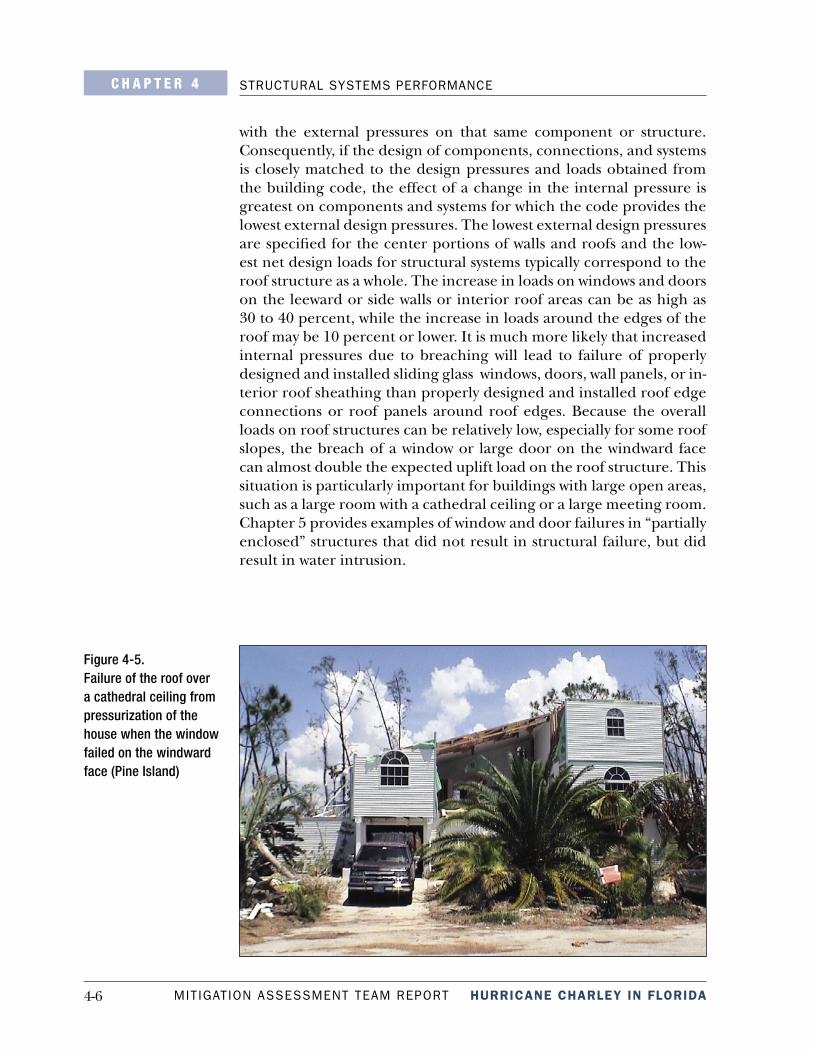
In the areas that experienced code level winds, the MAT observed a number of residences, presumably designed to be “partially enclosed,” with missing garage doors or broken windows (even when those win-dows were large) that survived without structural failure. The successful performance of these buildings seems to attest to the validity of the “partially enclosed” design practice. Figure 4-5 shows an example of a building not designed for internal pressure (not designed according to “partially enclosed” parameters) that resulted in major structural roof failure.
The importance of the internal pressures on the performance or failure of other components and structures can be determined by considering the relative magnitude of the internal pressure effect when compared
4-6 MITIGATION ASSESSMENT TEAM REPORT HURRICANE CHARLEY IN FLORIDA
C H A P T E R 4 STRUCTURAL SYSTEMS PERFORMANCE
with the external pressures on that same component or structure. Consequently, if the design of components, connections, and systems is closely matched to the design pressures and loads obtained from the building code, the effect of a change in the internal pressure is greatest on components and systems for which the code provides the lowest external design pressures. The lowest external design pressures are specified for the center portions of walls and roofs and the low-est net design loads for structural systems typically correspond to the roof structure as a whole. The increase in loads on windows and doors on the leeward or side walls or interior roof areas can be as high as 30 to 40 percent, while the increase in loads around the edges of the roof may be 10 percent or lower. It is much more likely that increased internal pressures due to breaching will lead to failure of properly designed and installed sliding glass windows, doors, wall panels, or in-terior roof sheathing than properly designed and installed roof edge connections or roof panels around roof edges. Because the overall loads on roof structures can be relatively low, especially for some roof slopes, the breach of a window or large door on the windward face can almost double the expected uplift load on the roof structure. This situation is particularly important for buildings with large open areas, such as a large room with a cathedral ceiling or a large meeting room. Chapter 5 provides examples of window and door failures in “partially enclosed” structures that did not result in structural failure, but did result in water intrusion.
Figure 4-5. Failure of the roof over a cathedral ceiling from pressurization of the house when the window failed on the windward face (Pine Island)

4-7HURRICANE CHARLEY IN FLORIDA MITIGATION ASSESSMENT TEAM REPORT
STRUCTURAL SYSTEMS PERFORMANCE C H A P T E R 4
Damage to roof sheathing, though not widespread, was observed (Fig-ure 4-6). This damage was observed by the MAT on older homes most likely designed prior to improvements in the C&C design criteria dis-cussed in Chapter 2.
Figure 4-6. Roof decking failed due to uplift (Deep Creek)
Details in design and construction of wood structures tend to be very vulnerable to the forces associated with high winds even when they are followed carefully from design through construction. Proper structural framing requires a dedicated effort from the designer, to the building official, to the contractor, to ensure that all connections are installed in an approved manner.
In a multi-story building, the framing systems of the floors and the roof act as the diaphragm and transfer forces to the shear wall, which transfers the loads to the foundation. The taller the building, the stronger the shear walls must be to resist lateral wind loads. Over-all, multi-family residential buildings performed well, although older buildings on Pine Island and Captiva Island did sustain considerable damage (Figures 4-7 and 4-8).

4-8 MITIGATION ASSESSMENT TEAM REPORT HURRICANE CHARLEY IN FLORIDA
C H A P T E R 4 STRUCTURAL SYSTEMS PERFORMANCE
Figure 4-7. Multi-family residential building that performed well structurally, although it had severe roof covering and some sheathing failure at the overhangs, allowing water intrusion (Pine Island)
Figure 4-8. Wall failure on older (1980s vintage) multi-family wood-frame building due to lack of load path. Internal pressurization may have also contributed to this failure (Captiva Island).

4-9HURRICANE CHARLEY IN FLORIDA MITIGATION ASSESSMENT TEAM REPORT
STRUCTURAL SYSTEMS PERFORMANCE C H A P T E R 4
4.2 Manufactured Housing
T he pre-1976 HUD standard homes, which are now over 25 years old, performed poorly as expected. These homes were built in accordance with minimum requirements, and many of the
homes were subjected to the narrow path of Hurricane Charley’s highest winds and were damaged beyond repair. Figure 4-9 shows a pre-HUD home that was totally destroyed; however, surrounding pre-HUD homes appeared to have survived with little damage.
Figure 4-9. Pre-1976 HUD manufactured home sustained substantial damage (Bowling Green)
The pre-1994 HUD standard manufactured homes had the benefit of being built in accordance with the HUD standards, but they did not have the additional high-wind resistant features that are found in man-ufactured housing today. Damage to pre-1994 HUD standard homes varied tremendously even for units located near each other in the same park. The levels of damage to units ranged from beyond repair (shown previously in Figure 3-8) to almost intact with only the failure of carports and attachments or screen enclosures.
The post-1994 HUD standard home, built after the improved wind-re-sistant requirements were added to the HUD manufactured housing standards in 1994, performed better than its predecessors. In general, the main wind-force resisting systems in these homes remained intact. In many cases, when an attached accessory structure was torn off a home, it also tore off the metal paneling to which it was attached. Typically, this starts a continuing sequence of peeling of the skin, which could include both walls and the roof (Figure 4-10). The roof structural failures

4-10 MITIGATION ASSESSMENT TEAM REPORT HURRICANE CHARLEY IN FLORIDA
C H A P T E R 4 STRUCTURAL SYSTEMS PERFORMANCE
resulted in significant water intrusion, causing damage to these homes and their contents. Structural failures of accessory structures are dis-cussed in Section 4.6.
Figure 4-10. Post-1994 HUD manufactured home with significant roof damage (peeling of roof panels) resulting from collapse of attached accessory structure (Zolfo Springs).
4.3 Concrete and Masonry Buildings
A mong the most predominant construction materials in the communities impacted by the hurricane are concrete and masonry units (CMUs), which are used for exterior walls. As
shown in Figure 4-11, reinforced concrete masonry structures per-formed well.
Figure 4-11. New concrete masonry residence built to 2001 FBC standards performed well structurally, although it did experience some asphalt shingle damage (Port Charlotte).

4-11HURRICANE CHARLEY IN FLORIDA MITIGATION ASSESSMENT TEAM REPORT
STRUCTURAL SYSTEMS PERFORMANCE C H A P T E R 4
Concrete and masonry construction is commonly used for commer-cial buildings, such as shopping centers and office buildings. These buildings were supported on reinforced concrete foundations with spread or deep foundation systems. Reinforced concrete columns and beams support the superstructures. Exterior load-bearing walls were constructed utilizing CMUs. In general, the floor slabs in multi-story buildings consist of cast-in-place reinforced concrete slabs. At some locations, the floor decks were observed to be supported by open web steel joists with metal deck and concrete topping.
Concrete and reinforced masonry buildings provide a high degree of structural strength, rigidity, and security, and typically provide a long building life span. These buildings have sound structural wall systems due to inherent safety factors and redundancy built into the design and construction. Figure 4-12 illustrates an adequately designed rein-forced masonry wall system.
Figure 4-12. Adequately designed reinforced masonry wall system

4-12 MITIGATION ASSESSMENT TEAM REPORT HURRICANE CHARLEY IN FLORIDA
C H A P T E R 4 STRUCTURAL SYSTEMS PERFORMANCE
In contrast to reinforced masonry, an unreinforced masonry build-ing is very vulnerable to damage in a high-wind event, as shown in Figures 4-13 and 4-14 (and previously in Figure 3-9). The lack of rein-forcing means that uplift is resisted only by the mortar; if the mortar is cracked, the engaging of the dead weight of the walls is reduced in resisting uplift loads. If the roof separates from the walls, the walls become cantilevered and can be blown over.
Figure 4-13. Unreinforced brick wall failure of a building built over 50 years ago (photo taken from the inside of a classroom, looking out) (Punta Gorda)
Figure 4-14. Partial failure of an unreinforced concrete masonry commercial structure (Port Charlotte)

4-13HURRICANE CHARLEY IN FLORIDA MITIGATION ASSESSMENT TEAM REPORT
STRUCTURAL SYSTEMS PERFORMANCE C H A P T E R 4
The roof decking of commercial buildings is generally supported by open web steel joists with metal decking (sometimes with a light-weight concrete topping). Wood trusses are also used for the roof framing. In newer buildings, the roof structure is sometimes anchored to a reinforced bond beam using cast-in-place steel straps. In older unreinforced masonry buildings, the roof structure may be set on the walls with no positive anchorage to the walls or with only minimal an-chorage provided using “J” hooks that effectively anchor the structure only to the top course of masonry.
Fire Station No. 12, a fairly new building in Port Charlotte, is a con-crete structure with reinforced masonry walls and a concrete slab on grade foundation. The building was being used as a shelter for the fire station employees and their families during the hurricane. The roof framing system consisted of wood trusses supported by a tie-beam on the masonry wall. Wood roof trusses over the apparatus bays spanned approximately 68 feet. The anchorage of roof trusses to the load bear-ing wall apparently failed and blew away; however, all other structural components of the building stayed intact (Figure 4-15).
Figure 4-15. Roof truss hurricane anchor straps failed at the tie-beam at Fire Station No. 12 (Port Charlotte)

4-14 MITIGATION ASSESSMENT TEAM REPORT HURRICANE CHARLEY IN FLORIDA
C H A P T E R 4 STRUCTURAL SYSTEMS PERFORMANCE
In comparison, the roof framing system of Fire Station No. 11 in Port Charlotte consisted of open web steel joist with metal decking support-ed by reinforced masonry walls. The main structure of the multi-story concrete frame building stayed intact, and no structural damage was observed to the roof framing system.
4.4 Structural Steel-Frame Buildings
I n structural steel-frame buildings, the main structures of the buildings are supported by structural steel columns bearing on reinforced concrete spread footings or piles. Structural steel
beams and girders support the floors. Shear walls add rigidity to the frames. These buildings are typically constructed using hot-rolled steel sections.
The main structural members of the steel-frame buildings observed by the MAT appeared to have withstood the hurricane force better than the wood and pre-engineered metal structures, but not as well as the reinforced concrete structures. An office building and a shopping center constructed of a structural steel-framing system were observed in Wauchula. The exterior walls and window systems failed, the build-ing envelope was penetrated, and the roof decking blew off the joist; however, no damage was observed to the main structural steel-framing members (Figure 4-16). No heavy steel-frame failures were observed.
Figure 4-16. Older steel-frame structure performed well in spite of major damage to the roof decking and the exterior walls (Wauchula)
4-15HURRICANE CHARLEY IN FLORIDA MITIGATION ASSESSMENT TEAM REPORT
STRUCTURAL SYSTEMS PERFORMANCE C H A P T E R 4
Figure 4-17. Completely destroyed pre-engineered metal building (Arcadia)
4.5 Pre-Engineered Metal Buildings
A pre-engineered metal building system is generally the most economical and is normally utilized for commercial purposes such as warehouses, storage facilities, hangars, and other similar
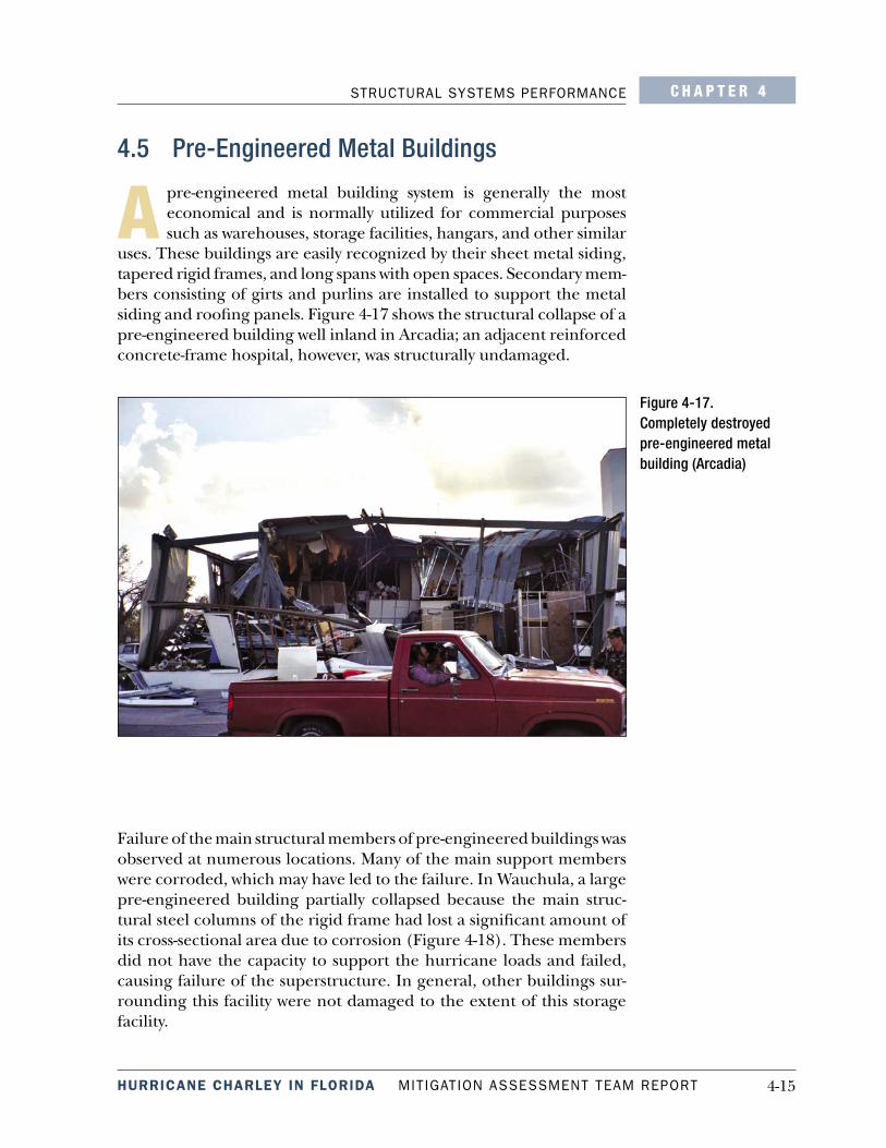
uses. These buildings are easily recognized by their sheet metal siding, tapered rigid frames, and long spans with open spaces. Secondary mem-bers consisting of girts and purlins are installed to support the metal siding and roofing panels. Figure 4-17 shows the structural collapse of a pre-engineered building well inland in Arcadia; an adjacent reinforced concrete-frame hospital, however, was structurally undamaged.
Failure of the main structural members of pre-engineered buildings was observed at numerous locations. Many of the main support members were corroded, which may have led to the failure. In Wauchula, a large pre-engineered building partially collapsed because the main struc-tural steel columns of the rigid frame had lost a significant amount of its cross-sectional area due to corrosion (Figure 4-18). These members did not have the capacity to support the hurricane loads and failed, causing failure of the superstructure. In general, other buildings sur-rounding this facility were not damaged to the extent of this storage facility.

4-16 MITIGATION ASSESSMENT TEAM REPORT HURRICANE CHARLEY IN FLORIDA
C H A P T E R 4 STRUCTURAL SYSTEMS PERFORMANCE
In the Port Charlotte area, some fire stations and other essential fa-cilities were constructed of pre-engineered metal building systems. As previously observed after other storms, in some cases, the pre-engi-neered metal framed systems performed the worst of all the structural framing systems evaluated. Exterior walls consisting of sheet metal siding failed prematurely due to corrosion, resulting in failure of the main structural framing members and column collapse (Figures 4-19 and 4-20).
Figure 4-19. Main column at Fire Station No. 8 collapsed due to corrosion and metal siding failed (Port Charlotte)
Figure 4-18. Collapsed older pre-engineered metal structure (Wauchula)

4-17HURRICANE CHARLEY IN FLORIDA MITIGATION ASSESSMENT TEAM REPORT
STRUCTURAL SYSTEMS PERFORMANCE C H A P T E R 4
4.6 Accessory Structures/Attachments
S ignificant damage to accessory structures was observed by the MAT throughout the path of Hurricane Charley. Most prima-ry buildings had accessory structures (e.g., carports, garages,
tool sheds, laundry and sitting rooms, and screened-in porches/pool enclosures) attached. Some of the accessory structures were free-standing.
Although accessory structures were present on both site-built resi-dences and manufactured homes, almost all of the accessory structures observed by the MAT were associated with manufactured homes. According to the Administrative Code of Florida, all addi-tions are required to be free-standing and self-supporting, with only the flashing attached to the home, unless the added item has been designed to be married to the existing home. Also, additions must be constructed in compliance with the 2001 FBC and locally adopted building codes.
Within the past few years, wind tunnel tests of screen enclosures, open canopy roofs, and roofs over partially enclosed spaces have al-ready led to significant changes in code-based wind load provisions for these structures and additions. Changes in wind loads for screen enclosures that substantially increased the loads on screen walls
Figure 4-20. Significant amount of corrosion at Fire Station No. 8, which contributed to failure shown in Figure 4-19

4-18 MITIGATION ASSESSMENT TEAM REPORT HURRICANE CHARLEY IN FLORIDA
C H A P T E R 4 STRUCTURAL SYSTEMS PERFORMANCE
were adopted in the 2001 FBC, but relatively few of these structures have been designed and built to these newer loads. Observations of newly constructed enclosures from damage assessments support the changes that have been instituted. The majority of the enclosures, attachments, and open canopy roofs were designed for substantially lower loads prior to the 2001 FBC. This likely was the reason for the widespread damage that was observed by the MAT.
In addition, the MAT observed significant damage to not only the acces-sory structures, but also to the homes in general as a result of the poor detailing and performance of the additions. Detailed examples of the types of damage observed are presented in Figures 4-21 through 4-23.
Figure 4-21. Damaged carport (Zolfo Springs)

4-19HURRICANE CHARLEY IN FLORIDA MITIGATION ASSESSMENT TEAM REPORT
STRUCTURAL SYSTEMS PERFORMANCE C H A P T E R 4
Figure 4-22. Damaged garage (Zolfo Springs)
Figure 4-23. Damaged screened porch (Punta Gorda)
In a manufactured home park south of Wauchula where estimated 3-second peak gust winds were in the 100- to 115-mph range, most of the windward- side structures attached to the homes were severely damaged. When the attached structures were blown away from the manufactured home, they typically tore off some material from the main structure at the attachment location, including siding or roofing. This breach in the cladding allowed further damage to the siding or roofing, exposing the home to wind and wind-driven rain. Although none of the manu-factured homes at this location sustained significant structural damage,

4-20 MITIGATION ASSESSMENT TEAM REPORT HURRICANE CHARLEY IN FLORIDA
C H A P T E R 4 STRUCTURAL SYSTEMS PERFORMANCE
many will require substantial repairs because of the damage at the at-tachment site of the accessory structure and resulting water damage.
A primary reason attached aluminum structures failed was inadequate tie-downs of the aluminum posts. The primary failure modes were that the screws attaching the post to the connector broke, the anchors pulled out of the concrete, or the heads of the bolts pulled through the connectors; additionally, sometimes bolts appeared to be corroded to a compromised extent, or the integral washers on some bolt heads had corroded to such an extent that the washers were rendered inef-fective. In most instances, the specific cause of the failure of attached rooms could not be readily determined because the damage was so complete. In addition to having inadequate tie-downs, some of these attached rooms were likely elevated to meet the floor level of the man-ufactured home (approximately 3 feet) and the passage of air beneath may have added to the wind pressure and thereby increased the loads placed on the anchors. Typically, these rooms did not have shear walls capable of resisting wind pressures.
Figure 4-24 shows a freestanding stairway from a manufactured home that was not sufficiently anchored and had blown against the posts of the carport of an adjacent manufactured home, nearly causing the post to be torn from its anchor. If the post had been deflected much more, it is likely that the carport would have been so compromised it would have blown away, resulting in material being torn off the manu-factured home and thereby subjecting it to water intrusion. The pile of debris visible in the distance through the carport is typical of damage caused by attachments in this manufactured home park.
The aluminum screen and pool enclosures that collapsed were ob-served to be on the windward side of residences of site-built and manufactured homes in areas that experienced wind gusts over 110 mph with open exposures to wind (see Figure 4-25). There were sev-eral instances of aluminum debris from the pool enclosures breaking windows of the house to which the enclosures were attached, resulting in interior water damage.
In several cases observed, the apparent cause of the primary failure was that the windward outside corner posts became detached from the slab. Typical construction of these structures included corner posts attached to adjacent 1-inch by 2-inch open back aluminum with only two #10 screws and mid-span posts similarly attached, but with the ad-dition of substantial aluminum angle brackets secured to the slab with substantial anchor bolts. Figures 4-25 through 4-27 show the conse-quences of inadequately attached corner posts. In Figure 4-26, note

4-21HURRICANE CHARLEY IN FLORIDA MITIGATION ASSESSMENT TEAM REPORT
STRUCTURAL SYSTEMS PERFORMANCE C H A P T E R 4
Figure 4-24. Stairway blown into a post of an aluminum carport accessory structure (Zolfo Springs)
that there was no direct tie-down of the corner post to the slab. The corner post was only tied down with lateral screws into one open back. Although the photographs show mid-span post anchoring failures, the MAT observations were that the mid-span posts failed subsequent to the corner posts. An additional mode of failure is likely to have oc-curred as a result of insufficient diagonal bracing.

4-22 MITIGATION ASSESSMENT TEAM REPORT HURRICANE CHARLEY IN FLORIDA
C H A P T E R 4 STRUCTURAL SYSTEMS PERFORMANCE
Figure 4-26. Consequence of corner post not directly tied down to the slab (Punta Gorda Isles)
Figure 4-25. Typical consequence of corner post failure (Punta Gorda Isles)

4-23HURRICANE CHARLEY IN FLORIDA MITIGATION ASSESSMENT TEAM REPORT
STRUCTURAL SYSTEMS PERFORMANCE C H A P T E R 4
Figure 4-27. Breakfast nook window viewed through the pool cage (Punta Gorda Isles)
