femtocells: technology and developments
TRANSCRIPT

Femtocells : Technology and Developments
Wireless Information Theory Summer School, Wireless Information Theory Summer School, Centre for Wireless Communications,
Oulu, 29.7.2011
Jyri Hämäläinen, Comnet/Aalto University
Outline
• Femtocell: Basics
• 3GPP Home (e)NodeB concept– Service requirements for Home Node B (HNB) and Home
eNode B (HeNB)– HeNB and HNB systems: the logical architecture– Home eNode B (HeNB) Radio Frequency (RF)
radio and interference scenarios, and measurements
• Femtocell Networks: Some Research problems
• Some reference material
Femtocell: Basics
Background
• The recent explosive growth of the smartphone market has lead to mass deployment of data-intensive wireless services, e.g., webbrowsing, emailing, streaming of multimedia content.
• Mobile networks are about to reach their capacity limits in terms of the number of supported end-users as well as in terms of the overall data rates. (Thinking exercise: is this claim really true?)
• Increasing the number of macrocell sites is costly and ineffective since around 50 % of voice calls and 70 % of data usage currently takes place indoors (*) where up to 20dB penetration loss(**) reduces the outdoor to indoor signal strength.
(**) Default indoor penetration loss in 3GPP performance evaluation guidelines
(*) G. Mansfield, “Femtocells in the US Market –Busin ess Drivers and Consumer Propositions,” FemtoCells Europe, ATT, London , U.K., June2008. Femto Forum, www.femtoforum.org
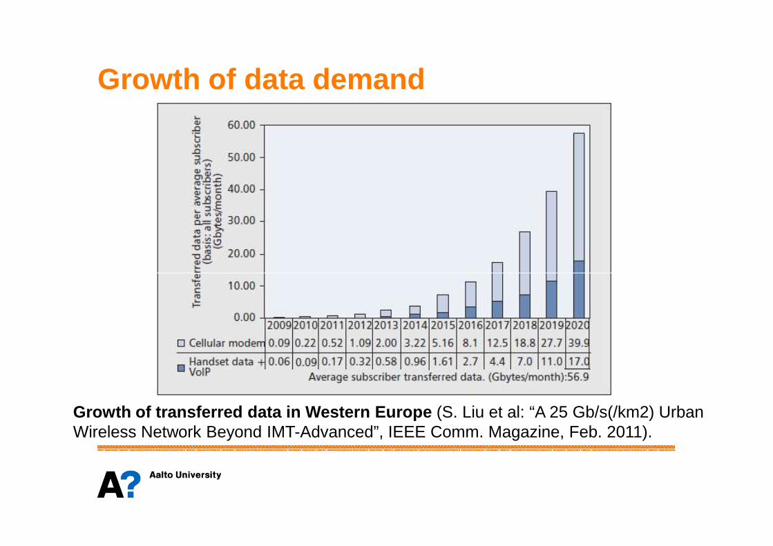
Growth of data demand
Growth of transferred data in Western Europe (S. Liu et al: “A 25 Gb/s(/km2) Urban Wireless Network Beyond IMT-Advanced”, IEEE Comm. Magazine, Feb. 2011).

What is femto base station ?
• In general we can characterize femtocells as follows:
The Femto Base Station is an inexpensive compact base station providing equal radio access interface as a common macrocellularbase station (MBS) towards User Equipments (UEs).
The FBS devices are deployed autonomously by subscribers in residential or enterprise premises in a manner of plug-and play.
The user traffic in FBS is backhauled to the mobile operator core network over IP via the residential broadband wireline connection (DSL, optical network etc.) which is available locally in the site of deployment.

Basic concept
The standardization process of femtocells launched in August 2007 via the 3rd Generation Partnership Project (3G PP) is still under way. First products came to the market at 200 8.

Why femtocells ?
• For the mobile operator:– Data offload from macrocell network
⇒ increased network capacity ⇒Slower growth in macrocell backhaul costs.
– Expanded revenue opportunities (sometimes)– Lower backhaul costs (less macrocell traffic)– Increased customer stickyness (?)– Increased customer stickyness (?)
• For the user:– Better indoor coverage, full speed data transfer at home and
ubiquitous mobility between home cell and overlaying macrocell. – Lower terminal transmission power at home (who cares?)– Extended phone battery life (its short anyway)– One phone number, phonebook & consolidated bill
(not so much of an issue in Finland)

Market pull
• Interestingly, the driving force behind femtocell concept havebeen the operators. – Usually new technologies are pushed by industry that has clear
incentive to sell more HW. (market pull rather than technologypush)
• Actually femtocell concept was initially not attractive to main network manufacturersnetwork manufacturers– Femtocells are low cost high volume products => business
concept is different than in case of macrocell networks.– There was a threat that femtocells could cannibalize operators
main business (macrocellular systems).– Currently femto BS production has been outsourced for
subcontractors.– Big players like NSN and Ericsson carry out the system
integration.
Yet, it is understood that femtocell concept can become an important tool for mobile operators to keep customers satisfied and to lim it the increasing networkcosts. Survival of mobile operators will be crucial also for manufacturers.

3GPP Home (e)NodeB concept

Service requirements for Home Node B (HNB) and Home eNode B (HeNB)
Reference: 3GPP TS 22.220 V10.7.0 (2011-6)
H(e)NB = HNB and HeNB
Access Control requirements
• Subject to operator and H(e)NB Hosting Party agreement, the operator shall be able to configure the H(e)NB with open, hybrid or closed access mode.
• When the H(e)NB is configured for open access mode, it shall be possible for the H(e)NB to provide services to subscribers of any PLMN, subject to roaming agreement.
• When the H(e)NB is configured for hybrid access mode, it • When the H(e)NB is configured for hybrid access mode, it shall be possible for the H(e)NB to provide services to:– its associated CSG members, and– subscribers of any PLMN not belonging to its associated CSG,
subject to roaming agreement.• When the H(e)NB is configured for closed access mode, only
users that belong to its associated CSG shall be able to obtain services.

Closed Subscriber Group (CSG)
• The CSG manager shall be able, under the operator supervision, to add, remove and view CSG membership. NOTE: the interaction of the user with the application that manages the Allowed CSG Lists is out of scope of 3GPP (e.g. Web interface).
• For each subscriber, the network maintains a single CSG list containing the CSG identities that the subscriber is allowed to use.
• The UE shall contain a list of allowed CSG identities (Allowed CSG • The UE shall contain a list of allowed CSG identities (Allowed CSG List). It shall be possible to store the Allowed CSG List in the USIM.
• Each CSG identity shall be associated to a subscriber group which identifies the subscribers allowed to access the CSG.
• When the subscriber group is updated, the affected UE shall be informed accordingly.
Closed Subscriber Group (CSG)
• For temporary members, it shall be possible to limit the period of time during which the subscriber is considered a member of a CSG (granted access rights). It shall be possible to configure a time period for each temporary member.
• The time period shall be configurable by the CSG manager and/or the operator operating the CSG. Unlimited membership to the CSG is allowed.
• In hybrid access mode when services cannot be provided to a CSG • In hybrid access mode when services cannot be provided to a CSG member due to a shortage of H(e)NB resources it shall be possible to continue the established communication of non-CSG members in another cell.
• In hybrid access mode, to minimise the impact on CSG members from established communication of non-CSG members, it shall be possible for the network to allow the data rate of established PS communication of non-CSG members to be reduced.

CSG: source for critical interference ?
Critical interferencebetween femtocellsmay occur since HO is not necessarilypossible in CSG. 2
2b2a
1 1
HNB and HeNB Installation, identification and location requirements• H(e)NB shall have a unique equipment identity.
• It shall be possible to support at least 125 million CSG Identities within a PLMN of an operator.
• The radio transmitter of a H(e)NB shall not be activated until configured and authorised by the operator.
• When installing, provisioning, configuring or re-configuring an • When installing, provisioning, configuring or re-configuring an H(e)NB the operator shall be able to:– Verify the H(e)NB's identity. – Obtain the geographical location of the H(e)NB.(*)
(*) Macrocell level location can be easily found but accura te location is difficultto reach. UE measurement reports can be used to detect ad jacent (e)NB’s.

HNB and HeNB Installation, identification and location requirements• NOTE: The scenario where a H(e)NB is connected to one
operator’s network and later changed to another operator’s network is not required (*).
• The operator shall be able to determine that the H(e)NB is installed and operated in accordance with all relevant regulatory requirements.requirements.
• The operator shall be able to configure the settings of the H(e)NB. In the case where the H(e)NB has detrimental impact on the spectrum usage, the H(e)NB can be set to out-of-service by the operator. (**)
• Installation and activation of a new H(e)NB shall require no reconfiguration of the operators network.
(*) Leads to operator specific H(e)NB products(**) Deciding this will create technical challenge

OA&M Requirements
• H(e)NB shall support the automatic discovery of an operator’s management platform.
• It shall be possible to make use of the operator’s management platform to carry out OA&M functions for H(e)NB. The management connection between H(e)NB and the operator's management platform shall be end-to-end secure.
• H(e)NB shall support OA&M procedures which allow the operator to • H(e)NB shall support OA&M procedures which allow the operator to remotely configure the H(e)NB, deploy software upgrades, detect and report changes in RF conditions and perform general OA&M tasks.(*)
• If the connection between H(e)NB and the rest of the operator network is out of service, then it shall be possible within an operator’s defined time period for the H(e)NB to deactivate the air-interface.
(*) Remote configuration of HeNBs will be a great challen geonce mass deployment of femtocells has taken place
Services support
• Subject to availability of network resources there shall be no difference in the user experience when using the PLMN provided services via H(e)NB or via NodeB/eNodeB (NB/eNB).
• Deployment of H(e)NBs and NB/eNBs on the same spectrum should not degrade the performance of UEs receiving service from NB/eNBs.(*)NB/eNBs.(*)
• Deployment of H(e)NBs and NB/eNBs on the same spectrum should not degrade the NB/eNB’s coverage and capacity. (*)
• H(e)NB shall support emergency calls for both CSG and non CSG members.
• It shall be possible for the operator to provide location information of the UE attempting an emergency call over a H(e)NB.
(*) These requirements set a technical challenge for interworking between femto layer and macro layer

Local IP Access (LIPA)
Mobile operator’s
corenetwork
UE
Local IP traffic
IP traffic to mobile operator’s CN
scope of Local IP access
logical connection for mobile operator IP traffic
Residential/enterpriseIP Network
Local IP Access (LIPA)
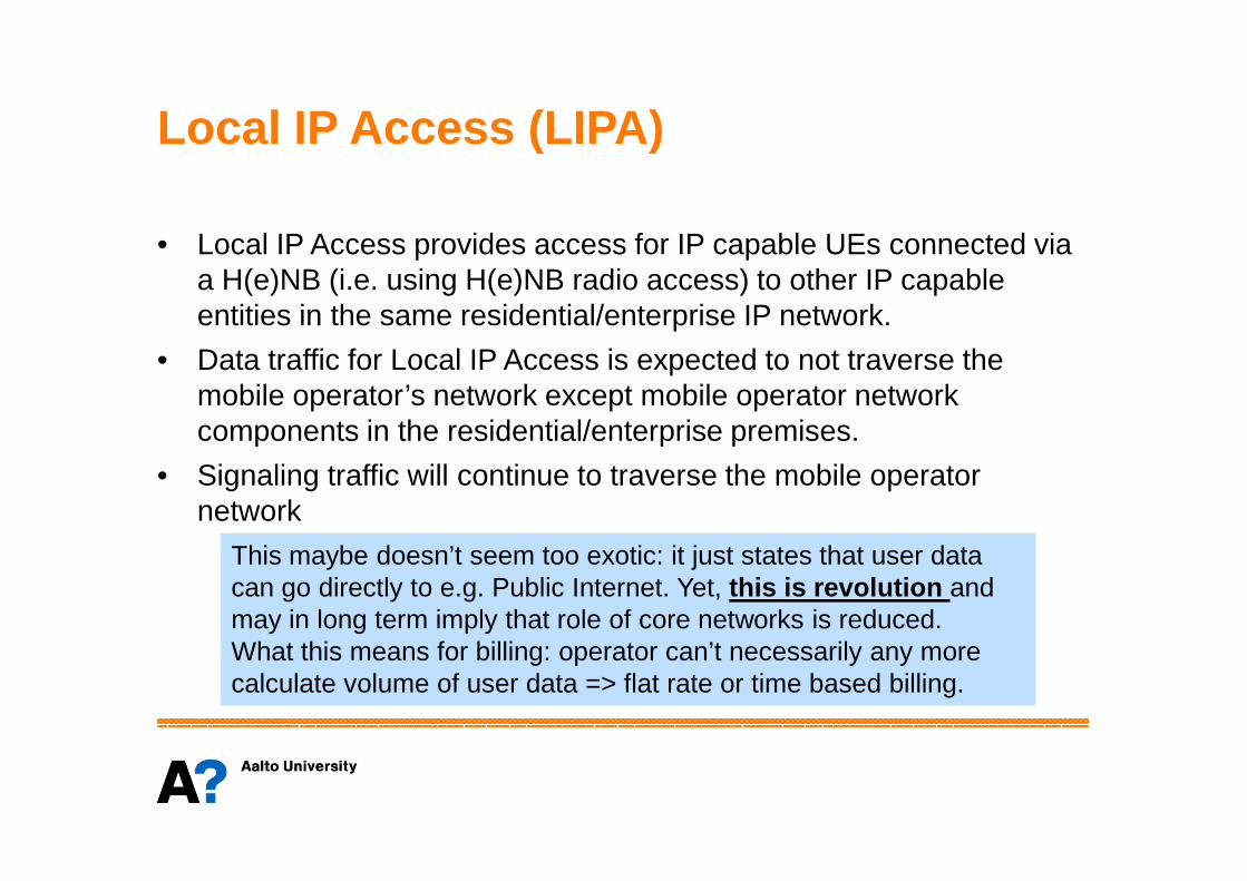
• Local IP Access provides access for IP capable UEs connected via a H(e)NB (i.e. using H(e)NB radio access) to other IP capable entities in the same residential/enterprise IP network.
• Data traffic for Local IP Access is expected to not traverse the mobile operator’s network except mobile operator network components in the residential/enterprise premises. components in the residential/enterprise premises.
• Signaling traffic will continue to traverse the mobile operator network
This maybe doesn’t seem too exotic: it just states that user data can go directly to e.g. Public Internet. Yet, this is revolution and may in long term imply that role of core networks is reduced. What this means for billing: operator can’t necessarily any morecalculate volume of user data => flat rate or time based billing.

Some other requirements
• The H(e)NB may support remote access for a CSG member to the home based network from a UE via a PLMN in order to provide access to IP capable devices connected to the home based network (*).
• It shall be possible to restrict the access to the home based network on per-subscriber basis (e.g. some subscribers may have managed access to their home network and others may not) (**)
• It shall be possible to support Television services (over e.g. MBMS).• It shall be possible to support Television services (over e.g. MBMS).• It shall be possible for the network to set different criteria for access
control in a hybrid cell for CSG and non-CSG members.• The H(e)NB shall provide a high level of security, equivalent or
better than Rel-8 3GPP systems.• Security policy shall be under the control of the H(e)NB network
operator
(*) You can use some devices at home remotely.(**) Your wife may use all devices at home remotely.

Some use cases
H(e)NB Guest UsersUser A and User B are subscribers of Operator 1 and Operator 2 respectively. User A visits User B in his home and User B allows User A to use H(e)NB in User B’s home. User A should be able to access all the services he is subscribed to from Operator 1 based on the policies set by User B and operator 2. Operator 1 and Operator 2 have roaming agreement.
HNB/HeNB – NB/eNB HandoversUser A subcribes to cellular services of Operator 1 and is authorised to access a HNB/HeNB from same or other operator. User A starts service in the H(e)NB coverage and continues moving into a cellular network. Similarly User A starts service in cellular network and continues moving into H(e)NB coverage. User A does not see any impact on services due to mobility in both cases.

Some use casesHybrid access modeIn order to improve the coverage in a shopping mall, H(e)NBs are deployed. The shopping mall owner may have been provided a special deal by the network operator where the employees of the shopping mall will get preferential charging rates and priority access when accessing services via these H(e)NBs. In exchange, the shopping mall owner allows the public to use the H(e)NBs to access the normal network operator services. The H(e)NB Hosting Party should not need to manage the public access and the public should should not need to manage the public access and the public should not need to do anything special in order to get services on the H(e)NB.
Open access modeTypically to enhance coverage or capacity of an operator’s public network, for example in railway stations, airports, stadiums, etc, taking benefit of the H(e)NBs additional functionality (e.g. uncoordinated deployment).
HeNB and HNB systems: the logical architecture
References: 3GPP TR 23.830 V9.0.0 (2009-09; partly outdated) 3GPP TS 25.467 V10.0.0 (2010-12; focus on UTRAN)
H(e)NB = HNB and HeNB
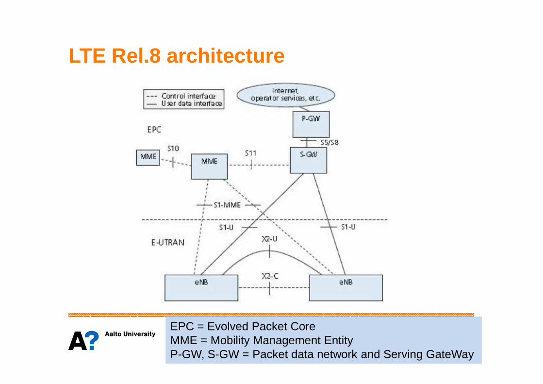
LTE Rel.8 architecture
EPC = Evolved Packet CoreMME = Mobility Management EntityP-GW, S-GW = Packet data network and Serving GateWay

LTE Home eNB architecture

LTE Home eNB architecture
• The HeNB Gateway concentrate a large number of HeNB’sand appears as an MME to the HeNB and the EPC.
• Amongst others it provides the Tracking Area Code (TAC) and network identification (PLMN ID) to the HeNB
• The Security Gateway is a mandatory logical function. It may be implemented either as a separate physical entity or be implemented either as a separate physical entity or integrated into the HeNB-GW. The SeGW secures the communication from/to the HNB.
• HeNB architecture development is ongoing, further information can be found from 3GPP Feature and Study Items list, see– http://www.3gpp.org/ftp/Specs/html-info/FeatureListFrameSet.htm
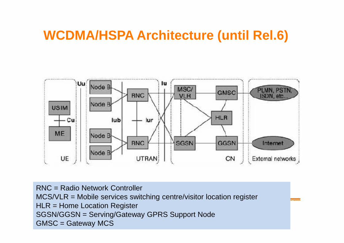
WCDMA/HSPA Architecture (until Rel.6)
RNC = Radio Network ControllerMCS/VLR = Mobile services switching centre/visitor location registerHLR = Home Location RegisterSGSN/GGSN = Serving/Gateway GPRS Support NodeGMSC = Gateway MCS

3G Home NB architecture

3G Home NB architecture
• The HNB-GW appears to the CN as an RNC and serves as a concentrator of HNB connections.
• The Iu interface between the CN and the HNB-GW serves the same purpose as the interface between the CN and a RNC.
• The Local Gateway (L-GW) may be present only when the HNB operates in LIPA mode. When present, it is co-located with the HNB, in which case the HNB has a Gn/S5 interface towards the SGSN/SGW.
• Iuh is the interface between the HNB and HNB GW. For the control • Iuh is the interface between the HNB and HNB GW. For the control plane, Iuh support HNB registration, UE registration and error handling functions. For the user plane, Iuh support user plane transport bearer handling
• The Iurh interface between HNBs admit two options:– Direct interface connectivity between HNBs– HNB-GW serves as a proxy between HNBs
• Gi is the interface towards the residential/IP network (in LIPA mode)
SGW = Serving GateWay

3G Home NB architecture
• The HNB management system (HMS):– facilitates HNB-GW discovery.– provides configuration data to the HNB.– performs location verification of HNB and assigns appropriate
serving elements (HMS, Security Gateway and HNB-GW). • Security Gateway (SeGW):
– terminates secure tunnelling for Iuh, and for Iurh and Gn/S5 for – terminates secure tunnelling for Iuh, and for Iurh and Gn/S5 for certain deployment options.
– authentication of HNB.– provides the HNB with access to the HMS and HNB-GW.
• HNB Gateway (HNB-GW):– terminates Iuh from HNB and appears as an RNC to the Core
network.– supports HNB registration and UE registration over Iuh.
Details of functional split between HNB, HNB-GW and CN

3G Home NB architecture
• From 3GPP TS 25.467 one finds:– Details of functional split between HNB, HNB-GW and CN.– UTRAN functions for HNB access (UE Registration, HNB
Registration, HNB-GW Discovery Function, HNB mobility issues, HNB Configuration Transfer, etc)
• Interestingly, in 3GPP TS 25.467 just three interference mitigation scenarios has been mentioned:mitigation scenarios has been mentioned:– In UL: Adaptively limiting the HNB UE’s maximum UL Tx Power in
connected mode possibly using HNB UE measurement and calculating the path loss between HNB UE and Macro NB.
– In DL: (a) Redirecting unauthorized UE to another carrier possibly based on uplink access attempts by unauthorised UE. (b) Adjusting HNB’s DL CPICH Tx Power adaptively either temporarily or over long term possibly based on uplink access attempts by unauthorised UE.
CPICH = Common Pilot CHannel

Home eNode B (HeNB ) Radio Frequency (RF) radio and interference scenarios, and measurements
References: 3GPP TR 36.921 V10.0.0 (2011-04)3GPP TR 36.922 V10.0.0 (2011-04)3GPP TS 36.104 V10.3.0 (2011-06)3GPP TR 25.967 V10.0.0 (2011-04, omitted here)
H(e)NB = HNB and HeNB

Radio Scenarios : Deploymentconfigurations• Main deployment configurations for Home NodeB:
– Open access or CSG (Closed Subscriber Group)– Dedicated channel or co-channel– Fixed or adaptive (DL) maximum transmit power
• Also fixed or adaptive resource partitioning form a • Also fixed or adaptive resource partitioning form a deployment configuration. – Specifically, the resource partitioning could be performed in
frequency, time or spatial dimensions for interference coordination.
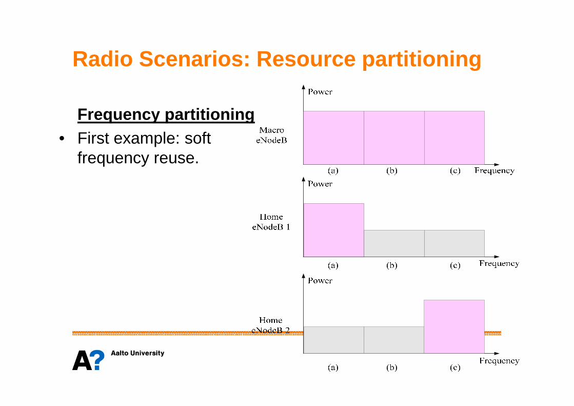
Radio Scenarios : Resource partitioning
Frequency partitioning• First example: soft
frequency reuse.

Radio Scenarios : Resource partitioning
Frequency band for the network
Reuse one
partition
Orthogonal
partition
Frequency partitioning• Second example: partly or fully orthogonal partitioning
partition
Partially overlap
partition
Frequency allocated to macrocell
Frequency allocated to femtocell

Radio Scenarios : Resource partitioning
Frequency partitioning• Third example: Configuration based spectrum partitioning

Radio Scenarios : Resource partitioning
Time partitioningThe resources used in Macro and Home eNBs can also be partitioned and coordinated in the time dimension. Different time zone or UL-DL configurations between HeNBs and macro eNBs or among HeNBsunder specific conditions may provide some flexibility for interference coordination. However, it may also bring new interference risks. Further interference mitigation methods based on the time partitioning needs to be studied.be studied.
Spatial partitioningDue to uplink-downlink channel reciprocity, TDD HeNBs can use beam coordination to improve interference conditions. For example, the HeNB can avoid beam collision with the Macro or other Home eNBs in a proactive or reactive way. These mechanisms may require a certain amount of information exchange between the HeNBs.

Interference ScenariosNumber Aggressor Victim Priority
1 UE attached to Home eNode B Macro eNode B Uplink Yes
2 Home eNode B Macro eNode B Downlink Yes
3 UE attached to Macro eNode B Home eNode B Uplink Yes
4 Macro eNode B Home eNode B Downlink
5 UE attached to Home eNode B Home eNode B Uplink Yes5 UE attached to Home eNode B Home eNode B Uplink Yes
6 Home eNode B Home eNode B Downlink Yes
7 UE attached to Home eNode B and/or Home eNode B
Other System
8 Other System UE attached to Home eNode B and/or Home eNode B

Interference ScenariosDownlink Uplink
RF Aspects : HeNB output power
• From HeNB coverage and capacity point of view, large output power could be attractive.
• However, the maximum output power should be limited in order to control the downlink interference from HeNB towards macrocell layer.
• So, the maximum HeNB output power should be a trade-off between the HeNBperformance and the interference towards close-by macrocell users, which do not have access to the HeNB.
• Based on 3GPP studies the allowed output power of the Home BS is limited to• Based on 3GPP studies the allowed output power of the Home BS is limited to– < + 20 dBm for 1 transmit antenna– < + 17 dBm for 2 transmit antennas– < + 14 dBm for 4 transmit antennas– (< + 11 dBm for 8 transmit antennas, release 10)
• Yet, aim is to use adaptive power setting rather than fixed output power.• In first HNB products the output power will be fixed and in most deployments
between 0dBm and 10dBm.
HeNB measurements and adaptation
• The objectives of the HeNB measurements are– to provide sufficient information to the HeNB for the purpose of
interference mitigation– to provide sufficient information to the HeNB such that the HeNB
coverage can be maintained.
• According to the measurement type, there are two options to collect measurements:collect measurements:– From connected Mode UEs attached to the HeNB– Via a DL Receiver function within the HeNB itself. Such DL receiver
function is also called Network Listen Mode (NLM), Radio Environment Measurement (REM) or "HeNB Sniffer".
• These measurements can also be used during the HeNBself-configuration process
LTE Rel.8 measurements in UE
• RSSI, which is the total received wideband power on a given frequency (from all sources).
• Reference Signal Received Power (RSRP), which for a particular cell is the average of the power measured (and the average between receiver branches) of the resource elements that contain cell-specific reference signals.elements that contain cell-specific reference signals.
• Reference Signal Received Quality (RSRQ) is the ratio of the RSRP and the E-UTRA Carrier Received Signal Strength Indicator (RSSI), for the reference signals.

HeNB System Measurements (1/4): Measurements from all cells
Measurement Type PurposeMeasurement
Source(s)
Received Interference Power
Calculation of UL interference towards HeNB (from MUE)
HeNB UL Receiver
For example, a Received Interference Power measurement value larger than For example, a Received Interference Power measurement value larger than a pre-defined threshold would mean that at least an MUE which is interfered by a HeNB is close to the HeNB and that the MUE's Tx power would cause significant interference towards the HeNB. This measurement value may be used in calculating path loss between the HeNB and the MUE assuming that a single MUE dominates the interference.

HeNB System Measurements (2/4): Measurements to identify surrounding cell layers
Measurement Type PurposeMeasurement
Source(s)
Cell reselection priority information
Distinction between cell types based on frequency layer priority
HeNB DL Receiver
CSG status and IDDistinction between cell layers based on CSG, and self-construction of neighbour list,
HeNB DL Receiver
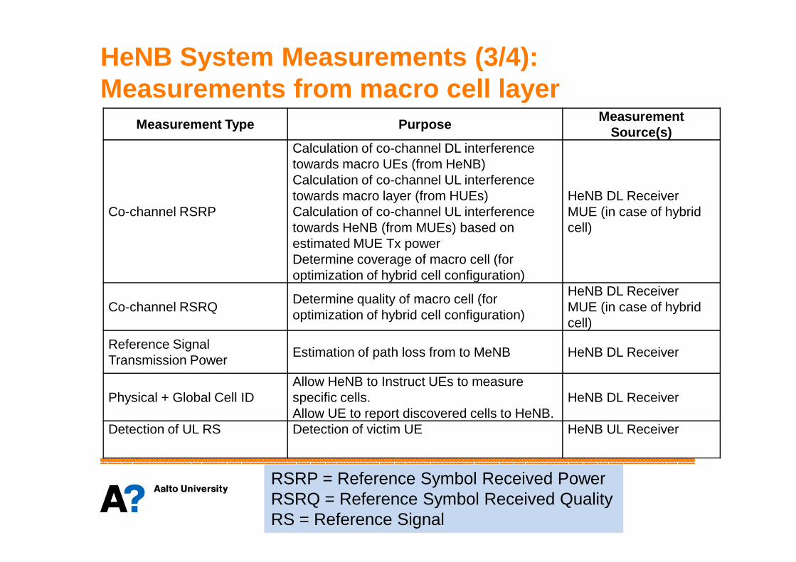
HeNB System Measurements (3/4): Measurements from macro cell layer
Measurement Type PurposeMeasurement
Source(s)
Co-channel RSRP
Calculation of co-channel DL interference towards macro UEs (from HeNB)Calculation of co-channel UL interference towards macro layer (from HUEs)Calculation of co-channel UL interference towards HeNB (from MUEs) based on estimated MUE Tx powerDetermine coverage of macro cell (for optimization of hybrid cell configuration)
HeNB DL ReceiverMUE (in case of hybrid cell)
optimization of hybrid cell configuration)
Co-channel RSRQDetermine quality of macro cell (for optimization of hybrid cell configuration)
HeNB DL ReceiverMUE (in case of hybrid cell)
Reference Signal Transmission Power
Estimation of path loss from to MeNB HeNB DL Receiver
Physical + Global Cell IDAllow HeNB to Instruct UEs to measure specific cells. Allow UE to report discovered cells to HeNB.
HeNB DL Receiver
Detection of UL RS Detection of victim UE HeNB UL Receiver
RSRP = Reference Symbol Received PowerRSRQ = Reference Symbol Received QualityRS = Reference Signal

HeNB System Measurements (4/4 ): Measurements of other HeNB cells
Measurement Type PurposeMeasurement
Source(s)
Co-channel RSRP
Calculation of co-channel DL interference towards neighbour HUEs (from HeNB) Calculation of co-channel UL interference towards neighbour HeNBs (from HUEs)
HeNB DL Receiver
Reference Signal Transmission Power
Estimation of path loss from to HeNB HeNB DL Receiver
Physical + Global Cell ID Allow HeNB to Instruct UEs to measure specific cellsAllow UE to report discovered cells to HeNB.
HeNB DL Receiver

3GPP Interference Control Proposals
• In LTE HeNB system interference control utilize above discussedmeasurements and other information exchanged through network.
• There are different methods proposed for the protection of controlchannels and data channels, see TR 36.921 for details.
• Proposed methods include both– general approaches such as frequency partitioning and power control, and– LTE specific methods
• Example of the latter methods is the control channel interferencemanagement based on fixed time-frequency location of controlinformation:– If adjacent HeNBs apply time and/or frequency shift in DL transmissions =>
not all control channels are overlapping. If data channel transmission is suspended on radio resources that are used for control in adjacent cells, then control channel detection is clearly improved; see next slide.

Control region (36 subcarriers x 1 OFDM symbol)
DL resources available for scheduling (36 subcarriers x 1 OFDM symbol)
Macro-eNB (one unit on x-axis is 1 OFDM symbol ~ 71 us and one
unit on the y-axis is 3 PRBs or 36
subcarriers)
SS
CH
SF-1 SF-2 LegendSF-3
PB
CH
PB
CH
PB
CH
PB
CH
SF-0
PS
CH
PBCH = Physical Broadcast CHannelPSCH, SSCH = Primary and Secondary
Common macro-eNB and HeNB DL bandwidth allocation
SF-2
SS
CH
PS
CH
PB
CH
PB
CH
PB
CH
PB
CH
SF-0 SF-1SF-9
Home-eNB, DL frame timing
offset by k = 16 OFDM symbols
PSCH, SSCH = Primary and SecondarySynchronization Channels.

Femtocell Networks: Some Researchproblems

Some research areas 1/2• Femtocell research classification:
– General level small cell/heterogeneous system research: Aim is usually to find basic principles and new theoretical aspects.
– System specific research: existing specifications form the framework for the research. Aim is usually to proposeenhancements/extensions to existing systems.
• Interference:– Management and avoidance (e.g. scheduling of transmissions,
spectrum usage) spectrum usage) – Suppression (e.g. tranceiver algorithms like beamforming and
advanced receivers)– Interference between macro and femto layers and within femto
layer.• Radio resource management
– Scheduling of resources between macro and femto layers– Static vs dynamic resource allocation. – Load balancing between macrocells and (open access) femtocells

Some research areas 2/2
• Power allocation/calibration for femtocells– How to set TX powers in femtocells?– How to dynamically adjust TX powers in femtocells?
• Self-configuration and optimization– Femtocell networks can be unplanned (user deployed femtocells),
or planned (operator deployed femtocells).or planned (operator deployed femtocells).– Self-configuration and optimization algorithms needed to tune the
network.
• Mobility– Between femtocells and macrocells– Between femtocells– Mobility issues related to femtocells has not been widely
investigated.

Critical interference : A Simple Example
2
Consider DL interference problem of the figure. For the rates there holds:
2
( )( )mmmmm
fffff
BWAR
BWAR
Γ⋅+⋅⋅=
Γ⋅+⋅⋅=
1log
1log
2
2
111 / LP=Γ
(*)
11
2,2,121
222
1,1,212
111
/
/
/
/
fmNm
fmNf
IILPP
LP
IILPP
LP
+++=Γ
+++=Γ
In (*) A and B are constants that can be used to fit rates with some practical systemslike LTE (P. Mogensen, W. Na, I. Z. Kovacs, et al., “LTE capacity compared to the shannon bound,” in Proceedings of the IEEE 65th Vehicular Technology Conference (VTC ’07), pp. 1234–1238, April 2007.
(**)

Critical interference : A Simple Example
• In general there holds:
• Let us consider an illustrative example where we ignore terms If,k
and Im,k related to other femtocell and macrocell interference. Then
2121122211 ,, PPLLLL <<<<<<
fdLPLPLP fW βα 12122122222 / ⋅
⋅⋅=⋅≈=Γ
• We further simplify the model by assuming same fading parameterson femto and macro links (not usuallu true). Then the SINR requirement Gm > Gmin leads to the inequality
md
d
L
L
P
P
L
L
P
P
LPP
LP
m
f
WN
m βαα
22
12
22
12
1
2
22
12
1
2
121
222
/
/
⋅⋅
⋅⋅=⋅≈+
=Γ
2222
/1
12
22
2
1min12 : dad
L
L
P
Pd
W
W
⋅=
⋅⋅Γ>
β
Remark: Dominant interferer model is very relevant in femtocell research. Thereforedistribution of SINR in (*), (**) can be found in many cases and analytical resultscan be deduced.

Critical interference : A Simple Example• Numerical values for illustration:
• Using these values we obtain
( )
=⋅+⋅==−=Γ==
==
==
)43.0)25.12/(11log88.0/(,4,3
indoor UE)(0),outdoor UE(20
indoor UE)(20),outdoor UE(0
10,46
2min
1212
2222
21
WRdB
dBLdBL
dBLdBL
dBmPdBmP
WW
WW
β• Using these values we obtain
• Assume that femtocell is 1km distance from macrocell eNB. • If UE is outside and there is 20dB attenuation towards indoor femtocell,
then macrocell UE should be at least 33.5 meters away from femto eNB.• If macrocell UE is indoors, then 335 meter separation is needed so that
minimum SINR requirement is fulfilled. This is impossible.
)indoors UE(335.0
outdoors) UE(0335.0
==
a
a
Concluding remark: CSG femtocells maycreate local holes on macrocellular coverage.

Interference management approaches(femto -macro layer interference ) • Dedicated frequency carrier for femtocells (not effective and costly
for operators).• Static split of the carrier frequency between macro and femto layers
– Not feasible approach in single carrier systems like HSPA– Brick wall separation of femto and macro spectrum (in e.g. LTE) is easy but
can be ineffective since load in femto layer and macro layer may vary a lotduring the day.
• Dynamic usage of frequency resources: • Dynamic usage of frequency resources: – Separation of femtocell and macrocell transmissions in frequency requires
either active information exchange between macro and femto layers orpredefined rules for spectrum usage. Femtocell backhaul do not supportreal time resource management (i.e. within fast fading coherence time)
• Research question: How to design effective and simple(frequency) resource allocation methods when informationexchange between femto and macro layers is limited, load on layersvary and network topology may change (femtocell switched on and off)? For some solutions and references, see e.g. TR 36.921

Interference management approaches(femto -macro layer interference ) • Multiantenna processing
– Interference suppression by e.g. femto eNB null steering is effective only if channel is directive and accurate channelinformation is available.
– The number of antennas in femto eNBs is expected to be small=> interference suppression can be used to suppress only part=> interference suppression can be used to suppress only partof the interference.
• Femto eNB transmit power allocation/control– Tool for system optimization. – Not necessarily effective approach when solving instantaneous
interference problems.

Example : Dynamic usage of frequencyresources• Femtocell operation frequency can be limited since SNR is usually
high and number of users is small in femtocells.• Macrocell operation frequency cannot be limited since SNR can be
low and number of users maybe large.• LTE example:
– Let us reserve n frequency resource blocks exclusively for macrocell userswhile rest of the band can be used by both femtocells and macriocells.
– Macrocell will schedule to (femtocell) interference free resources users thatare close to femtocells.
– Question: How macrocell know that some of its users heavily suffer fromfemtocell interference?
Exclusive resources for macrocell users
Resources used by bothmacrocell and femtocells

Example : Dynamic usage of frequencyresources
UE measures strength of the received signal fromHeNB and detect its ID
HeNB Broadcasttransmission
UE send measurementresults to Macro eNB
• In LTE macrocell UE can measure the broadcasted reference signalfrom HeNB. Broadcast channels carry also HeNB identity (ID).
• UE then send measurement results to macrocell eNB that knowsHeNB(s) that interfere UE. If there is critical interference, then eNBcan assign exclusive resources for UE.
• In this approach there is a trade-off between user rates on femtocelland macrocell.
transmission results to Macro eNB
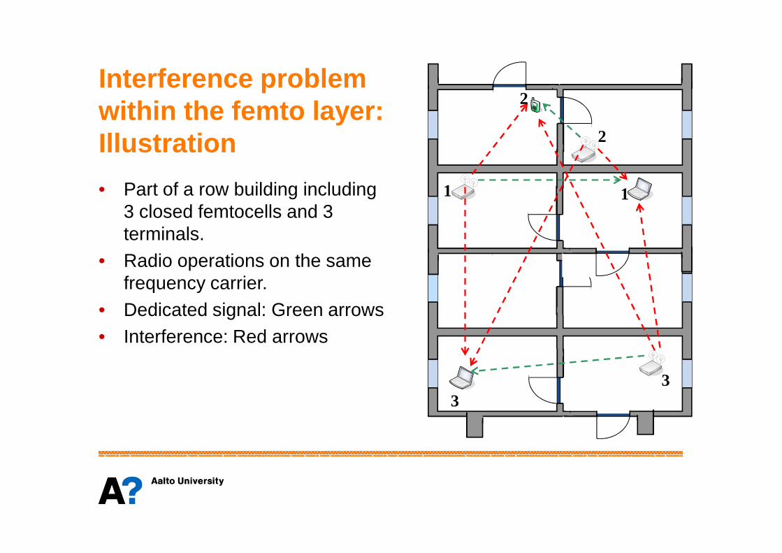
Interference problemwithin the femto layer:Illustration
• Part of a row building including 3 closed femtocells and 3 terminals.
• Radio operations on the same frequency carrier.
1
2
2
1
frequency carrier.• Dedicated signal: Green arrows• Interference: Red arrows
33
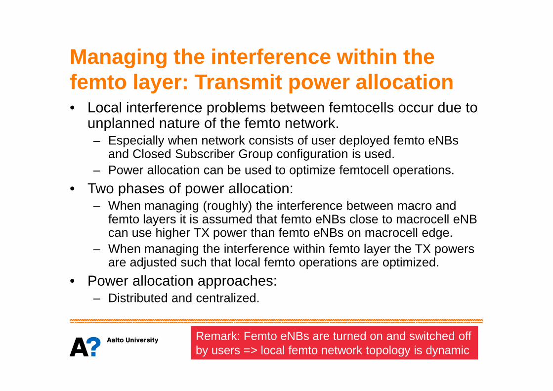
Managing the interference within the femto layer: Transmit power allocation• Local interference problems between femtocells occur due to
unplanned nature of the femto network. – Especially when network consists of user deployed femto eNBs
and Closed Subscriber Group configuration is used.– Power allocation can be used to optimize femtocell operations.
• Two phases of power allocation:• Two phases of power allocation:– When managing (roughly) the interference between macro and
femto layers it is assumed that femto eNBs close to macrocell eNBcan use higher TX power than femto eNBs on macrocell edge.
– When managing the interference within femto layer the TX powersare adjusted such that local femto operations are optimized.
• Power allocation approaches: – Distributed and centralized.
Remark: Femto eNBs are turned on and switched offby users => local femto network topology is dynamic

Distributed vs centralized approach• In (extremely) distributed approach femtocells operate
independently: situation is similar like in WLAN• In (extremely) centralized approach the femto manager have all
channel information and can accurately adjust femto eNB TX powers.
Measurement reports
Cell 1 Femto manager(connected to macro network)
Measurement reports
Cell K
macro network)
All measurementinformation is forwardedto the femto manager.
Practical femto networks are in between the extremes.Different manufacturers may apply different management concepts
Femto manager (or network OA&M) maycreate interference matrices etc
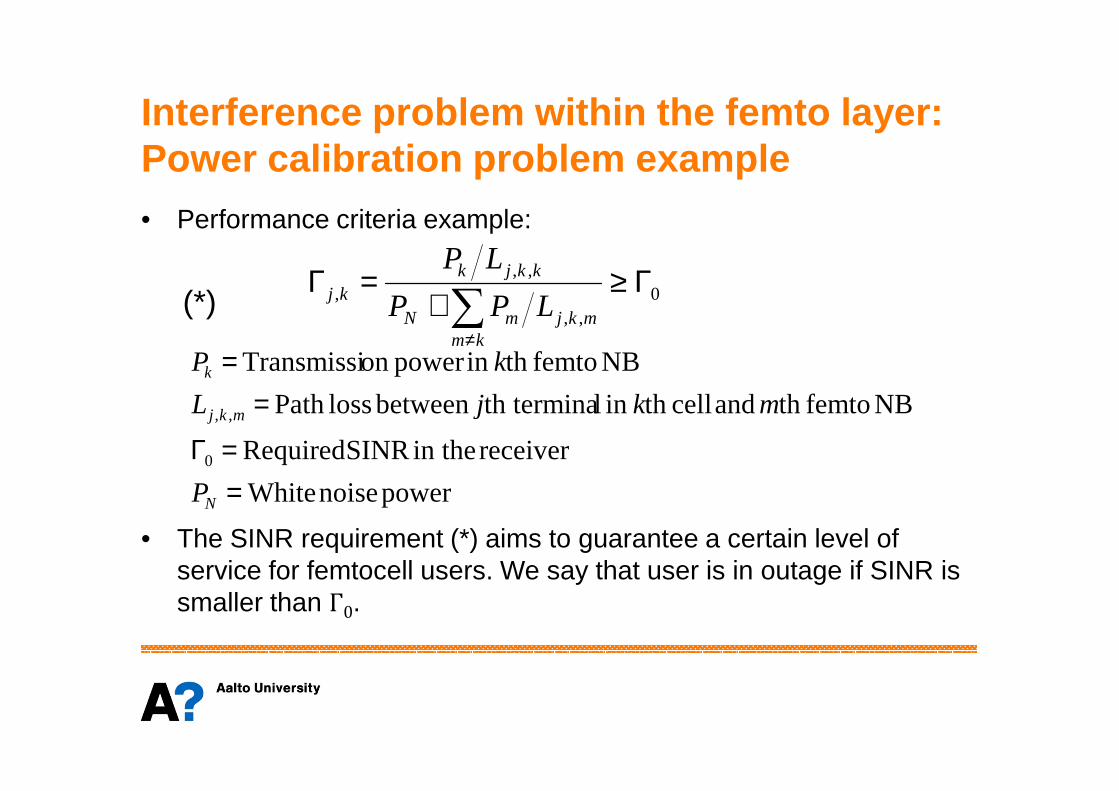
Interference problem within the femto layer: Power calibration problem example• Performance criteria example:
0,,
,,, Γ≥
+=Γ
∑≠km
mkjmN
kkjkkj LPP
LP
NB femtoth and cellth in lth terminabetween lossPath
NB femtoth in power on Transmissi
==k
mkjL
kP
(*)
• The SINR requirement (*) aims to guarantee a certain level of service for femtocell users. We say that user is in outage if SINR is smaller than Γ
0.
power noise White
receiver in the SINR Required
NB femtoth and cellth in lth terminabetween lossPath
0
,,
==Γ
=
N
mkj
P
mkjL

Interference problem within the femto layer: Power calibration problem example• Let Γ
kbe a random variable (SINR in the kth cell). Then, instead of
(1), we may define a statistical performance requirement
where right side defines the probability for outage. This kind of criteria is widely used when mobile system performance is
( ) outk PrPr 0 =Γ<Γ(**)
criteria is widely used when mobile system performance is evaluated.
• Criteria (**) assumes that a certain service level (e.g. in terms of bits/s/Hz) is achieved in kth cell with a given probability.
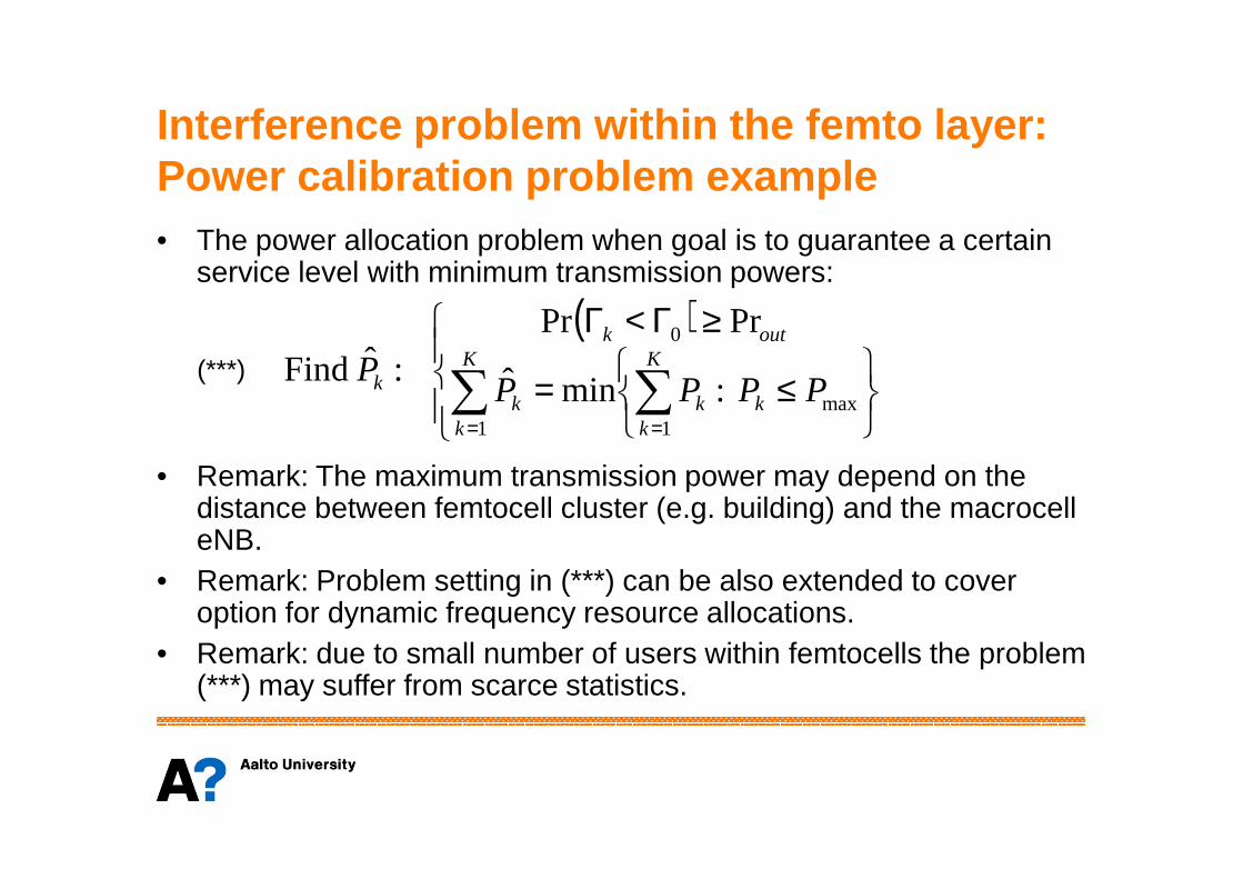
Interference problem within the femto layer: Power calibration problem example• The power allocation problem when goal is to guarantee a certain
service level with minimum transmission powers:
( )
≤=
≥Γ<Γ
∑ ∑= =
K
k
K
kkkk
outk
k PPPPP
1 1max
0
:minˆ
PrPr:ˆ Find(***)
• Remark: The maximum transmission power may depend on the distance between femtocell cluster (e.g. building) and the macrocelleNB.
• Remark: Problem setting in (***) can be also extended to cover option for dynamic frequency resource allocations.
• Remark: due to small number of users within femtocells the problem (***) may suffer from scarce statistics.
k k1 1

Femtocell Networks: The Future
General future developments
• Chipset for femto base stations will become cheaper due to massproduction => at some point femto NB will be an integral part of allDSL boxes (and desk computers too???). – This development takes place only if femtocell concept becomes a
global success.
• Femtocell concept provides a natural playground for various flexible• Femtocell concept provides a natural playground for various flexiblespectrum usage approaches– Example: joint femtocell spectrum for all operators. – Different cognitive radio applications may also become part of femtocell
concept (e.g. spectrum sensing).
• Femto management systems will become more sophisticated. Specifications will provide better means to control femtocelloperations.

One potential aspect: Denseheterogeneous networks
• In addition to femtocellsvarious M2M communication may takeplace on mobile communication spectrum.
• The priorities of differentconnections may vary as connections may vary as well as QoSrequirements.
• This may lead to localheterogeneous systemswhere femtocells need to share the spectrum withM2M communication.

Some reference material

General level publications
• P. Lin et al: ”Macro-femto heterogeneous networkdeployment and management: from business models to technical solutions”, IEEE Wireless Communications, June 2011.
• M. Yavuz et al: ”Interference Management and • M. Yavuz et al: ”Interference Management and Performance Analysis of UMTS/HSPA+ Femtocells”, IEEE Communications Magazine, September 2009.
• V. Chandrasekhar, J. G. Andrews, and A. Gatherer: “Femtocell networks: a survey,” IEEE CommunicationsMagazine, vol. 46, no. 9, pp. 59–67, 2008.

3GPP Home (e)NodeB Concept
• 3GPP TS 22.220 V10.7.0 (2011-6)
• 3GPP TR 23.830 V9.0.0 (2009-09; partly outdated)
• 3GPP TS 25.467 V10.0.0 (2010-12; focus on UTRAN)
• 3GPP TR 36.921 V10.0.0 (2011-04)
• 3GPP TR 36.922 V10.0.0 (2011-04)• 3GPP TR 36.922 V10.0.0 (2011-04)
• 3GPP TS 36.104 V10.3.0 (2011-06)
• 3GPP TR 25.967 V10.0.0 (2011-04)

Some recent technical studies
• O. Simeone, E. Erkip, and S. Shamai Shitz: “Robust Transmission and Interference Management For Femtocells with Unreliable Network Access”, IEEE Journal on Selected Areas in Communications, vol. 28, no. 9, December 2010.
• S. Park, W. Seo, et al: ”Beam Subset Selection Strategy for Interference Reduction in Two-Tier Femtocell Networks”, IEEE Transactions on Wireless Communications, vol. 9, no. 11, November 2010.
• Han-Shin Jo et al: “Self-Optimized Coverage Coordination in FemtocellNetworks”, IEEE Transactions on Wireless Communications, vol. 9, no. 10, October 2010.October 2010.
• M. Husso et al: “InterferenceMitigation by Practical Transmit BeamformingMethods in Closed Femtocells”, EURASIP Journal on Wireless Communications and Networking, Vol. 2010.
• Vikram Chandrasekhar et al: ”Coverage in Multi-Antenna Two-Tier Networks”, IEEE Transactions on Wireless Communications, vol. 8, no. 10, October 2009.
• Vikram Chandrasekhar et al: ”Power Control in Two-Tier Femtocell Networks”, IEEE Transactions on Wireless Communications, vol. 8, no. 8, August 2009.
• Vikram Chandrasekhar et al: “Spectrum Allocation in Tiered Cellular Networks”, IEEE Transactions on Communications, vol. 57 no. 10, October 2009.