femtosecond x rays from laser-plasma accelerators - … · principle of the free-electron ......
TRANSCRIPT

Femtosecond x rays from laser-plasma accelerators
Sebastien Corde, K. Ta Phuoc, Guillaume Lambert, R. Fitour, Victor Malka,
Antoine Rousse, A. Beck, E. Lefebvre
To cite this version:
Sebastien Corde, K. Ta Phuoc, Guillaume Lambert, R. Fitour, Victor Malka, et al.. Femtosec-ond x rays from laser-plasma accelerators. Reviews of Modern Physics, American PhysicalSociety, 2013, 85, pp.85. <10.1103/RevModPhys.85.1>. <hal-01164031>
HAL Id: hal-01164031
https://hal.archives-ouvertes.fr/hal-01164031
Submitted on 16 Jul 2015
HAL is a multi-disciplinary open accessarchive for the deposit and dissemination of sci-entific research documents, whether they are pub-lished or not. The documents may come fromteaching and research institutions in France orabroad, or from public or private research centers.
L’archive ouverte pluridisciplinaire HAL, estdestinee au depot et a la diffusion de documentsscientifiques de niveau recherche, publies ou non,emanant des etablissements d’enseignement et derecherche francais ou etrangers, des laboratoirespublics ou prives.

Femtosecond x rays from laser-plasma accelerators
S. Corde,* K. Ta Phuoc, G. Lambert, R. Fitour, V. Malka, and A. Rousse
Laboratoire d’Optique Appliquee, ENSTA ParisTech, CNRS UMR7639, Ecole Polytechnique,Chemin de la Huniere, 91761 Palaiseau, France
A. Beck and E. Lefebvre
CEA, DAM, DIF, 91297 Arpajon, France
(published 9 January 2013)
Relativistic interaction of short-pulse lasers with underdense plasmas has recently led to the
emergence of a novel generation of femtosecond x-ray sources. Based on radiation from electrons
accelerated in plasma, these sources have the common properties to be compact and to deliver
collimated, incoherent, and femtosecond radiation. In this article, within a unified formalism, the
betatron radiation of trapped and accelerated electrons in the so-called bubble regime, the
synchrotron radiation of laser-accelerated electrons in usual meter-scale undulators, the nonlinear
Thomson scattering from relativistic electrons oscillating in an intense laser field, and the Thomson
backscattered radiation of a laser beam by laser-accelerated electrons are reviewed. The underlying
physics is presented using ideal models, the relevant parameters are defined, and analytical
expressions providing the features of the sources are given. Numerical simulations and a summary
of recent experimental results on the different mechanisms are also presented. Each section ends
with the foreseen development of each scheme. Finally, one of the most promising applications of
laser-plasma accelerators is discussed: the realization of a compact free-electron laser in the x-ray
range of the spectrum. In the conclusion, the relevant parameters characterizing each sources are
summarized. Considering typical laser-plasma interaction parameters obtained with currently
available lasers, examples of the source features are given. The sources are then compared to
each other in order to define their field of applications.
DOI: 10.1103/RevModPhys.85.1 PACS numbers: 52.38.Ph, 52.38.Kd, 52.27.Ny, 41.60.Ap
CONTENTS
I. Introduction 2
II. General Formalism: Radiation from Relativistic Electrons 3
A. Radiation features 3
B. Two regimes of radiation: Undulator and wiggler 4
C. Qualitative analysis of the radiation spectrum 4
D. Duration and divergence of the radiation 6
E. Analytical formulas for the total radiated energy
and the number of emitted photons 6
F. Radiation from an ideal electron bunch 6
G. Radiation reaction 7
H. Real electron bunch: Longitudinal and
transverse emittance 8
III. Electron Acceleration in Plasma 8
A. Ponderomotive force and plasma waves 9
B. The cavitated wakefield or bubble regime 10
C. Experimental production of relativistic electron
bunches 10
IV. Plasma Accelerator and Plasma Undulator: Betatron
Radiation 11
A. Electron orbit in an ion cavity 11
B. Radiation properties 13
1. Without acceleration 14
2. With acceleration 14
C. Numerical results 15
1. Test-particle simulation 15
2. Particle in cell simulation 16
D. Experimental results 18
E. Scalings and perspectives 22
V. Plasma Accelerator and Conventional Undulator:
Synchrotron Radiation 23
A. Electron motion 23
B. Radiation properties 24
C. Numerical results 24
D. Experimental results 25
E. Perspectives 26
VI. Electromagnetic Wave Undulator: Nonlinear Thomson
Scattering and Thomson Backscattering 26
A. Nonlinear Thomson scattering 26
1. Electron orbit in an intense laser pulse 27
2. Radiation properties 28
3. Numerical results 28
4. Experimental results 29
5. Perspectives 30
B. Thomson backscattering 30
1. Electron orbit in a counterpropagating
laser pulse 31
2. Radiation properties 31
3. Numerical results 32
4. Experimental results 33
5. Perspectives 34
VII. Coherent Radiation: Toward a Compact X-Ray
Free-Electron Laser 34
A. The FEL amplifier 35
1. Principle of the free-electron laser process 35*[email protected]
REVIEWS OF MODERN PHYSICS, VOLUME 85, JANUARY–MARCH 2013
10034-6861=2013=85(1)=1(48) � 2013 American Physical Society

2. Required conditions on the electron
beam parameters 37
3. Seeding or self-amplified spontaneous
emission configurations 39
B. Free-electron laser from a laser-plasma accelerator 40
1. With a conventional undulator 40
2. With an electromagnetic wave undulator 41
3. With a plasma undulator 42
VIII. Conclusion 42
Acknowledgments 44
References 44
I. INTRODUCTION
X-ray radiation has been, ever since its discovery overa century ago, one of the most effective tools to explorethe properties of matter for a broad range of scientific re-search. Successive generations of radiation sources have beendeveloped, providing radiation with always higher brightness,shorter wavelength, and shorter pulse duration (Koch, 1983).Despite remarkable progress on x-ray generation methods,there is still a need for light sources delivering femtosecondpulses of bright high-energy x-ray and gamma-ray radiation,emitted from source size of the order of a micron (Service,2002; Pfeifer, Spielmann, and Gerber, 2006). Indeed, theintense activity on the production of such radiation is moti-vated by countless applications in fundamental science,industry, or medicine (Martin et al., 1992; Zewail, 1997;Bloembergen, 1999; Rousse, Rischel, and Gauthier, 2001).For example, in the studies of structural dynamics of matter,the ultimate time scale of the vibrational period of atoms is afew tens of femtoseconds. Fundamental processes such asdissociation, isomerization, phonons, and charge transferevolve at this time scale. High-energy radiation is used toradiograph dense objects that are opaque for low-energyx rays, while micron source size allows one to obtain high-resolution images and makes possible phase contrast imagingto see what is invisible with absorption radiography. Severaltechniques are being developed to produce femtosecondx rays. In the accelerator community, large-scale free-electron laser facilities can now deliver the brightest x-raybeams ever, with unprecedented novel possibilities (Neutzeet al., 2000; Chapman et al., 2006; Brock, 2007; Fritz et al.,2007; Gaffney and Chapman, 2007; Barty et al., 2008;Marchesini et al., 2008). The slicing technique, combininga conventional accelerator with a femtosecond laser to isolateshort electron slices, allows synchrotrons to produce radiationpulses with duration of the order of 100 fs (Schoenlein et al.,2000). High-energy radiation can be delivered by radioactivesources, x-ray tube, and Compton scattering sources based ona conventional accelerator. However, even if widely usedthese high-energy radiation sources have limitations in termsof storage, pulse duration, spectrum tunability, energy range,and source size.
In parallel, alternative and complementary methods basedon laser-produced plasmas have been developed to produceultrashort compact radiation sources covering a wide spectralrange from the extreme ultraviolet (XUV) to the gamma rays.While several laser-based source schemes were proposed
in the early 1970s, this field of research has seen rapid
development when lasers have been able to produce intense
femtosecond pulses (Strickland and Mourou, 1985; Perry
and Mourou, 1994). At laser intensities on the order of
1014 W=cm2, XUV radiation, in the few tens of electronvolts
(eV) energy range, can be produced using the mechanism of
high-order harmonics generation from gas targets (Corkum,
1993; Protopapas, Keitel, and Knight, 1997; Brabec and
Krausz, 2000; Krausz and Ivanov, 2009) or by XUV laser
amplification in a laser-produced plasma (Daido, 2002).
These sources deliver, in most recent configurations, up to a
microjoule of radiation within a beam of a few milliradians
divergence. At laser intensities on the order of 1016 W=cm2,
x-ray sources from laser solid target interaction can produce a
short pulse of K� line emission, emitted within 4� steradians
(Murnane et al., 1991; Kieffer et al., 1993; Rousse et al.,
1994). Discovered more than a decade ago, these sources
have been widely developed and have led to the first structural
dynamics experiments at the femtosecond time scale (Rischel
et al., 1997; Rose-Petruck et al., 1999; Siders et al., 1999;
Cavalleri et al., 2001; Rousse et al., 2001; Sokolowski-
Tinten et al., 2001, 2003). With recent developments, laser
systems can deliver focused intensities above 1018 W=cm2
and the laser-plasma interaction has entered the relativistic
regime (Umstadter, 2003; Mourou, Tajima, and Bulanov,
2006). At this light intensity, relativistic effects become
significant. Electrons can be accelerated within the laser field
or in the wakefield of the laser up to relativistic energies
(Tajima and Dawson, 1979; Joshi et al., 1984; Everett et al.,
1994; Modena et al., 1995; Esarey, Sprangle, Krall, and Ting,
1996; Umstadter et al., 1996; Malka et al., 2002; Patel,
2007; Esarey, Schroeder, and Leemans, 2009). In particular,
laser wakefield acceleration has led to the production
of high-quality femtosecond relativistic electron bunches
(Faure et al., 2004, 2006; Geddes et al., 2004; Mangles
et al., 2004), created and accelerated up to the gigaelectron-
volt level (Leemans et al., 2006; Hafz et al., 2008; Kneip
et al., 2009) within only a few millimeters or centimeters
plasma. Using these relativistic electrons, several novel x-ray
source schemes have been proposed over the past decades to
produce collimated and femtosecond radiation in a spectrum
ranging from the soft x rays to gamma rays. Most of these
schemes are based on the wiggling of relativistic electrons
accelerated in a laser wakefield. In this article, the physics of
these sources is reviewed, and the opportunities offered by
these relativistic electrons to generate ultrashort x-ray radia-
tion (Catravas, Esarey, and Leemans, 2001; Fritzler et al.,
2003; Leemans et al., 2005; Jaroszynski et al., 2006; Gruner
et al., 2007; Hartemann et al., 2007; Malka et al., 2008;
Nakajima, 2008) are highlighted. These sources can deliver
x rays or gamma rays as short as a few femtoseconds, as they
inherit the temporal profile of the laser-plasma electron
bunch, whose few-femtosecond duration was recently experi-
mentally demonstrated (Lundh et al., 2011).The aim of this article is to review the novel x-ray sources
based on relativistic laser and underdense plasma interaction
and to highlight their similitude by using a common formal-
ism for their description. The paper is organized as follows.
In Sec. II, the general formalism of radiation from an accel-
erated relativistic electron is presented, which provides a
2 S. Corde et al.: Femtosecond x rays from laser-plasma accelerators
Rev. Mod. Phys., Vol. 85, No. 1, January–March 2013

framework for the description of the sources discussedthroughout the paper. From this formalism, the relevantparameters describing the properties of the radiation, suchas its spectrum, divergence, number of emitted photons, andduration, can be extracted. As the x-ray sources presentedhere are based on electrons accelerated by laser wakefields[i.e., by the laser wakefield accelerator (LWFA)], a descrip-tion of the most efficient laser-based electron accelerator todate is given in Sec. III.
In Secs. IV, V, and VI, different methods for the pro-duction of incoherent x rays from relativistic electrons arereviewed; the objective is to define the relevant regimes toaccelerate and wiggle electrons in such a way that theyemit x rays. In Sec. IV, betatron radiation is described. Inthat case, a plasma cavity created in the wake of an intenselaser pulse acts as both an electron accelerator and awiggler (referred to as a plasma undulator). The schemepresented in Sec. V relies on the use of laser wakefieldaccelerated electrons, transported and wiggled in a meter-scale periodic arrangement of permanent magnets (conven-tional undulator). This method is the closest to synchrotrontechnology. In Sec. VI, the nonlinear Thomson scatteringand the Thomson backscattering sources are reviewed. Innonlinear Thomson scattering, electrons are directly accel-erated and wiggled in an intense laser field. For theThomson backscattering case, the plasma is used to accel-erate electrons which are then wiggled in a counterpropa-gating electromagnetic wave (EM undulator).
In Sec. VII, an introduction to the topic of the free-electronlaser is given and the conditions for realizing such anultrahigh-brightness and coherent source of radiation withwavelength down to the angstrom (hard x rays) from laser-accelerated electrons are discussed for different types ofundulators (plasma, conventional, and EM).
Other radiation sources based on the laser-plasma interac-tion have been developed and could provide photons in thekeV range. For example, high-order harmonics from gas(Corkum, 1993; Protopapas, Keitel, and Knight, 1997;Brabec and Krausz, 2000; Krausz and Ivanov, 2009) or solidtargets (Tarasevitch et al., 2000; Dromey et al., 2006;Thaury et al., 2007; Teubner and Gibbon, 2009), sourcesbased on the flying mirror concept (Bulanov, Esirkepov, andTajima, 2003; Mourou, Tajima, and Bulanov, 2006; Kandoet al., 2007; Esirkepov et al., 2009), or the K� source(Murnane et al., 1991; Kieffer et al., 1993; Rousse et al.,1994) can produce femtosecond XUV or x-ray radiation.However, they are not based on the same physical principleof acceleration and wiggling of relativistic electrons, and willtherefore not be reviewed here.
II. GENERAL FORMALISM: RADIATION FROM
RELATIVISTIC ELECTRONS
In this section, the radiation from relativistic electrons isintroduced. A qualitative understanding of the phenomenon ishighlighted and analytical results for the relevant generalparameters determining the radiation features are given. Theformalism described here is general and will be common to allthe sources presented throughout the article. We follow theapproach of Jackson (2001) and provide the basic results
necessary for the remainder of the paper. The interested readeris referred to Wiedemann (2007a) for a complete and detaileddescription of synchrotron radiation from bending magnets,undulator, and wiggler insertion devices (e.g., for the angulardistribution of individual undulator harmonics, for polariza-tion or spatial and temporal coherence properties).
A. Radiation features
Relativistic electrons can produce bright x-ray beams iftheir motion is appropriately driven. For all the laser-basedx-ray sources discussed in this article, the radiation mecha-nism is the emission from accelerated relativistic electrons.The features of this relativistically moving charge radiationare directly linked to the electron trajectories. Obtained fromthe Lienard-Wiechert field, the general expression that givesthe radiation emitted by an electron, in the direction ofobservation ~n, as a function of its position, velocity, andacceleration along the trajectory is written (Jackson, 2001)
d2I
d!d�¼ e2
16�3�0c
���������Z þ1
�1ei!½t� ~n�~rðtÞ=c� ~n� ½ð ~n� ~�Þ � _~��
ð1� ~� � ~nÞ2 dt
��������2
:
(1)
This equation represents the energy radiated within a spectralband d! centered on the frequency ! and a solid angle d�centered on the direction of observation ~n. Here ~rðtÞ is the
electron position at time t, ~� is the velocity of the electron
normalized to the speed of light c, and_~� ¼ d ~�=dt is the
usual acceleration divided by c. We stress that this expressionassumes an observer placed at a distance far from the electronso that the unit vector ~n is constant along the trajectory. Theexpression (1) for the radiated energy shows an importantnumber of generic features:
(1) When_~� ¼ 0, no radiation is emitted by the electron.
This means that the acceleration is responsible for theemission of electromagnetic waves from chargedparticles.
(2) According to the term ð1� ~� � ~nÞ�2, the radiated en-
ergy is maximum when ~� � ~n ! 1. This condition is
satisfied when � ’ 1 and ~� k ~n. Thus, a relativisticelectron (� ’ 1) will radiate orders of magnitudehigher than a nonrelativistic electron, and its radiationwill be directed along the direction of its velocity. Thisis simply the consequence of the Lorentz transforma-tion: for an electron emitting an isotropic radiation inits rest frame, the Lorentz transformation implies thatthe radiation is highly collimated in the small cone oftypical opening angle of �� ¼ 1=� around the elec-tron velocity vector, when observed in the laboratoryframe (see Fig. 1). In the following, we considerultrarelativistic electrons, � � 1, and all angles whichwill be defined are supposed to be small so that tan� ’sin� ’ �.
(3) The term ð ~n� ~�Þ � _~� together with the relation_~�k /
~Fk=�3 and_~�? / ~F?=� between applied force and
S. Corde et al.: Femtosecond x rays from laser-plasma accelerators 3
Rev. Mod. Phys., Vol. 85, No. 1, January–March 2013

acceleration (respectively for a force longitudinal or
transverse with respect to the velocity ~�), indicate that
applying a transverse force ~F? ~� is more efficient than
a longitudinal force. The term also shows that the
radiated energy increases with the square of the accel-
eration_~�. More precisely, P / F2
k and P / �2F2?,
where P is the radiated power. Thus, it is much more
efficient to use a transverse force in order to obtain
high radiated energy.(4) The phase term ei!½t� ~n�~rðtÞ=c� can be locally approxi-
mated by ei!ð1��Þt. The integration over time will give
a nonzero result only when the integrand, excluding
the exponential, varies approximately at the same
frequency as the phase term which oscillates at !’ ¼!ð1� �Þ. Given that the velocity ~� of the electron
varies at the frequency!e� , the condition!’ �!e� is
required to have a nonzero result. The electron will
radiate at the higher frequency ! ¼ !e�=ð1� �Þ ’2�2!e� . Thus, the usual Doppler upshift is directly
extracted from this general formula. This indicates the
possibility to produce x-ray beams (!X � 1018 s�1) by
wiggling a relativistic directional electron beam at a
frequency far below the x-ray range: !e� ’ !X=ð2�2Þ.This analysis underlines the directions for the production
of x rays from relativistic electrons: the goal for x-ray gen-
eration from relativistic electrons is to force a relativistic
electron beam to oscillate transversally. This transverse mo-
tion will be responsible for the radiation. This is the principle
of synchrotron facilities, where a periodic static magnetic
field, created by a succession of magnets, is used to induce a
transverse motion to the electrons. The laser-based sources
presented here rely on this principle. In the next sections, the
properties of moving charge radiation in two different re-
gimes are reviewed. The different laser-based x-ray sources
which will be discussed can work in both regimes dependingon the interaction parameters.
B. Two regimes of radiation: Undulator and wiggler
We consider ultrarelativistic electrons with a velocityalong the direction ~ez executing transverse oscillations inthe ~ex direction. Two regimes can be distinguished.
The undulator regime corresponds to the situation wherean electron radiates in the same direction at all times along itsmotion, as shown in Fig. 1. This occurs when the maximalangle of the trajectory c is smaller than the opening angle ofthe radiation cone �� ¼ 1=�. The wiggler regime differsfrom the undulator by the fact that the different sections ofthe trajectory radiate in different directions. Thus, emissionsfrom the different sections are spatially decoupled. Thisoccurs when c � 1=�. The fundamental dimensionless pa-rameter separating these two regimes is K ¼ �c . The radia-tion produced in these two regimes have different qualitativeand quantitative properties in terms of spectrum, divergence,and radiated energy and number of emitted photons.
C. Qualitative analysis of the radiation spectrum
The shape of the radiation spectrum can be determinedusing simple qualitative arguments. In most of the casesdiscussed throughout the article the electron trajectory canbe approximated by a simple transverse sinusoidal oscillationof period �u at a constant velocity � and constant �. The orbitcan be written as
xðzÞ ¼ x0 sinðkuzÞ ¼ c
kusinðkuzÞ ¼ K
�kusinðkuzÞ; (2)
where ku ¼ 2�=�u is the wave-vector norm, x0 is the trans-verse amplitude of motion, and c is the maximum anglebetween the electron velocity and the longitudinal direction~ez. Since the electron energy is constant, an increase of thetransverse velocity leads to a decrease of the longitudinalvelocity. This can be explicitly derived from the assumedtrajectory (2),
�z ’ �
�1� K2
2�2cos2ðkuzÞ
�; (3)
��z ’ �
�1� K2
4�2
�’ 1� 1
2�2
�1þ K2
2
�: (4)
With the trajectory of the electron periodic, the emittedradiation is also periodic since each time the electron is inthe same acceleration state, the radiated amplitude isidentical. The period of the radiated field can be calculatedto obtain the fundamental frequency of the radiation spec-trum. The radiation emitted in the direction ~n, forming anangle � with the ~ez direction, is considered, as represented
in Fig. 2. The field amplitude ~A1 radiated in the direction ~nby the electron at z ¼ 0 and t ¼ 0 propagates at the speed oflight c. At z ¼ �u and t ¼ �u= ��zc, the electron radiates an
amplitude ~A2 ¼ ~A1. The distance separating both ampli-
tudes ( ~A1 and ~A2) corresponds to the spatial period � ofthe radiated field and is given by
FIG. 1 (color online). Illustration of the undulator and wiggler
limits, at the top and the bottom, respectively. The lobes represent
the direction of the instantaneously emitted radiation. c is the
maximum angle between the electron velocity and the propagation
axis ~ez and �� is the opening angle of the radiation cone. When
c � �� (undulator), the electron always radiates in the same
direction along the trajectory, whereas when c � �� (wiggler),
the electron radiates toward different directions in each portion of
the trajectory.
4 S. Corde et al.: Femtosecond x rays from laser-plasma accelerators
Rev. Mod. Phys., Vol. 85, No. 1, January–March 2013

EQ-TARGET ;temp:intralink-;d5;76;544� ¼ �u
��z
� �u cos� ’ �u
2�2
�1þ K2
2þ �2�2
�: (5)
The radiation spectrum consists necessarily in the funda-mental frequency ! ¼ 2�c=� and its harmonics. To knowif harmonics of the fundamental are effectively present inthe spectrum, it is instructive to look at the electron motionin the average rest frame, moving at the velocity ��z in the ~ezdirection with respect to the laboratory frame.
If K � 1, the longitudinal velocity reduction is negligible:
��z ’ � and �z ¼ 1=ffiffiffiffiffiffiffiffiffiffiffiffiffiffiffi1� ��2
z
q’ �. The motion contains only
the fundamental component. Indeed, the motion reduces to asimple dipole in the average rest frame. The spectrum con-sists in a single peak at the fundamental frequency ! whichdepends on the angle of observation �. As K ! 1, radiationalso appears at harmonics.
If K � 1, the longitudinal velocity reduction is significant:
�z ¼ �=ffiffiffiffiffiffiffiffiffiffiffiffiffiffiffiffiffiffi1þ 1
2K2
q. In the average rest frame, the trajectory is
a figure-eight motion. It can contain many harmonics of thefundamental. In the laboratory frame, this can be explainedby the fact that an observer receives short bursts of light ofduration �. Indeed, the instantaneous radiation is contained
within a cone of opening angle �� ¼ 1=� centered on ~� andpoints toward an observer positioned in the direction ~n during
a time �t (see Fig. 3), corresponding to the variation of ~� byan angle �� ¼ 1=�. Locally, a portion of the trajectory canbe approximated by a portion of a circle of radius , such that
the direction of the velocity ~� changes by an angle �� whenthe electron travels a distance de ¼ 2�� ð��=2�Þ ¼ =�,which corresponds to a time �t ¼ te ¼ de=�c. During thetime �t, the radiation has covered a distance d� ¼2 sinð1=2�Þ corresponding to a propagation time of t� ¼d�=c. The radiation burst duration � as observed by an
observer reads
� ¼ te � t� ’ 13
24�3c: (6)
The temporal profile (see the inset of Fig. 3) of the radiationemitted in the wiggler regime has been qualitatively obtained.The Fourier transform of this typical profile gives a preciserepresentation of the radiation spectrum. With the time profilea succession of bursts of duration �, the spectrum will containharmonics up to the critical frequency
!c � 1=�� �3 c
: (7)
Note that the spectrum that arises from a complete calculationof the radiation emitted by a relativistic charged particle ininstantaneously circular motion (Jackson, 2001) is in agree-ment with the above estimation. Such calculation yields thesynchrotron spectrum, which is written in terms of radiatedenergy per unit frequency and per unit time,
dP
d!¼ P�
!c
Sð!=!cÞ; SðxÞ ¼ 9ffiffiffi3
p8�
xZ 1
xK5=3ðÞd;
P� ¼ e2c�4
6��02¼ 2e2!2
c
27��0c�2; !c ¼ 3
2�3 c
; (8)
where we introduced the exact definition of the criticalfrequency !c of the synchrotron spectrum which will beused throughout the review, P� ¼ R
dP=d! is the radiated
power, and K5=3 is the modified Bessel function of the second
kind.The expression for the radius of curvature can be
obtained for an arbitrary trajectory. Its value can be calculatedat each point of the trajectory, corresponding to a particulardirection of observation. In the particular case of a sinusoidaltrajectory, the radius of curvature reads ðzÞ ¼ 0½1þc 2cos2ðkuzÞ�3=2=j sinðkuzÞj and it is minimum when thetransverse position is extremum (x ¼ �x0) and its value atthis point reads
0 ¼ �u
2�c¼ �
�u
2�K; (9)
leading to the following expression for the critical frequency:
!c ¼ 32K�
22�c=�u (10)
¼ 34K!fK�1;�¼0g: (11)
Note that for a nonplanar and nonsinusoidal trajectory, thespectrum extends up to a critical frequency determined by theminimal radius of curvature of the trajectory.
FIG. 3 (color online). In the wiggler limit, the radiation cone
points toward the observer during a time �t, which corresponds
to a duration � for the emitted radiation. This is repeated at each
period: the observer receives bursts of radiation separated by a time
�=c. The inset gives the temporal profile of the radiation power seen
by the observer.
FIG. 2 (color online). Schematic for the calculation of the spatial
period � of the radiation emitted toward the direction of observation
~n, forming an angle � with the ~ez direction. At the two positions
marked by colored points, the electron radiates the same field
amplitude. The distance between these two amplitudes at a given
time corresponds to �.
S. Corde et al.: Femtosecond x rays from laser-plasma accelerators 5
Rev. Mod. Phys., Vol. 85, No. 1, January–March 2013
The parameter K can be considered as the number of de-coupled sections of the trajectory. With each section radiatingtoward a different direction, the radiation is spatially decoupledand leads to bursts of duration � in each direction and to a broadspectrum with harmonics of the fundamental up to !c.
An infinite periodical motion has been considered so far,leading to harmonics that are spectrally infinitely thin. For afinite number of oscillation periods N, Fourier transformproperties imply that the harmonic of number n and ofwavelength �n ¼ �=n has a width given by
��n
�n
¼ 1
nN: (12)
This corresponds to the harmonic bandwidth in a givendirection characterized by the angle �. Since the wavelength�n depends on the angle � [see Eq. (5)], the integration of theradiation over a small aperture of finite dimension broadenseach harmonic. When integrating over the total angular dis-tribution, harmonics overlap and the radiation spectrum be-comes continuous, but keeps the same extension (up to !c).In the undulator limit, in which only the fundamental wave-length is present, the bandwidth is highly degraded whenintegrating over the total angular distribution.
D. Duration and divergence of the radiation
The pulse duration and the divergence of the radiationemitted by a single electron can be deduced from the previousanalysis. If N is the number of periods of the trajectory, theradiation consists in N periods of length � and the totalduration of the pulse is �rjNe¼1
¼ N�=c.
For an undulator, K � 1, the direction of the vector ~�varies along the trajectory by an angle c negligible comparedto �� ¼ 1=�. Hence, the radiation from all sections of thetrajectory overlap and the typical opening angle of the radia-tion is simply �r ¼ 1=�.1 For a wiggler, K � 1, the diver-gence increases in the direction of the transverse oscillation~ex, but remains identical in the orthogonal direction ~ey. In the
direction of the motion ~ex, the typical opening angle of theradiation is �Xr ¼ c ¼ K=�,2 which is greater than �� ¼1=�, while the typical opening angle of the radiation in thedirection ~ey is �Yr ¼ 1=�. For the general case of a transverse
motion occurring in the ~ex and ~ey directions, the angular
profile can take various shapes depending on the exactthree-dimensional (3D) trajectory.
E. Analytical formulas for the total radiated energy and the
number of emitted photons
Analytical calculations provide simple expressions for theradiated energy and the number of emitted photons per
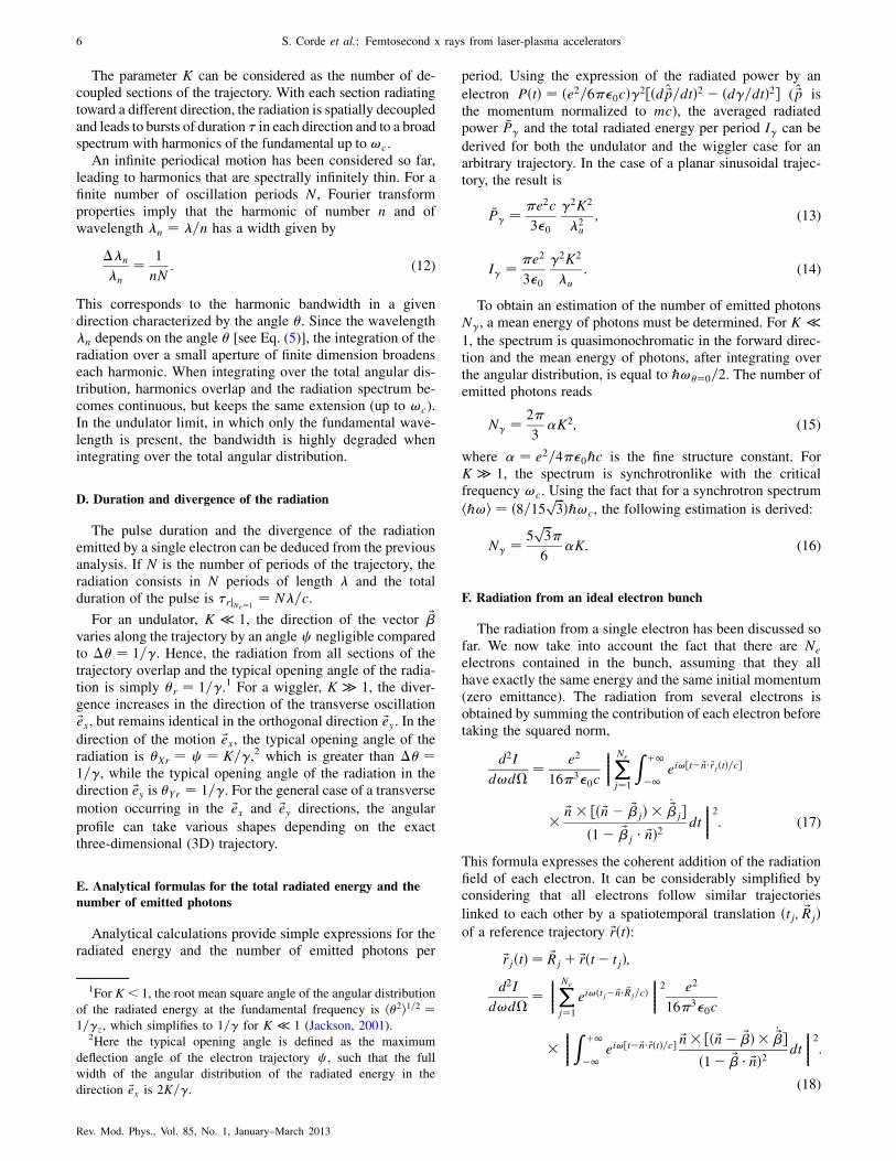
period. Using the expression of the radiated power by an
electron PðtÞ ¼ ðe2=6��0cÞ�2½ðd ~p=dtÞ2 � ðd�=dtÞ2� ( ~p isthe momentum normalized to mc), the averaged radiatedpower �P� and the total radiated energy per period I� can be
derived for both the undulator and the wiggler case for anarbitrary trajectory. In the case of a planar sinusoidal trajec-tory, the result is
�P� ¼ �e2c
3�0
�2K2
�2u
; (13)
I� ¼ �e2
3�0
�2K2
�u
: (14)
To obtain an estimation of the number of emitted photonsN�, a mean energy of photons must be determined. For K �1, the spectrum is quasimonochromatic in the forward direc-tion and the mean energy of photons, after integrating overthe angular distribution, is equal to ℏ!�¼0=2. The number ofemitted photons reads
N� ¼ 2�
3�K2; (15)
where � ¼ e2=4��0ℏc is the fine structure constant. ForK � 1, the spectrum is synchrotronlike with the criticalfrequency !c. Using the fact that for a synchrotron spectrum
hℏ!i ¼ ð8=15 ffiffiffi3
p Þℏ!c, the following estimation is derived:
N� ¼ 5ffiffiffi3
p�
6�K: (16)
F. Radiation from an ideal electron bunch
The radiation from a single electron has been discussed sofar. We now take into account the fact that there are Ne
electrons contained in the bunch, assuming that they allhave exactly the same energy and the same initial momentum(zero emittance). The radiation from several electrons isobtained by summing the contribution of each electron beforetaking the squared norm,
d2I
d!d�¼ e2
16�3�0c
��������XNe
j¼1
Z þ1
�1ei!½t� ~n�~rjðtÞ=c�
� ~n� ½ð ~n� ~�jÞ � _~�j�ð1� ~�j � ~nÞ2
dt
��������2
: (17)
This formula expresses the coherent addition of the radiationfield of each electron. It can be considerably simplified byconsidering that all electrons follow similar trajectories
linked to each other by a spatiotemporal translation ðtj; ~RjÞof a reference trajectory ~rðtÞ:
~rjðtÞ ¼ ~Rj þ ~rðt� tjÞ;d2I
d!d�¼
��������XNe
j¼1
ei!ðtj� ~n� ~Rj=cÞ��������
2 e2
16�3�0c
���������Z þ1
�1ei!½t� ~n�~rðtÞ=c� ~n� ½ð ~n� ~�Þ � _~��
ð1� ~� � ~nÞ2 dt
��������2:
(18)
1For K < 1, the root mean square angle of the angular distribution
of the radiated energy at the fundamental frequency is h�2i1=2 ¼1=�z, which simplifies to 1=� for K � 1 (Jackson, 2001).
2Here the typical opening angle is defined as the maximum
deflection angle of the electron trajectory c , such that the full
width of the angular distribution of the radiated energy in the
direction ~ex is 2K=�.
6 S. Corde et al.: Femtosecond x rays from laser-plasma accelerators
Rev. Mod. Phys., Vol. 85, No. 1, January–March 2013

The radiated energy per unit frequency and unit solid anglefrom an electron bunch is equal to the radiated energy from asingle electron following the trajectory ~rðtÞ multiplied by thecoherence factor
cð!Þ ¼��������XNe
j¼1
ei!ðtj� ~n� ~Rj=cÞ��������
2
: (19)
The value of cð!Þ depends on the electron distribution in the
ðtj; ~RjÞ space. For a uniform distribution, cð!Þ ¼ 0, whereas
for a random distribution, cð!Þ ¼ Ne on average. If thedistribution is microbunched at the wavelength �b ¼2�c=!b, the summation is coherent for the frequency !b
and its harmonics, cðn!bÞ ¼ N2e for n 2 N.
In large accelerators or in laser-plasma accelerators, elec-trons are randomly distributed inside the bunch at the x-raywavelength scale, and the radiation is incoherently summed,
cð!Þ ¼ Ne; (20)
d2I
d!d�jNe
¼ Ne
d2I
d!d�jNe¼1: (21)
The spectrum shape and the radiation divergence �r remainunchanged for an electron bunch. The temporal profile of theradiation is given by the convolution between the electronbunch temporal profile and the radiation profile from a singleelectron. Since the typical electron bunch length is in themicron range, whereas the radiation length from a singleelectron lrjNe¼1
¼ N� is in the nanometer range for x rays,
the duration of the radiation from an electron bunch is in mostcases approximately equal to the bunch duration, �rjNe ¼ �b.
In addition, the electron experiences the radiation fromother electrons in the case of a bunch, which can modify itsmotion and its energy. This interaction of the bunch with itsown radiation can lead to a microbunching of the electrondistribution within the bunch at the fundamental wavelengthof the radiation and its harmonics. This is the free-electronlaser (FEL) process which produces coherent radiation. Herethe coherence factor cðn!bÞ is N2
e instead of Ne, indicatingthat the FEL radiates orders of magnitude higher than con-ventional synchrotrons. However, the FEL effect requiresstringent conditions on the electron beam quality and animportant number N of oscillations. At the present status oflaser-plasma accelerators, realizing a FEL represents a tech-nological challenge. In the following sections, the interactionbetween the electron bunch and its radiation will not be takeninto account because in these schemes the conditions requiredfor the FEL are not fulfilled: the electron distribution remainsrandom along the propagation and the radiation is incoherent.In Sec. VII, the underlying physics of the free-electron laser ispresented in more detail and the possible realization of suchhigh-brightness coherent radiation using laser-plasma accel-erators is discussed.
G. Radiation reaction
The radiation reaction (RR) corresponds to the effect of theelectromagnetic field scattered by an electron on itself, the so-called self-interaction (Landau and Lifshitz, 1994; Jackson,2001; Hartemann, 2002). RR effects can modify the electrontrajectory and its energy and it is therefore important to define
the range of parameters for which these effects come intoplay. The main steps, followed by Dirac to derive the relativisti-cally covariant form of the self-force associated with RR, are tosolve for the self-quadripotential As
� scattered by the electron in
terms of Green’s functions, and then to calculate the associatedelectromagnetic force on the electron, Fs
� ¼ �eð@�As� �
@�As�Þu�, where u� ¼ dx�=d� is the electron quadrivelocity
with � the electron proper time. This leads to the Dirac-Lorentzequation of motion for a pointlike electron,
dp�
d�¼ �eF��u
� þ �0
�d2p�
d�2� p�
m2c2
�dp�
d�
dp�
d�
��;
(22)
where the first term is the Lorentz force with F�� the external
electromagnetic field tensor, the last two terms that definethe RR self-force correspond, respectively, to the Schottterm and the radiation damping term, p� ¼ mu� is the
electron quadrimomentum, and �0¼2re=3c¼e2=6��0mc3¼6:26�10�24 s, with re the classical electron radius. The Schottterm �0d
2�p� ¼ �d�G� accounts for the change of energy
momentum G� of the external field, while the radiation
damping term ��0p�ðd�p�d�p�Þ=m2c2 ¼ �d�H� accounts
for the change of energy-momentum H� of the scattered
electromagnetic wave (Hartemann, 2002).Several difficulties appear in the point electron model
described by the Dirac-Lorentz equation (22). First, it admitsunphysical runaway solutions with exponentially increasingacceleration, which can be eliminated by requiring the Dirac-Rohrlich asymptotic condition lim�!�1d�p� ¼ 0. Second,
physical solutions present acausal preacceleration, i.e., thatelectron momentum changes before an external force issuddenly applied, on a time scale �0. Equation (22) can beapproximated by evaluating the RR self-force with the solu-tion of the zeroth-order equation d�p� ¼ �eF��u
� (Landau
and Lifshitz, 1994). This yields the Landau-Lifshitz equationwhich neither admits runaway solutions nor presents acausalpreacceleration behavior.
For the case of an electron undulating according to Eq. (2),it is important to define the range of parameters for whichradiation the reaction comes into play and has to be includedin the description of the electron motion and its radiation. Forrelativistic electrons, the dominant term in the radiationreaction comes from the energy momentum transferred tothe scattered electromagnetic wave [while for rest electrons,the radiation reaction describes the direct exchange of energymomentum between the external field and the scattered wave(Hartemann, 2002)]. The rate of energy loss �� for the
electron can be estimated from mc2d�=dt ¼ � �P�, with �P�
the average power radiated by the electron given by Eq. (13).It leads to �ðtÞ ¼ �0=ð1þ ��tÞ with
�� ¼ �02�0K
2
�2�c
�u
�2; (23)
and �0 is initial gamma factor of the electron (Telnov, 1997;Huang and Ruth, 1998; Esarey, 2000; Koga, Esirkepov,and Bulanov, 2005; Michel et al., 2006). Therefore, theradiation reaction can be neglected when the interactionduration or equivalently the number of oscillations satisfyrespectively, � � ��1
� and N � NRR ¼ �u=ð2�2c�0�0K2Þ.
S. Corde et al.: Femtosecond x rays from laser-plasma accelerators 7
Rev. Mod. Phys., Vol. 85, No. 1, January–March 2013

With conventional undulators (see Sec. V), RR will always benegligible; for �10 GeV electrons, �u � 1 cm and K � 1,the limiting number of period NRR is on the order of 1:3�107. For current and short-term laser-based betatron experi-ments (see Sec. IV), RR is negligible but in the long term or forelectron beam driven plasma accelerators [e.g., parameters of
the Facility for Advanced Accelerator Experimental Tests(FACET) (Hogan et al., 2010)], �10 GeV electrons, �u �1 cm, and K � 100 lead to NRR � 1:3� 103. For Thomson
backscattering (see Sec. VI), GeV electrons colliding with alaser pulse of strength parameter K � 10 and wavelength � ¼0:8 �m (�u ¼ �=2) leads toNRR � 60. The radiation reactioncan be neglected in Thomson backscattering for sub-GeVelectron beams and the laser pulse of strength parameter onthe order of unity, for which NRR * 6� 103.
In the realm of quantum electrodynamics (QED), theradiation reaction corresponds to the recoil experienced by
an electron due to consecutive incoherent photon emissions(Di Piazza, Hatsagortsyan, and Keitel, 2010). Quantumeffects become important when the electron energy lossassociated with the emission of a photon is on the order of
the electron energy. Signatures of quantum effects can beobserved before entering this quantum regime. Indeed, quan-tum fluctuations, which imply that different electrons emit a
different number of photons (that carry different energies)and hence lose a different amount of energy, can lead to anobservable increase of the electron beam energy spread(Esarey, 2000). Experimentally, a study of the quantum re-
gime is accessible in the framework of Compton scattering(see Sec. VI). QED effects, such as nonlinear Comptonscattering (Bula et al., 1996) and the production of
electron-positron pairs from light (Burke et al., 1997),were observed in the SLAC E-144 experiment, where46.6 GeV electron beams collided with relativistic laserpulses with intensities of 1018 W cm�2.
H. Real electron bunch: Longitudinal and transverse emittance
In the previous section, ideal bunches with electrons at thesame energy and same momentum have been considered inorder to simply discuss the effect of summation of the
radiation from each electron. However, in realistic bunches,electrons have slightly different energies and momenta. Moreprecisely, inside the bunch, electrons that are at the samelocation can have different energies and momenta. This
implies, for example, that the bunch cannot be focused andcompressed on an infinitely small point. This limitation isfundamental and inherent to the bunch; it does not depend on
practical realization. The parameter which accounts for that iscalled the emittance and is related to the volume occupied bythe electrons in the 6D phase space (x, y, z, px, py, and pz) at
a given time (Humphries, 1990). The 6D phase volume isconstant in time if only smooth external forces are applied
and if collisions are neglected (the phase volume conservationis a consequence of the collisionless Boltzmann equation).The emittance reflects the quality of the electron beam be-cause it quantitatively indicates if electrons have the same
coordinates, direction, and energy.For a relativistic electron beam traveling in the ~ez direc-
tion, an emittance is defined for each dimension: the z one is
called longitudinal and two others are transverse (x and y).For a uniform distribution with sharp boundary, the normal-ized emittance �aN is defined as the area occupied by elec-trons in the ða; pa=mcÞ space divided by � (a ¼ x, y, and z).But because realistic electron beams have diffuse boundaries,the normalized root-mean-square (rms) emittance is used anddefined as
�aN ¼ffiffiffiffiffiffiffiffiffiffiffiffiffiffiffiffiffiffiffiffiffiffiffiffiffiffiffiffiffiffiffiffiffiffiffiffiffiffiffiffiffiffiffiffiffiffiffiffiffiffiffiffih�a2ih�p2
ai � h�a�pai2q
=mc; (24)
with a ¼ x; y; z and where �a ¼ a� hai, �pa ¼ pa � hpai.For transverse dimensions, it is convenient to use the unnor-malized emittance �a, which is related to the area occupied byelectrons in the ða; a0Þ trace space (a ¼ x; y), where a0 ’pa=pz is the transverse angle with respect to the propagationaxis z,
�a ¼ffiffiffiffiffiffiffiffiffiffiffiffiffiffiffiffiffiffiffiffiffiffiffiffiffiffiffiffiffiffiffiffiffiffiffiffiffiffiffiffiffiffiffiffiffiffiffiffiffiffiffiffih�a2ih�a02i � h�a�a0i2
q; a ¼ x; y: (25)
It is generally expressed in �mmmrad. For cylindricallysymmetric beams, the emittance �r (defined in the same wayby putting a ¼ r) can be used. The normalized emittance isrelated to the unnormalized one by �N ¼ ��� and has theadvantage of being conserved during acceleration (in systemswhich preserve the emittance). In a focal plane, where there isno correlation between position and angle, the emittance issimply the product of the rms transverse size a by the rmsangular dispersion a0 ,
�a ¼ a a0 ; a ¼ x; y; r: (26)
For incoherent radiation of electrons oscillating in undu-lator or wiggler devices, the emittance and energy spreadhave the following effects. The electron beam is focused inthe device, with a transverse size and a divergence �satisfying � ¼ �. Because of the angular spread, the radia-tion angular distributions from each single electron are slightlyshifted from one another, leading to a redshifted broadening ofharmonic bandwidths [an electron with direction � with re-spect to the propagation axis contributes on axis with higherwavelength � ¼ ��¼0ð1þ �2
z�2Þ; see Eq. (5)]. The energy
spread effect is straightforward: electrons with different ener-gies radiate at slightly different wavelengths, leading to abroadening of harmonic bandwidths. These effects resultin a modified bandwidth given by ð��n=�nÞ2 ¼ ð1=nNÞ2 þð2��=�Þ2 þ ð�2
z�2= 2Þ2. Hence, the bandwidth of an har-
monic at a given direction comes from three different effects:the finite number of periods, the energy spread, and the angularspread (which depends on the emittance).
The transverse emittance is essential for transport consid-erations and applications such as the free-electron laser.Concerning the FEL application, required conditions on thetransverse emittance and the energy spread will be given inSec. VII. A smaller transverse emittance permits one to trans-port or focus the electron beam on a smaller focal spot size.
III. ELECTRON ACCELERATION IN PLASMA
The possibility to accelerate electrons in laser-producedplasmas was originally proposed by Tajima and Dawson(1979). They suggested to use the intense electric field of arelativistic plasma wave, created in the wake of an intenselaser pulse, to accelerate electrons to relativistic energies. Themain advantage of plasmas relies on their ability to sustain an
8 S. Corde et al.: Femtosecond x rays from laser-plasma accelerators
Rev. Mod. Phys., Vol. 85, No. 1, January–March 2013

accelerating gradient much larger (on the order of 100 GeV/
m) than a conventional radio frequency accelerating module
(on the order of 10 MeV/m). This means that electrons could
be accelerated up to 1 GeV in millimeter- or centimeter-scale
plasmas (Leemans et al., 2006; Hafz et al., 2008; Froula
et al., 2009; Kneip et al., 2009; Clayton et al., 2010) while a
few tens of meters would be necessary to reach the same
energy in conventional accelerators.This acceleration method has experienced a remarkable
development over the past decades, mainly thanks to the
advent of high-intensity lasers and to a better understanding
of the physical mechanisms driving the acceleration.
Different plasma accelerator schemes have been developed
over the years,3 leading to electron bunches with ever-
increasing quality. The most efficient to date is the so-called
bubble, blowout, or cavitated wakefield regime (Pukhov and
Meyer-ter Vehn, 2002; Pukhov, Gordienko et al., 2004; Lu,
Huang, Zhou, Mori, and Katsouleas, 2006; Lu, Huang, Zhou,
Tzoufras et al., 2006; Lu et al., 2007). In that regime,
depending on the chosen parameters, electron bunches can
now be produced with tunable energy in the hundreds of MeV
range (Faure et al., 2006), low divergence (mrad), a relatively
high charge (� 100 pC), and a bunch duration of less than
10 fs (Faure et al., 2004; Geddes et al., 2004; Mangles et al.,
2004, 2006; Tsung et al., 2004, 2006; van Tilborg et al.,
2006; Glinec et al., 2007; Thomas et al., 2007; Davoine
et al., 2008; Lundh et al., 2011). Because the x-ray sources
which will be reviewed are based on laser-plasma accelerators,
this section is dedicated to a short description of wakefield
acceleration in the cavitated regime. In particular two impor-
tant physical mechanisms are introduced: the ponderomotive
force and the plasma wave. After a brief description of the
characteristics of the acceleration mechanism, recent experi-
mental progress is presented. We refer the interested reader to
the recent article of Esarey, Schroeder, andLeemans (2009) for
a complete review of laser-plasma electron accelerators.
A. Ponderomotive force and plasma waves
The ponderomotive force is a force associated with the
intensity gradients in the laser pulse that pushes both elec-
trons and ions out of the high-intensity regions. Ions, being
much heavier than electrons, still remain for short interaction
times whereas electrons are cast away. This leads, in an
underdense plasma, to the formation of a relativistic plasma
wave whose fields can accelerate electrons. Here a short
description of the ponderomotive force and of the excitation
of a plasma wave (Kruer, 1988) is given.
Because of the mass of the plasma ions, they can beconsidered motionless for short interaction times.Considering a fluid description for the plasma electrons, theequation of motion for a fluid element submitted to theelectromagnetic force reads4
@ ~p
@t¼ @ ~a
@tþ c ~rð�� �Þ; (27)
where ~p ¼ ~p=mc is the normalized momentum of an electronfluid element, � is the relativistic factor of an electron fluid
element, and � ¼ eV=mc2 and ~a ¼ e ~A=mc are, respectively,the normalized scalar potential and the normalized vectorpotential of the electromagnetic fields. ~a describes the high-
frequency laser pulse, c ~r� is the Coulomb force associated
with the charge distribution, and �c ~r� is the relativisticponderomotive force which expels electrons away from thelaser pulse. In the absence of Coulomb and ponderomotive
forces, the equation simplifies to ~p ¼ ~a, corresponding to thefast electron oscillation in the laser pulse. Depending on theamplitude of the laser pulse normalized vector potential a0,plasma electrons oscillate with relativistic velocities j ~vj ’c ða0 > 1Þ or with velocities much smaller than c (a0 � 1).An inhomogenous laser intensity distribution leads to aninhomogenous � distribution and to a ponderomotive forcethat pushes plasma electrons from the high � region (corre-sponding to high a0) to the low � region (low a0). This slowdrift motion of the plasma electrons leads to a charge density
distribution responsible for a Coulomb force c ~r� (byvirtue of the Poisson equation 4� ¼ =�0).
On the other hand, a small charge density perturbation in aplasma oscillates at a characteristic frequency, the plasma
frequency!p ¼ ffiffiffiffiffiffiffiffiffiffiffiffiffiffiffiffiffiffiffiffiffinee
2=m�0p
, where ne is the electron density
of the plasma. For example, if we translate an electron slice(continuously, without crossing between different electrons)from its initial position, the slice will oscillate around itsinitial position at the plasma frequency because of the restor-ing Coulomb force from the plasma ions. These plasmaoscillations, called plasma waves, are excited by the pon-deromotive force of the laser pulse, which creates the initialcharge density perturbation. The phase velocity of the plasmawave v�, excited in the wake of the laser pulse, is approxi-
mately equal to the laser group velocity.For a low-intensity laser pulse, with a normalized vector
potential amplitude a0 � 1, the excited plasma wave is linearand has a sinusoidal shape at the plasma frequency, �ð~r; tÞ ¼�0ð~rÞ sinð!ptÞ. For a higher intensity, a0 > 1, the plasma
wave becomes highly nonlinear and can involve transversecurrents and a quasistatic magnetic field (Gorbunov, Mora,and Antonsen, 1996).
Relativistic plasma waves can be produced in variousregimes depending on the laser and plasma parameters. Forappropriately chosen parameters, electrons can be trapped ata proper phase of the plasma wave and experience its fieldover a distance sufficiently long to be accelerated up torelativistic energies.
3For an overview of the historical development of the field, see
Tajima and Dawson (1979), Joshi et al. (1984), Kitagawa et al.
(1992), Clayton et al. (1993), Everett et al. (1994), Amiranoff
et al. (1995), (1998), Coverdale et al. (1995), Modena et al. (1995),
Nakajima et al. (1995), Esarey, Sprangle et al. (1996), Umstadter
et al. (1996), Moore et al. (1997), Ting et al. (1997), Wagner et al.
(1997), Gordon et al. (1998), Gahn et al. (1999), Santala et al.
(2001), Leemans et al. (2002), Malka et al. (2002), Najmudin
et al. (2003), Pukhov (2003), Bingham, Mendonca, and Shukla
(2004), Mangles et al. (2005), Joshi (2007), Patel (2007), and
Esarey, Schroeder, and Leemans (2009).
4Equation (27) assumes that ~r� ð ~p� ~aÞ is initially zero, which
is the case in practice because both ~p and ~a are zero before the
passage of the laser pulse in the plasma.
S. Corde et al.: Femtosecond x rays from laser-plasma accelerators 9
Rev. Mod. Phys., Vol. 85, No. 1, January–March 2013

In practical units, the plasma wavelength �p ¼ 2�c=!p
and the laser strength parameter a0 are given by
�p ½�m� ¼ 3:34� 1010=ffiffiffiffiffiffiffiffiffiffiffiffiffiffiffiffiffiffiffiffiffiffine ½cm�3�
q; (28)
a0 ¼ 0:855ffiffiffiffiffiffiffiffiffiffiffiffiffiffiffiffiffiffiffiffiffiffiffiffiffiffiffiffiffiffiffiffiffiffiffiffiffiffiffiffiffiffiffiffiffiffiffiffiffiI½1018 W=cm2��2
L½�m�q
; (29)
where I is the laser intensity and �L is the laser wavelength.
B. The cavitated wakefield or bubble regime
To date, the most efficient mechanism to accelerate elec-trons in a plasma wave is called the bubble, blowout, orcavitated wakefield regime. In this regime, the wake consistsof an ion cavity having a spherical shape (Pukhov and Meyer-ter Vehn, 2002; Lu, Huang, Zhou, Mori, and Katsouleas, 2006;Lu, Huang, Zhou, Tzoufras et al., 2006; Lu et al., 2007).
This regime is reached when the waist w0 of the focusedlaser pulse becomes matched to the plasma (kpw0 ¼ 2
ffiffiffiffiffia0
p,
with kp ¼ !p=c) and if the pulse duration is of the order of
half a plasma wavelength (c�� �p=2). In addition, the laser
intensity must be sufficiently high (a0 > 2) to expel most ofthe electrons out of the focal spot. If these conditions are met,an ion cavity is formed in the wake of the laser pulse, asrepresented in Fig. 4. Electrons can be trapped at the back ofthe cavity and accelerated by the high electric field (thespace-charge force) until they reach the middle of the cavitywhere they start to decelerate. The distance over whichelectrons must propagate before they reach that point is calledthe dephasing length Ld and is much larger than the bubbleradius rb, as electrons travel almost at the same speed as thewave phase velocity. If the process is turned off at that time,by setting the acceleration length close to the dephasinglength, electrons exit the plasma with the maximum energygain. The maximum electric field and the radius of the cavityare, respectively (Lu et al., 2007),
Em ¼ m!pcffiffiffiffiffia0
p=e; (30)
rb ¼ w0 ¼ ð2=kpÞ ffiffiffiffiffia0
p: (31)
For the typical experimental condition accessible with present
lasers, a0 ¼ 4 with a 30 fs laser, the maximum electric field isEm � 600 GeV=m and the radius of the cavity is rb � 7 �mfor an electron density of ne ¼ 1� 1019 cm�3.
C. Experimental production of relativistic electron bunches
Several techniques have been explored to produce plasmawaves appropriate to accelerate electrons. A typical experi-
ment for laser-plasma acceleration consists in focusing a laser
pulse into a gas jet, the interaction parameters being essen-tially the laser intensity, focal spot size and duration, the
propagation length, and the plasma density. Depending onthe choice of these parameters the features of the produced
electron bunch can be very different. Prior to 2004, experi-ments used relatively high plasma densities (> 1019 cm3)
and the produced electron bunches were characterized bybroadband spectra, extending up to about 100 MeV. These
spectra were either nearly Maxwellian in the direct laser
acceleration (DLA) regime (Gahn et al., 1999; Pukhov,Sheng, and Meyer-ter Vehn, 1999; Tsakiris, Gahn, and
Tripathi, 2000; Pukhov, 2003; Mangles et al., 2005; Kneipet al., 2008) or non-Maxwellian in the self-modulated laser
wakefield accelerator (SM-LWFA) and forced laser wakefield(FLWF) regimes (Coverdale et al., 1995; Modena et al.,
1995; Umstadter, Chen et al., 1996; Ting et al., 1997;Wagner et al., 1997; Santala et al., 2001; Malka et al.,
2002; Najmudin et al., 2003). In 2004, major advances were
made by setting the laser pulse duration close to the plasmaperiod, increasing the interaction length and matching the
dephasing to the propagation length. Three groups reportedsimultaneously on the production of monoenergetic electrons
in the 100 MeV range (Faure et al., 2004; Geddes et al.,2004; Mangles et al., 2004), collimated within a few milli-
radians and with charge on the order of 100 pC. However,despite these remarkable progresses, the high nonlinearity of
the mechanism resulted in electron bunches which were
neither stable nor tunable in energy; in addition electronenergies remained below the GeV level.
To overcome these limitations, improved schemes haverecently been developed. An external and controlled electron
injection into the wakefield was proposed (Umstadter, Kim,
and Dodd, 1996; Esarey et al., 1997; Fubiani et al., 2004)and recently demonstrated (Faure et al., 2006, 2007; Malka
et al., 2009). It consists of colliding the main laser pulsegenerating the plasma wave with a second laser pulse, creat-
ing a beat wave whose ponderomotive force can preaccelerateand locally inject background electrons in the wakefield
(Davoine et al., 2008). The energy of the electron bunchcan be tuned by varying the collision position and therefore
the acceleration length. Experiments demonstrated that
stable electron bunches can be produced with energy contin-uously tunable from a few tens of MeV to above 200 MeV
(Faure et al., 2006, 2007; Malka et al., 2009) and an energyspread on the order of 1% (Rechatin, Faure et al., 2009). The
few femtosecond duration and the few kA current of theseelectron bunches were experimentally demonstrated by
Lundh et al. (2011). A cold optical injection providingnarrow energy spread for GeV electrons has been proposed
(Davoine et al., 2009).
FIG. 4 (color online). Principle of the electron acceleration in the
bubble regime. The laser pulse expels all plasma electrons out of the
focal spot, leaving in its wake an ion cavity of radius rb. Thelongitudinal force Fz accelerates the self-injected electron bunch in
the first half of the bubble, while the bunch decelerates in the second
half of the bubble.
10 S. Corde et al.: Femtosecond x rays from laser-plasma accelerators
Rev. Mod. Phys., Vol. 85, No. 1, January–March 2013

Several other possibilities to control electron injection havebeen investigated: the use of a plasma density downramp(Bulanov et al., 1998; Suk et al., 2001; Hemker, Hafz, andUesaka, 2002; Brantov et al., 2008; Geddes et al., 2008; Faureet al., 2010), ionization-induced injection (Clayton et al., 2010;McGuffey et al., 2010; Pak et al., 2010; Pollock et al., 2011), ormagnetically controlled injection (Vieira et al., 2011).
Laser-plasma accelerators have also recently reached theGeV level, using either external laser guiding (Leemans et al.,2006; Nakamura et al., 2007) or higher laser power (Hafzet al., 2008; Froula et al., 2009; Kneip et al., 2009; Claytonet al., 2010). In the first case, the experiment relied on chan-neling a few tens of TW-class laser pulses in a gas-filledcapillary discharge waveguide in order to increase the propa-gation distance, and so the accelerator length, to the centimeterscale (Leemans et al., 2006; Nakamura et al., 2007;Rowlands-Rees et al., 2008). In the experiment of Leemanset al. (2006), electrons have been accelerated up to a GeV.
In order to further improve the quality of electrons fromlaser-plasma accelerators, several routes are proposed fromthe use of a PW-class laser to multistaged accelerationschemes (Gordienko and Pukhov, 2005; Lifschitz et al.,2005; Malka et al., 2006; Lu et al., 2007; Martins et al.,2010). These foreseen developments are of major importancefor the production of a free-electron laser based on a laser-plasma accelerator.
IV. PLASMA ACCELERATOR AND PLASMA UNDULATOR:
BETATRON RADIATION
In the bubble acceleration regime, the plasma cavity canact as a wiggler in addition to being an accelerator, reproduc-ing on a millimeter scale the principle of a synchrotron toproduce x rays (Kiselev, Pukhov, and Kostyukov, 2004;Rousse et al., 2004). In this section, we will show a laser-produced ion cavity drives the electron orbits in such a waythat a short pulse of collimated x-ray radiation is emitted.Figure 5 represents the principle of the mechanism. As dis-cussed, the bubble regime is reached when an intense femto-second laser pulse, propagating in an underdense plasma,evacuates plasma electrons from the high-intensity regionsand leaves an ion cavity in its wake. In addition to the
longitudinal force, responsible for the acceleration discussed
above, the spherical shape of the ion cavity results in a
transverse electric field producing a restoring force directed
toward the laser pulse propagation axis. Therefore, electrons
trapped and accelerated in the cavity are also transversally
wiggled. The conditions for an efficient production of accel-
erated charged particle radiation, discussed in Sec. II, are
therefore met. A collimated beam of x-ray radiation is emit-
ted by the electron bunch. This radiation, which can be
directly compared to a synchrotron emission in the wiggler
regime, is called betatron radiation.The betatron radiation from laser-produced plasmas was
simultaneously proposed and demonstrated in 2004 (Kiselev,
Pukhov, and Kostyukov, 2004; Rousse et al., 2004). This
represented a major step forward in the field of plasma
x-ray sources since it was the first method allowing one to
produce bright collimated x-ray (keV) beams from laser-
plasma interactions. Since then, this radiation has been mea-
sured and widely characterized in interaction regimes from
multiterawatt (Ta Phuoc, Burgy, Rousseau, Malka et al.,
2005; Shah et al., 2006; Ta Phuoc et al., 2006, 2007;
Albert et al., 2008; Ta Phuoc, Corde et al., 2008) to petawatt
lasers (Kneip et al., 2008). According to the theory, femto-
second pulses of x rays up to a few tens of keV could be
produced within tens of milliradian beams. In the following
sections, the properties of the betatron mechanism are re-
viewed. Following the approach of Sec. II, the electron orbit
is first calculated using an ideal model and then the features
of the emitted radiation are derived. Simulations based on this
model and a particle in cell (PIC) simulation are presented.
Finally, after a summary of the experimental results, we
conclude with the short term developments foreseen.
A. Electron orbit in an ion cavity
An idealized model of a wakefield in the bubble regime
based on the phenomenological description developed by
Lu, Huang, Zhou, Mori, and Katsouleas (2006), Lu,
Huang, Zhou, Tzoufras et al. (2006), and Lu et al. (2007)
is assumed. The phase velocity of the wake is expressed
as v� ¼ vg � vetch ’ cð1� 3!2p=2!
2LÞ, where vg ¼
cffiffiffiffiffiffiffiffiffiffiffiffiffiffiffiffiffiffiffiffiffiffiffiffiffi1�!2
p=!2L
qis the laser group velocity in the plasma,
vetch ’ c!2p=!
2L is the etching velocity due to local pump
depletion (Decker and Mori, 1994, 1995; Decker et al., 1996;
Lu et al., 2007), !p ¼ ffiffiffiffiffiffiffiffiffiffiffiffiffiffiffiffiffiffiffiffiffinee
2=m�0p
is the plasma frequency,
ne the electron density of the plasma, and !L the central
frequency of the laser field. The ion cavity is assumed to be a
sphere of radius rb ¼ ð2=kpÞ ffiffiffiffiffia0
p ðkp ¼ !p=cÞ and a cylindri-cal coordinate system (r, �, z), where r is the distance from
the laser pulse propagation axis is used. The comoving
variable is defined as � ¼ z� v�t so that (� ¼ 0, r ¼ 0),
(� ¼ rb, r ¼ 0), and (� ¼ �rb, r ¼ 0), respectively, corre-spond to the center, the front, and the back of the cavity. The
electromagnetic fields of the wake are an axial electric field
Ez, a radial electric field Er, and an azimuthal magnetic field
B�. They are given by Ez=E0 ¼ kp�=2, Er=E0 ¼ kpr=4, and
B�=E0 ¼ �kpr=4c, where E0 ¼ m!pc=e is the cold non-
relativistic wave-breaking field (Kostyukov, Pukhov, and
FIG. 5 (color online). Schematic of the betatron mechanism.
When an electron is injected in the ion cavity, it is submitted not
only to the accelerating force, but also to a restoring transverse
force, resulting in its wiggling around the propagation axis. Because
of this motion, the electron radiates x rays whose typical divergence
is � ¼ K=�.
S. Corde et al.: Femtosecond x rays from laser-plasma accelerators 11
Rev. Mod. Phys., Vol. 85, No. 1, January–March 2013

Kiselev, 2004; Pukhov, Gordienko et al., 2004; Lu, Huang,Zhou, Mori, and Katsouleas, 2006; Lu, Huang, Zhou,Tzoufras et al., 2006; Xie et al., 2007). The equation ofmotion of a test electron in the cavity is then
d ~p
dt¼ �eð ~Eþ ~v� ~BÞ ¼ ~Fk þ ~F?
’ �m!2p
2ð� ~ez þ r ~erÞ; (32)
where ~p is the momentum of the electron. The last expressionassumes p? � pz. The electron is initially injected at the backof the cavity with space-time coordinates (ti ¼ 0, xi, yi, and zi)such that x2i þ y2i þ z2i ¼ r2b and �i < 0, and with a energy-
momentum quadrivector (�imc2, ~pi) such that vz > v�.
The term ~Fk is responsible for the electron acceleration in
the longitudinal direction ~ez. As the electron becomes rela-tivistic, its velocity becomes greater than v�; the term �� ¼v�t� z decreases and the accelerating force is reduced. The
length for the electron to reach the middle (� ¼ 0) of thecavity and to become decelerated (� > 0) corresponds to
the dephasing length Ld. The term ~F? is a linear restoringforce that drives the transverse oscillations of the electronacross the cavity axis at the betatron frequency!� ’ !p=
ffiffiffiffiffiffi2�
p.
To derive the analytical expressions of the electron orbit,we start the integration of the equation of motion from an
initial state where �zi ¼ 1=ffiffiffiffiffiffiffiffiffiffiffiffiffiffiffiffiffiffiffiffiffiffiffiffiffiffi1� ðvzi=cÞ2
q� �� in order
to ensure that the slippage between the test electron andthe wakefield is constant in time. This approximation isrealistic because an electron quickly attains �z � ��
and the transitory period in which the approximation fails issmall compared to the dephasing time Ld=c. Hence d�=dt ¼vz � v� ’ c� v� ’ c=ð2�2
�Þ if �� � 1. In agreement with
the assumption used in the last expression of Eq. (32), weperform a perturbative treatment in the variable p?=pz � 1.The variables with a hat are normalized by the choice m ¼c ¼ e ¼ !p ¼ 1 and ~� ¼ ~v=c is the velocity normalized to
the speed of light c. Equation (32) projected on each axisreads
dð��xÞdt
¼ � x
2; (33)
dð��yÞdt
¼ � y
2; (34)
dð��zÞdt
¼ � � i2� t
4�2�
: (35)
At zero order (p? ¼ 0), Eq. (35) can be directly integrated to
�ðtÞ ’ pzðtÞ ¼ �dð1� �2Þ with �d ¼ �i þ �2��
2i =2, �¼
ðt� tdÞ=ffiffiffiffiffiffiffiffiffiffiffiffiffiffiffiffiffiffiffiffiffiffiffit2dþ8�2
��i
q, and td ¼ �2�2
��i the dephasing time
(td ¼ kpLd). This parabolic profile of �ð�Þ can be inserted
into Eqs. (33) and (34) to obtain the first-order solution forxð�Þ and yð�Þ. Note that motion in the ~ex and ~ey directions are
decoupled at this order of calculation. Each equation takes theform of a Legendre differential equation,
d
d�
�ð1� �2Þ dx
d�
�þ �ð�þ 1Þx ¼ 0; (36)
d
d�
�ð1� �2Þ dy
d�
�þ �ð�þ 1Þy ¼ 0; (37)
where �ð�þ 1Þ ¼ 4�2�. The solution space is generated by
the Legendre functions of the first and second kinds P�ð�Þ andQ�ð�Þ, which have the following asymptotic expressions for� � 1 (Abramowitz and Stegun, 1972):
P�ð�Þ ¼ffiffiffiffiffiffiffiffiffiffiffiffiffiffiffiffiffiffiffiffiffiffiffiffiffiffiffiffiffiffi
2
��ð1� �2Þ1=4s
cos½ð�þ 1=2Þcos�1�� �=4�;
(38)
Q�ð�Þ ¼ffiffiffiffiffiffiffiffiffiffiffiffiffiffiffiffiffiffiffiffiffiffiffiffiffiffiffiffi
�
2�ð1� �2Þ1=4s
cos½ð�þ 1=2Þcos�1�þ �=4�:
(39)
Hence, the solutions for xð�Þ and yð�Þ can be written as
xð�Þ ¼ Ax
ð1� �2Þ1=4 cosð2��cos�1�þ ’xÞ; (40)
yð�Þ ¼ Ay
ð1� �2Þ1=4 cosð2��cos�1�þ ’yÞ; (41)
where ðAx; ’xÞ and ðAy; ’yÞ are constants which have to be
determined by initial conditions ðxi; pxiÞ and ðyi; pyiÞ. Theycan be put into the simpler form
xðtÞ ¼ x�ðtÞ cos�Z t
0!�ðt0Þdt0 þ ’0
x
�; (42)
yðtÞ ¼ y�ðtÞ cos�Z t
0!�ðt0Þdt0 þ ’0
y
�; (43)
!�ðtÞ ¼ 1=ffiffiffiffiffiffiffiffiffiffiffi2�ðtÞ
q; (44)
x�ðtÞ ¼ A0x=�ðtÞ1=4; (45)
y�ðtÞ ¼ A0y=�ðtÞ1=4: (46)
The transverse motion consists of sinusoidal oscillations ineach direction with time-dependent amplitude x�ðtÞ, y�ðtÞ,and frequency !�ðtÞ. They depend on t only through �.
For an arbitrary �ðtÞ profile, Eqs. (42)–(46) can be derivedfrom the adiabatic approximation and the WKB method[valid if ð1=!2
�Þd!�=dt � 1], using the conservation of the
action variables (Kostyukov, Pukhov, and Kiselev, 2004;Thomas, 2010). Thus, Eqs. (44)–(46) in terms of � aremore general than the frame of the above calculation [i.e.,the case of a parabolic �ðtÞ profile]. The betatron amplitudesx�, y� decrease as ��1=4 during acceleration, while the
betatron frequency !� decreases as ��1=2. According to
Eqs. (40) and (41), the number of betatron oscillations be-tween t ¼ 0 and the dephasing time t ¼ td is approximately��=2. Depending on the values of ’0
x and ’0y, the motion in
each direction ~ex and ~ey can be in phase (motion confined in a
plane) or not (helical motion). The latter case correspondsto an initial state with nonzero angular momentumLz ¼ xpy � ypx. Finally, the longitudinal motion zðtÞ can
12 S. Corde et al.: Femtosecond x rays from laser-plasma accelerators
Rev. Mod. Phys., Vol. 85, No. 1, January–March 2013

be obtained by integrating �z, which is deduced from�2 ¼ 1=ð1� �2
x � �2y � �2
zÞ.This trajectory is noticeably different from the one studied
in Sec. II. First, the betatron amplitude and frequency aretime dependent. Nevertheless, in the wiggler regime, theresulting radiated energy dI=d! can be seen as an integralover time of the radiated power dP=d!ð!�; x�; y�Þ for eachinstantaneous amplitude and frequency if the characteristictime scale of acceleration is much longer than the betatronperiod. Second, xðtÞ and yðtÞ are sinusoidal functions of t andnot z. Even if the detail of the electron dynamics is slightlydifferent from the case of Sec. II, the betatron trajectory hasthe same properties. As in Sec. II, the trajectory is a figure-eight motion in the electron local average rest frame. Theradiation features derived in Sec. II from the parameters K,�u, and � remain therefore valid. Assuming dt ’ dz=c inEqs. (42) and (43) and identifying the terms with the ones ofEq. (2), the local electron period �uðtÞ and the local strengthparameter KðtÞ read in physical units
�uðtÞ ¼ffiffiffiffiffiffiffiffiffiffiffi2�ðtÞ
q�p; (47)
KðtÞ ¼ r�ðtÞkpffiffiffiffiffiffiffiffiffiffiffiffiffiffi�ðtÞ=2
q; (48)
in which we assume a motion confined in a plane with a
betatron amplitude r�ðtÞ ¼ffiffiffiffiffiffiffiffiffiffiffiffiffiffiffiffiffiffiffiffiffiffiffiffiffiffiffiffiffiffiffix�ðtÞ2 þ y�ðtÞ2
q. We recover the
results obtained by Esarey et al. (2002) and Kostyukov,Kiselev, and Pukhov (2003) in the case of an ion channelwithout longitudinal acceleration, but in which the parame-ters are time dependent through the variation of �.
In the articles of Esarey et al. (2002) and Kostyukov,
Kiselev, and Pukhov (2003), the constant of motion �z ¼ffiffiffiffiffiffiffiffiffiffiffiffiffiffiffi1þ p2
z
qappears in Eqs. (47) and (48) instead of �. The
relative difference between � and �z is of the order of p2?=p
2z
and can be neglected at the order where the trajectory has
been calculated. In this section, the definition �z ¼ffiffiffiffiffiffiffiffiffiffiffiffiffiffiffi1þ p2
z
qhas not been used because it is different from the usual one
�z ¼ 1=ffiffiffiffiffiffiffiffiffiffiffiffiffiffiffi1� �2
z
q(which is small compared to � for wigglers,
as discussed in Sec. II.C), commonly used in the synchrotronand FEL communities. In practical units, Eqs. (47) and (48)read
�u½�m� ¼ 4:72� 1010ffiffiffiffiffiffiffiffiffiffiffiffiffiffiffiffiffiffiffiffiffiffiffiffiffiffi�=ne½cm�3�
q; (49)
K ¼ 1:33� 10�10ffiffiffiffiffiffiffiffiffiffiffiffiffiffiffiffiffiffiffiffiffiffiffi�ne½cm�3�
qr�½�m�: (50)
In the equation of motion (32), the electromagnetic fieldscorrespond to an idealized cavitated regime. It assumes threeconditions: (i) the matching conditions in terms of focal spotsize, laser pulse duration, and density are perfectly met;(ii) the cavity is free of electrons; and (iii) the trappedelectrons are only submitted to the wakefields (there is nointeraction with the electromagnetic fields of the laser pulse).In addition, in this approach, initial conditions have to bearbitrarily chosen since the injection mechanism is not takeninto account. If the three above conditions are not met, thefollowing effects occur.
First, the interaction regime is slightly different when theplasma wavelength is smaller than the focal spot size and thepulse duration (slightly off the matching conditions). In thisregime, called the forced laser wakefield regime (Malkaet al., 2002), the shape of the wake is not spherical anymore;the laser pulse does not necessarily expel all electrons fromthe focal spot. The wakefields are therefore different from thecase of a cavity free of electrons. Nevertheless, the bubblemodel remains a good approximation to roughly determinethe electron trajectories and the betatron radiation features.
Second, the cavity cannot be considered free of electronswhen injection occurs. Trapped electrons can modify thefields of the cavity by the beam loading mechanism(Tzoufras et al., 2008, 2009; Rechatin, Davoine et al.,2009): they modify the motion of background electrons andhence the resulting wakefields. As a result the acceleration is
reduced and, for massive electron injection, the term ~Fk in
Eq. (32) can be largely overestimated.Third, electrons that have been accelerated can catch up
with the back of the laser pulse. The interaction of an electronwith the laser pulse can increase its oscillation amplitude r�in the direction of the laser polarization, enhancing thebetatron radiation. The interaction is complex and stronglydependent on the phase velocity of the laser pulse. It corre-sponds to the mechanism of direct laser acceleratio, in whichsome electrons can be in betatron resonance, if the inducedtransverse motion of the laser pulse fields is in the samedirection as the betatron motion at all times (Gahn et al.,1999; Pukhov, Sheng, and Meyer-ter Vehn, 1999; Tsakiris,Gahn, and Tripathi, 2000; Pukhov, 2003; Mangles et al.,2005; Kneip et al., 2008). In the forced laser wakefieldregime, electrons can catch up with the laser pulse moreeasily, resulting in a brighter betatron radiation.
Three-dimensional PIC simulations can be used to accu-rately describe all these effects, and to compute the electronorbits and the emitted radiation. Simple numerical simula-tion, integrating the equation of motion, can be used as well toprovide the additional effects by modeling the laser pulse andby extracting effective acceleration and transverse fields froma PIC simulation. Nemeth et al. (2008) followed this ap-proach and showed that the betatron motion can be driven bythe laser pulse in the polarization direction if electrons inter-act with it. Such a model, without the laser pulse fields, hasalso been considered by Wu et al. (2009) who, for a givenconfiguration with ultrahigh intensity (a0 ¼ 20), reduced theacceleration field by a factor of 0.35 and the transverse fieldsby a factor of 0.9 in order to fit the electron trajectories withthe ones extracted directly from the PIC simulation. Thishighlights how the wakefields are overestimated whenEq. (32) is considered without any correction.
B. Radiation properties
The betatron motion derived in the above simple modelleads to the emission of synchrotron radiation referred to asbetatron radiation. It can be calculated within the generalformalism of the radiation from a moving charge. The ioncavity acts as an undulator or a wiggler with a period �uðtÞ andstrength parameter KðtÞ which depends on the electron initialconditions upon injection into the cavity. We first consider the
S. Corde et al.: Femtosecond x rays from laser-plasma accelerators 13
Rev. Mod. Phys., Vol. 85, No. 1, January–March 2013

radiation properties for constant�u,K, and� and then considerthe radiation produced by the electron with acceleration.
1. Without acceleration
The spectrum of the emitted radiation depends on theamplitude of K. For a small amplitude of the betatron oscil-lation K � 1, the radiation is emitted at the fundamentalphoton energy ℏ! with a narrow bandwidth in the forwarddirection (� ¼ 0). As K ! 1 harmonics of the fundamentalstart to appear in the spectrum, and for K � 1 the spectrumcontains many closely spaced harmonics and extends up to acritical energy ℏ!c. These quantities are given by
ℏ! ¼ ð2�2hc=�uÞ=ð1þ K2=2Þ for K < 1;
ℏ!c ¼ 32K�2hc=�u for K � 1;
(51)
which gives in practical units
ℏ!½eV� ¼ 5:25� 10�11�1:5ffiffiffiffiffiffiffiffiffiffiffiffiffiffiffiffiffiffiffiffine½cm�3�
qfor K � 1;
ℏ!c½eV� ¼ 5:24� 10�21�2ne½cm�3�r�½�m�for K � 1: (52)
According to Sec. II, the radiation is collimated within acone of typical opening angle �r ¼ 1=� in the undulator case.For a wiggler, the radiation is collimated within a typicalopening angle K=� in the electron motion plane ð ~ex; ~ezÞ and1=� in the orthogonal plane ð ~ey; ~ezÞ.
The x-ray pulse duration equals the electron bunch dura-tion. Depending on the parameters and the electron injectionprocess, it can be extremely short, a few fs (Lundh et al.,2011), corresponding to a bunch length equal to a very smallfraction of the bubble radius, or using massive self-injectionat high density, the bunch length can be on the order of thebubble radius and �r � rb=c.
The number of emitted photons can be estimated using theexpressions of Sec. II. In practical units, the number ofphotons emitted per period and per electron (at the meanphoton energy hℏ!i ¼ 0:3ℏ!c for the wiggler case) is
N� ¼ 1:53� 10�2K2 for K < 1;
N� ¼ 3:31� 10�2K for K � 1:(53)
From the above expressions, an estimation of the radiationproperties for constant �u, K, and � can be obtained for atypical parameter regime. A 100 MeV electron (� ’ 200)undergoing betatron oscillations in a plasma of density ne ¼2� 1019 cm�3 is considered. The spatial period of the mo-tion is �u ’ 150 �m. For K � 1, this electron will emitbetatron radiation at a fundamental energy ℏ! ’ 650 eV. Inthe same parameter regime but with K � 10, typical of ourexperimental conditions, the critical energy of the radiation isℏ!c � 5 keV. Along the interaction length Lacc, the electronaccelerates and radiates but its main contribution in terms ofenergy to the betatron radiation comes from the part of thetrajectory where its energy is maximal. If the electron isaround its maximal energy during �3 betatron periods, thetotal number of photons emitted per electron at the meanenergy ℏ!� 1:5 keV is N� � 1. Considering that the num-
ber of electrons trapped into the ion cavity is on the order of108�9, the number of x-ray photons expected is in the range
108�9 as well. Finally, in a typical parameter regime whereK � 10 and �� 200, the betatron emission is collimatedwithin a cone of typical solid angle of 50 mrad� 5 mradfor a single electron.
2. With acceleration
For an electron accelerating, the situation is more complex.In what follows, we consider the wiggler limit and we derive anapproximation for the radiation spectrum taking into accountthe acceleration. This will be useful for discussing the scalingsof betatron properties which will be presented in Sec. IV.E.The acceleration has a characteristic parabolic profile �ð�Þ¼�dð1��2Þ, with �¼ðt� tdÞ=
ffiffiffiffiffiffiffiffiffiffiffiffiffiffiffiffiffiffiffiffiffiffiffit2dþ8�2
��i
qand td ¼ �2�2
��i
the dephasing time (td ¼ kpLd), as shown in Sec. IV.A. Thus,
from Eqs. (13), (45)–(48), and (51), we deduce
!�ð�Þ ¼ !�;dð1� �2Þ�1=2; (54)
Kð�Þ ¼ Kdð1� �2Þ1=4; (55)
ℏ!cð�Þ ¼ ℏ!c;dð1� �2Þ7=4; (56)
�P�ð�Þ ¼ �P�;dð1� �2Þ3=2; (57)
where !�;d, Kd, ℏ!c;d, and �P�;d are the values of the parame-
ters at the dephasing time � ¼ 0, and �P�ð�Þ is the radiated
power averaged over one oscillation period [whose expressionis given in Eq. (13) for a planar trajectory, and is increased by afactor of 2 for a helical trajectory]. We consider that thespectrum (integrated over angles) radiated per unit time is givenby dP=d! ¼ ð �P�=!cÞSð!=!cÞ, i.e., a synchrotron spectrum
[see Eq. (8)] in which P� is replaced by �P�, which is exact for a
helical trajectory (for which the radius of curvature does notdepend on the phase of the oscillation) but only approximate fora sinusoidal trajectory (because varies during an oscillationand !c corresponds to the minimal value of in the oscilla-tion). The radiation spectrum then reads
dI
d!
Z td
0
dP
d!ðtÞdt
tdZ 0
�1d�
� �P�ð�Þ!cð�Þ S½!=!cð�Þ�
�
¼�P�;dtd!c;d
S0ð!=!c;dÞ; (58)
where the function S0 is defined as
S0ðxÞ ¼Z 0
�1
d�
ð1� �2Þ1=4 S½ð1� �2Þ�7=4x�: (59)
Equation (58) highlights the fact that the radiation propertiesare encoded into the values of the parameters !�;d, Kd, �d,
ℏ!c;d, and td. The shape of the spectrum is not described by the
usual universal function S of the synchrotron spectrum any-more, but by the function S0 defined above. This latter functiontakes into account the photons emitted at low energies duringthe acceleration. Indeed, Eq. (53) shows that the number ofemitted photons in one period has a weak dependence on �(only through K / �1=4), whereas the radiated energy isstrongly dependent on � because photons are emitted at
14 S. Corde et al.: Femtosecond x rays from laser-plasma accelerators
Rev. Mod. Phys., Vol. 85, No. 1, January–March 2013

much higher energies for higher �. As a result, the angulardistribution of the radiated energy is dominated by the electronoscillations around maximal values of the parameters, i.e.,around the dephasing time. Hence, to obtain rough estimationsof the radiation properties, the formulas given above for con-stant parameters can be used, in which the values at thedephasing time are inserted. The information on the spectrumwill be valid at high photon energies, but will underestimate thenumber of low-energy photons.
Finally, it is interesting to compare the scalings ofdI=d! and N� for both cases of constant parameters and
acceleration,
dI
d!j�¼const/ N�KSð!=!cÞ; (60)
dI
d!jacceleration/ !�;dtdKdS
0ð!=!c;dÞ; (61)
which leads to, respectively,
N�j�¼const / N�K; (62)
N�jacceleration / !�;dtdKd; (63)
for the dependence of the total number of emitted photons,where N� is the number of betatron oscillations in the � ¼const case. The value !�;dtd is also characteristic of the
number of betatron oscillations for the acceleration case.Thus, we see that the scalings are identical for both situations(parametrized either by the constant parameters or by theparameters at the dephasing time). The only difference re-sides in the exact shape of the spectrum, given by the functionS0 instead of S.
C. Numerical results
In this section, the case of an electron experiencing thelongitudinal acceleration force is treated numerically. Thecomplete equation of the electron motion (32) is first inte-grated and then the features of the emitted radiation arecalculated using the general formula of moving charge radia-tion (1). Finally, a particle in cell simulation of the betatronradiation taking into account all possible effects, includingthe injection process, is presented. This latter simulation isbased on the extraction of the trapped electron trajectoriesfrom the PIC code and the calculation of the correspondingradiation via Eq (1) in postprocessing.
1. Test-particle simulation
An interaction regime accessible with tens of TW-classlasers and parameters typical of current experiments isconsidered. The left panel of Fig. 6 represents the orbitof a test electron in the ion cavity obtained by integratingEq. (32). The electron density is ne ¼ 1� 1019 cm�3,the propagation length is set at 1.2 mm, and the laserstrength parameter is a0 ¼ 4 (only used to calculate thebubble radius rb ¼ 6:72 �m). The test electron enters atthe back of the cavity with xi ¼ 2 �m, yi ¼ 0, zi ¼ �i ¼�rb þ 0:3 �m ¼ �6:42 �m, and pxi ¼ 0, pyi ¼ 0, pzi ¼25mc. The electron drifts along the longitudinal directionand oscillates in the transverse direction (Ta Phuoc,
Burgy, Rousseau, Malka et al., 2005). The betatron
amplitude r� decreases as the electron gains energy
(r� / ��1=4) and presents a minimum at the maximum elec-
tron energy. The right panel of Fig. 6 shows the � factor
as a function of the longitudinal coordinate z. The electron is
rapidly accelerated and acquires an energy up to�240 MeV.It is decelerated after the dephasing length has been reached.
As discussed in Sec. IV.A, the acceleration field may be
largely overestimated and several effects not taken into
account here can affect the acceleration process. Thus, the
predicted maximum electron energy can be largely overesti-
mated in this test-particle simulation. The shape of the tra-
jectory is determined by the initial conditions ðxi; yi; ziÞ andðpxi; pyi; pziÞ and can take various forms: planar as in the
present simulation, circular, or helical (Ta Phuoc et al., 2006;
Ta Phuoc, Corde et al., 2008).The radiation has been calculated using the general for-
mula (1) in which the orbit calculated above is included.
Figure 7 represents the spatial distribution of the radiated
energy. The transverse profile of the emitted radiation has the
same symmetry as the transverse orbit. In our particular case,
the main divergence is in the ( ~ex; ~ez) plane and the radiation
beam is confined within a typical angle 1=� in the perpen-
dicular direction. The typical opening angles in each direction
are �Xr � 18 mrad and �Yr � 2 mrad. The spatial distributionis a direct signature of the transverse electron orbits in the
cavity (Ta Phuoc et al., 2006; Ta Phuoc, Corde et al., 2008).
As an example, the spatial distributions of the radiation
produced by an electron undergoing two types of transverse
orbits are represented in Fig. 8. For minimum radius of
curvature along the helical orbit (case A), the transverse
electron momentum is along ~ey, so the radiation is emitted
up and down and the radiated energy is maximal. For
maximum radius of curvature, the transverse momentum is
along ~ex, so the radiation is emitted left and right and the
FIG. 6 (color online). Electron trajectory on the left and its
gamma factor as a function of the longitudinal coordinate z on
the right. The set of initial conditions is xi ¼ 2 �m, yi ¼ 0, zi ¼�i ¼ �rb þ 0:3 �m ¼ �6:42 �m, pxi ¼ 0, pyi ¼ 0, and pzi ¼25mc and the laser-plasma parameters are ne ¼ 1� 1019 cm�3
and a0 ¼ 4.
FIG. 7 (color online). X-ray angular distribution calculated from
the trajectory of Fig. 6. The color scale represents the radiated
energy per unit solid angle.
S. Corde et al.: Femtosecond x rays from laser-plasma accelerators 15
Rev. Mod. Phys., Vol. 85, No. 1, January–March 2013

radiated energy is minimal. Therefore, the x-ray beam profile
is mapping outpx=pz andpy=pz. Also note that the increase of
the radiated energy with the electron energy appears in the
radiation angular profile. Measurement of the spatial distribu-
tion in the x-ray range can therefore provide information on the
transverse electron momentum during their oscillation in the
wakefield cavity, provided that the energy andpz are known. It
can also provide some insight on the initial conditions of
electron injection that determines the type of trajectory.Figure 9 presents the spectrum of the radiation integrated
over the spatial distribution of Fig. 7. Instead of the radiated
energy primarily given by Eq. (1), Fig. 9 shows the number of
emitted photons per 0.1% bandwidth and per electron. The
spectrum extends well above the keV range with a significant
number of x-ray photons per electron. An estimate of the total
number of photons can be obtained on the basis of the number
of electrons that are currently accelerated in a laser-plasma
accelerator. Assuming 109 electrons gives �105 photons/
0.1% bandwidth (BW) between 1 and 10 keV. The totalphoton number is on the order of 109.
2. Particle in cell simulation
We now look at a 3D PIC simulation in a typical experi-mental parameters range. We are using the CALDER-CIRC code(Lifschitz et al., 2009), which, for the cost of a few 2Dsimulations, can provide the fully 3D trajectories of particlesin the plasma. Indeed, this model uses Fourier decompositionof the electromagnetic fields in the azimuthal direction. Theaxially symmetric (or cylindrical) assumption consists incomputing only the single mode m ¼ 0. In order to be ableto account for planar fields, such as the linearly polarizedlaser, we assume the so-called quasicylindrical geometry andcompute only one additional mode, m ¼ 1. The linearlypolarized laser’s wakefield in a ultrahigh-intensity regime iswell described by those first two modes since fields neverstray far from the axial symmetry. The macroparticles, eachrepresenting an assembly of electrons, evolve in a full 3Dspace in which the 3D fields have been reconstructed from thetwo known Fourier modes. Monitoring macroparticle trajec-tories gives us the same information as a test-particle code butwith realistic wakefield, energies, and injection properties inspace and time. The injected particles in the code are detectedby their energy. As soon as a particle reaches 45 MeV, it isconsidered as being injected and we keep track of its trajec-tory for the rest of the simulation time. These trajectories thusbegin after the injection time of each single particle and finishat simulation end, after the particles come out of the plasma.Approximately 105 macroparticles are tracked. Their threeposition coordinates and their � factor are recorded every�ttraj ¼ 100dtcomput ’ 5 fs, where dtcomput is the simulation
time step. Their contribution to the radiation is computedsimilarly to the test-particle code [i.e., using Eq. (1)]. Wenote, however, that to reduce the computing time, it ispossible to use the synchrotron radiation formulas insteadof Eq. (1), since betatron radiation occurs in the wigglerregime. For each electron, the angle-integrated spectrumcan be calculated by dI=d! ¼ R
dP=d!ðtÞdt, where
dP=d! is the synchrotron spectrum given in Eq. (8) anddepends on the radius of curvature which can be evaluatednumerically along the arbitrary electron trajectory. Theangle-dependent spectrum d2I=d!d� can also be obtainedin the wiggler limit by using the ‘‘saddle point’’ method(Kostyukov, Kiselev, and Pukhov, 2003). The saddle pointsare defined as the points in the electron trajectories where thevelocity vector ~v is parallel to a given observation direction ~n.The total radiation spectrum is then obtained as the sum of thesynchrotronlike bursts of all saddle points.
A 30 fs (FWHM) laser pulse is focused at the beginning ofthe density plateau of a 4.2 mm wide gas jet, to a peaknormalized electric field of a0 ¼ 1:2. It is linearly polarizedin the ~ex direction and the focal spot size is 18 �m (FWHM).The gas jet density profile consists in a density plateau of3 mm at ne ¼ 1:5� 1019 cm�3 and the edges are describedby ramps varying linearly from 0 to ne ¼ 1:5� 1019 cm�3
over 600 �m. The simulation describes all the successivesteps of the bubble regime (see Fig. 10): penetration of thelaser pulse in the plasma, formation of the bubble, injection ofelectrons at the back of the bubble and acceleration, wiggling
FIG. 9 (color online). Betatron radiation spectrum, integrated over
angles and corresponding to the trajectory of Fig. 6, in number of
photons per 0.1% bandwidth and per electron.
FIG. 8 (color online). Transverse trajectory (on the left) and
angular profile of the corresponding emitted radiation (on the right,
the color scale representing the radiated energy per unit solid angle)
for two different cases. A: The trajectory is three dimensional and
helical (elliptical in the transverse plane). B: The trajectory is
planar. Both electrons are accelerated up to � ’ 380 and the density
is 2� 1019 cm�3.
16 S. Corde et al.: Femtosecond x rays from laser-plasma accelerators
Rev. Mod. Phys., Vol. 85, No. 1, January–March 2013

of the electron bunch in the bubble, laser energy depletion,and scattering of the bunch in the plasma when it comes outof the focusing transverse electric field of the bubble.
Figure 11 shows the electron beam spectrum before scat-tering. Most of the electrons are around 100 MeV but the tailextends up to 350 MeV. The total charge of the bunch is640 pC, i.e., approximately 4� 109 electrons.
Figure 12 focuses on a single particle. It illustrates the factthat a particle in the bunch, first accelerated and then de-phased, follows a sinusoidal orbit around the propagation axis
and radiates the most when it has both a high � and a strong
perpendicular acceleration (when the curvature radius is
small).In a more global point of view, Fig. 13 shows typical
trajectories of electrons during their acceleration inside the
bubble in the polarization plane. Each line represents the
trajectory of one macroparticle in the code. The color of a
line changes as the macroparticle is accelerated to higher
energy (represented here by its relativistic � factor). The
500 trajectories plotted in Fig. 13 are computed from
macroparticles injected around the same instant and thus in
the same conditions. As the behavior of a particle strongly
depends on its injection conditions, it is not surprising to see
that, in majority, the represented particles follow very closeorbits during the acceleration phase. Moreover, the oscillation
is modulated and slightly amplified by the interaction with the
laser pulse. This interaction was neglected in the test-particle
simulation.Figure 14 shows trajectories and radiated power of the
same particles. It can be directly compared to Fig. 13. As
FIG. 11 (color online). Normalized electron beam spectrum be-
fore scattering at z ’ 1800 �m.
FIG. 12 (color online). Trajectory, energy, and radiated power of a
single electron before scattering. The tube shows the particle’s
trajectory. Its radius is proportional to the particle’s energy and
the color scale measures the instantaneous radiated power of the
particle. The orbit of this particle is in the polarization plane.
FIG. 10 (color online). Electronic density in the z-y plane aver-
aged over 5 �m in the x direction. Densities are given in cm�3. z isthe distance from the beginning of the first density ramp. Different
steps of the simulation are shown. First the bubble forms, then
injection starts, a whole bunch of accelerated electrons is created
inside the bubble, and finally the bunch comes out of the bubble and
is scattered. The dynamics of the bunch is such that the trailing
electrons have a much higher oscillation amplitude than leading
electrons.
FIG. 13 (color online). Projection in the z-x plane of trajectories
and energies of 500 particles from injection until scattering. The
laser is polarized in the ~ex direction and modulates the particle
trajectories. Note the different scales in x and z axes.
S. Corde et al.: Femtosecond x rays from laser-plasma accelerators 17
Rev. Mod. Phys., Vol. 85, No. 1, January–March 2013

expected, most of the radiation is produced inside the bubbleat high electron energies and far from the axis, where thetransverse acceleration is the highest.
As shown in Sec. II, the radiation is emitted in thedirection of the electron velocity. Figure 15 shows the angulardistribution of the radiated energy. It is very well centered onthe propagation axis and has an angular width of 30 mrad(FWHM).
The frequency distribution of the radiated energy inte-grated over all angles also yields interesting information.Figure 16 represents the calculated x-ray spectrum emittedby all injected macroparticles. The spectral distribution isgiven by the number of emitted photons per 0.1% bandwidth.The total number of emitted photons is N� ’ 4:5� 109 and
we have 106 photons/0.1% BW at 1 keV and 3� 105
photons/0.1% BW at 10 keV. This simulation reproduces theglobal behavior observed in the experiments (see Sec. IV.D)but tends to produce more photons with a spectrum extendingto higher energies.
D. Experimental results
The production of betatron radiation requires a relativisticelectron bunch and an ion cavity or channel. The laser-plasmainteraction is not the only mechanism that can create this ioncavity. Another approach was investigated first experimen-tally: an electron beam propagating in a plasma can expelbackground electrons via the repulsing electric space-chargeforce and create an ion cavity if its own density is larger than
the plasma density. The cavity being created by the front edgeof the bunch, its main body propagates in the self-producedcavity and experiences its fields. This scheme of betatronx-ray emission was demonstrated by Wang et al. (2002). Theexperiment, carried out at the SLAC National AcceleratorLaboratory, was based on the use of the 28.5 GeV SLACelectron beam, containing 1:8� 1010 electrons per bunch andfocused near the entrance of a preformed lithium plasma oflength 1.4 m. For a plasma density of 1:7� 1014 cm�3, thestrength parameter of betatron oscillations wasK ¼ 16:8, andthe number of emitted photons and the peak spectral bright-ness were estimated to be, respectively, 6� 105 photons/0.1% BW and 7� 1018 photons=ðsmrad2 mm2 0:1%BWÞ,at 14.2 keV. The betatron x-ray beam (shown in Fig. 17 fora smaller plasma density, �2� 1013 cm�3) was found to becollimated in the divergence angle of �ð1–3Þ � 10�4 rad.
FIG. 14 (color online). Trajectories and radiated power of the
same 500 particles as Fig. 13. The laser is polarized in the ~exdirection.
FIG. 15 (color online). Angular profile of the emitted radiation.
FIG. 16 (color online). Spectrum of the x-ray radiation emitted by
all injected macroparticles.
FIG. 17 (color online). Betatron x-ray beam (round spot), pro-
duced by the 28.5 GeV SLAC electron beam propagating through a
plasma of density �2� 1013 cm�3, and recorded by a fluorescent
screen imaged onto a visible CCD camera. From Wang et al., 2002.
18 S. Corde et al.: Femtosecond x rays from laser-plasma accelerators
Rev. Mod. Phys., Vol. 85, No. 1, January–March 2013

The expected quadratic density dependence of the spontane-ously emitted betatron x-ray radiation [ �P� / �2K2=�2
u / n2eat constant � and r�; see Eqs. (13), (49), and (50)] was also
observed, with a detection sensible in the spectral range5–30 keV. These features were found to be in good agreementwith theoretical predictions.
The first experiment based on a fully laser-plasma ap-proach discussed above was performed by Rousse et al.(2004) using a 50 TW=30 fs laser focused onto a 3 mmhelium gas jet at an electron density of �1019 cm�3. Atypical betatron experimental setup is shown in Fig. 18. Anintense femtosecond laser pulse is focused onto a supersonichelium gas jet. Electrons accelerated during the interactionare deflected toward a phosphor screen using a permanentmagnet with a field approaching 1 T. Because the magnetbends the electron trajectories in only one direction, the
image on the screen reveals the electron spectrum and the
beam divergence. The x-ray radiation is observed using an
x-ray CCD placed on axis. With the camera sensitive in a
broad spectral range, all radiation from the laser and the
plasma below the keV range is blocked using filters (beryl-
lium and aluminum).The left part of Fig. 19 shows the x-ray beam profile
observed on the camera (at energy >3 keV as a 500 �mberyllium filter was placed in front of the camera). The right
part of the figure represents the evolution of the beam diver-
gence (full width at half maximum) as a function of the
electron density. The radiation is collimated on axis with a
divergence in the range [10:100] mrad. The divergence in-
creases with the electron density due to the reductions of both
the betatron period and the electron energy as observed in the
experiment. These experimental observations are in good
agreement with the numerical predictions presented above
(Ta Phuoc, Burgy, Rousseau, Malka et al., 2005; Ta Phuoc
et al., 2006; Albert et al., 2008; Ta Phuoc, Corde et al., 2008)
and with PIC simulations (Kiselev, Pukhov, and Kostyukov,
2004; Pukhov, Kiselev et al., 2004; Rousse et al., 2004; Ta
Phuoc, Burgy, Rousseau, Malka et al., 2005).The betatron radiation has a specific dependence with
plasma density (for given laser parameters) (Rousse et al.,
2004; Ta Phuoc, Burgy, Rousseau, Malka et al., 2005).
Figure 20 shows the maximum of the radiated energy per
unit solid angle beyond 1 keV (in arbitrary units), as a function
of the electron density, obtained in the experiment and in PIC
simulations. The observed x-ray emission is peaked at ne �1:1� 1019 cm�3. Below 5� 1018 cm�3, the x-ray signal
vanishes simply because no electron is trapped (the laser
intensity is too low for such densities in order to ensure
electron trapping). This is confirmed in the experiment for
which no electron was detected by the spectrometer. Just
above this threshold, electrons are trapped in the bubble
regime and monoenergetic electron bunches as well as beta-
tron radiation of relatively low intensity can be obtained.
When the density is higher, the plasma wavelength is smaller
and the focal spot size and pulse duration are not exactly
matched. It first corresponds to the FLWF regime (Malka
et al., 2002; Najmudin et al., 2003), and then for even higher
density to SM-LWFA (Coverdale et al., 1995; Modena et al.,
1995; Umstadter et al., 1996; Ting et al., 1997;Wagner et al.,
1997; Santala et al., 2001; Najmudin et al., 2003). This
results in acceleration of electron bunches of poor quality
compared to the bubble regime (broad spectrum, high diver-
gence, and large shot-to-shot fluctuations). The counterpart of
this poor quality electron beam is that the number of electrons
and the amplitude of motion r� are higher and the betatron
period is smaller, such that the betatron radiation is brighter
even if the mean electron energy is smaller. An additional
effect which can occur is the interaction of the electron bunch
with the laser pulse. From ne � 1:1� 1019 to 2:7�1019 cm�3, the x-ray signal drops down and a plateau is
reached. The PIC numerical simulations (Rousse et al.,
2004; Ta Phuoc, Burgy, Rousseau, Malka et al., 2005) shown
in Fig. 20 reproduce this experimental behavior: a sharp
increase of the x-ray intensity followed by a smoother de-
crease of the signal. Three typical electron spectra which can
be obtained simultaneously with the measurement of betatron
FIG. 18 (color online). Experimental setup for the generation and
observation of betatron radiation. A 50 TW/30 fs class laser is
focused onto the front edge of a gas jet. Electron spectra are
obtained by deflecting electrons with a magnet and using a
LANEX phosphor screen imaged onto a CCD. Betatron radiation
is recorded on axis using a charged coupled device sensitive up to
10 keV (CCD X). A filter (Be, Al, etc.) is placed before the CCD to
block infrared light.
FIG. 19 (color online). Left: A raw image of the angular distri-
bution of the betatron radiation beyond 3 keV recorded by the CCD
in a single shot. Right, divergence (full width at half maximum) of
radiation as a function of density. The dotted line shows the
dependence of � on ne for constant r� and � according to the
equations of Secs. IV.A and IV.B.
S. Corde et al.: Femtosecond x rays from laser-plasma accelerators 19
Rev. Mod. Phys., Vol. 85, No. 1, January–March 2013

radiation are represented in Fig. 21. The first shows a broad-band spectrum obtained at relatively high density, character-istic of the forced laser wakefield regime, and the secondcorresponds to a monoenergetic electron bunch (signature ofthe bubble regime) obtained for a density just above thetrapping threshold. Below this threshold, no electron is ob-served (third spectrum). For some broadband spectra, a corre-lation of the electron output anglewith the electron energy canbe observed. It is attributed to off-axis injection of the electronbeam due to asymmetric laser pulse intensity profile or tiltedenergy front. For these shots, direct measurement of thebetatron motion can be obtained from the oscillation observedin the spectrum (Glinec et al., 2008).
The spectrum of the betatron radiation was first measuredusing a set of filters (Rousse et al., 2004; Ta Phuoc, Burgy,Rousseau, Malka et al., 2005), for an electron density ne ¼1� 1019 cm�3. The top panel of Fig. 22 presents the number of x-ray photons obtained experimentally, integrated over the
beam divergence and over the spectral bandwidths deter-
mined by (1) 25 �m Be (1< E< 10 keV), (2) 25 �m Beþ40 �m Al (4< E< 10 keV), and (3) 25 �m Beþ 25 �mCu (6<E< 10 keV). The bottom part of the figure repre-
sents a measurement of the spectrum performed by photon
counting, at higher resolution (350 eV), in the range 8 to
21 keV. In this experiment, betatron radiation was produced
with a 80 TW laser system (2.5 J and 30 fs) at the Advanced
Laser Light Source (Fourmaux et al., 2011b), for an electron
density ne ¼ 5:4� 1018 cm�3. The experimental spectrum
(averaged over 10 shots) was well described by a synchrotron
function at ℏ!c ¼ 5:6� 1 keV in the range 8 to 21 keV,
demonstrating the synchrotron-type spectrum of betatron
radiation (Fourmaux et al., 2011b). Depending on the ex-
periment and available laser energy in the focal spot, the total
number of photons range from 108 (Rousse et al., 2004)
to 109 with 2:2� 108 photons=ðsr 0:1%BWÞ at 10 keV
(Fourmaux et al., 2011a). The latter result also showed a
critical energy above 10 keV (Fourmaux et al., 2011a).Betatron radiation has also been observed in a recent
experiment performed on the Michigan Hercules laser system
at the University of Michigan (Kneip et al., 2010). The
FIG. 20 (color online). X-ray signal (proportional to radiated
energy beyond 1 keV per unit solid angle) as a function of plasma
electron density. Each point corresponds to an average value over
ten shots. The dotted line corresponds to the results obtained using
3D PIC simulations. From Rousse et al., 2004.
FIG. 21 (color online). Raw electron spectra for three different
densities and fixed laser parameters. Horizontal axis, electron
energy; vertical axis, exit angle; and color scale, number of counts.
This latter gives an indication of the beam charge. No electron is
observed below the trapping threshold (ne ¼ 7:5� 1018 cm�3), a
quasimonoenergetic electron beam is produced just above (ne ¼1:25� 1019 cm�3), and a broadband spectrum is recorded for a
higher density (ne ¼ 1:5� 1019 cm�3). The threshold density
is not the same as in Fig. 20 because the laser parameters are
different.
FIG. 22 (color online). Top: Total number of photons obtained
experimentally within the spectral bandwidths determined by filters:
25 �m Be (1<E< 10 keV), 25 �mBeþ 40 �mAl (4<E<10 keV), and 25 �mBeþ 25 �mCu (6<E< 10 keV). From
Rousse et al., 2004. Bottom: Averaged spectrum of the radiation
obtained by photon counting, with a fit (in green line) by the
function Sð!=!cÞ with ℏ!c ¼ 5:6� 1 keV. From Fourmaux
et al., 2011b.
20 S. Corde et al.: Femtosecond x rays from laser-plasma accelerators
Rev. Mod. Phys., Vol. 85, No. 1, January–March 2013
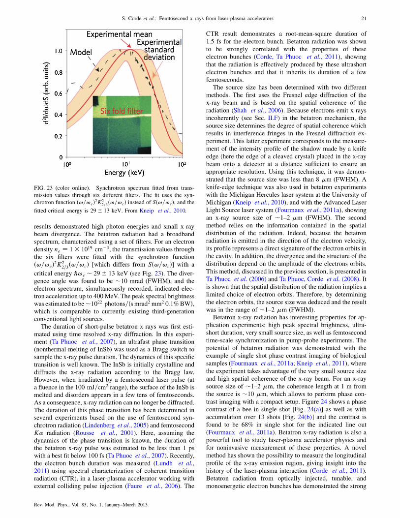
results demonstrated high photon energies and small x-raybeam divergence. The betatron radiation had a broadbandspectrum, characterized using a set of filters. For an electrondensity ne ¼ 1� 1019 cm�3, the transmission values throughthe six filters were fitted with the synchrotron functionð!=!cÞ2K2
2=3ð!=!cÞ [which differs from Sð!=!cÞ] with a
critical energy ℏ!c � 29� 13 keV (see Fig. 23). The diver-gence angle was found to be �10 mrad (FWHM), and theelectron spectrum, simultaneously recorded, indicated elec-tron acceleration up to 400 MeV. The peak spectral brightnesswas estimated to be�1022 photons=ðsmrad2 mm2 0:1%BWÞ,which is comparable to currently existing third-generationconventional light sources.
The duration of short-pulse betatron x rays was first esti-mated using time resolved x-ray diffraction. In this experi-ment (Ta Phuoc et al., 2007), an ultrafast phase transition(nonthermal melting of InSb) was used as a Bragg switch tosample the x-ray pulse duration. The dynamics of this specifictransition is well known. The InSb is initially crystalline anddiffracts the x-ray radiation according to the Bragg law.However, when irradiated by a femtosecond laser pulse (ata fluence in the 100 mJ=cm2 range), the surface of the InSb ismelted and disorders appears in a few tens of femtoseconds.As a consequence, x-ray radiation can no longer be diffracted.The duration of this phase transition has been determined inseveral experiments based on the use of femtosecond syn-chrotron radiation (Lindenberg et al., 2005) and femtosecondK� radiation (Rousse et al., 2001). Here, assuming thedynamics of the phase transition is known, the duration ofthe betatron x-ray pulse was estimated to be less than 1 pswith a best fit below 100 fs (Ta Phuoc et al., 2007). Recently,the electron bunch duration was measured (Lundh et al.,2011) using spectral characterization of coherent transitionradiation (CTR), in a laser-plasma accelerator working withexternal colliding pulse injection (Faure et al., 2006). The
CTR result demonstrates a root-mean-square duration of
1.5 fs for the electron bunch. Betatron radiation was shown
to be strongly correlated with the properties of these
electron bunches (Corde, Ta Phuoc et al., 2011), showing
that the radiation is effectively produced by these ultrashort
electron bunches and that it inherits its duration of a few
femtoseconds.The source size has been determined with two different
methods. The first uses the Fresnel edge diffraction of the
x-ray beam and is based on the spatial coherence of the
radiation (Shah et al., 2006). Because electrons emit x rays
incoherently (see Sec. II.F) in the betatron mechanism, the
source size determines the degree of spatial coherence which
results in interference fringes in the Fresnel diffraction ex-
periment. This latter experiment corresponds to the measure-
ment of the intensity profile of the shadow made by a knife
edge (here the edge of a cleaved crystal) placed in the x-ray
beam onto a detector at a distance sufficient to ensure an
appropriate resolution. Using this technique, it was demon-
strated that the source size was less than 8 �m (FWHM). A
knife-edge technique was also used in betatron experiments
with the Michigan Hercules laser system at the University of
Michigan (Kneip et al., 2010), and with the Advanced Laser
Light Source laser system (Fourmaux et al., 2011a), showing
an x-ray source size of �1–2 �m (FWHM). The second
method relies on the information contained in the spatial
distribution of the radiation. Indeed, because the betatron
radiation is emitted in the direction of the electron velocity,
its profile represents a direct signature of the electron orbits in
the cavity. In addition, the divergence and the structure of the
distribution depend on the amplitude of the electrons orbits.
This method, discussed in the previous section, is presented in
Ta Phuoc et al. (2006) and Ta Phuoc, Corde et al. (2008). It
is shown that the spatial distribution of the radiation implies a
limited choice of electron orbits. Therefore, by determining
the electron orbits, the source size was deduced and the result
was in the range of �1–2 �m (FWHM).Betatron x-ray radiation has interesting properties for ap-
plication experiments: high peak spectral brightness, ultra-
short duration, very small source size, as well as femtosecond
time-scale synchronization in pump-probe experiments. The
potential of betatron radiation was demonstrated with the
example of single shot phase contrast imaging of biological
samples (Fourmaux et al., 2011a; Kneip et al., 2011), where
the experiment takes advantage of the very small source size
and high spatial coherence of the x-ray beam. For an x-ray
source size of �1–2 �m, the coherence length at 1 m from
the source is �10 �m, which allows to perform phase con-
trast imaging with a compact setup. Figure 24 shows a phase
contrast of a bee in single shot [Fig. 24(a)] as well as with
accumulation over 13 shots [Fig. 24(b)] and the contrast is
found to be 68% in single shot for the indicated line out
(Fourmaux et al., 2011a). Betatron x-ray radiation is also a
powerful tool to study laser-plasma accelerator physics and
for noninvasive measurement of these properties. A novel
method has shown the possibility to measure the longitudinal
profile of the x-ray emission region, giving insight into the
history of the laser-plasma interaction (Corde et al., 2011).
Betatron radiation from optically injected, tunable, and
monoenergetic electron bunches has demonstrated the strong
FIG. 23 (color online). Synchrotron spectrum fitted from trans-
mission values through six different filters. The fit uses the syn-
chrotron function ð!=!cÞ2K22=3ð!=!cÞ instead of Sð!=!cÞ, and the
fitted critical energy is 29� 13 keV. From Kneip et al., 2010.
S. Corde et al.: Femtosecond x rays from laser-plasma accelerators 21
Rev. Mod. Phys., Vol. 85, No. 1, January–March 2013

correlation between electron and x-ray properties (Corde, TaPhuoc et al., 2011), showing that betatron radiation can beused to perform noninvasive measurements of some of theelectron beam parameters, such as the normalized transverseemittance of the electron beam (Kneip et al., 2012).
Betatron radiation was also observed in the petawatt re-gime using a laser delivering 300 J within 600 fs pulses(Kneip et al., 2008). In this parameter regime, the laser pulseis much longer than the plasma period and the physicalmechanisms are different. For a long laser pulse (�L �1=!p), electrons can be accelerated and wiggled in the SM-
LWFA and/or DLA regimes, depending on the laser strengthparameter a0. Electrons experience both the transverse focus-ing force of the channel and the electromagnetic field of thelaser. As a consequence, the transverse amplitude of theelectron orbits can be significantly increased due to betatronresonance. The results showed the possibility to producebetatron radiation with a spectrum fitted by the synchrotronfunction Sð!=!cÞ with a critical energy up to ℏ!c ¼14:5 keV [note that in Kneip et al. (2008), their conventionfor ℏ!c leads to a value of 29 keV] and with a divergence of�1 rad. In this experiment, the total number of photons wasfound to be more than 5� 108 photons=ðmrad2 0:1%BWÞ inthe spectral range ½7 keV; 12 keV� and a typical electroncharge of 2 nC was observed with electron energies in the50 MeV range. From these properties, the amplitude ofmotion and the strength parameter K were deduced to be�30 �m and �130, respectively, in agreement with PICsimulations.
E. Scalings and perspectives
The betatron source offers several routes of development interms of number of photons, spectral range, and divergence.According to Sec. IV.B, these quantities scale in the wigglerlimit as (Rousse et al., 2007)
N� / NeN�K / NeN�
ffiffiffiffiffiffiffiffi�ne
pr�; (64)
ℏ!c / �1:5 ffiffiffiffiffine
pK / �2ner�; (65)
�r / K=� / ffiffiffiffiffine
pr�=
ffiffiffiffi�
p; (66)
where N� is the number of betatron periods and Ne is the
number of electrons. As discussed in Sec. IV.B, these for-mulas are valid for time-constant parameters, but can be usedwith the values of the parameters at the dephasing time for therealistic case of an electron being accelerated in the ioncavity. In addition to these formulas, the scalings of theacceleration process are required. Considering the phenome-nological model of the bubble regime described by Lu,Huang, Zhou, Mori, and Katsouleas (2006), Lu, Huang,Zhou, Tzoufras et al. (2006), and Lu et al. (2007), higherelectron energy gain requires lower plasma density. Its scal-ing is given by � ’ �E=mc2 ¼ ð2!2
L=3!2pÞa0 / a0=ne. The
matched spot size condition reads kpw0 ¼ 2ffiffiffiffiffia0
pand the
bubble radius should equal the laser pulse waist rb ¼ w0 /a1=20 n�1=2
e . The number of trapped electrons, obtained from an
energy balance between the electron beam and the bubbleelectromagnetic fields, scales as the ionic charge of the
bubble: Ne / r3bne / a3=20 n�1=2e . The dephasing length scales
as Ld / a1=20 n�3=2e and the betatron period as �u / a1=20 n�1
e ,
such that the number of betatron oscillations obeys N� /n�1=2e . Different electron injection mechanisms can lead to
different scalings for r�, but betatron radiation is optimized
when r� is maximum, and this latter is limited by rb. We
therefore assume that the transverse size of the electron bunchroughly scales as the bubble radius for optimized conditions
for betatron radiation: r� / rb / a1=20 n�1=2e .
The scalings of Eqs. (64)–(66) can then be reformulated asfunctions of a0 and ne as
N� / a5=20 n�3=2e ; (67)
ℏ!c / a5=20 n�3=2e ; (68)
�r / n1=2e ; (69)
while the needed laser energy Elaser / a20w20� obeys
Elaser / a7=20 n�3=2e : (70)
This expression uses the optimal pulse duration c� ¼ 2w0=3corresponding to the situation where the dephasing length Ld
matches the pump depletion length Lpd. These scalings take
into account neither the possible interaction between theelectron beam and the laser pulse nor beam loading effects,and describe the betatron perspectives in the purely bubbleregime. However, they highlight the route toward harderx rays and higher radiated energies: increasing the laser pulsestrength parameter and/or decreasing the density. Equation(70) indicates that it is more efficient in terms of laser energyto decrease the plasma density and not to increase the laserstrength parameter. The efficiency �X of the conversion oflaser energy into x rays, defined as the ratio of the radiated
energy by the laser energy, scales as a3=20 n�3=2e . The betatron
mechanism will become more and more efficient when goingto higher and higher photon energies.
FIG. 24 (color online). Bee imaged with the betatron x-ray beam
with an edge line out indicated by the rectangular area: (a) one laser
shot; (b) 13 laser shots. (c) Line out of the images taken at the
indicated rectangular area. From Fourmaux et al., 2011a.
22 S. Corde et al.: Femtosecond x rays from laser-plasma accelerators
Rev. Mod. Phys., Vol. 85, No. 1, January–March 2013

Petawatt-class lasers and capillaries both allow one todecrease the plasma density. With petawatt lasers producingsub–100 fs pulses, the higher laser energy can be focused intoa larger focal spot matched to the lower plasma densityaccording to kpw0 ¼ 2
ffiffiffiffiffia0
p. For self-injection to occur, a0 �
4–5 is needed, while the self-guided propagation requiresa0 * ðnc=neÞ1=5, where nc ¼ m�0!
2L=e
2 is the critical den-
sity (this condition expresses that energy loss at the front ofthe laser pulse due to pump depletion is higher than the lossdue to diffraction) (Lu et al., 2007). Capillaries allow one toguide the laser pulse over distances much larger than theRayleigh length such that no condition apply on a0. Thistechnique has already been used to accelerate electrons up to1 GeV in a few centimeters capillary (Leemans et al., 2006).Combined with external injection, a strength parameter assmall as a0 ¼ 2 can be used, which permits one again tofocus the laser energy into a larger focal spot and to decreasethe plasma density. A drawback of these natural scalings isthe increase of the x-ray source size and pulse duration as r�,
�r / a1=20 n�1=2e . As a consequence, the peak spectral bright-
ness (number of photons divided by the pulse duration, by thesolid angle, and by the source size in 0.1% spectral band-width) scales as a0=ne. Nevertheless, an external injectioncould provide small duration and therefore better time reso-lution and brightness for application experiments.
Using 15 J of laser energy focused into a gas jet of densityne ¼ 1:1� 1018 cm�3 with a waist w0 ¼ 21 �m and com-pressed to a duration � ¼ 48 fs (300 TW on target), the laserstrength parameter is a0 ¼ 4:4, ensuring self-guiding andself-injection, and trapped electrons reach the maximumenergy of 2.4 GeV after 23 mm of plasma (Rechatin, 2009).Assuming a reasonable value for the betatron amplituder� ¼ 3 �m, we expect K � 30 and x-ray photons emitted up
to ℏ!c � 400 keV, collimated within a typical opening angleof 6 mrad, and containing N�� (1 photon/electron)/betatron
period. On the other hand, a configuration with 3 J of laserenergy, ne ¼ 5:1� 1017 cm�3, w0 ¼ 21 �m, � ¼ 47 fs(60 TW on target) corresponding to a0 ¼ 2 and assisted byexternal guiding (capillaries) and external injection [optical orcolliding pulse injection (Faure et al., 2006) or density gradientinjection (Geddes et al., 2008)] provides the same outputelectron energy of 2.4 GeV after 52 mm of plasma. With thesame value of betatron amplitude r� ¼ 3 �m, x rays are emit-
ted with the following properties: K � 20, ℏ!c � 200 keV,�r � 4 mrad, and N�� (0.7 photon/electron)/betatron period.
Compared to the self-guided self-injected situation, the numberof trapped electrons Ne is 2 times smaller, the number ofbetatron periods N� is 1.4 times higher (see their respective
scalings above), and the total number of emitted photons is2 times smaller, but within a better divergence (�r is 1.4 timessmaller) and for a needed laser power 5 times smaller. For suchconfigurations, the number of betatron photons could reason-ably reach the level of 1010 photons.
Another route toward brighter betatron radiation andhigher photon energies makes use of density-tailored plasmas(Layer et al., 2007) as recently suggested (Ta Phuoc, Esareyet al., 2008). This method relies on the control of the electronorbits by varying the density, and therefore the forces actingon the electrons along the propagation. For appropriatelychosen density modulations, numerical simulations show
that the amplitude of the betatron oscillations r� can be
significantly increased. The basic idea is to freeze the wake-field during a short duration in order to let the electron beamdefocus and acquire larger betatron amplitude. An additionaleffect is that, for large betatron amplitude, the mean longitu-dinal velocity is lowered and electrons dephase slower andcan reach higher energies. In an optimistic configurationdescribed by Ta Phuoc, Esarey et al. (2008), the criticalenergy of the radiation can be increased by a factor of 9,the number of photons by a factor of 5, but with an increaseof the divergence by a factor of 4.
V. PLASMA ACCELERATOR AND CONVENTIONAL
UNDULATOR: SYNCHROTRON RADIATION
Synchrotron radiation can be produced from laser-plasmaaccelerated electrons propagating and oscillating in a conven-tional undulator or wiggler. A conventional undulator or wig-gler is a periodical structure of magnets generating a periodicstatic magnetic field (Clarke, 2004). Figure 25 represents theprinciple of the scheme. Electrons are first accelerated in aplasma accelerator (gas jet, capillary, or steady-state-flow gascell) and then transported into an undulator orwiggler. The sizeof such a device is on the meter scale, with a typical magneticperiod in the centimeter range. Moreover, the values of �u,technologically limited, imply that GeV electrons are neces-sary to produce radiation in the x-ray range. These representthe disadvantages of this scheme, which however is of crucialinterest because it represents a possible route toward theproduction of a compact free-electron laser based on a laser-plasma accelerator (Gruner et al., 2007; Malka et al., 2008;Nakajima, 2008) (see Sec. VII). In the following sections, theelectron orbits in undulators and the main properties of syn-chrotron radiation produced from laser-plasma electronbunches are described in a presently realizable case. After asummary of the experimental results, we conclude with theshort term developments foreseen. For detailed properties ofundulator radiation, such as the angular distribution of indi-vidual undulator harmonics, the different undulator types(planar or helical), the polarization properties, and the spatialor temporal coherence properties, see Clarke (2004),Wiedemann (2007a), and Chao and Tigner (2009).
A. Electron motion
We consider a laser wakefield accelerator producing amonoenergetic electron bunch of energy E ¼ �imc2 with
FIG. 25 (color online). Schematic of the undulator source. A
laser-plasma accelerated electron beam is injected in a conventional
undulator. Electrons oscillate transversally and emit x rays due to
this motion.
S. Corde et al.: Femtosecond x rays from laser-plasma accelerators 23
Rev. Mod. Phys., Vol. 85, No. 1, January–March 2013

velocity directed in the ~ez axis. The simplest model todescribe the electron dynamics in the undulator is to approxi-mate the static magnetic field near the undulator axis by
~B ¼ B0 sinðkuzÞ ~ey; (71)
where ku ¼ 2�=�u with �u the magnetic period of the un-dulator. The equation of motion for a test electron in thisidealized model is given by
d ~p
dt¼ �e ~v� ~B: (72)
The normalized Hamiltonian describing the electron dynam-ics is given by
H ð ~r; ~P; tÞ ¼ � ¼ffiffiffiffiffiffiffiffiffiffiffiffiffiffiffiffiffiffiffiffiffiffiffiffiffiffiffi1þ ð ~Pþ ~aÞ2
q; (73)
where ~P is the normalized canonical electron momentum and~a ¼ �a0 cosðkuzÞ ~ex is the normalized vector potential ver-
ifying ~B ¼ ðmc=eÞr � ~a. H does not depend on x, y, and t.
The transverse canonical momentum ~P? and the normalizedenergy � are therefore conserved. Integrating these constants
of motion with the initial conditions ~P? ¼ 0 and � ¼ �i
leads to, in physical units,
� ¼ cte ¼ �i; (74)
xðzÞ ’ � K
�kusinðkuzÞ; (75)
K ¼ a0 ¼ eB0
kumc: (76)
The general description developed in Sec. II is recovered andthe practical expression of K in terms of experimental pa-rameters and fundamental constants has been obtained. Inparticular, K does not depend on � and the radiation regime(undulator or wiggler) is the same for all electron energies.The strength parameter K is determined by the amplitude ofthe magnetic field B0 and the period �u and is, in practicalunits, given by
K ¼ 0:934�u½cm�B0½T�: (77)
B. Radiation properties
The radiation properties are the same as in Sec. II. Thespectrum of the emitted radiation depends on K. For a smallamplitude of oscillation K � 1, radiation is emitted at thefundamental photon energyℏ!with a narrowbandwidth in theforward direction (� ¼ 0). As K ! 1 harmonics of the funda-mental start to appear in the spectrum, and for K � 1 thespectrumcontainsmany closely spaced harmonics and extendsup to a critical energy ℏ!c. These quantities are given by
ℏ! ¼ ð2�2hc=�uÞ=ð1þ K2=2Þ for K < 1;
ℏ!c ¼ 32K�2hc=�u for K � 1:
(78)
In practical units, this gives
ℏ!½eV� ¼ 2:48� 10�4�2=�u½cm� for K � 1;
ℏ!c½eV� ¼ 1:74� 10�4�2B0½T� for K � 1:(79)
The radiation is collimated within a cone of typical open-ing angle �r ¼ 1=� in the undulator case. For a wiggler, theradiation is collimated within a typical opening angle K=� inthe electron motion plane ð ~ex; ~ezÞ and 1=� in the orthogonalplane ð ~ey; ~ezÞ.
The radiation temporal profile is simply given by theconvolution between the electron bunch temporal profileand the radiation profile from a single electron. For x rays,the radiation length from a single electron lrjNe¼1
¼ N� is in
the nanometer range, much smaller than the typical electronbunch length which is in the micron range, and therefore�rjNe ’ �b. However, for UVand XUV radiation, the slippage
between the radiation and the electron bunch is not neces-sarily negligible, and the radiation duration can be stretchedby the single electron radiation duration. The electron bunchduration depends on the acceleration mechanism and on itstransport from its source to the undulator. Presently, theshortest electron bunches are obtained using a laser-drivenplasma-based accelerator with an external optical injectionmechanism (Faure et al., 2006, 2007; Davoine et al., 2008;Malka et al., 2009; Rechatin, Faure et al., 2009). In thisscheme, electron bunches with rms (root mean square) dura-tion as small as 1.5 fs can be produced (Lundh et al., 2011).However, the necessary transport of the electron bunch in theundulator can deteriorate the duration (and the transverseemittance), because different electrons in the bunch traveldifferent distances. For example, considering usual transportdevices (quadrupoles), placed at �1 m from the laser-plasmaaccelerator, an initially 1-�m-long bunch has its lengthincreased to �10 �m during its transport to an undulatorplaced several meters after the laser-plasma accelerator. Anultracompact transport system, placed as closed as possible tothe plasma source, is required to avoid such a deterioration.
The number of emitted photons follows the expressionsgiven in Sec. II. In practical units, the number of photonsemitted per period and per electron (at the mean photonenergy hℏ!i ¼ 0:3ℏ!c for the wiggler limit) is given by
N� ¼ 1:53� 10�2K2 for K < 1;
N� ¼ 3:31� 10�2K for K � 1:(80)
From these expressions the features of the produced radiationcan be obtained for a realizable case: an electron bunch at anenergy of 1 GeV containing 100 pC and an undulator of 100periods with �u ¼ 1 cm and K ¼ 0:5. The emitted radiationhas a narrow band spectrum centered at EX � 1 keV in theforward direction (� ¼ 0), is collimated within a typicalopening angle of �500 �rad, and contains �2� 108
photons.
C. Numerical results
In this section, the electron motion and the emitted radia-tion are calculated numerically. Both the cases of an undu-lator and a wiggler are considered, with, strength parameterof K ¼ 0:2 and 2, respectively. The magnetic structure has aperiod �u ¼ 1 cm and the test electron propagates in the ~ezdirection with � ¼ 1000 ( ’ 500 MeV). Figure 26 shows theelectron motion along N ¼ 10 oscillation periods (the num-ber of periods of an undulator or wiggler is usually on theorder of 100). The motion, with � constant, consists of a
24 S. Corde et al.: Femtosecond x rays from laser-plasma accelerators
Rev. Mod. Phys., Vol. 85, No. 1, January–March 2013

transverse oscillation at a period �u combined with a longi-tudinal drift. The amplitude of the transverse motion is givenby �uK=2�� (here ’ 1:6� K½�m�). For K ¼ 0:2 and 2 thetransverse excursions are 0.32 and 3:2 �m, respectively.
The spatial distributions of the radiation produced by theelectron undergoing these trajectories are presented on theleft of Fig. 27. For K ¼ 0:2 (top), the radiation has a diver-gence of typical opening angle 1=�� 1 mrad. For K ¼ 2(bottom), the radiation has a divergence of typical openingangle K=�� 2 mrad in the plane of the electron motion and1=�� 1 mrad in the orthogonal direction. The right part ofFig. 27 represents the spectra of the emitted radiation for eachsituation (undulator on the top and wiggler on the bottom).For the undulator case, the spectrum is plotted for threedifferent solid angles of integration (0:3� 0:3, 0:8� 0:8,and 2� 2 mrad2), whereas for the wiggler case it is inte-grated over the overall spatial distribution. For K ¼ 0:2 thespectrum is nearly monochromatic at the energy ℏ!�200 eV in the forward direction, with a width of the emission
line given by �� ¼ �=N (where N ¼ 10 is the number of
oscillation periods), and it is stretched after integration overthe emission angles due to the angular dependence of the
radiated wavelength � ’ ð�u=2�2Þð1þ K2=2þ �2�2Þ [see
Sec. II, Eq. (5)]. For K ¼ 2 the spectrum becomes broadband
with a critical energy of around 300 eV. An estimate of the
total photon number can be obtained on the basis of thenumber of electrons that are currently accelerated in a
laser-plasma accelerator. Assuming 1� 108 electrons gives�105 photons at 200 eV within a spectral bandwidth of 10%
in the undulator case (selection of the 0:3� 0:3 mrad2 solidangle). In the wiggler case there are �5� 103 photons/0.1%BW at 600 eV and a total photon number in the range 107–8.
D. Experimental results
Synchrotron facilities have been developed worldwide and
have been providing x-ray radiation to users for severaldecades. These installations are very robust and the x-ray
beams have high quality. They are based on conventional
accelerator technology.The first demonstration of the production of synchrotron
radiation from laser-accelerated electrons was performed by
Schlenvoigt et al. (2008a); (2008b). In this experiment, laser-produced electron bunches between 55 and 75 MeV were
injected, without transport, into a 1-m-long undulator havinga period �u ¼ 2 cm and a strength parameter K ¼ 0:6. Theyobtained synchrotron radiation in the visible and infrared part
of the spectrum (the wavelength was in the range 700–1000 nm) and estimated a peak spectral brightness of 6:5�1016 photons=ðsmrad2 mm2 0:1%BWÞ and a total number ofphotons of 2:8� 105. The radiation wavelength was observedto scale with the electron bunch energy as expected.
More recently, synchrotron radiation from laser-plasmaaccelerated electrons was produced up to �130 eV (Fuchs
et al., 2009). This experiment represents an important
advance compared to the first demonstration. First, a stableelectron beam was produced by the interaction of a laser at
�2� 1018 W cm�2 with a 15-mm-long hydrogen-filledsteady-state-flow gas cell (Osterhoff et al., 2008). The
electron bunch was in the 150–220 MeV energy range and
contained 30 pC. Second, a pair of miniature permanent-magnet quadrupole lenses was implemented in order to
make the electron beam collimated at a selected energy andto transport it through a 30-cm-long undulator having a
period �u ¼ 5 mm and a strength parameter K ¼ 0:55(Eichner et al., 2007). Thanks to the high energy of theelectron and the short period of the undulator, the radiation
was produced down to the XUV range with a tunable wave-length. Note that this tunability resides in the possibility to
select, with the magnetic lenses, a specific electron energy inthe 150–220 MeV range (electrons with different energies are
not collimated and will not produce a collimated radiation
beam). The radiation was analyzed using a spectrometerbased on a transmission grating. The fundamental wavelength
(� ¼ 18 nm) as well as the second harmonic were measured.In addition, the parabolic dependence of the radiation wave-
length on the angular direction � ¼ ð�u=2�2Þð1þ K2=2þ
�2�2Þ was observed with good agreement. This soft-x-rayundulator source delivers �105 photons per shot integrated
FIG. 26 (color online). Electron trajectories. The orbit is plotted
as a solid line for the undulator case (K ¼ 0:2) and dashed line for
the wiggler case (K ¼ 2). At the entrance, the electron has � ¼1000 and ~p ¼ ffiffiffiffiffiffiffiffiffiffiffiffiffiffiffi
�2 � 1p
~ez in both situations. The undulator or
wiggler is ten periods long.
FIG. 27 (color online). On the left is represented the angular
distributions of the radiation (radiated energy per unit solid angle)
and the corresponding spectra are shown on the right (in number of
photons per 0.1% bandwidth, per electron, and per shot). The
undulator case, K ¼ 0:2, is on the top whereas the wiggler case,
K ¼ 2, is on the bottom. In the first situation, three different solid
angles of integration have been considered to highlight the stretch-
ing of the spectrum. In the wiggler situation, the integration is
performed over the total angular distribution.
S. Corde et al.: Femtosecond x rays from laser-plasma accelerators 25
Rev. Mod. Phys., Vol. 85, No. 1, January–March 2013

over the fundamental within a detection cone of �0:7 mrad,corresponding to a relative bandwidth of 30% (FWHM). Thepeak spectral brightness was estimated to be �1:3�1017 photons=ðsmrad2 mm2 0:1%BWÞ.
E. Perspectives
The experiments performed open perspectives for the pro-duction of a tunable synchrotron-type x-ray source. However,further progress is necessary to produce tunable and reproduc-ible monoenergetic electron bunches in the GeV range. Theforeseen possibilities to achieve these features rely on the useof higher power lasers (petawatt) and/or capillaries. This gainin laser power compared to actual systems would allow one todecrease the plasma density, increase the acceleration length,and as a consequence increase the electron energy. The use ofan external injection will be required as well to easily controlthe electron energy [optical injection (Faure et al., 2006) orplasma density gradient injection (Geddes et al., 2008), aspresented in Sec. III]. Finally, a compact electron transportsystem from the plasma source to the undulator has to beimplemented in order to avoid deterioration of the electronbeam parameters and to reduce the radiation source size.
In the short term, this approach will allow university-scalelaboratories to access x-ray sources with angstrom wave-lengths and sub-10-fs pulse durations for four-dimensionalimaging with atomic resolution. Besides this future develop-ment, the main and more challenging perspective relies on thepossibility to produce a free-electron laser based on a laser-plasma accelerator combined with an undulator. This radia-tion source has a brightness orders of magnitude higher than asynchrotron, thanks to the coherent addition of radiation fromeach electron. Electron bunches produced with laser-plasmaaccelerators are interesting candidates for a FEL source sincesuch bunches are naturally femtosecond and have high cur-rent. In Sec. VII, we discuss the principle of the free-electronlaser and its possible realization using electrons from laser-plasma accelerators which could have revolutionary impactsin many fields of science, technology, and medicine.
VI. ELECTROMAGNETIC WAVE UNDULATOR:
NONLINEAR THOMSON SCATTERING AND THOMSON
BACKSCATTERING
In this section, the production of femtosecond x-ray andgamma-ray beams from electrons oscillating in an electro-magnetic wave is reviewed. The involved radiative mecha-nism is referred to as Compton scattering. In the frameworkof quantum electrodynamics, it corresponds to the absorptionof one (linear) or several (nonlinear) photons by an electronand to the emission of a single photon.When, in the rest frame,the electron experiences a negligible recoil (which happenswhen ℏ! � mc2 in the rest frame), the mechanism is referredto as Thomson scattering, the low-energy limit of Comptonscattering. In the following, we consider Thomson scatteringand use a classical description, assuming that quantum andradiation reaction effects are negligible (see Sec. II.G).
At the laser-plasma interaction, two schemes of femto-second x-ray or gamma-ray sources based on Thomson scat-tering have been proposed and demonstrated. Based on the
same principle, the two methods differ by the initial energy ofthe electron and the intensity of the laser pulse scattering offthe electrons.
In the first scheme, electrons are initially at rest and laserwakefield acceleration is not invoked. Here Thomson scat-tering occurs in a highly nonlinear regime. Indeed, for a0 �1, electrons have a highly nonlinear motion and the emittedradiation consists of high-order harmonics. The harmonicspectrum can extend up to the x-ray range. This schemeoffers simplicity and the possibility to produce a large x-rayphoton flux because the number of electrons participating inthe emission is on the order of the number of electrons in thefocal volume. However, reaching the keV energy range re-quires very high laser strength parameters, typically a0 > 10.
The second scheme relies on Thomson scattering an in-tense laser pulse off a counterpropagating relativistic electronbeam. Here the x-ray range is reached even with modest-energy electrons thanks to two successive Doppler shifts. Inthe average rest frame of the electrons, moving with a rela-tivistic factor �� with respect to the laboratory frame, thefrequency of the incident electromagnetic wave (the laserpulse) becomes !0
i ¼ 2 ��!i. The light is scattered by the
electrons at the same frequency !0r ¼ !0
i (for a low intensity
electromagnetic wave corresponding to the linear Thomsonscattering and the undulator regime) or at harmonics !0
r ¼n!0
i (for high intensity corresponding to nonlinear Thomson
scattering and the wiggler regime). When observed in thelaboratory frame, this reflected wave is Doppler shifted andits frequency becomes !r ¼ 4 ��2!i (linear Thomson back-scattering) or its harmonics (nonlinear Thomson backscatter-ing). This scheme offers the possibility to produce x rays inthe keV range even with modest energy electrons (tens ofMeV) or gamma rays if 100 MeV range electrons are used.
In the following sections the two schemes are discussed.For both, electron orbits, radiation properties, numerical, andexperimental results are presented.
A. Nonlinear Thomson scattering
In this section, the production of femtosecond x-ray radia-tion from electrons initially at rest is discussed. In thisscheme, Thomson scattering occurs in a strongly nonlinearregime and electrons are directly accelerated and wiggledwithin an intense laser field. This scheme offers the possibil-ity to produce a large photon flux because the number ofelectrons participating in emission can be much larger thanthe number of electrons trapped and accelerated in a laser-plasma accelerator. It is of the order of the number ofelectrons in the focal volume. However, producing x-rayradiation requires a laser strength parameter a0 much greater
than unity. Indeed, in that regime, the term �e ~v� ~B of theLorentz force, negligible at low intensity, becomes compa-
rable to the �e ~E component and the motion is a nonlinearfunction of the driving field in addition to becoming rela-tivistic. The electron motion is no longer harmonic and theradiation emitted consists of high-order harmonics forminga broadband spectrum that extends up to the x-ray range.The spectrum shifts to higher energies as a0 increases. Thisradiative mechanism is commonly called nonlinear or rela-tivistic Thomson scattering. The principle of this source is
26 S. Corde et al.: Femtosecond x rays from laser-plasma accelerators
Rev. Mod. Phys., Vol. 85, No. 1, January–March 2013

displayed in Fig. 28. It simply consists of focusing anintense laser on a target (here an underdense plasma isconsidered).
In the following sections, the properties of nonlinearThomson scattering5 are reviewed. The electron orbit is
derived in the case of a circularly polarized laser pulse,because it leads to a situation where the concept of wiggling,developed in Sec. II, can be applied. For a linearly polarizedlaser pulse, analytical results can be easily obtained for theelectron orbit, but not for the radiation features. In that latter
case, the electron movement does not correspond to a trans-verse wiggling around a relativistic drift motion along thepropagation axis. The electron performs violent accelerationsfrom � ¼ 1 to � ¼ 1þ a20=2 and decelerations to � ¼ 1 for
each half period of the movement. The emitted radiationcomes from the longitudinal acceleration, and not from thetransverse one anymore. Hence, in Secs. VI.A.1 and VI.A.2analytical expressions are derived for the circular polarization
but the linear polarization will be discussed in the numericalSec. VI.A.3. After a brief summary of the experimentalresults obtained, we finally conclude with the short-termdevelopments foreseen.
1. Electron orbit in an intense laser pulse
We consider a test electron initially at rest (�i ¼ 1) sub-mitted to an intense laser pulse modeled by a circularlypolarized plane electromagnetic wave propagating along
the ~ez axis, with a wave vector ~ki ¼ 2�=�L ~ez and a
frequency !i ¼ 2�c=�L, and with a normalized vectorpotential given by
~a ¼ a0
�1ffiffiffi2
p cosð!it� kizÞ ~ex þ 1ffiffiffi2
p sinð!it� kizÞ ~ey�:
(81)
The equation of motion of the test electron is
d ~p
dt¼ �eð ~Eþ ~v� ~BÞ: (82)
All quantities with a hat are normalized by the followingchoice of units: m ¼ c ¼ e ¼ !i ¼ 1. The Hamiltoniandescribing the test electron dynamics in the electromagneticwave is written as
H ð ~r; ~P; tÞ ¼ � ¼ffiffiffiffiffiffiffiffiffiffiffiffiffiffiffi1þ ~p2
q¼
ffiffiffiffiffiffiffiffiffiffiffiffiffiffiffiffiffiffiffiffiffiffiffiffiffiffiffi1þ ð ~Pþ ~aÞ2
q: (83)
This system of an electron in a electromagnetic plane waveis integrable and action-angle variables can be found tosolve the electron motion. Here, for simplicity, we analyzethe symmetries of the system to directly yield the conservedquantities according to Noether theorem. The Hamiltonian
H depends on the canonical momentum ~P and on thepotential vector ~að’Þ through the variable ’ ¼ t� z.
Hence H is independent of x and y, which implies thatthe transverse canonical momentum is a constant of motion.The first constant of motion reads
~P? ¼ ~p? � ~a ¼ ~0: (84)
In addition, H depends on t and z only through ’ ¼ t� z.
Thus @H =@t ¼ �@H =@z, which leads to the second con-stant of motion C,
�� pz ¼ C: (85)
For an electron initially at rest, C ¼ 1, and the test electronorbit is obtained by integrating the constants of motion,
xð’Þ ¼ a0ffiffiffi2
p sinð’Þ; (86)
yð’Þ ¼ � a0ffiffiffi2
p cosð’Þ; (87)
zð’Þ ¼ a204’; (88)
� ¼ 1þ a204: (89)
The electron motion in the laser field consists of a drift in thelongitudinal direction combined with a transverse oscilla-tion. The electron orbit is mainly longitudinal and relativ-istic for a0 > 1 while it is essentially transverse andnonrelativistic for a0 < 1. For a0 < 1, the test electronmotion is a simple nonrelativistic dipole motion which isnot relevant for the production of x rays since radiation isemitted at the same wavelength as the incident field. Fora0 > 1, the longitudinal motion becomes relativistic andnonlinear effects and Doppler shift occur. In the following,the interesting nonlinear case a0 > 1, which results in thegeneration of smaller wavelength radiation than the incidentlaser pulse, is studied.
FIG. 28 (color online). Schematic of the nonlinear Thomson
scattering source. A free electron is submitted to a relativistic laser
pulse (a0 � 1). It is simultaneously accelerated and wiggled, and
emits XUV radiation due to this motion. This illustrates the motion
of an electron in the case of a linearly polarized laser pulse.
5For an overview of the subject see Vachaspati, (1962), Brown
and Kibble (1964), Sarachik and Schappert (1970), Bardsley,
Penetrante, and Mittleman (1989), Castillo-Herrera and Johnston
(1993), Esarey, Ride, and Sprangle (1993), Esarey, Ting et al.
(1993), Salamin and Faisal (1996), Gibbon (1997), Shen et al.
(1997), Ueshima et al. (1999), He et al. (2002), Lau et al. (2003),
and Tian et al. (2006).
S. Corde et al.: Femtosecond x rays from laser-plasma accelerators 27
Rev. Mod. Phys., Vol. 85, No. 1, January–March 2013

The period of the motion is given by
�u ¼ a204�L: (90)
The electron orbit is similar to the standard orbits discussed inSec. II since the normalized energy � is constant. However,the trajectory takes place in three dimensions and is helical.The qualitative regime and the angular distribution can bederived from the parameters KX ¼ �c X and KY ¼ �c Y
which are given by
KX ¼ KY ¼ 4ffiffiffi2
pa0
ð1þ a20=4Þ ’ a0=ffiffiffi2
p; (91)
where c X and c Y are the maximum deflection angles of theorbits in the ~ex and ~ey directions.
2. Radiation properties
For a0 > 1, the relativistic electron motion describedabove leads to the emission of nonlinear Thomson scatteringradiation whose features can be calculated within the frame ofthe general formalism of the radiation from a moving charge.As seen in Sec. II, the spectrum of the produced radiationdepends on the parameter K. According to the above expres-sions of KX and KY , the motion is driven in the wigglerregime since the nonlinear case a0 > 1 is considered. Thespectrum is broadband and extends up to the critical energy
ℏ!c ¼ 3
2�3ℏ
c
; (92)
where ¼ ð�L=2�Þða0=ffiffiffi2
p þ ffiffiffi2
pa30=16Þ ’ ð�L=2�Þ�ffiffiffi
2p
a30=16 is the instantaneous radius of curvature of the
electron orbit obtained from the trajectory. Basically, thecritical energy grows as a30 for a0 � 1. In practical units, it
reads for a0 � 1
ℏ!c ½eV� ¼ 0:3a30
�L ½�m� : (93)
Being an emission from a relativistically moving electron,nonlinear Thomson scattering radiation is emitted in thedirection of the electron velocity and has the same symmetryas the electron orbit. For circular polarization, the radiation isemitted symmetrically around the laser propagation axis at
an angle � ’ 2ffiffiffi2
p=a0, within a typical angular width �� ¼
1=� ’ 4=a20.The number of photons can be estimated by integrating,
over one oscillation period, the expression of the radiated
power PðtÞ ¼ ðe2=6��0cÞ�2½ðd ~p=dtÞ2 � ðd�=dtÞ2� in whichthe trajectory calculated above is inserted. In practical units,the number of photons emitted at the mean energy hℏ!i ¼0:3ℏ!c per one electron undergoing one oscillation period is,for a0 � 1,
N� ¼ 4:68� 10�2a0: (94)
From the above expressions an estimation of the radiationproperties can be obtained for a typical parameter regime.The laser pulse is focused along a Rayleigh length zr ¼500 �m with a0 ¼ 10, and has a duration of 20 fs FWHMand a wavelength �L ¼ 800 nm. The period of the electron
motion is �u � 20 �m and the electron executes about �8oscillations within the laser pulse (FWHM). The criticalenergy of the radiation is ℏ!c � 400 eV. The emission isemitted at an angle �� 280 mrad with respect to the laserpropagation axis. For a plasma density of 1� 1018 cm�3, andif we consider that the number of electrons participating tothe emission is the number of electrons in the focal volume�10� 10� 1000 �m3 (which is equal to 1011 electrons),the number of x-ray photons per shot is �4� 1011.
3. Numerical results
The features of the radiation have been described so far fora free electron submitted to a circularly polarized plane wavefor which the concept of wiggling applies and analyticalsolutions are straightforward. In this section, the case of alinearly polarized laser field is studied using numerical simu-lations. Electron orbits and radiation features are presented.
We consider a laser pulse with a Gaussian temporal profile,whose normalized vector potential reads
~a ¼ a0 exp½�ð2 ln2Þðz� ctÞ2=c2�2� cosð!it� kizÞ ~ex:(95)
The laser pulse duration (FWHM) is � ¼ 20 fs and thepolarization is linear along the ~ex direction. The test electronis initially at rest. Figure 29 displays the electron orbits fora0 ¼ 5 and 10 and the evolution of the relativistic factor ofthe electron � along its motion. The trajectory consists ofsuccessive straight lines with violent longitudinal accelera-tion or deceleration, the velocity vanishing at each corner.The electron acquires energy in the tens of MeV range whileoscillating in the laser pulse, and is again at rest once the laserhas passed. There is no net energy gain.
The radiation has been calculated using the general for-mula (1) in which the orbits calculated above are inserted. InFig. 30, the spatial distribution of the radiated energy isrepresented. Because the polarization is linear, the radiationconsists of two lobes corresponding to the two directionspointed by the straight lines of the orbit. These two lobesform, with respect to the laser propagation axis, an angle
FIG. 29 (color online). Top: The electron orbit in an intense
linearly polarized laser pulse with a0 ¼ 5 (solid line) and a0 ¼10 (dashed line). Bottom: The � factor as a function of the
longitudinal position for each case. The electron is initially at rest
and is submitted only to the linearly polarized laser pulse whose
temporal profile is Gaussian with 20 fs duration (FWHM).
28 S. Corde et al.: Femtosecond x rays from laser-plasma accelerators
Rev. Mod. Phys., Vol. 85, No. 1, January–March 2013

�X � 450 mrad for a0 ¼ 5 and �X � 230 mrad for a0 ¼ 10.As expected, the radiation is more collimated for stronger a0.Figure 31 displays the spectra of the radiation integrated overthe spatial distribution (the photon number per 0.1% band-width per electron and per shot). An estimate of the totalphoton number can be obtained assuming that all electrons inthe focal volume participate to the emission. Assuming afocal volume of dimension 10� 10� 1000 �m3 and adensity of 1018 cm�3 gives 1011 electrons which radiate�107 photon=ð0:1%BW=shotÞ at 50 eV for a0 ¼ 5 and�1:5� 107 photon=ð0:1%BW=shotÞ at 400 eV for a0 ¼10. Comparing these numerical results with the analyticalexpressions obtained for the circular polarization, it appearsthat the spectral properties depend on the observation angle(see the inset of Fig. 31). The shape of the spectrum at themaximum angle of emission is not synchrotronlike, because itdoes not correspond to a wiggling motion. The radiation forlinear polarization is due to the longitudinal acceleration from� ¼ 1 to � ¼ 1þ a20=2 and deceleration to � ¼ 1 occurring
for each straight line section of the motion. The time profile
of the radiated field in a single straight line section consists ofa double peak structure: the first corresponds to the momentwhen the acceleration is maximal, and the second to themoment when the deceleration is maximal. This complexbehavior is at the origin of the spectral modulation observedat the maximum angle of emission in the inset of Fig. 31 (Leeet al., 2003).
It is important to note that the most simple case of non-linear Thomson scattering has been considered. For a moreaccurate description of the mechanism, several effects mustbe taken into account. In the tightly focused case, the exactlaser field can strongly modify the electron orbit. In particu-lar, the electron is expelled from the high-intensity region.This results in a radial drift and limits the number of electronoscillations in the high-intensity regions. Therefore, the radi-ated energy is smaller than in the ideal case and the diver-gence of the x-ray beam is higher and broadened. Thepresence of the ions from the plasma, or, more generally,the collective fields of the plasma, can as well have a signifi-cant impact on the electron orbit. They can reduce thelongitudinal drift or accelerate the electrons. In the firstcase, the longitudinal drift being reduced, the divergence isincreased. Oppositely, if the electron gains energy from theplasma, the radiation becomes more collimated. Finally, thelaser pulse propagates in the plasma with a group velocity vg
smaller than c, which can strongly modify the electron orbit ifthe electron longitudinal velocity vz becomes comparable orgreater than vg.
4. Experimental results
While nonlinear Thomson scattering was anticipated in the1960s (Vachaspati, 1962; Brown and Kibble, 1964; Sarachikand Schappert, 1970), the first experimental demonstration ofnonlinear Thomson scattering was performed in 1998 only(Chen, Maksimchuk, and Umstadter, 1998). Using a 4 TWlaser pulse with a duration of 400 fs, �L ¼ 1 �m, and a0 � 2,focused into a helium gas jet with a density of a few1019 cm�3, nonlinear Thomson scattering radiation was ob-served for the first time. The measured radiation followed thespecific features of nonlinear Thomson scattering and otherradiative processes were ruled out. In particular, the spatialdistributions measured were consistent with the nonlinearThomson scattering properties obtained from the pictureof the single free electron submitted to a plane wave.In this experiment, radiation was detected at wavelengthsup to the third harmonic of the laser (few eV range).The efficiency was estimated to be of the order of a few10�4 photons per electron per pulse. In latter experiments(Banerjee et al., 2002; Banerjee et al., 2003), the nonlinearThomson scattering radiation was observed up to the 30thharmonic with a spatial distribution collimated in the direc-tion of the laser propagation axis (and maximum on axis, incontradiction with the single free-electron model). In 2003,thanks to the advent of high-intensity lasers, nonlinearThomson scattering was demonstrated in the XUV range(Ta Phuoc et al., 2003; Ta Phuoc, Rousse et al., 2003; TaPhuoc, Burgy, Rousseau, and Rousse, 2005). This experimentwas based on the interaction of a 50 TW laser (with a0 � 5,30 fs, 800 nm) and a helium gas (density in the range1018–1019 cm�3). The experimental setup is presented in
FIG. 30 (color online). Spatial distribution of the nonlinear
Thomson scattering, corresponding to trajectories of Fig. 29. The
radiated energy per unit surface in the plane situated at 1 m from the
source and perpendicular to the propagation axis is represented. On
the top is the case a0 ¼ 5 and on the bottom the case a0 ¼ 10.
FIG. 31 (color online). Nonlinear Thomson scattering spectrum,
integrated over angles and corresponding to the trajectories of
Fig. 29. The number of photons per 0.1% bandwidth for one electron
is displayed for the two cases: a0 ¼ 5 in the solid line and a0 ¼ 10in the dashed line. The spectrum near the maximum angle of
emission is represented in the inset for the case a0 ¼ 10.
S. Corde et al.: Femtosecond x rays from laser-plasma accelerators 29
Rev. Mod. Phys., Vol. 85, No. 1, January–March 2013

Fig. 32. The laser was focused within a 6 �m focal spot(FWHM) onto the front edge of a supersonic helium gas jet(3 mm in diameter). Radiation was collected using a grazingincidence spherical mirror and spectrally analyzed using atransmission grating. The whole system was mounted on arotation stage centered on the gas jet in order to measure thespatial distribution of the radiation. Nonlinear Thomson scat-tering radiation was observed in the few tens of eV range upto 1 keV using a set of filters (Al, Zr, Ni, and Be). As atprevious experiments, radiative mechanisms others than non-linear Thomson scattering were ruled out by the variations ofthe XUV signal as a function of experimental parameters. Thesignal was found to increase linearly with the plasma density,the radiation was anisotropic and the energy range fitted whatis expected for nonlinear Thomson scattering.
However, the results differ from the expected emissionwith the model of free electrons in a plane electromagneticwave. The radiation spatial distribution, presented in Fig. 33(left), was collimated within a large angle (within a cone ofhalf angle �30 deg ) and was maximum on axis instead ofconsisting in two lobes centered at þ23 deg and �23 deg.This result can be explained considering the multitude ofelectron orbits, the focusing of the laser, and the effect of
plasma fields. This was supported by the fact that electrons atrelativistic energies were observed during the experiment. Inaddition, laser filamentation was observed (Faure et al.,2002; Thomas et al., 2007; Thomas et al., 2009), indicatinga complex propagation of the laser.
The spectrum, measured on axis in a limited spectral range(30–120 eV), is presented in Fig. 33 (right). The measurementwas performed using a transmission grating. In the inset ispresented the spectrum measured with filters (Al, Zr, Ni, andBe) over a larger bandwidth and the number of photons. Theradiation detected was in the spectral range expected fornonlinear Thomson scattering. A total of 1010 photons pershot were measured (integrated over the spectrum and thespatial distribution).
5. Perspectives
Nonlinear Thomson scattering from the laser-plasma in-teraction remains a complex research topic and only a fewexperiments have been performed. Important numerical andexperimental work has to be done to understand the mecha-nism. This research will be motivated by the fact that thissource of radiation can become a powerful x-ray source.Indeed, the development of petawatt-class lasers will opennovel perspectives for nonlinear Thomson scattering.Assuming that a0 ¼ 20 can be reached, the produced radia-tion is expected to have the following features. The source isextended from the XUV to the x-ray part of the spectrum withphoton energies up to �10 keV. In addition, the number ofphotons will be significantly increased: �1 photon per elec-tron, per period, and per shot, and the radiation will becollimated within a half angle of �150 mrad. Such a sourcehas the main advantage to be very simple to realize. Furtherdevelopments would rely on the control of the preaccelerationof the electron inside the plasma in order reduce the diver-gence of the x-ray beam, enhancing the brightness. Flattop orannular transverse laser profile should be also interesting tomaintain electrons in the high-intensity regions and increasethe number of x-ray photons. Finally, several groups reportedon the possibility to produce attosecond pulses via nonlinearThomson scattering (Lee et al., 2003; Lan, Lu, and Cao,2006). In fact, the nonlinear Thomson scattering from a singleelectron is naturally a train of attosecond pulses (Lee et al.,2003). However, when summing the radiation from allelectrons, the property disappears unless electrons radiatecoherently (instead of incoherent radiation, as presentedthroughout this section). If this latter condition is satisfied,it becomes possible to generate single intense attosecondpulse (Lan, Lu, and Cao, 2006). To fulfill the coherencecondition, the use of ultrathin solid targets has been suggested(Lee, Kim, and Kim, 2005). A scheme named ‘‘lasetron’’ forgenerating coherent zeptosecond pulses has also been pro-posed by Kaplan and Shkolnikov (2002), and is based on thewiggling of electrons in a subwavelength-size solid particleor thin wire submitted to two counterpropagating circularlypolarized petawatt laser pulses.
B. Thomson backscattering
X-ray or �-ray radiation can be produced by scattering anelectromagnetic wave off a counterpropagating relativistic
FIG. 32 (color online). Experimental setup for the nonlinear
Thomson scattering experiment. Radiation is produced from the
interaction of a laser pulse with a0 � 5 and a helium gas jet.
Radiation is collected using a grazing incidence spherical mirror
and spectrally analyzed using a transmission grating. Filters are
used to block the infrared light and to select a specific spectral
range. To scan the angular distribution of the radiation, the whole
system is mounted on a rotation stage centered on the gas jet.
FIG. 33 (color online). On the left is represented the angular
dependence of the radiated energy recorded experimentally by
rotating the whole detection system. The spectrum of the radiation
on axis is given in logarithmic scales on the right of the figure and
the inset shows the total number of photons integrated over several
spectral bands determined by the choice of filters (the horizontal
extension of the lines indicates the spectral band).
30 S. Corde et al.: Femtosecond x rays from laser-plasma accelerators
Rev. Mod. Phys., Vol. 85, No. 1, January–March 2013

electron bunch. This scheme was first proposed in 1963(Arutyunian and Tumanian, 1963; Milburn, 1963) and rein-vestigated in the 1990s thanks to the advance in laser tech-nology and high-brightness electron accelerators, suggesting
the possibility to realize a source of high-brightness pulsedx rays or �-rays (Sprangle et al., 1992; Esarey, Ride, andSprangle, 1993; Esarey, Sprangle et al., 1993; Kim,Chattopadhyay, and Shank, 1994; Ride, Esarey, and Baine,1995; Esarey, Ride et al., 1996; Hartemann and Kerman,1996; Hartemann et al., 1996; Yang et al., 1999; Hartemannet al., 2001; Hartemann, 2002; Li et al., 2002; Gao, 2004;
Krafft, Doyuran, and Rosenzweig, 2005). More recently,when the research on electron acceleration from laser-plasmainteraction became mature, it was proposed to use theselaser-plasma accelerated electron bunches to develop an all-optically driven scheme (Catravas, Esarey, and Leemans,2001; Hafz et al., 2003; Leemans et al., 2005; Tomassiniet al., 2005; Hartemann et al., 2007). The principle of this
scheme is represented in Fig. 34. Two laser pulses are re-quired; the first drives the plasma accelerator, as discussed inSec. III, and the second scatters off the accelerated electrons.In order to derive the typical properties and analytical fea-tures of the Thomson backscattered radiation, the electrondynamics in a counterpropagating laser pulse in the simplestmodel of plane electromagnetic wave is presented. Then,
numerical and experimental results are discussed. Foreseenperspectives of this method are described in the conclusion.
1. Electron orbit in a counterpropagating laser pulse
We consider a laser-plasma accelerator producing a mono-energetic electron bunch of energy E ¼ �imc2 with a velocitydirected along ~ez (toward the positive values). The counter-propagating laser pulse is modeled by a linearly polarized
plane electromagnetic wave of wave vector ~ki ¼ �2�=�L ~ezand frequency !i ¼ 2�c=�L, and with a normalized vector
potential given by ~a ¼ a0 cosð!itþ kizÞ ~ex. The equation of
motion of the test electron and the Hamiltonian H describingthe test electron dynamics in the electromagnetic wave aregiven by Eqs. (82) and (83). We use the same normalizedunits, with the choice m ¼ c ¼ e ¼ !i ¼ 1. As inSec. VI.A.1, the system is integrable and action-angle varia-
bles can be found to solve the electron motion. Here weanalyze the symmetries of the system to directly yield theconserved quantities according to Noether theorem. The
Hamiltonian H depends on the canonical momentum ~Pand on the potential vector ~að’Þ through the variable ’ ¼tþ z. Hence H is independent of x and y, which implies thatthe transverse canonical momentum is a constant of motion.In our problem, it is assumed that the electron has a velocitydirected along ~ez exclusively before entering the laser pulse.Therefore the first constant of motion reads
~P? ¼ ~p? � ~a ¼ ~0: (96)
In addition, H depends on t and z only through ’ ¼ tþ z.
Thus @H =@t ¼ @H =@z, which leads to the second constantof motion C,
�þ pz ¼ C: (97)
The constant C is obtained using the initial conditions � ¼�i, pz ¼
ffiffiffiffiffiffiffiffiffiffiffiffiffiffiffi�2i � 1
q. The integration of the constants of motion
gives the electron orbit
xð’Þ ¼ a0C
sinð’Þ; (98)
yð’Þ ¼ 0; (99)
zð’Þ ¼�1
2� 1þ a20=2
2C2
�’� a20
8C2sinð2’Þ; (100)
�ð’Þ ¼ C
2þ 1þ a20cos
2ð’Þ2C
; (101)
where C ¼ �i þffiffiffiffiffiffiffiffiffiffiffiffiffiffiffi�2i � 1
q¼ 2�i � 1=ð2�iÞ þ oð1=�2
i Þ.The trajectory obtained cannot exactly take the form
xðzÞ ¼ K=ð�kuÞ sinðkuzÞ corresponding to the standard sinu-soidal trajectory studied in Sec. II. Here � is not constantalong the orbit and Eq. (97) implies that � and pz varyoppositely. The oscillation motion z takes, however, a formsimilar to the sinusoidal trajectory, leading to the samecharacteristic figure-eight motion in the average rest frameof the electron. The description of Sec. II can be recoveredwith the approximation ’ ’ 2z ’ 2t. The counterpropagatinglaser pulse can be seen as an undulator with a spatial periodgiven by
�u ¼ �L=2; (102)
and a strength parameter K given by
K ¼ a0 ¼ 0:855ffiffiffiffiffiffiffiffiffiffiffiffiffiffiffiffiffiffiffiffiffiffiffiffiffiffiffiffiffiffiffiffiffiffiffiffiffiffiffiffiffiffiffiffiffiffiffiffiffiI½1018 W=cm2��2
L½�m�q
: (103)
2. Radiation properties
The qualitative features of the radiation remain the same asin Sec. II and can be parametrized by K, �u, and � ’ �i (fora0 � �i). The spectrum of the emitted radiation depends onthe amplitude of the parameter K. For K � 1, the electro-magnetic wave acts as an undulator. In the average rest frameof the electron, Thomson scattering occurs in the linearregime. In the laboratory frame, the radiation is emittedat the Doppler shifted fundamental frequency correspondingto a photon energy ℏ! in the forward direction (� ¼ 0). As
FIG. 34 (color online). Schematic of the all-optically driven
Thomson backscattering source. A laser-plasma accelerated elec-
tron beam is injected in a counterpropagating laser pulse. Electrons
oscillate transversally and emit x rays or � rays due to this motion.
S. Corde et al.: Femtosecond x rays from laser-plasma accelerators 31
Rev. Mod. Phys., Vol. 85, No. 1, January–March 2013
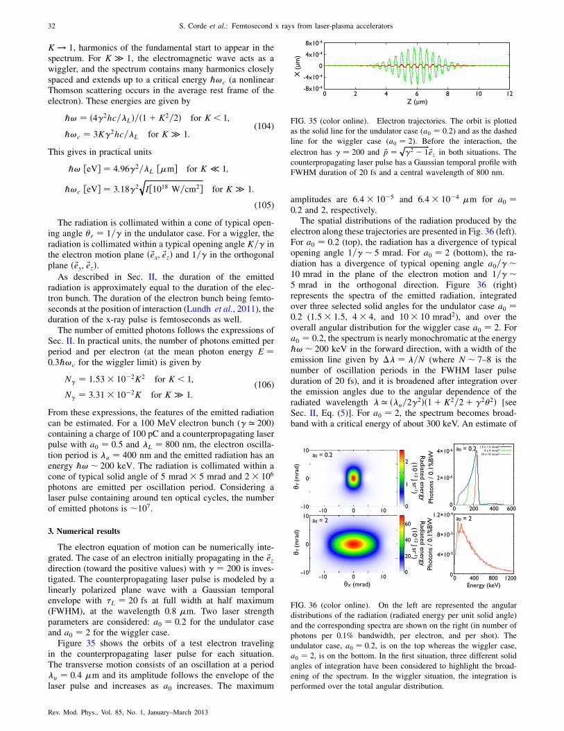
K ! 1, harmonics of the fundamental start to appear in thespectrum. For K � 1, the electromagnetic wave acts as awiggler, and the spectrum contains many harmonics closelyspaced and extends up to a critical energy ℏ!c (a nonlinearThomson scattering occurs in the average rest frame of theelectron). These energies are given by
ℏ! ¼ ð4�2hc=�LÞ=ð1þ K2=2Þ for K < 1;
ℏ!c ¼ 3K�2hc=�L for K � 1:(104)
This gives in practical units
ℏ! ½eV� ¼ 4:96�2=�L ½�m� for K � 1;
ℏ!c ½eV� ¼ 3:18�2ffiffiffiffiffiffiffiffiffiffiffiffiffiffiffiffiffiffiffiffiffiffiffiffiffiffiffiffiffiffiffiffiI½1018 W=cm2�
qfor K � 1:
(105)
The radiation is collimated within a cone of typical open-ing angle �r ¼ 1=� in the undulator case. For a wiggler, theradiation is collimated within a typical opening angle K=� inthe electron motion plane ð ~ex; ~ezÞ and 1=� in the orthogonalplane ð ~ey; ~ezÞ.
As described in Sec. II, the duration of the emittedradiation is approximately equal to the duration of the elec-tron bunch. The duration of the electron bunch being femto-seconds at the position of interaction (Lundh et al., 2011), theduration of the x-ray pulse is femtoseconds as well.
The number of emitted photons follows the expressions ofSec. II. In practical units, the number of photons emitted perperiod and per electron (at the mean photon energy E ¼0:3ℏ!c for the wiggler limit) is given by
N� ¼ 1:53� 10�2K2 for K < 1;
N� ¼ 3:31� 10�2K for K � 1:(106)
From these expressions, the features of the emitted radiationcan be estimated. For a 100 MeV electron bunch (� ’ 200)containing a charge of 100 pC and a counterpropagating laserpulse with a0 ¼ 0:5 and �L ¼ 800 nm, the electron oscilla-tion period is �u ¼ 400 nm and the emitted radiation has anenergy ℏ!� 200 keV. The radiation is collimated within acone of typical solid angle of 5 mrad� 5 mrad and 2� 106
photons are emitted per oscillation period. Considering alaser pulse containing around ten optical cycles, the numberof emitted photons is �107.
3. Numerical results
The electron equation of motion can be numerically inte-grated. The case of an electron initially propagating in the ~ezdirection (toward the positive values) with � ¼ 200 is inves-tigated. The counterpropagating laser pulse is modeled by alinearly polarized plane wave with a Gaussian temporalenvelope with �L ¼ 20 fs at full width at half maximum(FWHM), at the wavelength 0:8 �m. Two laser strengthparameters are considered: a0 ¼ 0:2 for the undulator caseand a0 ¼ 2 for the wiggler case.
Figure 35 shows the orbits of a test electron travelingin the counterpropagating laser pulse for each situation.The transverse motion consists of an oscillation at a period�u ¼ 0:4 �m and its amplitude follows the envelope of thelaser pulse and increases as a0 increases. The maximum
amplitudes are 6:4� 10�5 and 6:4� 10�4 �m for a0 ¼0:2 and 2, respectively.
The spatial distributions of the radiation produced by theelectron along these trajectories are presented in Fig. 36 (left).For a0 ¼ 0:2 (top), the radiation has a divergence of typicalopening angle 1=�� 5 mrad. For a0 ¼ 2 (bottom), the ra-diation has a divergence of typical opening angle a0=��10 mrad in the plane of the electron motion and 1=��5 mrad in the orthogonal direction. Figure 36 (right)represents the spectra of the emitted radiation, integratedover three selected solid angles for the undulator case a0 ¼0:2 (1:5� 1:5, 4� 4, and 10� 10 mrad2), and over theoverall angular distribution for the wiggler case a0 ¼ 2. Fora0 ¼ 0:2, the spectrum is nearly monochromatic at the energyℏ!� 200 keV in the forward direction, with a width of theemission line given by �� ¼ �=N (where N � 7–8 is thenumber of oscillation periods in the FWHM laser pulseduration of 20 fs), and it is broadened after integration overthe emission angles due to the angular dependence of theradiated wavelength � ’ ð�u=2�
2Þð1þ K2=2þ �2�2Þ [seeSec. II, Eq. (5)]. For a0 ¼ 2, the spectrum becomes broad-band with a critical energy of about 300 keV. An estimate of
FIG. 35 (color online). Electron trajectories. The orbit is plotted
as the solid line for the undulator case (a0 ¼ 0:2) and as the dashed
line for the wiggler case (a0 ¼ 2). Before the interaction, the
electron has � ¼ 200 and ~p ¼ ffiffiffiffiffiffiffiffiffiffiffiffiffiffiffi�2 � 1
p~ez in both situations. The
counterpropagating laser pulse has a Gaussian temporal profile with
FWHM duration of 20 fs and a central wavelength of 800 nm.
FIG. 36 (color online). On the left are represented the angular
distributions of the radiation (radiated energy per unit solid angle)
and the corresponding spectra are shown on the right (in number of
photons per 0.1% bandwidth, per electron, and per shot). The
undulator case, a0 ¼ 0:2, is on the top whereas the wiggler case,
a0 ¼ 2, is on the bottom. In the first situation, three different solid
angles of integration have been considered to highlight the broad-
ening of the spectrum. In the wiggler situation, the integration is
performed over the total angular distribution.
32 S. Corde et al.: Femtosecond x rays from laser-plasma accelerators
Rev. Mod. Phys., Vol. 85, No. 1, January–March 2013

the total photon number can be obtained on the basis of thenumber of electrons that are currently accelerated in a laser-plasma accelerator. Assuming 1� 108 electrons gives �5�104 photons within a spectral bandwidth of �10–15% in theundulator case (selection of the 1:5� 1:5 mrad2 solid angle).In the wiggler case,�2� 103 photons=0:1%BW at 600 keVand a total photon number in the range 107–8 are expected.
4. Experimental results
Many experiments of Thomson backscattering have beenperformed using electrons from conventional accelerators.The first experiment to actually use laser-backscattered pho-tons as a beam in a physics measurement was conducted atSLAC in 1969 (Ballam et al., 1969). Many other experimentsfollowed this approach to produce x rays and � rays (Sandorfiet al., 1983; Ting et al., 1995; Bula et al., 1996; Glotin et al.,1996; Schoenlein et al., 1996; Burke et al., 1997; Leemanset al., 1997; Litvinenko et al., 1997; Kotaki et al., 2000;Pogorelsky et al., 2000; Yorozu et al., 2001; Sakai et al.,2003; Yorozu et al., 2003; Anderson et al., 2004; Babzienet al., 2006; Albert et al., 2010), and nowadays several �-rayfacilities are based on this method.
A significant milestone has been achieved with the firstdemonstration of femtosecond x-ray generation by Thomsonbackscattering (using electrons from conventional accelera-tors) in 1996, by Schoenlein and coworkers (Schoenleinet al., 1996; Leemans et al., 1997). They reported on theproduction of femtosecond x-ray pulses by crossing, at a rightangle, a 50 MeV electron beam with a 100 fs duration,0:8 �m wavelength, terawatt laser. The laser pulse contained60 mJ and was focused on a 90-�m-diameter electron bunch(1.3 nC in a 20 ps FWHM bunch). In this experiment, �5�104 photons were produced with a maximum energy of30 keV. However, due to the geometry and the mismatch ofthe electron bunch and laser pulse durations, the number ofelectrons participating in the production of radiation waslimited to the portion of the bunch selected by the laser pulse.The x-ray pulse duration was theoretically predicted to be�300 fs due to the extension of the overlapping region andthe radiation was found to be collimated within �35 mrad.
Whereas many experiments have been performed usingconventional accelerators, only two experiments producedThomson backscattering radiation using an all-opticallydriven scheme (Schwoerer et al., 2006; Ta Phuoc et al.,2012). The first, performed in 2006, was based on the useof two laser pulses in a counterpropagating geometry(Schwoerer et al., 2006). The first pulse (85 fs, 800 nm,and a0 ¼ 3) was used to produce an electron bunch with aMaxwellian spectrum whose temperature equals 6 MeV andwith a total charge in the picocoulomb range. The secondlaser pulse (85 fs, 800 nm, and a0 ¼ 0:8) was counterpropa-gating and focused on the electron bunch. In this experiment,about 3� 104 x-ray photons in the 400 eV–2 keV range wereobserved within a 80 �sr detection cone at 60 mrad withrespect to the laser axis. However, this type of experimentremains challenging because of the difficulty to overlap intime and space the electron bunch and the counterpropagatinglaser pulse.
Recently, a much more simple and efficient method, basedon the use of one laser pulse only, has been demonstrated
(Ta Phuoc et al., 2012). This method has, for the first time,allowed the generation of all-optically driven high-energyfemtosecond x-ray beams. The scheme relies on the marriageof a laser-plasma accelerator and a plasma mirror. The prin-ciple is illustrated in Fig. 37. An intense femtosecond laserpulse, focused into a millimeter-scale gas jet, drives a wake-field cavity in which electrons are trapped and accelerated.Then, the laser strikes a foil placed at nearly normal incidencewith respect to the laser and electron beam axis. Ionized bythe rising edge of the laser pulse, the foil turns into a plasmamirror which efficiently reflects the laser pulse (the reflectiv-ity is up to 70%). Naturally overlapped in time and space withthe backreflected laser pulse, the relativistic electrons oscil-late in the laser field and emit a bright femtosecond x-raybeam by Thomson backscattering.
The experiment was performed at the Laboratoired’Optique Appliquee. A laser pulse (1 J, 35 fs, 810 nm, anda0 ’ 1:5) was focused onto the front edge of a supersonichelium gas jet (2.1 mm plateau and 600 �m gradients on bothsides) to generate the electron bunch. The electrons wereaccelerated in the forced laser wakefield regime (Malkaet al., 2002). The electron spectrum was broadband with amaximum energy of 100 MeV and a total charge of about120 pC. A foil (either glass 1 mm or CH 300 �m) was placedin the region of the exit gradient of the gas jet. At theinteraction of the backreflected laser pulse with the electronbunch, a bright high-energy femtosecond x-ray beam isgenerated via Thomson backscattering. The x-ray spectrum,obtained by measuring the x-ray signal transmitted by filtersof different thicknesses and materials, is presented in Fig. 38.With the electron spectrum broadband, the produced radia-tion spectrum was broadband as well. The spectrum extends,as expected, up to a few hundreds of keVand the total number
FIG. 37 (color online). Principle of the all-optical Thomson
source based on the combination of a laser-plasma accelerator
and a plasma mirror.
S. Corde et al.: Femtosecond x rays from laser-plasma accelerators 33
Rev. Mod. Phys., Vol. 85, No. 1, January–March 2013

of photons is about 108. The x-ray spectrum was reproducednumerically considering the measured electron spectrum andcharge, and a 15 fs (FWHM) duration and a0 ¼ 1:2 back-reflected laser pulse. Figure 38 (inset) presents the x-ray beamprofile. The radiation was found to be collimated within acone of divergence 18 mrad FWHM. Finally, the source size,measured using the knife-edge technique, was estimated to beless than 3 �m (FWHM). The peak brightness is estimated tobe of the order of 1021 photons=ðsmm2 mrad2 0:1%BWÞ at100 keV, which is more than 10 000 brighter than Thomson�-ray sources from conventional accelerators (Schoenleinet al., 1996; Albert et al., 2010). This high brightness isobtained thanks to the micron source size and the femto-second duration reached in this all-optical scheme.
5. Perspectives
Thomson backscattering is a remarkable source for theproduction of energetic radiation, since it allows one toconvert electrons into x rays or � rays in an efficient manner.Among the foreseen development, a promising route wouldbe to take advantage of the latest progress made in laser-plasma acceleration. Monoenergetic electron bunches withtunable energy have recently been produced with an opticalinjection scheme (Faure et al., 2006). The all-optically drivenThomson backscattering source, based on these electronbunches, would allow one to produce tunable and nearlymonochromatic radiation. This would represent significantprogress since to date none of the existing laser-based femto-second x-ray sources can produce monochromatic x-raybeams. Thomson backscattering offers as well the possibilityto generate �-ray radiation. For example, considering anelectron energy of 1 GeV and a counterpropagating laserpulse of wavelength �L ¼ 800 nm, � rays with an energyas high as 24 MeV can be produced. In this photon energyrange, 100 keV and beyond, radiography applications, ofinterest for industrial or medical applications, will be pos-sible. Taking advantage of the very small source size, high-resolution images can be obtained. Such high-energyradiation sources would also have many applications in
nuclear physics. An additional foreseen source developmentrelies on the production of a high repetition rate x-ray source,delivering bright photon beams in the tens of keV range. Inthat case, electron bunches in the few tens of MeV will beproduced using compact 100 Hz–kHz laser systems.Generating such a compact femtosecond x ray source athigh repetition rate, accessible to a university-scale labora-tory, will certainly have unprecedented impact for applica-tions in time-resolved x-ray science, high-resolutionradiography, and phase contrast imaging.
Finally, a fully optical free-electron laser scheme based onThomson backscattering has also been proposed (Petrillo,Serafini, and Tomassini, 2008) and will be discussed inSec. VII. This scheme remains a feasibility study since itrequires an electron bunch quality which has not beenachieved yet. However, such a source, if it becomes realiz-able, would revolutionize work in the community of x-rayradiation.
VII. COHERENT RADIATION: TOWARD A COMPACT
X-RAY FREE-ELECTRON LASER
In this section, the topic of free-electron laser (FEL) isintroduced, especially in the XUV to x-ray range, and wediscuss the perspectives to get FEL light from laser-accelerated electron bunches. The free-electron laser conceptwas first proposed by Madey (1971) who, having experiencewith insertion devices (undulators and wigglers) for lightsources, realized that a laserlike amplifier could be con-structed by combining a high-quality electron beam with anundulator or wiggler and an input radiation beam. A fewyears later, the principle was demonstrated experimentally byMadey and co-workers (Deacon et al., 1977).
The electron beam inside the undulator acts as an activemedium and provides the amplification of the radiation beam.The undulator is the coupling component, which permitsenergy exchange between the radiation and electrons. Inpractice, injecting an electron beam in an undulator willnaturally lead to incoherent synchrotron emission, as dis-cussed in the previous sections. This incoherent emissionprovides the input radiation beam and can be amplified bythe FEL process when certain conditions are fulfilled(Kondratenko and Saldin, 1980; Bonifacio, Pellegrini, andNarducci, 1984; Murphy and Pellegrini, 1985; Bonifacioet al., 1994; Saldin, Schneidmiller, and Yurkov, 1998). Themechanism can be explained as follows. A single electronexperiences the radiation from other electrons in the bunch.This interaction between the bunch and its own radiation canlead to a microbunching of the electron distribution within thebunch at the fundamental wavelength of the radiation and itsharmonics. This microbunching in return leads to coherentemission from the overall electron bunch, whose power isorders of magnitude higher than the usual incoherent syn-chrotron radiation. However, this free-electron laser mecha-nism requires restrictive conditions on the electron beamquality and an important number N of oscillations to takeplace. This situation, where the incoherent synchrotron orspontaneous emission is amplified in a single pass, iscommonly named the self-amplified spontaneous emission(SASE) configuration, and brings a fluctuating radiation
FIG. 38 (color online). Spectrum of the Thomson backscattering
radiation measured using a set of copper and aluminum filters. The
inset is the x-ray beam angular profile measured using a phosphor
screen.
34 S. Corde et al.: Femtosecond x rays from laser-plasma accelerators
Rev. Mod. Phys., Vol. 85, No. 1, January–March 2013

output (shot to shot) with poor temporal coherence. In theopposite way, injecting in the undulator an input coherentradiation beam, i.e., an external seeding beam, gives a stableradiation output with good temporal coherence. Nevertheless,the latter case requires a coherent source at a given radiationwavelength with a power higher than the synchrotron one(Lambert et al., 2009), and such coherent sources are not yetavailable in the x-ray domain. Hence, the SASE configurationseems to be the simplest route toward the production of hardx rays.
Many projects with a compact free-electron laser in thex-ray range of the spectrum (X-FEL) and operating FELfacilities are based on the SASE approach. The first facilitywhich has provided SASE radiation in the soft x-ray domainis the Free-Electron Laser at Hamburg (FLASH) which iscurrently working at wavelengths down to � ¼ 6 nm(Tiedtke et al., 2009). The Linac Coherent Light Source(Arthur et al., 2002; McNeil, 2009; Emma et al., 2010) andthe Spring-8 Angstrom Compact Free-Electron Laser (Pile,2011; Ishikawa et al., 2012) have demonstrated FEL satura-tion at angstrom wavelengths, while the European X-rayFree-Electron Laser (Altarelli et al., 2007) is under prepara-tion. On the other hand, seeded free-electron lasers are con-sidered to improve the beam quality [for example, seededFLASH (sFLASH) and FERMI@Elettra (Bocchetta et al.,2007)], but they generally aim to less energetic photons (softx rays).
For our purposes, the electron beam is generated using alaser-plasma accelerator and the undulator can be a conven-tional meter-scale undulator (see Sec. V), an electromagneticwave undulator (see Sec. VI), or the plasma undulator of theblowout regime (see Sec. IV). This latter differs significantlyfrom the others because the strength parameter of the undu-lator depends on the amplitude of the betatron oscillation andon the electron energy. The amplification process has beenstudied for electrons in a ion channel, and has been named ionchannel laser (ICL) for this case. In addition, the spectralranges of interest are from XUV to x rays.
In the following, we first present a short description of theunderlying physics of the FEL process and summarize theconditions needed to be applied on the electron bunch forsetting the FEL amplification. The two different modes ofoperation are discussed: the amplification of a seeding radia-tion beam and the amplification of the shot noise, i.e., of thespontaneous synchrotron radiation (SASE regime). Finally,the required conditions for the FEL amplification are used toinvestigate its feasibility from laser-accelerated electronbunches for three specific cases of undulator: the conven-tional one, the electromagnetic wave one, and the ICL one.We focus especially on the conventional undulator, since itrepresents the most promising route for near-future develop-ments toward a compact x-ray free-electron laser.
A. The FEL amplifier
1. Principle of the free-electron laser process
To understand the physical mechanism of FEL amplifica-tion, it is instructive to begin by the interaction of a singleelectron with the radiation beam and the undulator (Brau,1990a; Saldin, Schneidmiller, and Yurkov, 2000; Huang and
Kim, 2007). In the following, a conventional undulator isconsidered, i.e., a periodic structure of magnets generating aperiodic static magnetic field (as shown in Sec. V), in order topresent the FEL amplification process and the required con-ditions on the electron beam parameters.
The undulator forces the electron to follow a sinusoidaltrajectory whose period corresponds to the undulator period�u and whose amplitude is equal to K�u=ð2��Þ. The termK ¼ e�uB0=ð2�mcÞ is the undulator strength parameter, B0
is the peak magnetic field generated by the undulator, and� ¼ E=mc2 is the relativistic factor of the electron with E theelectron energy. The electron propagates in the z directionand the magnetic field of the undulator is oriented in the ydirection, such that the motion of the electron is confined inthe Oxz plane. In terms of velocity, the motion of the electroninside the undulator is written as
�xðzÞ ¼ K
�cosðkuzÞ; (107)
where ku ¼ 2�=�u, �x ¼ ~� � ~ex, and ~� ¼ ~v=c is the elec-tron velocity normalized to the speed of light c. We thenconsider the effect of the radiation beam. This latter ismodeled by a linearly polarized plane electromagnetic wave
whose electric field is ~E ¼ E0 sinðkz�!tÞ ~ex (one-dimensional analysis), where k ¼ 2�=� is the norm of thewave vector, ! ¼ 2�c=� is the frequency, � is the radiationwavelength, and E0 is the electric field amplitude. Assumingthat the radiation field is small compared to the undulatorfield (K � a0 ¼ eE0=mc!), the expression of the electronvelocity (107) can be used in order to obtain the rate ofelectron energy change using the kinetic energy theorem,
dEdz
’ dEcdt
¼ �e ~�: ~E ¼ � eKE0
�cosðkuzÞ sinðkz�!tÞ
¼ � eKE0
2�½sinc þ sinðkz�!t� kuzÞ�;
(108)
where c ¼ kz�!tþ kuz is the ponderomotive phase. Anenergy exchange can occur between the electron and theradiation if the sine terms are nonzero after averaging overz. The phase c can remain constant if the increase of theundulator phase kuz compensates the decrease of the radia-tion phase kz�!t, so that the first sine term is manifestlynonzero after averaging. This latter condition is written, forthe phase �c ¼ kz�!�tþ kuz defined with the averagedarrival time �t ¼ R
dz= �vz, as
d �c
dz¼ 0 ¼ ku þ k� !
�vz
: (109)
The above resonance condition states that when the electronadvances one undulator period, the radiation field has slippedby one radiation wavelength �. It can be put in the followingform:
� ¼ �u
2�2ð1þ K2=2Þ: (110)
We emphasize here that this equation is nothing else but thefundamental wavelength of the electromagnetic field radiatedby the electron moving in the undulator [see Eq. (5) inSec. II]. This reinforces the physical intuition that energy
S. Corde et al.: Femtosecond x rays from laser-plasma accelerators 35
Rev. Mod. Phys., Vol. 85, No. 1, January–March 2013

exchange can occur between the electron and the radiationwhen the condition (110) is fulfilled. A more careful analysisof the sine terms of Eq. (108) [see Brau (1990b) andWiedemann (2007b)] shows that energy exchange can alsooccur if �n ¼ ð�u=2n�
2Þð1þ K2=2Þ, i.e., for harmonics ofthe electromagnetic field radiated by the electron. This ex-change at harmonics of the fundamental wavelength is pos-sible because of the z oscillatory motion of the electron in theundulator. In addition, the analysis shows that Bessel func-tions appear in the multiplicative factor, so that near theresonance at the fundamental wavelength Eq. (108) becomes
dEdz
¼ � eAuE0ffiffiffi2
p�
sinc ; (111)
where Au ¼ K½J0ðxÞ � J1ðxÞ�=ffiffiffi2
pwith x ¼ K2=4ð1þ
K2=2Þ, J0 and J1 are Bessel functions (for K � 1, Au ’K=
ffiffiffi2
pand for K � 1, Au ’ K=2), and the bar over c is
now implicitly assumed. In the following, we will not con-sider harmonics and concentrate on the resonance at thefundamental wavelength.
The ponderomotive phase c plays a major role in the FELdynamics and it is relevant to locate the electron using thevariable c instead of z, and to use z as the new time variable.If E0 is the energy at resonance satisfying (110) and �E ¼E � E0 is the energy of the electron relative to the resonanceenergy, then for �E � E0 Eqs. (109) and (111) become
dc
dz¼ k
�2zE0
�E; (112)
d�Edz
¼ � eAuE0ffiffiffi2
p�
sinc ; (113)
where �z ¼ 1=ffiffiffiffiffiffiffiffiffiffiffiffiffiffiffi1� ��2
z
q. By differentiating Eq. (112), the
pendulum equation is obtained,
d2c
dz2þ ekAuE0ffiffiffi
2p
��2zE0
sinc ¼ 0: (114)
Hence, the electric field of the radiation E0 (all other parame-ters being constant) can be interpreted as the amplitude of theeffective or ponderomotive potential of the pendulum. Thereare two classes of trajectory for the pendulum equation:trapped and untrapped. The curve in phase space ðc ; EÞ atthe limit of both regimes is the separatrix. The higher theelectric field is, the higher the phase space volume of trappedconditions (volume inside the separatrix) and the inducedacceleration or deceleration for the electron.
This analysis of the interaction of a single electron with theradiation beam and the undulator can be used to describequalitatively the collective effect of FEL amplification occur-ring with a bunch of electrons. The initial condition is theelectron distribution in the phase space ðc ; EÞ. As discussedin Sec. II.F, the electron bunch coming from a laser-plasmaaccelerator has a random distribution. For simplicity, weconsider the case of a uniform distribution in phase c(such that there is no synchrotron radiation) and electronsat exact resonance E ¼ E0.
Imposing that the electric field of the radiation E0 isconstant (the so-called small signal gain regime), there areas many electrons which lose energy as electrons which gain
energy. As a result, there is no energy gain for the radiation.
In this regime, increasing the radiation energy requires E >E0 and decreasing the radiation energy requires E < E0.
However, the FEL amplification takes place in the high-
gain regime and the process significantly differs. When the
electrons of the initially uniform beam start to move inside
the ponderomotive potential, the electron distribution is
modulated with a period 2� in c , which corresponds at a
fixed time t to a modulation with period � in z. This small
modulation implies that the electron beam radiates partially
coherently, such that the electric field of the radiation E0
increases and the mean energy of the electron beam decreases
[in Eq. (113), the energy variation averaged over all electrons
is nonzero because hsinc i � 0]. As a consequence, on the
one hand, the amplitude of the ponderomotive potential in-
creases and, on the other hand, electrons lose more energy on
average than predicted by the single electron model. Because
the ponderomotive amplitude increases, the volume of
trapped conditions also increases and electrons which ini-
tially were on untrapped trajectories can be finally trapped in
the ponderomotive potential well. Therefore, after a stage of
modulation of the electron distribution, electrons tend to be
trapped in the wells of the ponderomotive potential. The
amplification process can be summarized as the following:� The electromagnetic radiation induces a modulation of
the electron beam. At the beginning, the modulation is
sinusoidal and the regime is linear. The higher the
electric field amplitude E0 is, the faster the amplitude
of the sinusoidal modulation grows.� The electric field amplitude growth is proportional to the
beam modulation. Hence, it results in an exponential
amplification, E0 / expðz=2lgÞ, where lg is the gain
length in power.� The modulation of the electron density becomes on the
order of the mean electron density, i.e., becomes non-
linear. This happens when electrons become trapped in
the wells of the ponderomotive potential. The electron
beam is microbunched at the radiation wavelength � and
radiates coherently. The largest fraction of output radia-
tion is generated during this last stage. This leads to an
important loss of energy for the electron beam in such a
way that it becomes off-resonance. This corresponds to
the saturation: the radiation energy cannot be increased
further in normal operation.� In addition, letting the process go on, electrons off-
resonance fall in accelerating phases and extract energy
from the electromagnetic radiation. When they recover
sufficient energy to satisfy the resonance condition, they
can amplify the radiation again. Hence, the radiation
amplitude starts to oscillate after the saturation point.
This FEL amplification process is illustrated in Fig. 39,
where the radiation amplitude is plotted as a function of z.This emphasizes the different stages of the process: linear
mode of amplification, nonlinear mode, saturation, and then
oscillations.The efficiency of the amplification process, defined as the
ratio of the output total radiation energy to the total energy
of the electron bunch, is limited at saturation by the fact
that electrons lose energy and become off-resonance. As
36 S. Corde et al.: Femtosecond x rays from laser-plasma accelerators
Rev. Mod. Phys., Vol. 85, No. 1, January–March 2013

presented next, in the ideal 1D case the efficiency at satura-tion equals the Pierce parameter which is small comparedto unity in all cases. Recalling that the resonance conditionreads � ¼ ð�u=2�
2Þð1þ K2=2Þ, the loss of electron energy(decreasing of �) can be compensated by varying undulatorparameters (for example, the undulator gap and so K), whichallows the process to remain in resonance after the saturationpoint and to continue to radiate at the wavelength � in a fullycoherent manner. This approach is called tapering and itpermits the FEL efficiency � to be increased well above theuntapered one � ’ and even to approach efficiency of unity.
2. Required conditions on the electron beam parameters
In our simple illustration of the amplification process, anypractical effects such as energy spread in the electron beamhave not been considered and tolerances of the FEL process todeviations from the ideal case have not been discussed. Herethe conditions requested from the electron beam parameters inorder to allow amplification of an electromagnetic field aresummarized. The Pierce parameter (also named efficiencyparameter and FEL universal parameter) is defined as
¼ 1
�
�Au�u
4�p
�2=3 ¼ 1
2�
�I
IA
�1=3
�Au�u
2�
�2=3
; (115)
where �p ¼ 2�c=ffiffiffiffiffiffiffiffiffiffiffiffiffiffiffiffiffiffiffiffiffinee
2=m�0p
is the plasma wavelength
(without relativistic correction), I is the electron beamcurrent, IA ¼ 4��0mc3=e ’ 17:0 kA is the Alfven current, is the rms radius of the transverse distribution of the electron
beam, and Au ¼ K½J0ðxÞ � J1ðxÞ�=ffiffiffi2
pis defined in
Sec. VII.A.1. In practical units, the Pierce parameter reads
¼ 1:78� 10�5 A2=3u
��u
2=3 ½cm�ne1=3 ½cm�3� (116)
¼ 2:65� 101A2=3u
��u
2=3 ½cm� I1=3 ½kA� 2=3 ½�m� : (117)
a. Steady-state 1D FEL theory
In the steady-state 1D FEL theory, the Pierce parameterprovides the following conditions applied on the electronbeam and the output values of the main parameters:
� the rms relative energy spread of the electron beam hasto be smaller than ,
�EE
& ; (118)
� the relative detuning of the mean energy Em of theelectron beam from the resonance (E0 is the energy atresonance corresponding to a given radiation wave-length �) has to be smaller than ,
Em � E0
E0
& ; (119)
� the power gain length lg [defined by P / expðz=lgÞ,where P is the radiation power] is given by
lg ¼ �u
4�ffiffiffi3
p; (120)
� the efficiency of energy conversion from the electronbeam to the radiation � ¼ Iradiation=Ne�mc2 is finallygiven at saturation by
� : (121)
The output radiation does not depend on the energy of theinput radiation if the length of the undulator is chosen in sucha way that saturation is attained at its exit. This is because,whatever the input radiation is, the process ends when elec-trons have lost sufficient energy to be off-resonance, and theamount of energy that they lose to become off-resonance isroughly given by E. The total radiation energy Iradiationscales as N4=3
e since the Pierce parameter depends on theelectron current as I1=3.
The undulator length providing the saturation depends onthe energy of the input radiation, and there is no simpleexpression to estimate it. Nevertheless, its typical value ison the order of 20 gain lengths, lsat � 20lg. According to the
above formulas, the Pierce parameter has to be as high aspossible. Indeed, this leads to less stringent conditions on theenergy spread and detuning, smaller gain length, and sosmaller undulator length and higher efficiency at saturation.The factor increases with the current or density as I1=3 or
n1=3e , with the strength parameter as A2=3u and decreases with �
as 1=� for constant undulator period �u. However, for con-stant radiation wavelength �, increases with � as �1=3 (thedependence on current or density is the same, while thedependence on K becomes more complex).
Our next step will be to determine the limits of validity ofthe steady-state 1D FEL theory. Working inside the limits andthe conditions of the 1D theory constitutes the best configu-ration for a high FEL performance. For out-of-limit configu-rations, one can use the Ming Xie formulas (Xie, 2000) (givenbelow) which coarsely account for 3D effects, or simulations
FIG. 39 (color online). Schematic of the FEL amplification pro-
cess. A typical profile for the electric field amplitude E0 along the
undulator axis in linear scale (solid line, left y axis) and logarithmic
scale (dashed line, right y axis).
S. Corde et al.: Femtosecond x rays from laser-plasma accelerators 37
Rev. Mod. Phys., Vol. 85, No. 1, January–March 2013

with codes such as GENESIS (Reiche, 1999), for example,which give precise and quantitative answers.
b. Three-dimensional effects
Three-dimensional effects and the associated limits of the1D theory arise when considering the transverse dimensions.First, do the electron beam and the radiation correctly over-lap? Indeed, in three dimensions diffraction occurs and ra-diation can escape the electron beam and become lost for theamplification process. To avoid this, the Rayleigh length ofthe radiation has to be higher than the gain length (to ensuregain guiding). Second, the electron beam having a finiteemittance, it has an angular spread: electrons have slightly
different directions, resulting in different values for �z ¼1=
ffiffiffiffiffiffiffiffiffiffiffiffiffiffiffi1� ��2
z
qand in an effective energy spread. Imposing that
this effective energy spread is smaller than provides acondition on the unnormalized rms transverse beam emit-tance � (see Sec. II.H). The above conditions or limits of the1D theory can be written as
zr � 4� 2
�* lg; (122)
�2z
�2
2& ! �2 &
� 2
2�ffiffiffi3
plg: (123)
The Ming Xie formulas allow these effects on the FELprocess to be estimated, by giving the modified gain lengthand the modified efficiency at saturation (Xie, 2000),
l1Dg ! lMingXieg ¼ l1Dg ð1þ�Þ; (124)
� ¼ 0:45�0:57d þ 0:55�1:6
� þ 3�2�; (125)
�1D ! �MingXie � �1D
�l1Dg
lMingXieg
�2; (126)
where �d, ��, and �� are parameters taking into account,
respectively, diffraction, emittance, and energy spread ef-fects, and are given by
�d ¼ l1Dg �
4� 2; (127)
�� ¼ 4��2l1Dg
� 2; (128)
�� ¼ 1ffiffiffi3
p
�EE
: (129)
These formulas show how 3D effects degrade the FEL per-formance, increasing the gain length and decreasing theefficiency. However, they do not take into account time-dependent effects and space-charge effects.
c. Time-dependent effects
Time-dependent effects describe how the short duration ofelectron bunches and variation of electron beam parametersinside the bunch influence the FEL amplification process. The
previous formulas assume a steady-state electron beam, i.e.,infinitely long with constant density, for which slippagebetween radiation and electrons can be neglected. Realisticbunches have finite duration and the electron density variesalong the bunch. The cooperation length is defined as thedistance slipped by the radiation with respect to electrons inone gain length,
lc ¼ lgðc� vzÞ=c ¼ �u
4�ffiffiffi3
p
1
2�2z
(130)
¼ �
4�ffiffiffi3
p: (131)
Electrons interact with each other via the radiation field.However, this radiation field slowly slips on the bunch. Thecooperation length indicates the size inside the bunch whereinteraction between electrons can occur during a gain length.As a direct consequence of this notion, one could consider thatthe bunch is made of independent sub-bunches of length lc.
The steady-state model is valid if the electron beam pa-rameters are approximately constant in a cooperation lengthinside the bunch, and if the electron bunch length is muchlonger that the cooperation length. This latter condition reads
c� � �
4�ffiffiffi3
p; (132)
where � is the duration of the electron bunch.For bunch durations smaller than the above limit, the FEL
process is highly degraded because radiation escapes thebunch in less than a gain length (edge effects). This regimeis called weak superradiance (Bonifacio and Casagrande,1985; Bonifacio, Maroli, and Piovella, 1988; Bonifacio,McNeil, and Pierini, 1989; Bonifacio et al., 1990).Superradiance, as defined by Dicke (1954), is a spontaneousemission from a coherently prepared system, whose energyscales as the square of the number of electrons. FEL super-radiance is slightly different, because electrons begin tobunch when interacting with the spontaneous emission andevolve toward a coherently prepared system. The radiationenergy of the weak superradiance regime then scales as N2
e
instead of the N4=3e steady-state dependence, but is much
lower than the steady-state radiation energy. In contrast, forlong electron bunches, strong superradiance can occur if theweak superradiance radiation emitted by the trailing edge ofthe bunch propagates and slips through the overall bunch andis subsequently amplified. In that case, the peak power ismuch greater than the steady-state saturation value.
The notion of cooperation length also indicates that thecondition on the energy spread does not have to be applied onthe overall electron bunch. It is sufficient that each sub-bunchof length lc has an energy spread smaller than . The energyspread calculated within a cooperation length is called theslice energy spread. The condition (118) is relaxed andreplaced by�
�EE
�slice
& : (133)
Requiring transverse emittance can also be replaced with thesame conditions applying slice transverse emittance, definedin the same way as slice energy spread.
38 S. Corde et al.: Femtosecond x rays from laser-plasma accelerators
Rev. Mod. Phys., Vol. 85, No. 1, January–March 2013

d. Space-charge effects
Another effect which influences the FEL performance isspace charge. When the FEL amplification process tends tomicrobunch the electron beam at the radiation wavelength,longitudinal space-charge forces, on the contrary, tend todebunch the beam. The inverse plasma frequency !�1
p
(time scale of plasma oscillations) can indicate over whichdistance debunching occurs, while the gain length character-izes the distance over which bunching forces are significant.In the electron rest frame, the longitudinal distance is � timeshigher than in the laboratory frame, so the density is dividedby � and the plasma frequency by �1=2. Hence plasmaoscillations take place on a time scale �1=2=!p in the rest
frame, and because of time dilatation, they take place on atime scale �3=2=!p in the laboratory frame, corresponding to
a covered distance of �3=2c=!p. Longitudinal space-charge
forces are then negligible when
�3=2c=!p * lg; (134)
where!p ¼ ffiffiffiffiffiffiffiffiffiffiffiffiffiffiffiffiffiffiffiffiffinee
2=m�0p
is the plasma frequency without any
relativistic correction.Transverse space-charge forces can also influence the FEL
performance. In the envelope equation for the electron beam,the focusing field, emittance term, and the space-charge termappeared. To neglect transverse space-charge forces, thecorresponding term in the envelope equation has to be smallcompared to the other terms, i.e., the focusing one and theemittance one (Humphries, 1990).
e. Undulator errors and wakefields
The practical realization of a free-electron laser consists inmany undulator sections and transport devices. The magneticfield of undulators has small errors and sections can beslightly misaligned, resulting in a degradation of the FELperformance. In addition, a high-current electron beam prop-agating between the two resistive walls of small-gap undu-lators induces a wakefield which can modify the beamproperties along the propagation, altering the FEL process.See Huang and Kim (2007) for a description of these effects.
f. Quantum FEL
The FEL process described above is based on a classicaltreatment, so it is relevant to ensure that quantum phenomenaare unimportant by determining the limit for which thedynamics is effectively described by classical mechanics.The FEL dynamics becomes quantum if the momentum
recoils � ~p ¼ �ℏ ~k of an electron emitting a photon of
wave vector ~k is greater than the FEL bandwidth j ~pj ¼E=c, i.e., if the electron becomes off-resonance after emit-ting a photon. Hence, in a quantum FEL, each electronradiates only one photon. In all realizable cases, ℏk � pand quantum effects are completely negligible so that theclassical FEL theory correctly describes the process.
To conclude, we emphasize that 1D formulas are useful forsimple estimations, and Ming Xie formulas (Xie, 2000) forcorrections due to energy spread, diffraction, and emittance.For quantitative study of a given configuration and fortime-dependent effects and space-charge force effects,
self-consistent, 3D, and time-dependent codes such asGENESIS can be used (Reiche, 1999).
3. Seeding or self-amplified spontaneous emission configurations
In the above description of the FEL amplification process,we did not discuss where the input radiation field came from.The FEL radiation can be started either by an initial seedingfield or by a random modulation of the electron beam (SASEregime).
The above description of the FEL amplification processdirectly applies to the seeding case. This case provides high-quality output radiation, but requires that a relatively intensecoherent radiation field at the given wavelength � can alreadybe generated, which is not the case for high-energy photons asx rays. In principle, high-order harmonics (HHG) generatedin gas allow one to seed FEL up to the extreme ultraviolet partof the spectrum at the present state of the art. A recentexperiment has demonstrated the FEL amplification of aseeding beam at 160 nm by 3 orders of magnitude(Lambert et al., 2008). These schemes and, in particular,HHG on solid targets (Tarasevitch et al., 2000; Dromeyet al., 2006; Teubner and Gibbon, 2009), could be extendedto x-ray photons in the near future and could provide a seedfor X-FEL. However, the seeding power has to be higher thanthe power of the incoherent synchrotron or spontaneousemission (Lambert et al., 2009), and this latter is proportionalto the desired photon energy. This means that it will be moreand more difficult to have a suitable seeding beam for smallerradiation wavelength and higher photon energy because therequired power will be higher.
The case of an initially randomly modulated electron beam(SASE configuration) is different and the theoretical descrip-tion is more complex. No radiation input enters with theelectron beam inside the undulator. As discussed inSec. II.F, electrons inside bunches delivered by conventionalor laser-plasma accelerators are randomly distributed inspace. Whereas if the electron distribution in space is uniformno radiation is emitted, for a random one, incoherent radiationis emitted (synchrotron radiation, whose power is propor-tional to the number of electrons) and this incoherent radia-tion provides a seed for the FEL amplification process.Moreover, the incoherent radiation is emitted at the wave-length given by Eq. (110), and therefore the resonance con-dition is automatically satisfied. The main advantage of thismethod is straightforward: it allows one to extend FELradiation to high-energy photons because no external coher-ent radiation is needed. A major experiment demonstratingself-amplified spontaneous emission gain, exponentialgrowth, and saturation was achieved by Milton et al.(2001) and highlighted the possibility to develop an opera-tional X-FEL. Nowadays, most of the X-FEL projects (� <1 nm) are based on this approach. However, because the inputis a fluctuating quantity shot to shot, the quality of the outputradiation is very low compared to the seeding case, in whichthe output inherits the quality of the external input. For theSASE case, the output power has very large fluctuations andvery poor temporal coherence. The temporal profile andthe spectrum are constituted of many spikes; the spikes ofthe temporal profile have typical durations of lc=c while thespikes of the spectrum have typical relative width of �u=lb,
S. Corde et al.: Femtosecond x rays from laser-plasma accelerators 39
Rev. Mod. Phys., Vol. 85, No. 1, January–March 2013

where lb is the bunch length (the FEL process smooths theparameters of the electron beam and the radiation over thescale of the cooperation length).
B. Free-electron laser from a laser-plasma accelerator
From the different required conditions on the electronbeam parameters (see Sec. VII.A.2), the feasibility of aFEL from a laser-plasma accelerator can be investigated foreach specific undulator or wiggler type. The above resultswhich are strictly valid for the conventional undulator giveonly good estimations for the other ones [for example, seeBacci et al. (2008) for the comparison between electromag-netic wave and conventional undulators].
1. With a conventional undulator
Conventional undulators have typically centimeter periodand strength parameter of unity. Hence, according to theresonance condition (110), using electron bunches at the100 MeV level, the FEL radiation wavelength is in the UVto XUV range, whereas at the 1 GeV level it reaches the softx-ray and hard x-ray ranges. In the following, we considertwo different scenarios, X-FEL 1 and 2, which are speculativeand can be seen as future perspectives in the short term andlong term, respectively, of laser-plasma accelerators. Allinput parameters of these scenarios and the correspondingoutput FEL parameters are given in Table I. Table I containsthe results obtained by 3D time-dependent GENESIS simula-tions in the SASE configuration.
The choice of the electron beam parameters is motivatedby extension of the 100 MeV range state-of-the-art laser-plasma accelerator performance to higher electron energies.The electron beam peak current is maintained constant whengoing to higher electron energies because the requirement ofsmall energy spread imposes an optimized beam loadingwhich flattens the accelerating electric field along the bunch(Rechatin, Davoine et al., 2009). The optimized peak currentscales as the normalized vector potential a0 of the laser pulse
and is independent of the electron density of the plasma ne.Because the electron accelerator efficiency scales as 1=a0, a0,and therefore the electron beam peak current, should not be
increased when designing a higher energy laser-plasma ac-
celerator. The absolute energy spread and the normalized
emittance can remain constant in the acceleration process if
beam loading is optimized and if quasistationary forces are
applied to the electron beam. Therefore, in principle, the low
absolute energy spread (a few MeV) (Rechatin, Faure et al.,
2009) and normalized emittance �N ¼ 1 �mrad (Brunetti
et al., 2010) achievable for electrons at the 100 MeV range
could also be obtained at 1 and 5 GeV.Note that the bunch rms transverse size is experimentally
chosen by the transport configuration. Of course, this choice
determines the rms angular spread � ¼ �= . In order to have
the Pierce parameter as high as possible, has to be small, but,
on the other hand, emittance, diffraction, and space-charge
effects increase while decreases. In addition, practical con-
siderations on the transport realization along the undulator put
a limit on the smallest transverse size achievable.Since the topic of short wavelength free-electron laser
using conventional undulators has been extensively studied
by means of conventional accelerators, we discuss here the
differences which arise when using electron bunches pro-
duced by laser-plasma accelerators. The first difference is
straightforward: because of the short duration of the electron
bunch, currents can be higher which result in higher ,smaller gain lengths, smaller undulator lengths, higher effi-
ciency at saturation, less stringent conditions on the energy
spread and detuning, but also in higher space-charge effects.Second, the short duration of the electron bunch can
become comparable or smaller than the cooperation length
divided by c, leading to important edge effects which degrade
the FEL performance.Third, the electron bunch transport from the plasma source
to the undulator is specific: even if the emittance is compa-
rable to that of conventional accelerators, at the exit of the
plasma, the transverse size is very small (a few microns)
when the divergence is higher (a few milliradians). The
transverse size grows fast: 10 cm after the plasma reaches a
few hundreds of microns, and 1 m after it reaches a few
millimeters. For such size, chromatic aberrations of quadru-
poles (which are proportional to the electron beam energy
spread) are large, leading to an enormous growth of emit-
tance, and because electrons cover different distances, the
longitudinal bunch length also grows. It is therefore necessary
to design an ultracompact transport system which acts near
the plasma source and does not let the beam transverse size
grow. Space-charge forces, higher in the case of laser-plasma
accelerators, also strongly affect the beam transport, increas-
ing emittance, longitudinal bunch length, and total energy
spread [they induce a linear energy chirp: the head of the
bunch moves faster than the tail (Gruner et al., 2007; Gruner
et al., 2009)].We comment now on the results obtained for the scenarios
considered in Table I. They are illustrated in Fig. 40, which
shows the longitudinal profile of radiation power as a function
of the position inside the undulator for each scenario. In both
configurations, X-FEL 1 and 2, the small values of the Pierce
parameter impose stringent conditions on the electron beam
TABLE I. Parameters of different scenarios for realizing free-electron lasers from laser-driven plasma-based accelerators in theXUV and x-ray domains with the corresponding FEL quantitiesobtained from GENESIS simulations in SASE configuration. For allscenarios, the undulator period �u is equal to 1 cm and the strengthparameter K is equal to 1.
X-FEL 1 X-FEL 2
Electron beam input parametersElectron energy 1 GeV 5 GeVPeak current 10 kA 10 kABunch rms duration 4 fs 4 fsBunch rms transverse size 30 �m 30 �mrms energy spread 0.2% 0.04%Normalized rms transverseemittance
1 �mmmrad 1 �mmmrad
FEL output parametersRadiation wavelength � 1.96 nm 0.0783 nmPierce parameter 0.002 25 0.000 450Undulator length 12.5 m 100 mPeak power 25 GW 15 GWPulse energy 50 �J 25 �Jrms pulse duration 2 fs 2 fs
40 S. Corde et al.: Femtosecond x rays from laser-plasma accelerators
Rev. Mod. Phys., Vol. 85, No. 1, January–March 2013

energy spread. As can be seen in Table I, the energy spread isclose to in both cases, and using a higher electron beam
energy spread strongly reduces the FEL performance. InX-FEL 1, the output FEL radiation consists of a few SASEspikes, meaning that the bunch length is of the order of a few
cooperation lengths and that edge effects do not degrade theFEL performance. Moreover, diffraction, emittance, and lon-gitudinal space-charge effects are found to have negligibleimpact on FEL output, while the main degrading effect comes
from the energy spread. Strong FEL radiation, with 25 GWpeak power and 50 �J pulse energy, is produced at a wave-length of 1.96 nm with an undulator length of 12.5 m.
In X-FEL 2, the radiation wavelength reaches the angstromrange, a spectral region of great interest for diffraction experi-
ments, more particularly on biological samples. In theseconditions, the bunch length equals many cooperation lengthsand the notion of slice energy spread is helpful: it is sufficient
that only the slice energy spread is below 0.04%, not the totalenergy spread. Here, because of the higher � and the smaller, the requirements on the relative slice energy spread and on
the undulator length are more stringent. The output FELradiation has a 15 GW peak power and 25 �J pulse energyat a wavelength of 0.0783 nm, for an undulator length of
100 m. In this situation, diffraction, longitudinal space-charge, and edge effects are found to be negligible whileboth emittance and energy spread have an impact on the FELperformance, which may explain the slightly lower perform-ance than in the previous scenario.
In summary, laser-plasma accelerators have promisingperspectives in the realization of compact free-electron lasers,by combining them with conventional undulators. The sce-narios X-FEL 1 and 2 highlight the possibility to producestrong FEL radiation from a laser-plasma accelerator. Themost challenging condition is the relative energy spread of theelectron beam, which has to be decreased to attain the x-raypart of the spectrum. In addition, high-quality electron beamsat the GeV level are required [1 GeV electron beams havealready been generated (Leemans et al., 2006) but not withthe same quality, i.e., energy spread and stability, as at the100 MeV level]. The notion of slice energy spread and sliceemittance can facilitate reaching the FEL requirements forthe highest-energy case.
2. With an electromagnetic wave undulator
In Sec. VI, the incoherent radiation of an electron beamsubmitted to a counterpropagating electromagnetic wave waspresented. This wave acts as an undulator or wiggler whosestrength parameter K equals the dimensionless vector poten-tial amplitude a0 of the laser pulse and whose period equals�L=2, where �L is the wavelength of the counterpropagatinglaser pulse. Currently, only two laser systems can deliver sucha pulse with a0 on the order of unity: Ti:Sa and CO2, withwavelengths of 0.8 and 10 �m, respectively. From the reso-nance condition (110), electron beams at the 10 MeV levelradiate in the keV (nanometer) range for CO2 lasers and in the10 keV (angstrom) range for Ti:Sa lasers. At the 100 MeVlevel, the radiation is in the 100 keV range and 1 MeV rangefor, respectively, CO2 and Ti:Sa lasers, and at the GeV levelthe radiation is in the 10 and 100 MeV range for, respectively,CO2 and Ti:Sa lasers. The use of an electromagnetic waveundulator in the FEL process was proposed in the 1980s(Danly et al., 1987; Gea-Banacloche et al., 1987;Gallardo et al., 1988; Mima et al., 1988) and reinvestigatedrecently (Bacci et al., 2006; Maroli et al., 2007; Bacci et al.,2008; Petrillo, Serafini, and Tomassini, 2008). It was alsosuggested to couple an electron beam coming from a laser-plasma accelerator and a relativistic laser pulse, in the con-ditions where FEL collective amplification takes place, andthis system has been called an all-optical free-electron laser(AOFEL) (Petrillo, Serafini, and Tomassini, 2008).
According to Pierce parameter scalings (115), for a givenradiation wavelength �, using a smaller undulator period �u
and smaller � is unfavorable: the Pierce parameter de-creases and the requirements on the electron beam parametersare more stringent for the electromagnetic undulator than forthe conventional undulator (remember that for constant �, scales as �1=3). The most realistic scenarios for the electro-magnetic undulator use high values of �, i.e., CO2 laser andelectron beams at the 10 MeV level.
Petrillo, Serafini, and Tomassini (2008) simulated the FELcollective amplification taking place in the Thomson back-scattering of a relativistic laser pulse by an electron beam, thislatter generated by a laser-plasma accelerator. First, they use a
FIG. 40 (color online). Longitudinal profile of radiation power as
a function of the position inside the undulator obtained from
GENESIS simulations. The corresponding electron beam and undu-
lator parameters are indicated in Table I. Top: X-FEL 1. Bottom:
X-FEL 2. The position relative to the electron beam center is defined
as s ¼ cte � ct, where te and t are, respectively, the arrival time of
the electron beam center and of the radiation, at a given position z inthe undulator.
S. Corde et al.: Femtosecond x rays from laser-plasma accelerators 41
Rev. Mod. Phys., Vol. 85, No. 1, January–March 2013

2.5D particle in cell simulation (3D in the fields and 2D
in the coordinates) to obtain electron beam parameters.
They considered the case of an injection realized by a down
ramp in the plasma density profile and showed that, after
selecting a particular slice of the electron beam of longitudi-
nal size 0:5 �m, it is possible to obtain a slice energy spread
of 0.4%, a slice transverse emittance of 0:3 �mmmrad, and acurrent of 20 kA at electron energies of about 30 MeV. Then,
inserting the exact shape of the slice in the FEL code
GENESIS 1.3 [using the equivalence between conventional
and electromagnetic undulators developed by Bacci et al.
(2008)], they obtained for the SASE case the radiation output
as a function of the undulator length: for a CO2 laser pulse
with normalized vector potential a0 ¼ 0:8, coherent radiationat wavelength � ¼ 1:35 nm with subfemtosecond duration
and 200 MW peak power is generated for a saturation length
of a few millimeters. These results open perspectives for an
x-ray AOFEL using millimeter-scale electromagnetic wave
undulators. However, their simulation does not take into
account the short propagation from the plasma exit to the
electromagnetic wave undulator, which could degrade the
beam parameters at such low energies and high currents.To conclude, the AOFEL has the main advantage of being
compact and not needing a transport system. Because of the
short undulator period, high photon energies can be achieved
with small electron energies. Although it allows one to
theoretically generate hard x rays and � rays, the FEL
amplification for such wavelengths demands extremely strin-
gent conditions on energy spread and emittance (the Pierce
parameter is smaller for higher photon energies). Hence, it is
more reasonable to use electron energies at the 10 MeV level
and CO2 laser pulses in order to succeed in operating a free-
electron laser. Experimentally, good quality electron beams
(with percent energy spread) have been demonstrated at the
100 MeV level (Rechatin, Davoine et al., 2009), but not yet at
the 10 MeV level. It is generally thought that, because accel-
eration conserves absolute energy spread, smaller relative
energy spread is easier to obtain at higher electron energies.
Hence, achieving very small relative energy spread at the low-
energy 10 MeV level seems to be difficult. From the perspec-
tive of an AOFEL, it is therefore necessary to experimentally
investigate the production of high-quality electron beams at
rather small electron energies, when currently the tendency is
toward higher and higher electron energies.
3. With a plasma undulator
As shown in Sec. IV, the ion cavity, generated behind the
laser pulse when the bubble or blowout regime is attained,
acts as an undulator or wiggler whose period is �u ¼ ffiffiffiffiffiffi2�
p�p
and whose strength parameter is K ¼ r�kpffiffiffiffiffiffiffiffiffi�=2
p. Assuming
that we can prepare experimental conditions in which the
electron beam keeps a constant energy inside the ion cavity
(� is constant and �u is too), then FEL amplification can in
principle take place. For the case of a ion channel, the process
has been studied (Whittum, Sessler, and Dawson, 1990;
Whittum, 1992) and is called an ion channel laser (ICL).
Additional conditions have to be fulfilled: all electrons have
to oscillate in the same plane (for the radiation to be polarized
identically for all electrons) and with the same strength
parameter (to radiate at the same wavelength) (Esareyet al., 2002; Kostyukov, Kiselev, and Pukhov, 2003).
The main difference between ICL and FEL is that, in ICL,the strength parameter K depends on both the energy and thetransverse amplitude of motion r�, when in FEL it is a
constant defined uniquely by the undulator parameters. InICL, different values of K lead to an effective energy spread
in �z ¼ �=ffiffiffiffiffiffiffiffiffiffiffiffiffiffiffiffiffiffiffiffi1þ K2=2
p. Imposing that this energy spread is
smaller than the Pierce parameter leads to the condition�r�=r� & ð2þ K2Þ=K2 for the admissible relative spread
in the amplitude of motion r�. Hence, the realization of ICL
needs a configuration in which there is no acceleration tosatisfy the condition of constant �, where there is an off-axisinjection with amplitude r� and corresponding relative
amplitude spread roughly below . To our knowledge, amethod to implement such a configuration is currently notknown. In addition, conditions analogous to those presentedin Sec. VII.A.2 regarding the natural energy spread, emit-tance, and undulator length, also have to be fulfilled.
VIII. CONCLUSION
In this paper, mechanisms that can produce short-pulse x-ray or gamma-ray radiation using laser-accelerated electronshave been described. We have seen that all these sources arebased on the radiation from a relativistically moving charge,and that even if the details of the electron orbits are differentfor each source, the main features can be obtained using onlyfive parameters: the relativistic factor � of electrons, thenumber of electrons Ne, the strength parameter K, the period�u, and the number of periods N of the undulator or wiggler.In addition, the incoherent radiation provided by thesesources can eventually be amplified to coherent radiationvia the FEL mechanism for sufficiently high-quality electronbeams; the use of conventional undulators represents the mostpromising route toward such a goal. Here a summary of thefeatures of these sources is given.
Table II gives typical parameters and features as well asscaling laws for the incoherent sources based on the use of aplasma undulator (betatron radiation), a conventional undu-lator, or an electromagnetic wave undulator (Thomson back-scattering). Forthe produced sources, interaction parametersaccessible with currently available tens of TW-class lasershave been considered. The photon spectra obtained witheach mechanism show that an energy range from eV toMeV can be covered. The main difference between thedifferent sources reviewed resides in their photon energy.Depending on the spectral range required for a desiredapplication, Table II helps to select the most suitable typeof source.
In the XUV domain, the conventional undulator coupledwith a laser-plasma accelerator has been discussed. Theemitted radiation can be monochromatic if the electron bunchis monoenergetic. Up to �109 photons collimated within afew milliradians could be produced in a single shot using 109
electrons (160 pC) in the hundreds of MeV energy range andan undulator of strength parameter K ¼ 1 with 100 periods.The radiation wavelength can be tuned by varying the elec-tron energy. Because the acceleration and the wiggling aredissociated, a stable and/or tunable regime of acceleration can
42 S. Corde et al.: Femtosecond x rays from laser-plasma accelerators
Rev. Mod. Phys., Vol. 85, No. 1, January–March 2013

be used, resulting in a stable and/or tunable radiation source.From the perspective of GeVelectron beams, this scheme willallow one to reach the keV range. However, this source ismore complex to realize because the electron bunch must betransported into the undulator. The transport can degrade theelectron bunch duration (and so the x-ray pulse duration)and the transverse emittance, leading to a broader bandwidthin the radiation spectrum and a smaller brightness. Finally,this scheme deserves to be developed as it is on thepath toward a free-electron laser based on laser-plasmaaccelerators.
In the soft x-ray range, we discussed nonlinear Thomsonscattering. This radiation is produced by electrons oscillatingin an intense laser field. While this source has a spectrumextending in the few hundreds of eV range using tens ofTW-class lasers, it may become an interesting mechanism togenerate keV x rays with PW-class lasers.
In the range of a few keV, the betatron mechanism has beendemonstrated to be an efficient and simple method to produceshort x-ray pulses. This source can produce up to 109 photonsper shot, collimated within less than 50 mrad (FWHM). Onthe one hand, controlling the electron orbits within the cavityin order to ensure a better energy transfer from the electron tothe radiation could allow one to extend the spectral range tothe tens of keV range, while still working with 50 TW-classlasers. On the other hand, petawatt-class lasers and/or capil-laries would be suitable to create larger ion cavities withlower plasma density and to accelerate electrons to the GeVrange. This should allow one to produce x-ray beams whosedivergence is in the milliradian range and photon energies inthe tens and hundreds of keV range, with a higher number ofphotons.
Above 10 keVand up to a few MeV, the mechanism used isThomson backscattering. Here high-energy radiation is pro-duced thanks to the short period of the electron motion. Thisscheme is similar to the case of a laser-plasma acceleratorcoupled with a conventional undulator, except that it benefitsfrom the short period of the electron motion resulting in
emitted photons of high energies and it does not need trans-port. The photon energy can be chosen by tuning the electronenergy. This scheme has been demonstrated recently and it isthe most promising for generating tunable incoherent brighthard x-ray and �-ray radiation.
The different schemes reviewed here produce incoherentradiation whose energy is proportional to the number ofelectrons contributing to the emission. These sources can becompared, in some ways, to conventional synchrotron radia-tion. The main advantage provided by the laser-plasma ap-proach is, of course, the reduced size (from hundreds ofmeters or kilometers to the laboratory room) and the reducedcost (from multihundred million dollars or multibillion dol-lars to multimillion dollars). Moreover, the pulse duration oflaser-based sources is a femtosecond when it is commonly apicosecond for conventional synchrotrons even if, with thelatest technology, it can be reduced down to a femtosecond(and this has a certain cost). Another advantage is the naturalsynchronization of these sources with exciting laser pulsesneeded in pump-probe experiments, since both the pump andthe probe come from the same laser system. Again, externalfemtosecond synchronization in synchrotron facilities is fea-sible with recent methods, but it remains difficult. The femto-second x-ray sources based on the relativistic laser-plasmainteraction presented in this review are attractive mainlybecause of their low cost, and this is why perspectives cannotbe extended indefinitely to the use of higher intensity, sincethe cost will become comparable with conventional accelera-tors and synchrotron facilities. However, compared to syn-chrotrons, laser- and plasma-based sources present significantshot-to-shot fluctuations in terms of photon energy, number ofphotons, and divergence. They can therefore not cover arange of applications as large as synchrotrons. These sourcesremain at the research stage with limited applications for themoment. Important challenging developments are required toproduced stable and robust x-ray beams appropriate for ap-plications. In addition, the repetition rate is problematic:While synchrotron facilities work at MHz repetition rates
TABLE II. The typical features for the different sources achievable with a 50 TW-class laser. The values represent the orders of magnitudeof the parameters. The scalings of the radiation features with the relevant parameters K, �u, and � derived in Sec. II for sinusoidal trajectories.The relevant parameters with the practical parameters for each schemes derived from simple ideal models which have been described in eachcorresponding section. The practical parameters of each source are indicated in brackets. We refer to each section for the definition of thequantities used in this table.
Typical features � �u K N Ne ℏ!=ℏ!c �r (mrad) N�
Betatron 200 150 �m 10 3 109 5 keV 50 �109
Conventional undulator 400 1 cm 1 100 108 25 eV 2.5 �108
Thomson backscattering 400 0:4 �m 1 10 108 650 keV 2.5 �107
Scalings of the radiation featuresFundamental radiation energy ℏ! for undulators (K < 1) ð2�2hc=�uÞ=ð1þ K2=2ÞCritical radiation energy ℏ!c for wigglers (K � 1) 3
2K�2hc=�u
Typical opening angle of the radiation �r for undulators (K < 1) 1=�Typical opening angle of the radiation �r for wigglers (K > 1) K=�Number of emitted photons per electron and per period N�, for undulators (K < 1) 1:53� 10�2K2
Number of emitted photons per electron and per period N�, for wigglers (K � 1) 3:31� 10�2K
Scalings of the relevant parameters K �u
Betatron (ne, r�, and �)ffiffiffiffiffiffiffiffiffi�=2
pkpr�
ffiffiffiffiffiffi2�
p�p
Conventional undulator (B0, �u, and �): eB0�u=ð2�mcÞ �u
Thomson backscattering (a0, �L, and �): a0 �L=2
S. Corde et al.: Femtosecond x rays from laser-plasma accelerators 43
Rev. Mod. Phys., Vol. 85, No. 1, January–March 2013

allowing one to considerably increase the signal-to-noiseratio, laser-based sources work at 10 Hz on paper, but in
practice they work in the single-shot regime in most 50 TW-class laser facilities to prevent rapid damage on optics such as
in compressors. This means that theses sources are efficient
for a single-shot experiment or experiments requiring not too
much data accumulation.In Fig. 41, the x-ray sources presented are compared to
other existing x-ray sources in terms of their peak bright-
ness. This includes x-ray sources based on the laser-plasma
interaction such as high harmonic generation from relativ-
istic laser and overdense plasma interaction (Tarasevitch
et al., 2000; Dromey et al., 2006; Dromey et al., 2007;
Thaury et al., 2007; Teubner and Gibbon, 2009), and K�radiation from laser-produced plasmas (Murnane et al.,
1991; Kieffer et al., 1993; Rousse et al., 1994), as well
as x-ray sources based on conventional accelerators: the
undulator radiation source from the European Synchrotron
Radiation Facility (ESRF), the femto-slicing-based undula-
tor radiation source from the femto-laser station at the Paul
Scherrer Institut (PSI), and the Thomson �-ray source from
the Lawrence Livermore National Laboratory (LLNL)
(Albert et al., 2010). Figure 41 shows that laser-plasma-
based x-ray sources have competitive peak brightness, in
particular, the betatron radiation and the all-optical
Thomson source, because of their femtosecond duration
and their micron source size.As free-electron lasers are the natural evolution of syn-
chrotrons, FEL based on laser-plasma interaction could be the
next step in the development of laser- and plasma-based x-ray
sources. In the free-electron laser process, the emitted radia-
tion is amplified and becomes coherent with the number of
photons increased by orders of magnitude. The most prom-
ising scenario uses a conventional undulator coupled to a
laser-plasma accelerator. Because stringent conditions apply
to the electron beam parameters such as energy spread and
transverse emittance, challenging developments are required
in the laser-plasma accelerator domain, including an ultra-
compact transport system. Thanks to the high brightness of
FEL radiation, many experiments could be performed in
single shot or with small data accumulation such that the
low repetition rate of laser facilities becomes a more benign
disadvantage than for incoherent sources.In conclusion, this article gives a comprehensive review of
the different mechanisms proposed for the production of
femtosecond x-ray radiation from laser-plasma accelerators.
These sources have been described within the same formal-
ism, considering different configurations of accelerator and
undulator or wiggler and extracting the relevant parameters
such as K, �u, and �. Finally, the possibility to implement a
free-electron laser using these configurations has been dis-
cussed and the electron beam quality required for such real-
ization has been presented.
ACKNOWLEDGMENTS
We are grateful to C. Rechatin, O. Lundh, J. Faure,
M. Ribiere, and S. Sebban for fruitful discussions. We
acknowledge the Agence Nationale pour la Recherche,
through the COKER Project No. ANR-06-BLAN-0123-01,
the European Research Council through the PARIS ERC
project (under Contract No. 226424), and LASERLAB-
EUROPE/LAPTECH, EC FP7 Contract No. 228334 for their
financial support.
FIG. 41 (color online). Peak brightness for different types of
x-ray sources: high harmonic generation from relativistic laser
and overdense plasma interaction (triangle and line) [experiment
conducted with the Vulcan Petawatt laser system at Rutherford
Appleton Laboratory (RAL) by Dromey et al. (2006)], K�
radiation from laser-produced plasmas (star) [experiment con-
ducted at the Laboratoire d’Optique Appliquee (LOA) by Rousse
et al. (1994)], nonlinear Thomson scattering (NTS) from relativ-
istic laser and underdense plasma interaction (diamond and line)
[experiment conducted at LOA by Ta Phuoc, Rousse et al. (2003)],
conventional undulator radiation from laser-plasma accelerators
(square) [experiment conducted with the ATLAS laser system at
the Max-Planck-Institut fur Quantenoptik (MPQ) by Fuchs et al.
(2009)], betatron radiation from laser-plasma accelerators (penta-
gon and line) [experiment conducted with the Hercules laser
system at the University of Michigan (U-Mich) by Kneip et al.
(2010)], Thomson backscattering (TB) radiation from laser-plasma
accelerators (circle and line) [experiment conducted at LOA by
Ta Phuoc et al. (2012)], undulator radiation from conventional
accelerators (dotted line) [data from the European Synchrotron
Radiation Facility (ESRF); see http://www.esrf.eu/Accelerators/
Performance/Brilliance], femto-slicing-based undulator radiation
from conventional accelerators (dash-dotted line) [data from the
femto-laser station at the Paul Scherrer Institut (PSI); see http://
www.psi.ch/sls/microxas/femto and Beaud et al. (2007)] and
Thomson backscattering (TB) from conventional accelerators
(dashed line) [experiment conducted at the Lawrence Livermore
National Laboratory (LLNL) by Albert et al. (2010)]. The
repetition rate and the pulse duration used in the peak brightness
estimation are given in the legend, and permit one to convert peak
brightness into average brightness.
44 S. Corde et al.: Femtosecond x rays from laser-plasma accelerators
Rev. Mod. Phys., Vol. 85, No. 1, January–March 2013

REFERENCES
Abramowitz, M., and I. A. Stegun, 1972, Eds., Handbook of
Mathematical Functions (Dover, New York), Chap. 8, p. 336.
Albert, F., R. Shah, K. Ta Phuoc, R. Fitour, F. Burgy, J. P. Rousseau,
A. Tafzi, D. Douillet, T. Lefrou, and A. Rousse, 2008, Phys. Rev.
E 77, 056402.
Albert, F., et al., 2010, Phys. Rev. ST Accel. Beams 13, 070704.
Altarelli, M., et al. 2007, The European X-Ray Free-Electron Laser,
Technical Design Report, Technical Report No. DESY 2006-097.
Amiranoff, F., et al., 1998, Phys. Rev. Lett. 81, 995.
Amiranoff, F., et al., 1995, Phys. Rev. Lett. 74, 5220.
Anderson, S. G., et al., 2004, Appl. Phys. B 78, 891.
Arthur, J., et al., 2002, Linac Coherent Light Source (LCLS)
Conceptual Design Report, Technical Report No. SLAC-R-593.
Arutyunian, F. R., and V.A. Tumanian, 1963, Phys. Lett. 4, 176.
Babzien, M., et al., 2006, Phys. Rev. Lett. 96, 054802.
Bacci, A., M. Ferrario, C. Maroli, V. Petrillo, and L. Serafini, 2006,
Phys. Rev. ST Accel. Beams 9, 060704.
Bacci, A., C. Maroli, V. Petrillo, A. R. Rossi, L. Serafini, and P.
Tomassini, 2008, Nucl. Instrum. Methods Phys. Res., Sect. A 587,
388.
Ballam, J., et al., 1969, Phys. Rev. Lett. 23, 498.
Banerjee, S., A. R. Valenzuela, R. C. Shah, A. Maksimchuk, and D.
Umstadter, 2002, Phys. Plasmas 9, 2393.
Banerjee, S., A. R. Valenzuela, R. C. Shah, A. Maksimchuk, and D.
Umstadter, 2003, J. Opt. Soc. Am. B 20, 182.
Bardsley, J. N., B.M. Penetrante, and M.H. Mittleman, 1989, Phys.
Rev. A 40, 3823.
Barty, A., et al., 2008, Nature Photon. 2, 415.
Beaud, P., S. L. Johnson, A. Streun, R. Abela, D. Abramsohn, D.
Grolimund, F. Krasniqi, T. Schmidt, V. Schlott, and G. Ingold,
2007, Phys. Rev. Lett. 99, 174801.
Bingham, R., J. T. Mendonca, and P.K. Shukla, 2004, Plasma Phys.
Controlled Fusion 46, R1.
Bloembergen, N., 1999, Rev. Mod. Phys. 71, S283.
Bocchetta, C. J., et al., 2007, FERMI@Elettra, Conceptual Design
Report, Technical Report No. ST/F-TN-07/12.
Bonifacio, R., and F. Casagrande, 1985, Nucl. Instrum. Methods
Phys. Res., Sect. A 239, 36.
Bonifacio, R., L. De Salvo, P. Pierini, N. Piovella, and C. Pellegrini,
1994, Phys. Rev. Lett. 73, 70.
Bonifacio, R., L. De Salvo Souza, P. Pierini, and N. Piovella, 1990,
Nucl. Instrum. Methods Phys. Res., Sect. A 296, 358.
Bonifacio, R., C. Maroli, and N. Piovella, 1988, Opt. Commun. 68,
369.
Bonifacio, R., B.W. J. McNeil, and P. Pierini, 1989, Phys. Rev. A
40, 4467.
Bonifacio, R., C. Pellegrini, and L.M. Narducci, 1984, Opt.
Commun. 50, 373.
Brabec, T., and F. Krausz, 2000, Rev. Mod. Phys. 72, 545.
Brantov, A.V., T. Z. Esirkepov, M. Kando, H. Kotaki, V. Y.
Bychenkov, and S. V. Bulanov, 2008, Phys. Plasmas 15, 073111.
Brau, C. A., 1990a, Free-Electron Lasers (Academic, New York).
Brau, C. A., 1990b, Free-Electron Lasers (Academic, New York),
Chap. 2.
Brock, J. D., 2007, Science 315, 609.
Brown, L. S., and T.W.B. Kibble, 1964, Phys. Rev. 133, A705.
Brunetti, E., et al., 2010, Phys. Rev. Lett. 105, 215007.
Bula, C., et al., 1996, Phys. Rev. Lett. 76, 3116.
Bulanov, S., N. Naumova, F. Pegoraro, and J. Sakai, 1998, Phys.
Rev. E 58, R5257.
Bulanov, S. V., T. Esirkepov, and T. Tajima, 2003, Phys. Rev. Lett.
91, 085001.
Burke, D. L., et al., 1997, Phys. Rev. Lett. 79, 1626.
Castillo-Herrera, C. I., and T.W. Johnston, 1993, IEEE Trans.
Plasma Sci. 21, 125.
Catravas, P., E. Esarey, and W. P. Leemans, 2001, Meas. Sci.
Technol. 12, 1828.
Cavalleri, A., C. Toth, C.W. Siders, J. A. Squier, F. Raksi, P. Forget,
and J. C. Kieffer, 2001, Phys. Rev. Lett. 87, 237401.
Chao, A.W., and M. Tigner, 2009, Eds., Handbook of Accelerator
Physics and Engineering (World Scientific, Singapore), Chap. 3.
Chapman, H. N., et al., 2006, Nat. Phys. 2, 839.
Chen, S. Y., A. Maksimchuk, and D. Umstadter, 1998, Nature
(London) 396, 653.
Clarke, J. A., 2004, The Science and Technology of Undulators and
Wigglers (Oxford University, Oxford, England).
Clayton, C. E., K. A. Marsh, A. Dyson, M. Everett, A. Lal, W. P.
Leemans, R. Williams, and C. Joshi, 1993, Phys. Rev. Lett. 70, 37.
Clayton, C. E., et al., 2010, Phys. Rev. Lett. 105, 105003.
Corde, S., K. Ta Phuoc, R. Fitour, J. Faure, A. Tafzi, J. P. Goddet,
V. Malka, and A. Rousse, 2011, Phys. Rev. Lett. 107, 255003.
Corde, S., et al., 2011, Phys. Rev. Lett. 107, 215004.
Corkum, P. B., 1993, Phys. Rev. Lett. 71, 1994.
Coverdale, C. A., C. B. Darrow, C.D. Decker, W. B. Mori, K.-C.
Tzeng, K. A. Marsh, C. E. Clayton, and C. Joshi, 1995, Phys. Rev.
Lett. 74, 4659.
Daido, H., 2002, Rep. Prog. Phys. 65, 1513.
Danly, B. G., G. Bekefi, R. Davidson, R. C. Temkin, T.M. Tran, and
J. S. Wurtele, 1987, IEEE J. Quantum Electron. 23, 103.
Davoine, X., E. Lefebvre, J. Faure, C. Rechatin, A. Lifschitz, and
V. Malka, 2008, Phys. Plasmas 15, 113102.
Davoine, X., E. Lefebvre, C. Rechatin, J. Faure, and V. Malka, 2009,
Phys. Rev. Lett. 102, 065001.
Deacon, D. A.G., L. R. Elias, J.M. J. Madey, G. J. Ramian, H.A.
Schwettman, and T. I. Smith, 1977, Phys. Rev. Lett. 38, 892.
Decker, C. D., and W.B. Mori, 1994, Phys. Rev. Lett. 72, 490.
Decker, C. D., and W.B. Mori, 1995, Phys. Rev. E 51, 1364.
Decker, C. D., W. B. Mori, K.-C. Tzeng, and T. Katsouleas, 1996,
Phys. Plasmas 3, 2047.
Dicke, R. H., 1954, Phys. Rev. 93, 99.
Di Piazza, A., K. Z. Hatsagortsyan, and C. H. Keitel, 2010, Phys.
Rev. Lett. 105, 220403.
Dromey, B., et al., 2007, Phys. Rev. Lett. 99, 085001.
Dromey, B., et al. 2006, Nat. Phys., 2, 456
Eichner, T., F. Gruner, S. Becker, M. Fuchs, D. Habs, R.
Weingartner, U. Schramm, H. Backe, P. Kunz, and W. Lauth,
2007, Phys. Rev. ST Accel. Beams 10, 082401.
Emma, P., et al., 2010, Nature Photon. 4, 641.
Esarey, E., 2000, Nucl. Instrum. Methods Phys. Res., Sect. A 455, 7.
Esarey, E., R. F. Hubbard, W. P. Leemans, A. Ting, and P. Sprangle,
1997, Phys. Rev. Lett. 79, 2682.
Esarey, E., S. K. Ride, M. Baine, A. Ting, and P. Sprangle, 1996,
Nucl. Instrum. Methods Phys. Res., Sect. A 375, 545.
Esarey, E., S. K. Ride, and P. Sprangle, 1993, Phys. Rev. E 48, 3003.
Esarey, E., C. B. Schroeder, and W. P. Leemans, 2009, Rev. Mod.
Phys. 81, 1229.
Esarey, E., B. A. Shadwick, P. Catravas, and W. P. Leemans, 2002,
Phys. Rev. E 65, 056505.
Esarey, E., P. Sprangle, J. Krall, and A. Ting, 1996, IEEE Trans.
Plasma Sci. 24, 252.
Esarey, E., P. Sprangle, A. Ting, and S. K. Ride, 1993, Nucl.
Instrum. Methods Phys. Res., Sect. A 331, 545.
Esarey, E., A. Ting, P. Sprangle, D. Umstadter, and X. Liu, 1993,
IEEE Trans. Plasma Sci. 21, 95.
Esirkepov, T. Z., S. V. Bulanov, M. Kando, A. S. Pirozhkov, and
A.G. Zhidkov, 2009, Phys. Rev. Lett. 103, 025002.
S. Corde et al.: Femtosecond x rays from laser-plasma accelerators 45
Rev. Mod. Phys., Vol. 85, No. 1, January–March 2013

Everett, M., A. Lal, D. Gordon, C. E. Clayton, K.A. Marsh, and C.
Joshi, 1994, Nature (London) 368, 527.
Faure, J., Y. Glinec, A. Pukhov, S. Kiselev, S. Gordienko, E.
Lefebvre, J. P. Rousseau, F. Burgy, and V. Malka, 2004, Nature
(London) 431, 541.
Faure, J., V. Malka, J.-R. Marques, P.-G. David, F. Amiranoff, K. Ta
Phuoc, and A. Rousse, 2002, Phys. Plasmas 9, 756.
Faure, J., C. Rechatin, O. Lundh, L. Ammoura, and V. Malka, 2010,
Phys. Plasmas 17, 083107.
Faure, J., C. Rechatin, A. Norlin, F. Burgy, A. Tafzi, J.-P. Rousseau,
and V. Malka, 2007, Plasma Phys. Controlled Fusion 49, B395.
Faure, J., C. Rechatin, A. Norlin, A. Lifschitz, Y. Glinec, and V.
Malka, 2006, Nature (London) 444, 737.
Fourmaux, S., et al., 2011a, Opt. Lett. 36, 2426.
Fourmaux, S., et al., 2011b, New J. Phys. 13, 033017.
Fritz, D.M., et al., 2007, Science 315, 633.
Fritzler, S., K. Ta Phuoc, V. Malka, A. Rousse, and E. Lefebvre,
2003, Appl. Phys. Lett. 83, 3888.
Froula, D.H., et al., 2009, Phys. Rev. Lett. 103, 215006.
Fubiani, G., E. Esarey, C. B. Schroeder, and W. P. Leemans, 2004,
Phys. Rev. E 70, 016402.
Fuchs, M., et al., 2009, Nat. Phys. 5, 826.
Gaffney, K. J., and H.N. Chapman, 2007, Science 316, 1444.
Gahn, C., G.D. Tsakiris, A. Pukhov, J. Meyer-ter Vehn, G. Pretzler,
P. Thirolf, D. Habs, and K. J. Witte, 1999, Phys. Rev. Lett. 83,
4772.
Gallardo, J. C., R. C. Fernow, R. Palmer, and C. Pellegrini, 1988,
IEEE J. Quantum Electron. 24, 1557.
Gao, J., 2004, Phys. Rev. Lett. 93, 243001.
Gea-Banacloche, J., G. T. Moore, R. R. Schlicher, M.O. Scully, and
H. Walther, 1987, IEEE J. Quantum Electron. 23, 1558.
Geddes, C. G. R., K. Nakamura, G. R. Plateau, C. Toth, E. Cormier-
Michel, E. Esarey, C. B. Schroeder, J. R. Cary, and W. P. Leemans,
2008, Phys. Rev. Lett. 100, 215004.
Geddes, C. G. R., C. Toth, J. van Tilborg, E. Esarey, C. B. Schroeder,
D. Bruhwiler, C. Nieter, J. Cary, and W. P. Leemans, 2004, Nature
(London) 431, 538.
Gibbon, P., 1997, IEEE J. Quantum Electron. 33, 1915.
Glinec, Y., J. Faure, A. Lifschitz, J.M. Vieira, R. A. Fonseca, L. O.
Silva, and V. Malka, 2008, Europhys. Lett. 81, 64001.
Glinec, Y., J. Faure, A. Norlin, A. Pukhov, and V. Malka, 2007,
Phys. Rev. Lett. 98, 194801.
Glotin, F., J.-M. Ortega, R. Prazeres, G. Devanz, and O. Marcouille,
1996, Phys. Rev. Lett. 77, 3130.
Gorbunov, L., P. Mora, and T.M. Antonsen, 1996, Phys. Rev. Lett.
76, 2495.
Gordienko, S., and A. Pukhov, 2005, Phys. Plasmas 12, 043109.
Gordon, D., et al., 1998, Phys. Rev. Lett. 80, 2133.
Gruner, F., et al., 2007, Appl. Phys. B 86, 431.
Gruner, F. J., C. B. Schroeder, A. R. Maier, S. Becker, and J.M.
Mikhailova, 2009, Phys. Rev. ST Accel. Beams 12, 020701.
Hafz, N., H. J. Lee, J. U. Kim, G.H. Kim, H. Suk, and J. Lee, 2003,
IEEE Trans. Plasma Sci. 31, 1388.
Hafz, N. A.M., et al., 2008, Nature Photon. 2, 571.
Hartemann, F. V., 2002, High-Field Electrodynamics (CRC, Boca
Raton), Chap. 10.
Hartemann, F. V., H.A. Baldis, A.K. Kerman, A. Le Foll, N. C.
Luhmann, and B. Rupp, 2001, Phys. Rev. E 64, 016501.
Hartemann, F. V., D. J. Gibson, W. J. Brown, A. Rousse, K. Ta
Phuoc, V. Mallka, J. Faure, and A. Pukhov, 2007, Phys. Rev.
ST Accel. Beams 10, 011301.
Hartemann, F. V., and A.K. Kerman, 1996, Phys. Rev. Lett. 76, 624.
Hartemann, F. V., A. L. Troha, N. C. Luhmann, and Z. Toffano,
1996, Phys. Rev. E 54, 2956.
He, F., Y.Y. Lau, D. P. Umstadter, and T. Strickler, 2002, Phys.
Plasmas 9, 4325.
Hemker, R. G., N.M. Hafz, and M. Uesaka, 2002, Phys. Rev. ST
Accel. Beams 5, 041301.
Hogan, M. J., et al., 2010, New J. Phys. 12, 055030.
Huang, Z., and K.-J. Kim, 2007, Phys. Rev. ST Accel. Beams 10,
034801.
Huang, Z., and R.D. Ruth, 1998, Phys. Rev. Lett. 80, 976.
Humphries, S., 1990, Charged Particle Beams (Wiley,
New York).
Ishikawa, T. et al., 2012, Nat. Photonics 6, 540.
Jackson, J. D., 2001, Classical Electrodynamics, 3rd ed. (Wiley,
New York).
Jaroszynski, D. A., et al., 2006, Phil. Trans. R. Soc. A 364, 689.
Joshi, C., 2007, Phys. Plasmas 14, 055501.
Joshi, C., W. B. Mori, T. Katsouleas, J.M. Dawson, J.M. Kindel,
and D.W. Forslund, 1984, Nature (London) 311, 525.
Kando, M., et al., 2007, Phys. Rev. Lett. 99, 135001.
Kaplan, A. E., and P. L. Shkolnikov, 2002, Phys. Rev. Lett. 88,
074801.
Kieffer, J. C., et al., 1993, Phys. Fluids B 5, 2676.
Kim, K.-J., S. Chattopadhyay, and C. V. Shank, 1994, Nucl. Instrum.
Methods Phys. Res., Sect. A 341, 351.
Kiselev, S., A. Pukhov, and I. Kostyukov, 2004, Phys. Rev. Lett. 93,
135004.
Kitagawa, Y., et al., 1992, Phys. Rev. Lett. 68, 48.
Kneip, S., et al., 2011, Appl. Phys. Lett. 99, 093701.
Kneip, S., et al., 2012, Phys. Rev. ST Accel. Beams 15, 021302.
Kneip, S., et al., 2010, Nat. Phys. 6, 980.
Kneip, S., et al., 2008, Phys. Rev. Lett. 100, 105006.
Kneip, S., et al., 2009, Phys. Rev. Lett. 103, 035002.
Koch, E.-E., 1983, Ed. Handbook on Synchrotron Radiation (North-
Holland, Amsterdam), 3rd ed., Vols. 1–4.
Koga, J., T. Z. Esirkepov, and S. V. Bulanov, 2005, Phys. Plasmas
12, 093106.
Kondratenko, A.M., and E. L. Saldin, 1980, Part. Accel. 10, 207.
Kostyukov, I., S. Kiselev, and A. Pukhov, 2003, Phys. Plasmas 10,
4818.
Kostyukov, I., A. Pukhov, and S. Kiselev, 2004, Phys. Plasmas 11,
5256.
Kotaki, H., M. Kando, H. Dewa, S. Kondo, T. Watanabe, T. Ueda, K.
Kinoshita, K. Yoshii, M. Uesaka, and K. Nakajima, 2000, Nucl.
Instrum. Methods Phys. Res., Sect. A 455, 166.
Krafft, G. A., A. Doyuran, and J. B. Rosenzweig, 2005, Phys. Rev. E
72, 056502.
Krausz, F., and M. Ivanov, 2009, Rev. Mod. Phys. 81, 163.
Kruer, W. L., 1988, The Physics of Laser Plasma Interaction
(Addison-Wesley, Redwood City).
Lambert, G., et al., 2008, Nat. Phys. 4, 296.
Lambert, G., T. Hara, M. Labat, T. Tanikawa, Y. Tanaka, M.
Yabashi, D. Garzella, B. Carre, and M. E. Couprie, 2009,
Europhys. Lett. 88, 54002.
Lan, P. F., P. X. Lu, and W. Cao, 2006, Phys. Plasmas 13,
013106.
Landau, L. D., and E.M. Lifshitz, 1994, The Classical Theory of
Fields (Pergamon, New York).
Lau, Y. Y., F. He, D. P. Umstadter, and R. Kowalczyk, 2003, Phys.
Plasmas 10, 2155.
Layer, B. D., A. York, T.M. Antonsen, S. Varma, Y.-H. Chen, Y.
Leng, and H.M. Milchberg, 2007, Phys. Rev. Lett. 99, 035001.
Lee, K., Y. H. Cha, M. S. Shin, B. H. Kim, and D. Kim, 2003, Phys.
Rev. E 67, 026502.
Lee, K., B. H. Kim, and D. Kim 2005, Phys. Plasmas 12,
043107.
46 S. Corde et al.: Femtosecond x rays from laser-plasma accelerators
Rev. Mod. Phys., Vol. 85, No. 1, January–March 2013
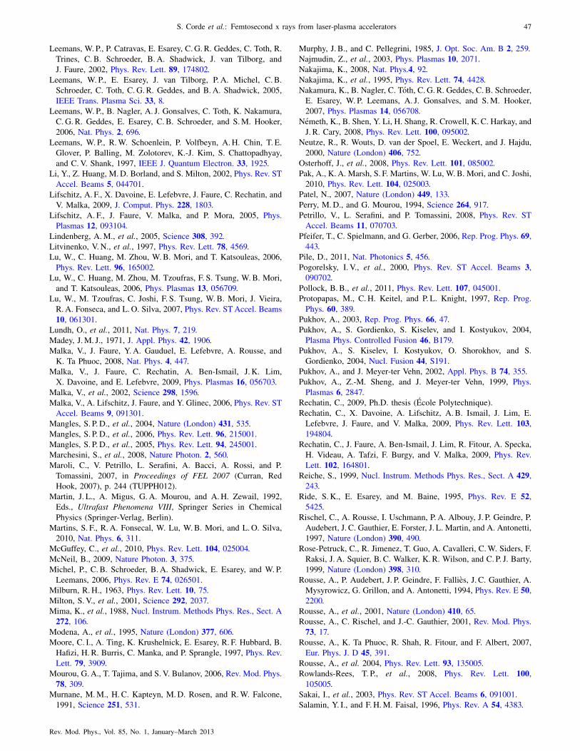
Leemans, W. P., P. Catravas, E. Esarey, C. G. R. Geddes, C. Toth, R.
Trines, C. B. Schroeder, B. A. Shadwick, J. van Tilborg, and
J. Faure, 2002, Phys. Rev. Lett. 89, 174802.
Leemans, W. P., E. Esarey, J. van Tilborg, P. A. Michel, C. B.
Schroeder, C. Toth, C. G. R. Geddes, and B.A. Shadwick, 2005,
IEEE Trans. Plasma Sci. 33, 8.
Leemans, W. P., B. Nagler, A. J. Gonsalves, C. Toth, K. Nakamura,
C. G. R. Geddes, E. Esarey, C. B. Schroeder, and S.M. Hooker,
2006, Nat. Phys. 2, 696.
Leemans, W. P., R.W. Schoenlein, P. Volfbeyn, A.H. Chin, T. E.
Glover, P. Balling, M. Zolotorev, K.-J. Kim, S. Chattopadhyay,
and C. V. Shank, 1997, IEEE J. Quantum Electron. 33, 1925.
Li, Y., Z. Huang, M.D. Borland, and S. Milton, 2002, Phys. Rev. ST
Accel. Beams 5, 044701.
Lifschitz, A. F., X. Davoine, E. Lefebvre, J. Faure, C. Rechatin, and
V. Malka, 2009, J. Comput. Phys. 228, 1803.
Lifschitz, A. F., J. Faure, V. Malka, and P. Mora, 2005, Phys.
Plasmas 12, 093104.
Lindenberg, A.M., et al., 2005, Science 308, 392.
Litvinenko, V. N., et al., 1997, Phys. Rev. Lett. 78, 4569.
Lu, W., C. Huang, M. Zhou, W.B. Mori, and T. Katsouleas, 2006,
Phys. Rev. Lett. 96, 165002.
Lu, W., C. Huang, M. Zhou, M. Tzoufras, F. S. Tsung, W.B. Mori,
and T. Katsouleas, 2006, Phys. Plasmas 13, 056709.
Lu, W., M. Tzoufras, C. Joshi, F. S. Tsung, W.B. Mori, J. Vieira,
R. A. Fonseca, and L.O. Silva, 2007, Phys. Rev. STAccel. Beams
10, 061301.
Lundh, O., et al., 2011, Nat. Phys. 7, 219.
Madey, J.M. J., 1971, J. Appl. Phys. 42, 1906.
Malka, V., J. Faure, Y. A. Gauduel, E. Lefebvre, A. Rousse, and
K. Ta Phuoc, 2008, Nat. Phys. 4, 447.
Malka, V., J. Faure, C. Rechatin, A. Ben-Ismail, J. K. Lim,
X. Davoine, and E. Lefebvre, 2009, Phys. Plasmas 16, 056703.
Malka, V., et al., 2002, Science 298, 1596.
Malka, V., A. Lifschitz, J. Faure, and Y. Glinec, 2006, Phys. Rev. ST
Accel. Beams 9, 091301.
Mangles, S. P. D., et al., 2004, Nature (London) 431, 535.
Mangles, S. P. D., et al., 2006, Phys. Rev. Lett. 96, 215001.
Mangles, S. P. D., et al., 2005, Phys. Rev. Lett. 94, 245001.
Marchesini, S., et al., 2008, Nature Photon. 2, 560.
Maroli, C., V. Petrillo, L. Serafini, A. Bacci, A. Rossi, and P.
Tomassini, 2007, in Proceedings of FEL 2007 (Curran, Red
Hook, 2007), p. 244 (TUPPH012).
Martin, J. L., A. Migus, G. A. Mourou, and A.H. Zewail, 1992,
Eds., Ultrafast Phenomena VIII, Springer Series in Chemical
Physics (Springer-Verlag, Berlin).
Martins, S. F., R. A. Fonsecal, W. Lu, W.B. Mori, and L.O. Silva,
2010, Nat. Phys. 6, 311.
McGuffey, C., et al., 2010, Phys. Rev. Lett. 104, 025004.
McNeil, B., 2009, Nature Photon. 3, 375.
Michel, P., C. B. Schroeder, B. A. Shadwick, E. Esarey, and W. P.
Leemans, 2006, Phys. Rev. E 74, 026501.
Milburn, R. H., 1963, Phys. Rev. Lett. 10, 75.
Milton, S. V., et al., 2001, Science 292, 2037.
Mima, K., et al., 1988, Nucl. Instrum. Methods Phys. Res., Sect. A
272, 106.
Modena, A., et al., 1995, Nature (London) 377, 606.
Moore, C. I., A. Ting, K. Krushelnick, E. Esarey, R. F. Hubbard, B.
Hafizi, H. R. Burris, C. Manka, and P. Sprangle, 1997, Phys. Rev.
Lett. 79, 3909.
Mourou, G. A., T. Tajima, and S. V. Bulanov, 2006, Rev. Mod. Phys.
78, 309.
Murnane, M.M., H. C. Kapteyn, M.D. Rosen, and R.W. Falcone,
1991, Science 251, 531.
Murphy, J. B., and C. Pellegrini, 1985, J. Opt. Soc. Am. B 2, 259.
Najmudin, Z., et al., 2003, Phys. Plasmas 10, 2071.
Nakajima, K., 2008, Nat. Phys.4, 92.
Nakajima, K., et al., 1995, Phys. Rev. Lett. 74, 4428.
Nakamura, K., B. Nagler, C. Toth, C. G. R. Geddes, C. B. Schroeder,
E. Esarey, W. P. Leemans, A. J. Gonsalves, and S.M. Hooker,
2007, Phys. Plasmas 14, 056708.
Nemeth, K., B. Shen, Y. Li, H. Shang, R. Crowell, K. C. Harkay, and
J. R. Cary, 2008, Phys. Rev. Lett. 100, 095002.
Neutze, R., R. Wouts, D. van der Spoel, E. Weckert, and J. Hajdu,
2000, Nature (London) 406, 752.
Osterhoff, J., et al., 2008, Phys. Rev. Lett. 101, 085002.
Pak, A., K. A. Marsh, S. F. Martins, W. Lu, W.B. Mori, and C. Joshi,
2010, Phys. Rev. Lett. 104, 025003.
Patel, N., 2007, Nature (London) 449, 133.
Perry, M.D., and G. Mourou, 1994, Science 264, 917.
Petrillo, V., L. Serafini, and P. Tomassini, 2008, Phys. Rev. ST
Accel. Beams 11, 070703.
Pfeifer, T., C. Spielmann, and G. Gerber, 2006, Rep. Prog. Phys. 69,
443.
Pile, D., 2011, Nat. Photonics 5, 456.
Pogorelsky, I. V., et al., 2000, Phys. Rev. ST Accel. Beams 3,
090702.
Pollock, B. B., et al., 2011, Phys. Rev. Lett. 107, 045001.
Protopapas, M., C. H. Keitel, and P. L. Knight, 1997, Rep. Prog.
Phys. 60, 389.
Pukhov, A., 2003, Rep. Prog. Phys. 66, 47.
Pukhov, A., S. Gordienko, S. Kiselev, and I. Kostyukov, 2004,
Plasma Phys. Controlled Fusion 46, B179.
Pukhov, A., S. Kiselev, I. Kostyukov, O. Shorokhov, and S.
Gordienko, 2004, Nucl. Fusion 44, S191.
Pukhov, A., and J. Meyer-ter Vehn, 2002, Appl. Phys. B 74, 355.
Pukhov, A., Z.-M. Sheng, and J. Meyer-ter Vehn, 1999, Phys.
Plasmas 6, 2847.
Rechatin, C., 2009, Ph.D. thesis (Ecole Polytechnique).
Rechatin, C., X. Davoine, A. Lifschitz, A. B. Ismail, J. Lim, E.
Lefebvre, J. Faure, and V. Malka, 2009, Phys. Rev. Lett. 103,
194804.
Rechatin, C., J. Faure, A. Ben-Ismail, J. Lim, R. Fitour, A. Specka,
H. Videau, A. Tafzi, F. Burgy, and V. Malka, 2009, Phys. Rev.
Lett. 102, 164801.
Reiche, S., 1999, Nucl. Instrum. Methods Phys. Res., Sect. A 429,
243.
Ride, S. K., E. Esarey, and M. Baine, 1995, Phys. Rev. E 52,
5425.
Rischel, C., A. Rousse, I. Uschmann, P. A. Albouy, J. P. Geindre, P.
Audebert, J. C. Gauthier, E. Forster, J. L. Martin, and A. Antonetti,
1997, Nature (London) 390, 490.
Rose-Petruck, C., R. Jimenez, T. Guo, A. Cavalleri, C.W. Siders, F.
Raksi, J. A. Squier, B. C. Walker, K. R. Wilson, and C. P. J. Barty,
1999, Nature (London) 398, 310.
Rousse, A., P. Audebert, J. P. Geindre, F. Fallies, J. C. Gauthier, A.
Mysyrowicz, G. Grillon, and A. Antonetti, 1994, Phys. Rev. E 50,
2200.
Rousse, A., et al., 2001, Nature (London) 410, 65.
Rousse, A., C. Rischel, and J.-C. Gauthier, 2001, Rev. Mod. Phys.
73, 17.
Rousse, A., K. Ta Phuoc, R. Shah, R. Fitour, and F. Albert, 2007,
Eur. Phys. J. D 45, 391.
Rousse, A., et al. 2004, Phys. Rev. Lett. 93, 135005.
Rowlands-Rees, T. P., et al., 2008, Phys. Rev. Lett. 100,
105005.
Sakai, I., et al., 2003, Phys. Rev. ST Accel. Beams 6, 091001.
Salamin, Y. I., and F.H.M. Faisal, 1996, Phys. Rev. A 54, 4383.
S. Corde et al.: Femtosecond x rays from laser-plasma accelerators 47
Rev. Mod. Phys., Vol. 85, No. 1, January–March 2013

Saldin, E., E. Schneidmiller, and M. Yurkov, 1998, Opt. Commun.
148, 383.
Saldin, E. L., E. A. Schneidmiller, and M.V. Yurkov, 2000, The
Physics of Free Electron Lasers (Springer-Verlag, Berlin).
Sandorfi, A.M., M. J. Levine, C. E. Thorn, G. Giordano, G. Matone,
and C. Schaerf, 1983, IEEE Trans. Nucl. Sci. 30, 3083.
Santala, M. I. K., Z. Najmudin, E. L. Clark, M. Tatarakis, K.
Krushelnick, A. E. Dangor, V. Malka, J. Faure, R. Allott, and
R. J. Clarke, 2001, Phys. Rev. Lett. 86, 1227.
Sarachik, E. S., and G. T. Schappert, 1970, Phys. Rev. D 1, 2738.
Schlenvoigt, H. P., et al., 2008a, Nat. Phys. 4, 130.
Schlenvoigt, H. P., et al., 2008b, IEEE Trans. Plasma Sci. 36, 1773.
Schoenlein, R.W., S. Chattopadhyay, H.H.W. Chong, T. E. Glover,
P. A. Heimann, C.V. Shank, A. A. Zholents, and M. S. Zolotorev,
2000, Science 287, 2237.
Schoenlein, R.W., W. P. Leemans, A.H. Chin, P. Volfbeyn, T. E.
Glover, P. Balling, M. Zolotorev, K. J. Kim, S. Chattopadhyay, and
C.V. Shank, 1996, Science 274, 236.
Schwoerer, H., B. Liesfeld, H.-P. Schlenvoigt, K.-U. Amthor, and
R. Sauerbrey, 2006, Phys. Rev. Lett. 96, 014802.
Service, R. F., 2002, Science 298, 1356.
Shah, R. C., F. Albert, K. Ta Phuoc, O. Shevchenko, D. Boschetto,
A. Pukhov, S. Kiselev, F. Burgy, J.-P. Rousseau, and A. Rousse,
2006, Phys. Rev. E 74, 045401.
Shen, B. F., W. Yu, G. H. Zeng, and Z. Z. Xu, 1997, Opt. Commun.
136, 239.
Siders, C.W., A. Cavalleri, K. Sokolowski-Tinten, C. Toth, T. Guo,
M. Kammler, M.H. von Hoegen, K. R. Wilson, D. von der Linde,
and C. P. J. Barty, 1999, Science 286, 1340.
Sokolowski-Tinten, K., et al., 2003, Nature (London) 422, 287.
Sokolowski-Tinten, K., C. Blome, C. Dietrich, A. Tarasevitch, M.
Horn von Hoegen, D. von der Linde, A. Cavalleri, J. Squier, and
M. Kammler, 2001, Phys. Rev. Lett. 87, 225701.
Sprangle, P., A. Ting, E. Esarey, and A. Fisher, 1992, J. Appl. Phys.
72, 5032.
Strickland, D., and G. Mourou, 1985, Opt. Commun. 56, 219.
Suk, H., N. Barov, J. B. Rosenzweig, and E. Esarey, 2001, Phys.
Rev. Lett. 86, 1011.
Tajima, T., and J.M. Dawson, 1979, Phys. Rev. Lett. 43, 267.
Ta Phuoc, K., F. Burgy, J.-P. Rousseau, V. Malka, A. Rousse, R.
Shah, D. Umstadter, A. Pukhov, and S. Kiselev, 2005, Phys.
Plasmas 12, 023101.
Ta Phuoc, K., F. Burgy, J.-P. Rousseau, and A. Rousse, 2005, Eur.
Phys. J. D 33, 301.
Ta Phuoc, K., S. Corde, R. Fitour, R. Shah, F. Albert, J.-P. Rousseau,
F. Burgy, A. Rousse, V. Seredov, and A. Pukhov, 2008, Phys.
Plasmas 15, 073106.
Ta Phuoc, K., S. Corde, R. Shah, F. Albert, R. Fitour, J. P. Rousseau,
F. Burgy, B. Mercier, and A. Rousse, 2006, Phys. Rev. Lett. 97,
225002.
Ta Phuoc, K., S. Corde, C. Thaury, V. Malka, A. Tafzi, J.-P. Goddet,
R.C. Shah, S. Sebban, and A. Rousse, 2012, Nature Photon. 6, 308.
Ta Phuoc, K., E. Esarey, V. Leurent, E. Cormier-Michel, C. G. R.
Geddes, C. B. Schroeder, A. Rousse, and W. P. Leemans, 2008,
Phys. Plasmas 15, 063102.
Ta Phuoc, K., A. Rousse, M. Pittman, J. P. Rousseau, V. Malka, S.
Fritzler, D. Umstadter, and D. Hulin, 2003, Phys. Rev. Lett. 91,
195001.
Ta Phuoc, K., et al., 2007, Phys. Plasmas 14, 080701.
Ta Phuoc, K., et al., 2003, J. Opt. Soc. Am. B 20, 221.
Tarasevitch, A., A. Orisch, D. von der Linde, P. Balcou, G. Rey, J.-P.
Chambaret, U. Teubner, D. Klopfel, and W. Theobald, 2000, Phys.
Rev. A 62, 023816.
Telnov, V., 1997, Phys. Rev. Lett. 78, 4757.
Teubner, U., and P. Gibbon, 2009, Rev. Mod. Phys. 81, 445.
Thaury, C., et al., 2007, Nat. Phys. 3, 424.
Thomas, A. G. R., 2010, Phys. Plasmas 17, 056708.
Thomas, A. G. R., et al., 2009, Plasma Phys. Controlled Fusion 51,
024010.
Thomas, A. G. R., et al., 2007, Phys. Rev. Lett. 98, 095004.
Tian, Y., W. Yu, F. He, H. Xu, V. Senecha, D. Deng, Y. Wang, R. Li,
and Z. Xu, 2006, Phys. Plasmas 13, 123106.
Tiedtke, K., et al., 2009, New J. Phys. 11, 023029.
Ting, A., R. Fischer, A. Fisher, K. Evans, R. Burris, J. Krall,
E. Esarey, and P. Sprangle, 1995, J. Appl. Phys. 78, 575.
Ting, A., C. I. Moore, K. Krushelnick, C. Manka, E. Esarey,
P. Sprangle, R. Hubbard, H. R. Burris, R. Fischer, and M.
Baine, 1997, Phys. Plasmas 4, 1889.
Tomassini, P., A. Giulietti, D. Giulietti, and L. Gizzi, 2005, Appl.
Phys. B 80, 419.
Tsakiris, G. D., C. Gahn, and V.K. Tripathi, 2000, Phys. Plasmas 7,
3017.
Tsung, F. S., W. Lu, M. Tzoufras, W. B. Mori, C. Joshi, J.M. Vieira,
L. O. Silva, and R.A. Fonseca, 2006, Phys. Plasmas 13, 056708.
Tsung, F. S., R. Narang, W.B. Mori, C. Joshi, R. A. Fonseca, and
L.O. Silva, 2004, Phys. Rev. Lett. 93, 185002.
Tzoufras, M., W. Lu, F. S. Tsung, C. Huang, W.B. Mori,
T. Katsouleas, J. Vieira, R. A. Fonseca, and L. O. Silva, 2008,
Phys. Rev. Lett. 101, 145002.
Tzoufras, M., W. Lu, F. S. Tsung, C. Huang, W.B. Mori,
T. Katsouleas, J. Vieira, R. A. Fonseca, and L. O. Silva, 2009,
Phys. Plasmas 16, 056705.
Ueshima, Y., Y. Kishimoto, A. Sasaki, and T. Tajima, 1999, Laser
Part. Beams 17, 45.
Umstadter, D., 2003, J. Phys. D 36, R151.
Umstadter, D., S. Y. Chen, A. Maksimchuk, G. Mourou, and
R. Wagner, 1996, Science 273, 472.
Umstadter, D., J.K.Kim, and E.Dodd, 1996, Phys. Rev. Lett. 76, 2073.
Vachaspati, 1962, Phys. Rev. 128, 664.
van Tilborg, J., C. B. Schroeder, C. V. Filip, C. Toth, C. G. R.
Geddes, G. Fubiani, R. Huber, R. A. Kaindl, E. Esarey, and
W. P. Leemans, 2006, Phys. Rev. Lett. 96, 014801.
Vieira, J., S. F. Martins, V. B. Pathak, R. A. Fonseca, W. B. Mori, and
L.O. Silva, 2011, Phys. Rev. Lett. 106, 225001.
Wagner, R., S.-Y. Chen, A. Maksimchuk, and D. Umstadter, 1997,
Phys. Rev. Lett. 78, 3125.
Wang, S., et al., 2002, Phys. Rev. Lett. 88, 135004.
Whittum, D.H., 1992, Phys. Fluids B 4, 730.
Whittum, D. H., A.M. Sessler, and J.M. Dawson 1990, Phys. Rev.
Lett. 64, 2511.
Wiedemann, H., 2007a, Particle Accelerator Physics (Springer-
Verlag, Berlin), 3rd ed.
Wiedemann, H., 2007b, Particle Accelerator Physics (Springer-
Verlag, Berlin), 3rd ed., Chap. 24.
Wu, H.-C., B.-S. Xie, M.-P. Liu, X.-R. Hong, S. Zhang, and M.Y.
Yu, 2009, Phys. Plasmas 16, 073108.
Xie, B.-S., H.-C. Wu, H. Wang, N.-Y. Wang, and M.Y. Yu, 2007,
Phys. Plasmas 14, 073103.
Xie, M., 2000, Nucl. Instrum. Methods Phys. Res., Sect. A 445, 59.
Yang, J., M. Washio, A. Endo, and T. Hori, 1999, Nucl. Instrum.
Methods Phys. Res., Sect. A 428, 556.
Yorozu, M., J. Yang, Y. Okada, T. Yanagida, F. Sakai, S. Ito, and A.
Endo, 2003, Appl. Phys. B 76, 293.
Yorozu, M., J. F. Yang, Y. Okada, T. Yanagida, F. Sakai, and A.
Endo, 2001, Jpn. J. Appl. Phys. 40, 4228.
Zewail, A.H., 1997, in Femtochemistry and Femtobiology: Ultrafast
Reaction Dynamics at Atomic-Scale Resolution, edited by V.
Sundstrom (World Scientific, Singapore).
48 S. Corde et al.: Femtosecond x rays from laser-plasma accelerators
Rev. Mod. Phys., Vol. 85, No. 1, January–March 2013