femur omeg a3 system 95˚ supracondylar plate€¦ · omega3 supracondylar plate with lag screw. 10...
TRANSCRIPT

Omega3 System95˚ Supracondylar Plate
Operative Technique• Distal Femur• Axially Stable Locking Option
Femur Fractures
Femur

2
Contents
Introduction, Potential Features & Benefits 3Relative Indications & Contraindications 5Patient Positioning 6Combination Reamer Assembly Instructions 7Instrument Assembly 8
Operative Technique
Incision, Exposure, and Reduction of the Fracture 9Guide Pin Insertion 10Guide Pin Measurement 12Lag Screw Reaming 13Lag Screw Insertion 14Supracondylar Plate Attachment 16Supracondylar Plate Fixation with Standard Cortical Screws 17Supracondylar Plate Fixation with Axial Stable Locking Screws 19Extraction of Locking Inserts 24Fracture Compression 25Closing the wound 25Implant Removal 26
Ordering Information
Instruments for Basic Lag Screw Set 27Locking Instruments 29Optional Instruments 30Omega3 Supracondylar Plates 31Lag Screws 31Compression Screw 31Cortical Screws Ø4.5mm 32Locking Screws Ø5.0mm and Locking Insert 32Cancellous Screws Ø6.5mm 33Asnis™ III Screws Ø6.5mm 33
This publication sets forth detailed recommended procedures for using Stryker Trauma devices and instruments. It offers guidance that you should heed,but, as with any such technical guide, each surgeon must consider the particularneeds of each patient and make appropriate adjustments when and as required. A workshop training is recommended prior to first surgery.
Note: All bone screws referenced in this material here are not approved forscrew attachment or fixation to the posterior elements (pedicles) of the cervical, thoracic or lumbar spine.

3
Potential Features & Benefits
IntroductionThe 95° plate angle design of the Omega3 Supracondylar Plate contours to the anatomy of the distal femur including the flare of the lateral femoralcondyle. This assures more precise component fit and function with enhancedcontouring to bone.
Potential Features & Benefits
• Super-strong, cold-forged 1.4441stainless steel alloy provideshigh resistance to pitting andcorrosion and excellentresistance to bending stresses.
• Supracondylar plates are available insterile packaging for customer convenience.
• Available in five lengths: accordingto the number of holes: 6, 8, 10,12 and 14 hole plates(excluding the lag screw hole). All lengths available in keyed andkeyless barrels.
• Instrumentation and streamlinedtechnique enhance surgicalefficiency.
95˚
95˚
Omega3 Supracondylar Plate
• In addition to 4.5mm CorticalScrews, all sideplate holes accept6.5mm Cancellous Screws or AsnisIII 6.5mm Cannulated Screws foradditional stabilization.
• Stable Fixation - On demand axialstable fixation with 5.0mm LockingInserts and Locking Screws orstandard screw fixation.
• Axial Stable, 14° Diverging Locking -Monoaxial stable fixation incombination with diverging LockingScrew configuration results inincreased stability.
• Super-strong, cold-forged 1.4441stainless steel alloy provideshigh resistance to pitting andcorrosion and excellentresistance to bending stresses.

4
Lag ScrewThe Omega Ø13mm Lag Screw isdesigned for maximum performance ina variety of applications and conditions.
The leading edge cutting thread of the standard lag screw engages quickly,with or without tapping, and providestactile control during final positioningand seating.
The Super Lag Screw incorporates a 15mm diameter thread for use inosteoporotic bone and revision cases.
The Anti-rotational design provides the security and versatility of a keyed system.
The Lag Screw is intended for use withboth the Omega3 Compression HipPlate and the 95° Supracondylar Plate.
CompressionScrewThe Omega3 Compression Screwstabilizes the Lag Screw, while providingfor an extra measure of compression afterimpaction.
Allows for up to 10mm of compression,when required.
Beveled tip provides for quick centeringand thread engagement.
Potential Features & Benefits, continued

5
The surgeon’s education, training andprofessional judgement must be relied upon to choose the mostappropriate device and treatment. Conditions presenting an increased risk of failure include:
• Any active or suspected latentinfection or marked localinflammation in or about the affected area.
• Compromised vascularity that wouldinhibit adequate blood supply to thefracture or the operative site.
• Bone stock compromised by disease, infection or priorimplantation that can not provideadequate support and/or fixation of the devices.
• Material sensitivity, documented or suspected.
• Significant Obesity. An obese patient can produce loads on theimplant that can lead to failure of the fixation of the device or to failureof the device itself.
Relative IndicationsThe Omega3 Supracondylar Plate is indicated for fractures of the distal femur which may include:
The following conditions should exist:
• A distal portion of the medialcondyle should be intact for the lagscrew to gain adequate purchase.
The Omega3 Supracondylar Plate isalso indicated for osteotomies of theproximal and the distal femur.
• Intercondylar Fractures • Supracondylar Fractures • Unicondylar Fractures
Relative Indications & Contraindications
• Patients having inadequate tissuecoverage over the operative site.
• Implant utilization that wouldinterfere with anatomical structuresor physiological performance.
• Any mental or neuromusculardisorder which would create anunacceptable risk of fixation failureor complications in postoperativecare.
• Other medical or surgical conditionswhich would preclude the potentialbenefit of surgery.
Detailed information is included inthe instructions for use being attachedto and shipped with every implant.
See package insert for a complete list of potential adverse effects andcontraindications. The surgeon mustdiscuss all relevant risks, including the finite lifetime of the device, withthe patient, when necessary.
Caution: Bone Screws are not intendedfor screw attachment or fixation to theposterior elements (pedicles) of thecervical, thoracic or lumbar spine.
Relative Contraindications

6
Operative Technique
Patient PositioningThe Patient is placed in the supineposition on a standard operating tablewith a support under the femur onwhich the operation is performed.Access to the distal femur with the C-arm in medial/ lateral andanterior/posterior planes is verifiedprior to surgery.

7
Operative Technique
Combination Reamer Drill
Step 2
Align the flat side of the Barrel Reamerto the flat side of the CombinationReamer Drill, and engage the BarrelReamer over the coupling end of theCombination Reamer Drill.
Note: Flat sides must be aligned.
Step 3
Slide the Barrel Reamer until the stop has been adjusted to the correctmeasurement behind the barrel. Lock the Barrel Reamer by turning the Stop Sleeve counter-clockwiseuntil the Barrel Reamer is fixed to theCombination Reamer Drill.
Barrel Reamer Assembly
Instrument AssemblyCombination Reamer Assembly:
Barrel Reamer, Short
Flat side
Step 1
Select and assemble the Barrel Reamer.Note: Choose the corresponding
Barrel Reamer, i.e. Short Barrelfor the Omega3 SupracondylarPlate. The choice of Barrellength might be different whenplacing an Omega3 Hip Plate. In this case, please refer to thecorresponding operativetechnique guide.When assembling, the StopSleeve must be threaded until a mechanical stop is felt.

8
Operative Technique
Instrument Assembly, continued
Large Elastosil T-Handle
(REF 704020)
Large Elastosil T-Handle
(REF 704020)
Lag Screw Tap Sleeve
(REF 704008)
Lag Screw Inserter Sleeve
(REF 704022)
Lag ScrewInserter
(REF 704021)
Lag ScrewAdapter
(Inner Part) (1)
Lag ScrewAdapter
(Outer part) (2)
Lag Screw (3)
Lag Screw Tap Assembly:
Lag Screw Adapter Assembly:
Push the quick coupling sleeve on theT-Handle and insert the Lag Screw Tapfitting into the coupling.
Assemble the Lag Screw Tap Sleeve tothe Lag Screw Tap by aligning the flatsides of the Tap to the flat sides in theTap Sleeve.
The appropriate Lag Screw is preparedby placing the inner part of the Lag Screw Adapter (1) through the
outer part (2), and threading it intothe Lag Screw (3).
Lag Screw Inserter Assembly:Attach the Lag Screw Inserter to the T-Handle .
Slide the Lag Screw Inserter Sleeveover the Lag Screw Inserter.
Lag Screw Tap
(REF 704007)
Lag Screw Adapter Assembly
(REF 704009)
Assemble the T-Handle to the Lag Screw Inserter as described in instruction above.
The Connecting Bolt is insertedthrough the Large Elastosil T-handleand threaded in to the Lag Screw.
Lag Screw Removal Assembly:
Large ElastosilT-Handle
(REF 704020)
Lag Screw Inserter
(REF 704021)
Lag Screw Connecting Bolt
(REF 704004)

9
Incision, Exposure & Reduction of the Fracture
IncisionExpose the fracture through ananterolateral or lateral approach in line with the greater trochanter and the lateral femoral condyle. If a lateralapproach is used, care must be taken to avoid excessive use of a levering orself-retaining retractor to retract thequadriceps musculature. This type ofretraction can result in excessivemedial soft tissue stripping. If this approach is utilized, retractionshould be achieved by “lifting” themuscle up to view lateral structures.Retraction on the medial side shouldbe limited as much as possible.
The anterolateral approach allowsmore controlled soft tissue dissectionand retraction. The incision is started15cm-20cm proximal to the patellaand continued distally to the lateralborder of the patella. The length of the incision is, of course,determined by the extent of thefracture (Fig. 1). Open the intervalbetween the vastus lateralis and therectus femoris to expose the vastusintermedius. Longitudinally incise thefibers of the vastus intermedius overthe anterior aspect of the femur.Extend the dissection subperiosteallyaround the bone.
Fig. 1 Fig. 2 Fig. 3
Operative Technique
LateralApproach
AnterolateralApproach
FractureReductionThe fracture should be reduced by direct vision. Intra-articularfractures may be stabilized temporarilywith intra-fragmentary screws or k-wires (Fig. 2 & 3). Inspect thesupracondylar portion of the fracturefor comminution and assess thepossibility of requiring bone graft.Reduce the fracture and stabilize itwith bone clamps.
Avoid any unnecessary medialdissection.
Technical Note: A three-part “T” fracture is reduced by conversionto a two-part fracture by stabilizationwith Asnis III Cannulated Screws (Fig. 3) and then reduced to thefemoral shaft, utilizing theSupracondylar Plate and Screws.
Note: Make sure that the Asnis IIICannulated Screws do notinterfere with the later appliedOmega3 Supracondylar Platewith Lag Screw.
10
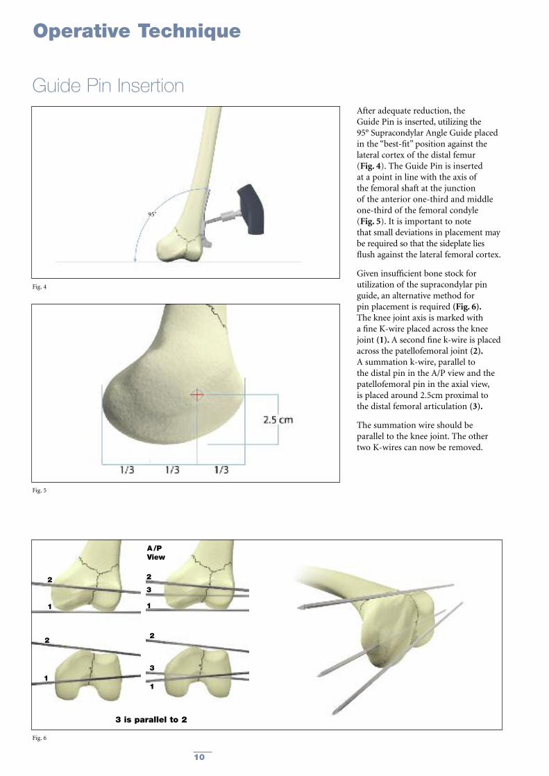
After adequate reduction, the Guide Pin is inserted, utilizing the 95° Supracondylar Angle Guide placedin the “best-fit” position against thelateral cortex of the distal femur (Fig. 4). The Guide Pin is insertedat a point in line with the axis of the femoral shaft at the junction of the anterior one-third and middleone-third of the femoral condyle (Fig. 5). It is important to note that small deviations in placement may be required so that the sideplate liesflush against the lateral femoral cortex.
Given insufficient bone stock forutilization of the supracondylar pinguide, an alternative method for pin placement is required (Fig. 6).The knee joint axis is marked with a fine K-wire placed across the kneejoint (1). A second fine k-wire is placedacross the patellofemoral joint (2).A summation k-wire, parallel to the distal pin in the A/P view and thepatellofemoral pin in the axial view, is placed around 2.5cm proximal to the distal femoral articulation (3).
The summation wire should be parallel to the knee joint. The othertwo K-wires can now be removed.
Fig. 4
Fig. 5
Fig. 6
Operative Technique
Guide Pin Insertion
2
1
2
1
2
3
1
3 is parallel to 2
2
A/PView
3
1
95˚

11
Note: Placement of the Guide Pindetermines the final placementof the Lag Screw. If the GuidePin is improperly placed, a varus/valgus or rotationalmalalignment of the fracturefragments can result.
Using image intensification, drill theGuide Pin into the condyle. The Guide Pin should be advanceduntil it abuts the subcortical bone ofthe medial femoral condyle. Because of the shape of the distalfemur, the pin may not appear to crossthe medial cortex when viewed underfluoroscopy (Fig. 7).
Fig. 7
Guide Pin Insertion, continued
Operative Technique

12
Use the Lag Screw Depth Gauge tomeasure the length of the pin in thebone by sliding the Depth Gauge overthe Guide Pin and pushing the gaugeagainst the lateral cortex (ensure thatthere is no soft tissue between theDepth Gauge and the bone). The reading, minus 10mm, determinesthe settings for the CombinationReamer and Tap, and indicates thelength of the Lag Screw to be used.(Fig. 8).If the Depth Gauge reading is not a 5mm increment, set the remainder atthe next shortest setting minus 10mm.
Operative Technique
Guide Pin Measurement
Example :
• Direct reading depth gaugemeasurement: 90mm
• Reamer depth Setting: 80mm
• Tapping depth (if required): 80mm
• Lag Screw Length selected: 80mm
Fig. 8

13
Set and lock the short CombinationReamer to the predetermined reading(10mm less than the Guide Pinmeasurement).
Ream until the Combination Reamerstops itself at the lateral cortex (Fig. 9a).
Operative Technique
Lag Screw Reaming
Fig. 9a
When treating supracondylarfractures, use the lag screwCombination Reamer with the shortbarrel only. This will ensure that thereamer for the barrel position is thesame length as the barrel for theSupracondylar Plate. The Combination Reamer is insertedover the Guide Pin, and the channel isreamed until the flared section of thebarrel reamer has entered the lateralfemoral cortex. The reamer will advance no further at this point.The reaming should be verified usingfluoroscopy.
The Combination Reamer is designed to ream not only for the lag screw andshort barrel of the plate, but also theflair of the barrel plate junction.
Should the guide pin inadvertentlywithdraw with the reamer, insert theGuide Pin Replacement Instrument inthe reamed hole and reinsert theGuide Pin through the central hole (Fig. 9b).
Fig. 9b

14
Operative Technique
Lag Screw Insertion
Depth indicator rings measure desired compression, which is applied later in a second step with the insertion of the Compression Screw.
Depth indicator rings
No Compression 5mm Compression 10mm Compression
The Lag Screw Inserter Sleeve on the Lag Screw Inserter Assembly isadvanced into the pre-reamed hole,and the Lag Screw is advanced into the prepared channel.
Depth of insertion of the Lag Screw is determined by observing the 135°-depth-indicator-ring on theinserter. The Lag Screw is inserteduntil the first (0mm) mark is reached. (Fig. 11).
This is confirmed by fluoroscopy. This gives the surgeon 10mm ofavailable compression.
Select a Lag Screw of the appropriatelength and assemble it to the Lag Screw Adapter.(For assembling instructions see Page 8).
Now place the Lag Screw AdapterAssembly into the Lag Screw Inserter,and direct it toward the bone over theGuide Pin (Fig. 10). (For assembling instructions see Page 8).
Fig. 10
Fig. 11

15
Operative Technique
Lag Screw Insertion, continuedThe Large T-Handle of the insertionwrench is aligned with the long axisof the femur. This positions the flats of the Lag Screw to ensure properalignment with the SupracondylarPlate (Fig. 12).
Upon completion of the Lag Screwinsertion, the Lag Screw InserterAssembly is removed, leaving the Lag Screw with Lag Screw Adapter in place (Fig. 13).
Fig. 13
Fig. 12

16
Operative Technique
Supracondylar Plate Attachment
The Plate Impactor should be used tofully seat the Supracondylar Plate (Fig. 15). Unscrew the Lag ScrewAdapter and remove it. Then, removethe 2.8mm Guide Pin.
Note: All Guide Pins are “Single-use”products and therefore must bediscarded at the end of thesurgical procedure.
Fig. 15
The selected 6-, 8-, 10-, 12-, or 14-holeSupracondylar Plate is now placed overthe Lag Screw Adapter, and advancedonto the Lag Screw (Fig. 14).
Note: If the Supracondylar Plate doesnot line up with the shaft of the femur, the Lag ScrewInserter can be placed onceagain over the Lag ScrewAdapter and plate alignmentcan be fine-tuned.Alternatively, the plate can be placed over the Lag Screw;by rotating the plate, finalposition of the Lag Screw can be achieved.
Fig. 14

17
Operative Technique
Supracondylar Plate Fixation with Standard Cortical ScrewsUsing standard screw insertion technique,fix the Omega3 Supracondylar Plate tothe femoral shaft beginning at theproximal end of the plate.
This will ensure that the remainingintermediary screw holes will entermidaxially across the femur, thus gaining bicortical fixation.
Drill the bone screw holes using the3.2mm Drill Bit through the 3.2mmNeutral Drill Sleeve with the green ringassembled to the Drill Guide Handle(Fig. 16).
Determine appropriate Cortical Screwlength using the Depth GaugeAssembly (Fig. 17).
Note: If necessary, it is possible toobtain 1mm compression in the axis of the SupracondylarPlate by using the 3.2mmCompression Drill Sleeve with the yellow ring.
Fig. 16
Fig. 17
Fig. 18
Insert the 4.5mm Cortical Screws using the 3.5mm Hex Screwdriver(Fig. 18).
18
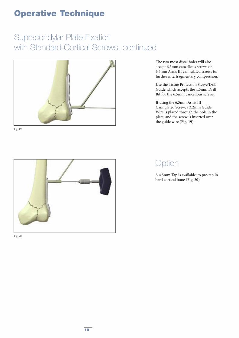
A 4.5mm Tap is available, to pre-tap inhard cortical bone (Fig. 20).
The two most distal holes will alsoaccept 6.5mm cancellous screws or6.5mm Asnis III cannulated screws forfurther interfragmentary compression.
Use the Tissue Protection Sleeve/DrillGuide which accepts the 4.5mm DrillBit for the 6.5mm cancellous screws.
If using the 6.5mm Asnis IIICannulated Screw, a 3.2mm GuideWire is placed through the hole in theplate, and the screw is inserted overthe guide wire (Fig. 19).
Option
Fig. 20
Fig. 19
Operative Technique
Supracondylar Plate Fixation with Standard Cortical Screws, continued

19
The shaft of the Supracondylar Plate is designed to accept Ø4.5mmstandard Cortical Screws for neutral or compression plate attachment to the femoral bone according to standard technique described in this operative technique (page 17).
Alternatively, Ø5.0mm Locking Inserts and Ø5.0mm Locking Screws may be preferred for axial stable locking in patients with poor bone quality or to perform minimal invasive surgery with a shorter plate.
Locking Inserts and Screws may beused in conjunction with StandardCortical Screws on the sameSupracondylar plate.
However, Standard Cortical Screwsmay not be used in the Locking Inserts.Also it is mandatory to utilize theinstrumentation designed specificallyfor the Locking Inserts and Screws.
Supracondylar Plate Fixationwith Axial Stable Locking Screws
Step 1 Locking Insert Placement:Option 1: Placement of the Locking Insert before Implantation of the Supracondylar Plate
Before you place the SupracondylarPlate over the Lag Screw onto the bone, thread a 5.0mm LockingInsert to the Inserter Instrument and push the Locking Insert into the chosen shaft hole of the Omega3Supracondylar Plate (Fig. 21).
Note: The two first, most distal holes of the plate does not accept a Locking Insert (A). A 4.5mmCortical, or Cancellous or a 6.5mm Asnis III CannulatedScrew always has to be used to align and press theSupracondylar Plate to thebone.
Note: Make sure that the LockingInsert is completely pushed intothe shaft hole. After correctseating of the Locking Insert inthe plate, remove the Inserter byturning anti-clockwise. Repeatthis procedure with each holeyou want to put a Locking Insertwith Locking Screws.
Note: Do not attempt to pushLocking Inserts into the plateholes with the Drill Sleeve.Only use the Locking InsertInserter!
(A)
Operative Technique
Fig. 21

20
Option 2: Placement of the LockingInsert after Implantation of the Supracondylar Plate (in situ):
If desired, a Locking Insert can beapplied in a compression hole in theshaft of the plate intra-operatively (in situ) by using the Locking InsertForceps, Holding Pin and Guide for Holding Pin. When choosing this option, first implant theSupracondylar Plate according to thedescription on pages 16 & 17, perform a Cortical Screw insertion in the mostproximal hole to advance the plate to the bone and then continue as describedbelow with the Locking Inserts andLocking Screws.
First, the Holding Pin is insertedthrough the chosen hole using the DrillSleeve for Holding Pin (Fig. 22). It isimportant to use the Guide as thiscenters the core hole for Locking Screwinsertion after the Locking Insert isapplied. After inserting the Holding Pinbi-cortically, remove the Guide.
Next, place a Locking Insert on the endof the Forceps and slide the instrumentover the Holding Pin down to the hole(Fig. 23). Finally, apply the LockingInsert by triggering the forceps handle.
Operative Technique
Supracondylar Plate Fixation with Axial Stable Locking Screws , continued
Fig. 22
Fig. 23
Fig. 24
Push the button on the Forceps toremove the device (Fig. 24). At this time,remove the Holding Pin.

21
Operative Technique
Supracondylar Plate Fixationwith Axial Stable Locking Screws, continued
Fig. 26
Fig. 25
Step 3Drill: Drill through both cortices of thefemoral shaft using the 4.3mm DrillBit attached to a power drill (Fig. 26).
Step 2Apply Drill Sleeve: Thread the Drill Sleeve into theLocking Insert to expand its basewithin the plate hole, thus securing it(Fig. 25).
For easier alignment, first push theDrill Sleeve towards the plate and then rotate it to engage the thread.

22
Operative Technique
Supracondylar Plate Fixation with Axial Stable Locking Screws, continued
Step 4Screw Measurement:Measure the required screw length by one of the two possibilities:
Option 1:Measuring off the drill, using the calibrations marked on the drill (Fig. 27).
Note: Always select a screw length one size longer than measured, in order to ensure the optimalbi-cortical purchase.
Option 2:Read directly off the Direct M easuringGauge through the Locking Insertacross both cortices (Fig. 28).
Note: Always select a screw length onesize longer than measured inorder to ensure the optimal bi-cortical purchase.
Fig. 27
Fig. 28

23
Operative Technique
Supracondylar Plate Fixation with Axial Stable Locking Screws, continued
Step 5Screw Insertion:Insert the Locking Screw into theLocking Insert, using the Screw DriverT20, AO fitting, the Torque Limiterand the T-Handle, medium.Alternatively the Screwdriver T20, AOfitting can be used under direct power.However, final tightening always mustbe done manually.
The Locking Screw is adequatelytightened when the Torque Limiter clicks at least once at the end of manual tightening (Fig. 29).
Note: The Torque Limiter is crucial to the mechanical integrity ofthe construct.
“Click”
Fig. 29

24
Operative Technique
Should removal of a Locking Insert berequired then the following procedureshould be used:
Step 1
Thread the central portion (Fig. 30) of the Extractor into the LockingInsert until it is fully seated.
Step 2
Turn the outer collet (Fig. 31)clockwise until it pulls the LockingInsert out of the plate.
Step 3
Remove the Locking Insert from theExtractor by threading it back onto theLocking Inserts Rack.
Note: Discard the Locking Insert as it cannot be reused.
Extraction of Optional Locking Inserts
Fig. 30
Fig. 31

25
Upon completion of the fracturefixation, the plate is covered by thequadriceps musculature, the wound is closed in the usual fashion (Fig. 33).
Closing the wound
Fig. 33
The compression screw isrecommended in the majority offractures, especially supracondylar andunicondylar fractures.
The compression screw is inserted inthe end of the Lag Screw through theplate barrel and gentle compression isapplied to the Lag Screw and fractureusing the 3.5mm Hex Screwdriver (Fig. 32). Be careful not toovercompress the fracture.Overcompressing can cause the Lag Screw to strip, especially inosteoporotic bone.
Operative Technique
Fig. 32
Fracture Compression

26
Operative Technique
Implant RemovalShould the need arise for hardwareremoval, the Lag Screw is extractedafter removal of the Supracondylarplate through use of the Large ElastosilT-Handle connected to the Lag ScrewInserter and the Connecting Bolt(Fig. 34). (See assembly instructions Page 8)
Fig. 34
27
Ordering Information
REF Description
Cases and Trays
Large Metal Case *
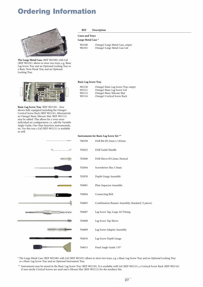
902100 Omega3 Large Metal Case, empty902101 Omega3 Large Metal Case Lid
Basic Lag Screw Tray
902120 Omega3 Basic Lag Screw Tray, empty902121 Omega3 Basic Lag Screw Lid902112 Omega3 Basic Silicone Mat902116 Omega3 Cortical Screw Rack
Instruments for Basic Lag Screw Set **
700358 Drill Bit Ø3.2mm x 145mm
702822 Drill Guide Handle
702840 Drill Sleeve Ø3.2mm, Neutral
702844 Screwdriver Hex 3.5mm
702878 Depth Gauge Assembly
704001 Plate Impactor Assembly
704004 Connecting Bolt
704005 Combination Reamer Assembly, Standard (3 pieces)
704007 Lag Screw Tap, Large AO Fitting
704008 Lag Screw Tap Sleeve
704009 Lag Screw Adapter Assembly
704010 Lag Screw Depth Gauge
704013 Fixed Angle Guide 135º
* The Large Metal Case (REF 902100) with Lid (REF 902101) allows to store two trays, e.g. a Basic Lag Screw Tray and an Optional Locking Tray or a Basic Lag Screw Tray and an Optional Instrument Tray.
** Instruments may be stored in the Basic Lag Screw Tray (REF 902120). It is available with Lid (REF 902121), a Cortical Screw Rack (REF 902116)if non-sterile Cortical Screws are used and a Silcone Mat (REF 902112) for the auxiliary bin.
The Large Metal Case (REF 902100) with Lid(REF 902101) allows to store two trays, e.g. BasicLag Screw Tray and an Optional Locking Tray ora Basic Twin Hook Tray and an OptionalLocking Tray.
Basic Lag Screw Tray (REF 902120) - hereshown fully equipped including the Omega3Cortical Screw Rack (REF 902116). Alternativelyan Omega3 Basic Silicone Mat (REF 902112)may be added. This allows for a even moreindividual set configuration: i.e. add the VariableAngle Guide, One-Step-Insertion instrumentals,etc. For this tray a Lid (REF 902121) is availableas well.

28
Ordering Information
REF Description
Instruments** for Basic Lag Screw Set – Continued
704020 Elastosil® T-Handle, Large AO Fitting
704021 Lag Screw Inserter, Large AO Fitting
704022 Inserter Sleeve
704026 Cleaning Stylet, Ø2.8mm
Guide Wires
704011S Guide Wire Ø2.8mm x 230mm, CoCr, Threaded Tip, Sterile
704012S Guide Wire, Quick Coupling, Ø2.8mm x 230mm, CoCr, Threaded Tip, Sterile
** Instruments may be stored in the Basic Lag Screw Tray (REF 902120). It is available with Lid (REF 902121), a Cortical Screw Rack (REF 902116) if non-sterile Cortical Screws are used and a Silcone Mat (REF 902112) for the auxiliary bin.

29
Ordering Information
REF Description
Optional Locking Tray
902130 Omega3 Optional Locking Tray, empty902131 Omega3 Optional Locking Lid902115 Omega3 Locking Screw Rack
Locking Instruments ***
702430 Elastosil® T-Handle, Medium
702672 Drill Sleeve for Holding Pin, Ø4.9mm, 5.0mm Locking Set
702674 Holding Pin, Ø4.3mm, 5.0mm Locking Set
702708 Drill Sleeve, 5.0mm Locking Set
702743 Calibrated Drill Bit, Ø4.3mm x 262mm, 5.0mm Locking Set, AO Fitting
702748 Screwdriver T20, 5.0mm Locking Set
702751 Universal Torque Limiter, 5.0mm Locking Set, AO•Fitting
702754 Screwdriver T20, 5.0mm Locking Set, AO•Fitting
702763 Locking Insert Inserter, 5.0mm Locking Set
702768 Locking Insert Extractor, 5.0mm Locking Set
702884 Direct Depth Gauge, 5.0mm Locking Set
702969 Locking Insert Forceps, 5.0mm Locking Set
*** Locking instruments may be stored in the Optional Locking Instrument Tray (REF 902130). It is available with Lid (REF 902131), a Screw Rack (REF 902115) if non-sterile Locking Screws are used and a Silicone Mat (REF 902112) for the auxiliary bin.
Omega3 Optional Locking Tray (REF 902130) -here shown fully equipped including theOmega3 Locking Screw Rack (REF 902115) andthe necessary Locking Instruments to performaxial stable fixation of the Omega3 with LockingInserts and Locking Screws. For this tray a Lid(REF 902131) is available as well.

30
Ordering Information
REF Description
Optional Instrument Tray
902135 Omega3 Optional Instrument Tray, empty902136 Omega3 Optional Instrument Lid902113 Omega3 Optional Instrument Silicone Mat
Optional Instruments****
700359 Drill Bit Ø4.5mm x 145mm
702402 Tissue Protection Sleeve, Ø4.5mm / Ø6.5mm
702634 Large AO to Hall Coupling
702773 Tap Ø5.0mm x 140mm, 5.0mm Locking Set, AO Fitting
702808 Tap Ø4.5mm x 145mm, AO Fitting
702809 Tap Ø6.5mm x 145mm, AO Fitting
702823 Drill Sleeve Ø3.2mm, Compression
702853 Screwdriver Hex 3.5mm, AO Fitting
702863 Holding Sleeve for Screwdrivers
702918 Soft Tissue Spreader, 5.0mm Locking Set
704002 One-Step Insertion Wrench
704003 One-Step Insertion Sleeve
704014 Variable Angle Guide, Modular
704019 Guide Pin Replacement Instrument
704025 Drill Sleeve Ø3.2mm, Supracondylar
704205 95º Angle Guide for Supracondylar Plate
704006-20 Barrel Reamer Assembly, Short
704001-1 Plate Impactor Head
900106 Screw Forceps
**** Optional instruments may be stored in the Optional Instrument Tray (REF 902135). It is available with Lid (REF 902136) and Silcone Mat (REF 902113)
The Omega3 Optional Instrument Tray(REF 902135) - shown here equipped withseveral optional instruments like the AngleGuide for Supracondylar Plate, Barrel ReamerShort, One-Step-Insertion-Instruments, etc. For this tray a Lid (REF 902136) and SiliconeMats (REF 902113) are available as well.

31
Stainless Steel Fixed Slots Length Ref Angle mm
597306S 95° 6 111597308S 95° 8 143597310S 95° 10 175597312S 95° 12 207597314S 95° 14 239
Ordering Information – Implants
Omega3 Keyed Supracondylar sideplatesSterile Packaged, 25mm Barrel Length
Stainless Steel Length REF mm
3362-5-050 503362-5-055 553362-5-060 603362-5-065 653362-5-070 703362-5-075 753362-5-080 803362-5-085 853362-5-090 903362-5-095 953362-5-100 1003362-5-105 1053362-5-110 1103362-5-115 1153362-5-120 1203362-5-125 1253362-5-130 130
Stainless Steel Length REF mm
3362-8-050 503362-8-055 553362-8-060 603362-8-065 653362-8-070 703362-8-075 753362-8-080 803362-8-085 853362-8-090 903362-8-095 953362-8-100 1003362-8-105 1053362-8-110 1103362-8-115 1153362-8-120 1203362-8-125 1253362-8-130 130
Stainless Steel Length REF mm
596001S 32.3
Omega Standard Lag Screw, 22mm Thread Length, 13mm Thread Diameter
Omega Super Lag Screw, 22mm Thread Length, 15mm Thread Diameter
Omega Compression Screw
Stainless Steel Fixed Slots Length Ref Angle mm
597326S 95° 6 111597328S 95° 8 143597330S 95° 10 175597332S 95° 12 207597334S 95° 14 239
Omega3 Keyless Supracondylar sideplatesSterile Packaged, 25mm Barrel Length

32
Ordering Information – Implants
Stainless Steel LengthREF mm
340614 14340616 16340618 18340620 20340622 22340624 24340626 26340628 28340630 30340632 32340634 34340636 36340638 38340640 40340642 42340644 44340646 46340648 48340650 50340652 52340654 54340655 55340656 56340658 58340660 60340662 62340664 64340665 65340666 66340668 68340670 70340672 72340674 74340675 75340676 76340678 78340680 80340685 85340690 90340695 95340700 100340705 105340710 110
Cortical Screws ø4.5mm, Self Tapping, Hex 3.5mmStainless Steel LengthREF mm
370314 14370316 16370318 18370320 20370322 22370324 24370326 26370328 28370330 30370332 32370334 34370336 36370338 38370340 40370342 42370344 44370346 46370348 48370350 50370355 55370360 60370365 65370370 70370375 75370380 80370385 85370390 90370395 95
Locking Screws ø5.0mm, Self Tapping, T20 Drive
Stainless Steel DiameterREF mm
370003 14x8.5
5.0mm Locking Insert
Screw lengths 30 –60mm fit into Cortical Screw Rack (REF 902116)
Screw lengths 30 –60mm fit into Locking Screw Rack (REF 902115)
Locking Inserts fit into Locking Screw Rack (REF 902115)
Note: For Sterile, add 'S' to REF
33
Ordering Information – Implants
Stainless Steel LengthREF mm
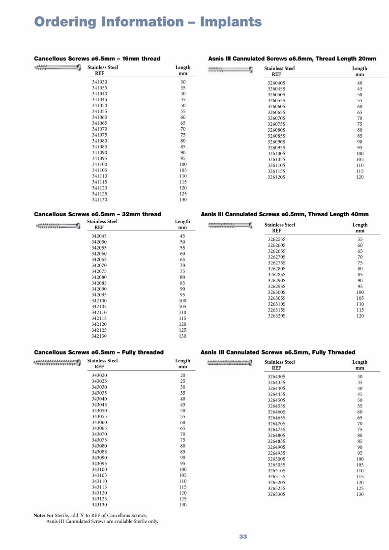
341030 30341035 35341040 40341045 45341050 50341055 55341060 60341065 65341070 70341075 75341080 80341085 85341090 90341095 95341100 100341105 105341110 110341115 115341120 120341125 125341130 130
Cancellous Screws ø6.5mm – 16mm thread
Stainless Steel LengthREF mm
342045 45342050 50342055 55342060 60342065 65342070 70342075 75342080 80342085 85342090 90342095 95342100 100342105 105342110 110342115 115342120 120342125 125342130 130
Cancellous Screws ø6.5mm – 32mm thread
Stainless Steel LengthREF mm
343020 20343025 25343030 30343035 35343040 40343045 45343050 50343055 55343060 60343065 65343070 70343075 75343080 80343085 85343090 90343095 95343100 100343105 105343110 110343115 115343120 120343125 125343130 130
Cancellous Screws ø6.5mm – Fully threaded
Stainless Steel LengthREF mm
326040S 40326045S 45326050S 50326055S 55326060S 60326065S 65326070S 70326075S 75326080S 80326085S 85326090S 90326095S 95326100S 100326105S 105326110S 110326115S 115326120S 120
Asnis III Cannulated Screws ø6.5mm, Thread Length 20mm
Stainless Steel LengthREF mm
326255S 55326260S 60326265S 65326270S 70326275S 75326280S 80326285S 85326290S 90326295S 95326300S 100326305S 105326310S 110326315S 115326320S 120
Asnis III Cannulated Screws ø6.5mm, Thread Length 40mm
Stainless Steel LengthREF mm
326430S 30326435S 35326440S 40326445S 45326450S 50326455S 55326460S 60326465S 65326470S 70326475S 75326480S 80326485S 85326490S 90326495S 95326500S 100326505S 105326510S 110326515S 115326520S 120326525S 125326530S 130
Asnis III Cannulated Screws ø6.5mm, Fully Threaded
Note: For Sterile, add 'S' to REF of Cancellous Screws; Asnis III Cannulated Screws are available Sterile only.

34
Notes

35
Notes

Stryker Trauma AGBohnackerweg 1CH-2545 SelzachSwitzerland
www.osteosynthesis.stryker.com
The information presented in this brochure is intended to demonstrate a Stryker product. Always refer to the packageinsert, product label and/or user instructions before using any Stryker product. Surgeons must always rely on their ownclinical judgment when deciding which products and techniques to use with their patients. Products may not be availablein all markets. Product availability is subject to the regulatory or medical practices that govern individual markets. Please contact your Stryker representative if you have questions about the availability of Stryker products in your area.
Stryker Corporation or its subsidiary owns the registered trademark: StrykerStryker Corporation or its subsidiary owns, uses or has applied for the following trademarks: Omega, Asnis.Swemac Orthopaedics AB owns the following trademark: Hansson.Wacker-Chemie GmbH owns the following trademark: Elastosil
Literature Number: 982311 Rev 2
Copyright © 2007 Stryker