fencing manual - thunderbird.net.authunderbird.net.au/pdf/instructions/universal_energiser... · 1....
TRANSCRIPT

1.
Electric FencingSystems
FENCINGMANUAL
Includes instructions for models
BD20, B20, B60, B120, M25, M60, M120, M250, M350,
M650R, M1150R, M1680R,MB65, MB130, MB250, MB350, MB550R, MB1050R, MB1750R,S15B, S25B, S20B, S40B, S65B,
S70, S1502012 Edition
2.
Contents Topic Page Introduction ............................................................................................................ 4 Warnings ............................................................................................................... 4 Regulations ........................................................................................................... 5 How an Electric Fence Works ............................................................................... 7 Installation ........................................................................................................... 8 Fence Layout ..................................................................................................... 8 Fence Design ..................................................................................................... 9 Post Spacing ............................................................................................... 9 Wire Spacing ............................................................................................... 9 Wire Size ................................................................................................... 10 Upgrading Existing Fences ....................................................................... 10 Fence Corners ........................................................................................... 10 Earthing ............................................................................................................11 Gateways ..........................................................................................................11 Strip or Cell Grazing ........................................................................................ 12 Signs ................................................................................................................ 13 Floodways ........................................................................................................ 13 Energiser Mounting .......................................................................................... 13 Instructions ........................................................................................................ 15 BD20 ................................................................................................................ 15 Specifications ............................................................................................ 17 B20, B60, B120 ............................................................................................... 18 Specifications ............................................................................................ 19 M25, M60, M120, M250, M350 ........................................................................ 20 Specifications ............................................................................................ 21 M650R, M1150R, M1680R .............................................................................. 22 Description ................................................................................................ 22 Mounting .................................................................................................... 22 Fence Connections ................................................................................... 22 Remote Control ......................................................................................... 23 Operation ................................................................................................... 23 Fence Condition ........................................................................................ 24 Specifications ............................................................................................ 25 MB65, MB130, MB250, MB350 ...................................................................... 26 Specifications ............................................................................................ 28 MB550R, MB1050R, MB1750R ...................................................................... 29 16 Character x 2 Line Display ................................................................... 29 Intelligent Adaptive Control ........................................................................ 29
3.
Remote Ready ........................................................................................ 29 Alarm and Siren Outputs ......................................................................... 29 Adjustable Output Voltage....................................................................... 30 Adjustable Pulse Rate ............................................................................. 30 Adjustable Alarm Level............................................................................ 30 Earth Sensing.......................................................................................... 30 Mounting ................................................................................................. 31 Fence Connections ................................................................................. 31 Strobe and Siren Connection .................................................................. 32 Power Supply .......................................................................................... 32 Battery and Solar Panel Selection .......................................................... 32 Operation ................................................................................................ 33 Monitoring Fence Condition .................................................................... 33 Battery Monitoring ................................................................................... 33 Specifications .......................................................................................... 34 S15B, S25B ...................................................................................................... 35 Mounting ................................................................................................. 35 Operation ................................................................................................ 36 Solar Power............................................................................................. 36 Specifications .......................................................................................... 37 S20B, S40B, S65B, S70, S150 ......................................................................... 38 Mounting ................................................................................................. 38 Operation ................................................................................................ 39 Solar Power............................................................................................. 39 Specifications .......................................................................................... 40 Remote Control................................................................................................ 42 Operation ................................................................................................ 42 Security Coding ....................................................................................... 42 Interference ............................................................................................. 43 Battery ..................................................................................................... 43 Trouble Shooting ............................................................................................. 44 Fence Voltage .............................................................................................. 44 TV or Radio Interference ............................................................................. 44 Remote Control ........................................................................................... 45 Phone or Internet Interference ..................................................................... 46 Warranty ........................................................................................................... 47
Contents (Continued) Topic Page

4.
IntroductionThank you for purchasing this product. Thunderbird has had over 20 years experience in manufacturing electric fence equipment. All Thunderbird energisers are manufactured in Mudgee, NSW, and we pride ourselves on being 100% Australian owned.Thunderbird not only manufacture energisers, but a whole range of accessories for electric fencing. Please refer to Thunderbird’s product catalogue to see the range of electric fence accessories available
Please read the warnings, regulations, fence installation, and instructions specific to this model energiser before attempting to install this energiser.
Warnings> Read the relevant sections of this instruction manual fully before
installing or operating the energiser.
> Regular inspections of electric fences must be undertaken to ensure continued operational safety and compliance with Australian Standard AS/NZS 60335.2.76:2003 and AS/NZS 3014:2003.
> Persons coming into contact with high voltage pulses may have their normal physiological functions interrupted.
> Young children and infirm persons should not be left unsupervised in the vicinity of an electric fence energiser or fence.
> Extended periods of sunlight and excessive heat on any liquid crystal display will cause deterioration over time. This is not covered by warranty.
> When using high power energisers, a power reducer device must be in series with the live wire where young children or infirm persons are likely to contact the fence, such as around house yards.
> The mains cord on mains power energisers must be repaired by a qualified electrician if it becomes damaged.
> Only use the power supply provided by Thunderbird for MB energisers. Damage to the energiser may result otherwise.
> Any energiser that operates from mains power must be installed in a dry, well ventilated location such as a shed or building out of the weather.

5.
Regulations Regarding Electric Fence InstallationsThe following information is taken from the Australian Standard AS/NZS 60335.2.76:2003 Amendment 2. Refer to AS/NZS 3014:2003 for the full details on electric fencing.> Electric fences must be installed and operated so that they do not cause an electrical
hazard to persons, animals or their surroundings.> Construction of electric fences that is likely to lead to entanglement of animals or
persons is to be avoided.> An electric fence must not be supplied from two separate energisers or from
independent fence circuits of the same energiser.> For any two separate electric fences that are supplied from separate independently
timed energisers, the distance between the two wires must be at least 2.5 metres. If this gap is to be closer, it must be effected by means of an electrically non-conductive (insulating) material and/or an isolated metal barrier.
> Barbed wire or razor wire must not be electrified by an energiser.> A non-electrified fence incorporating barbed or razor wire may be used to support
one or more offset electrified wires on an electric fence. The supporting devices for the electrified wires must be constructed so as to ensure that these wires are positioned at a minimum distance of 150mm from the vertical plane of the non-electrified wires. The barbed or razor wire must be earthed at regular intervals in accordance with Country Electronics earthing recommendations. (See chapter on earthing)
> A distance of at least 10 metres must be maintained between the energiser’s earth electrode and any other earthing system connected parts - eg, mains power protective earth or telecommunications system earth.
> Electric fence connecting leads located inside buildings must be effectively insulated from the earthed structural parts of the building - use suitable high voltage insulated cable. Important: always ensure metal parts of the building are effectively earthed.
> Electric fence connecting leads located underground must be run in a suitable conduit of insulating material, or high voltage insulated cable be used. Care must be taken that the effects of animal hooves or vehicle wheels sinking into the ground cannot damage the connecting leads.
> Electric fence connecting leads must not be installed in the same conduit as mains supply wiring, communications cables or data cables.
> Crossing with overhead power lines must be avoided wherever possible. If such a
6.
crossing cannot be avoided, it must be made underneath the power line and near as possible right angles to it.
> If electric fence connecting leads and wires are installed near an overhead power line, the clearances must not be less than indicated in the table below.
Power Line Voltage - V Clearances - Metres Up to 1000V 3 1000V - 33000V 4 Above 33000V 8> If electric fence connecting leads and wires are installed near an overhead power line,
their height above the ground must not exceed 3 metres. This height applies either side of the orthogonal projection of the outermost conductors of the power line on the ground surface, for a distance of:
- 2 metres for power lines operating at a voltage not exceeding 1000V
- 15 metres for power lines operating at a voltage exceeding 1000V
> Electric fences intended for deterring birds from roosting on buildings, no electric fence wire shall be connected to an earth electrode. A warning sign must be fitted to every point where a person or persons may gain access to the conductors.
> Where an electric fence crosses a public pathway, a non-electrified gate must be incorporated into the electric fence at that point, or a crossing by means of stiles must be provided. At any such crossing, the adjacent electrified wires must carry warning signs.
> Any part of an electric fence that is installed along a public road or pathway must be identified at frequent intervals by warning signs securely fastened to the fence posts or firmly clamped to the fence wires.
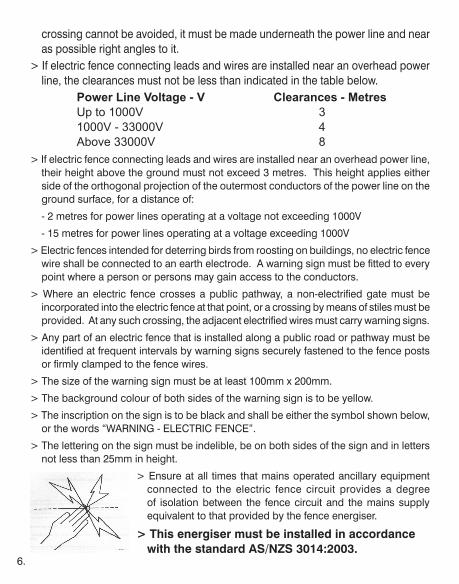
> The size of the warning sign must be at least 100mm x 200mm.
> The background colour of both sides of the warning sign is to be yellow.
> The inscription on the sign is to be black and shall be either the symbol shown below, or the words “WARNING - ELECTRIC FENCE”.
> The lettering on the sign must be indelible, be on both sides of the sign and in letters not less than 25mm in height.
> Ensure at all times that mains operated ancillary equipment connected to the electric fence circuit provides a degree of isolation between the fence circuit and the mains supply equivalent to that provided by the fence energiser.
> This energiser must be installed in accordance with the standard AS/NZS 3014:2003.
7.
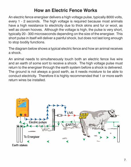
How an Electric Fence WorksAn electric fence energiser delivers a high voltage pulse, typically 8000 volts, every 1 - 2 seconds. The high voltage is required because most animals have a high resistance to electricity due to thick skins and fur or wool, as well as cloven hooves. Although the voltage is high, the pulse is very short, typically 20 - 300 microseconds depending on the size of the energiser. This short pulse in itself will deliver a painful shock, but does not last long enough to stop bodily functions.
The diagram below shows a typical electric fence and how an animal receives a shock.
An animal needs to simultaneously touch both an electric fence live wire and an earth of some sort to receive a shock. The high voltage pulse must return to the energiser through the earth system before a shock is delivered. The ground is not always a good earth, as it needs moisture to be able to conduct electricity. Therefore it is highly recommended that 1 or more earth return wires be installed.
8.
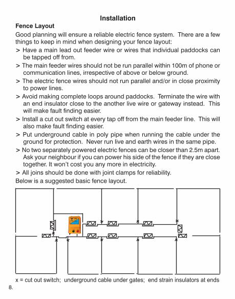
InstallationFence LayoutGood planning will ensure a reliable electric fence system. There are a few things to keep in mind when designing your fence layout:> Have a main lead out feeder wire or wires that individual paddocks can
be tapped off from.> The main feeder wires should not be run parallel within 100m of phone or
communication lines, irrespective of above or below ground.> The electric fence wires should not run parallel and/or in close proximity
to power lines.> Avoid making complete loops around paddocks. Terminate the wire with
an end insulator close to the another live wire or gateway instead. This will make fault finding easier.
> Install a cut out switch at every tap off from the main feeder line. This will also make fault finding easier.
> Put underground cable in poly pipe when running the cable under the ground for protection. Never run live and earth wires in the same pipe.
> No two separately powered electric fences can be closer than 2.5m apart. Ask your neighbour if you can power his side of the fence if they are close together. It won’t cost you any more in electricity.
> All joins should be done with joint clamps for reliability.Below is a suggested basic fence layout.
x = cut out switch; underground cable under gates; end strain insulators at ends
9.
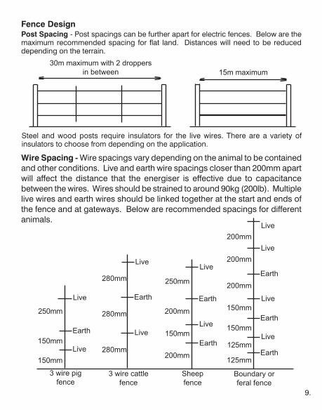
Steel and wood posts require insulators for the live wires. There are a variety of insulators to choose from depending on the application.
30m maximum with 2 droppers in between 15m maximum
Wire Spacing - Wire spacings vary depending on the animal to be contained and other conditions. Live and earth wire spacings closer than 200mm apart will affect the distance that the energiser is effective due to capacitance between the wires. Wires should be strained to around 90kg (200lb). Multiple live wires and earth wires should be linked together at the start and ends of the fence and at gateways. Below are recommended spacings for different animals.
150mm
125mm200mm
280mm150mm
150mm
150mm
150mm
250mm 200mm
200mm
200mm
200mm
280mm
280mm 250mm
125mm
Live
Earth
Live
Live
Live
Live
Live
Live
Live
Live
Live
Earth
Earth
Earth
Earth
Earth
Earth
3 wire pig fence
3 wire cattle fence
Sheep fence
Boundary or feral fence
Fence DesignPost Spacing - Post spacings can be further apart for electric fences. Below are the maximum recommended spacing for flat land. Distances will need to be reduced depending on the terrain.
10.
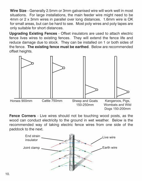
Upgrading Existing Fences - Offset insulators are used to attach electric fence lives wires to existing fences. They will extend the fence life and reduce damage due to stock. They can be installed on 1 or both sides of the fence. The existing fence must be earthed. Below are recommended offset heights.
Horses 900mm Cattle 750mm Sheep and Goats 150-250mm
Kangaroos, Pigs, Wombats and Wild Dogs 150-200mm
End strain insulator
Live wire
Joint clamp Earth wire
Wire Size - Generally 2.5mm or 3mm galvanised wire will work well in most situations. For large installations, the main feeder wire might need to be 4mm or 2 x 3mm wires in parallel over long distances. 1.6mm wire is OK for small areas, but can be hard to see. Most poly wires and poly tapes are only suitable for short distances.
Fence Corners - Live wires should not be touching wood posts, as the wood can conduct electricity to the ground in wet weather. Below is the recommended way of taking electric fence wires from one side of the paddock to the next.
11.
Earthing
Good earthing is just as important, if not more important, as the live wire. The earth system must conduct the electricity back to the energiser in order for the animal to receive a shock. Things to keep in mind are:
> Earth stakes must be driven at least 1.5m into the ground.
> Only use galvanised or stainless steel earth stakes. Do not use copper or tar covered fence posts.
> Electric fence earth stakes must be a minimum of 10m from any existing electrical or communication earthing.
> Position earth stakes in a permanently moist area if possible.
> Earth return wires in the fence are required for good earthing. Ground return earthing is only suitable for strip grazing with moist soil.
> A minimum of 1 earth stake is required at the energiser for power levels below 1.5 joules, 2 earth stakes for power levels below 4 joules, and 3 earth stakes for power levels above 4 joules.
> Additional earth stakes are required every 1.5km along a fence. Use wire joint clamps to connect the earth stakes to non-electrified wires and to any existing fences.
> Use Thunderbird Super Earth Kits in dry soils such as sandy or rocky areas (bentonite type).
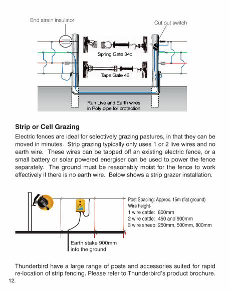
Gateways
Electric fence cables that need to cross a gateway can be buried under ground. Use double insulated underground electric fence cable for both live and earth wires and run inside poly pipe for protection. The cables should be buried 300mm underneath the ground. Do not put both live and earth wires in the same pipe.
The ends of the poly pipe should be bent over to face the ground so that rain doesn’t fill the pipe. It is highly recommended that a cut out switch be used in the live wire supply side entering the pipe so that it is easier to locate a fault should a short occur under ground.Illustration on next page shows a typical gateway installation.
12.
Strip or Cell GrazingElectric fences are ideal for selectively grazing pastures, in that they can be moved in minutes. Strip grazing typically only uses 1 or 2 live wires and no earth wire. These wires can be tapped off an existing electric fence, or a small battery or solar powered energiser can be used to power the fence separately. The ground must be reasonably moist for the fence to work effectively if there is no earth wire. Below shows a strip grazer installation.
Earth stake 900mm into the ground
Post Spacing: Approx. 15m (flat ground)Wire height-1 wire cattle: 800mm2 wire cattle: 450 and 900mm3 wire sheep: 250mm, 500mm, 800mm
End strain insulator
Thunderbird have a large range of posts and accessories suited for rapid re-location of strip fencing. Please refer to Thunderbird’s product brochure.
Cut out switch
13.
Signs
Electric fence warning signs must be placed at regular intervals along electric fences where there is a possibility of the general public coming into contact with the fence. This is an Australian Standard requirement. Such situations are where the fence runs parallel with or crosses over a public road, or where the fence comes in proximity to a public pathway. A warning sign must be placed both sides of the road where an electric fence crosses the road.
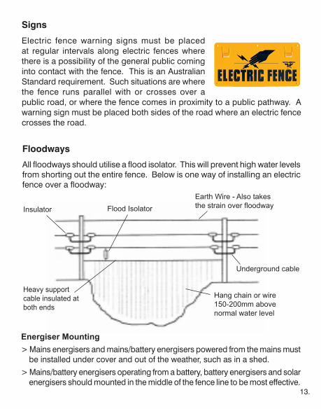
Floodways
All floodways should utilise a flood isolator. This will prevent high water levels from shorting out the entire fence. Below is one way of installing an electric fence over a floodway:
Hang chain or wire 150-200mm above normal water level
Heavy support cable insulated at both ends
Flood IsolatorInsulator
Earth Wire - Also takes thestrainoverfloodway
Underground cable
Energiser Mounting> Mains energisers and mains/battery energisers powered from the mains must
be installed under cover and out of the weather, such as in a shed.
> Mains/battery energisers operating from a battery, battery energisers and solar energisers should mounted in the middle of the fence line to be most effective.
14.
> BD20, B20, B60 and B120 energisers have hanger clips on top, and can simply be suspended from a fence wire.
> Solar energisers are designed to sit over the top of a metal star post.
> Solar energisers and solar panels must face the equator and be in a position where shade cannot block the sun from the solar panel.
> All energisers should be mounted up out of the reach of children.
> Do not allow any energiser to operate by sitting it on the ground.
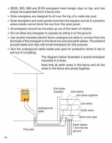
> Use double insulated electric fence underground cable to connect from the terminals of the energiser to the fence live wire and earth stakes. Thunderbird provide leads and clips with small energisers for this purpose.
> Run the undergound cable inside poly pipe for protection where it has to exit out of a building.
The diagram below illustrates a typical energiser mounted in a shed.
Note that all earth wires in the fence and all live wires in the fence are joined together.
Poly pipe
Earth stakes 1.5m into the ground
Bend over pipe
Live wires
End strain insulator Joint clamp
Earth wires
Join wires together
Underground cable
15.
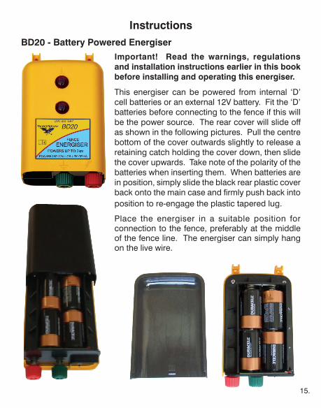
InstructionsBD20 - Battery Powered Energiser
Important! Read the warnings, regulations and installation instructions earlier in this book before installing and operating this energiser.
This energiser can be powered from internal ‘D’ cell batteries or an external 12V battery. Fit the ‘D’ batteries before connecting to the fence if this will be the power source. The rear cover will slide off as shown in the following pictures. Pull the centre bottom of the cover outwards slightly to release a retaining catch holding the cover down, then slide the cover upwards. Take note of the polarity of the batteries when inserting them. When batteries are in position, simply slide the black rear plastic cover back onto the main case and firmly push back into position to re-engage the plastic tapered lug.
Place the energiser in a suitable position for connection to the fence, preferably at the middle of the fence line. The energiser can simply hang on the live wire.
16.
It’s recommended that bolts or pieces of tie wire be put through the holes in the mounting lugs to make sure that the energiser doesn’t bounce off the live wire. Drive one or more galvanised earth stakes approximately 1m into the ground. Refer to the strip grazer section and the earthing section of the installation chapter.
NOTE: Hot tape and polywire can be used effectively for lengths up to 400m from the energiser. Thundertape and Thundercord can be used on runs up to 1km in any direction. Use galvanised fencing wire for longer distances. Refer to the poly tape section in Thunderbird’s product brochure.
Make sure the energiser is turned off before connecting the fence wires to prevent receiving a shock. A green earth lead with an insulated clip and a ring, and a red fence lead with insulated clip are supplied. Simply undo the green earth knob from the terminal at the base of the energiser and place the ring over the bolt. Screw the green knob back onto the terminal bolt firmly. Similarly for the red fence terminal and red lead. Clip the green insulated clip to the galvanised earth stake that has been driven into the ground. Connect the red clip to the live fence wire.
If using a 12V battery, connect the red battery clip of the battery lead to the positive terminal of the battery and the black clip to the negative terminal, then plug the lead into the energiser.
The switch on the bottom of the energiser can be switched to high or low power for operation. Good quality alkaline ‘D’ cells will last for approximately 5 weeks with the energiser running continuously on low power. Low power is good enough for containing horses and other domestic animals in small areas, but high power is recommended for longer fence lengths.
The top light flashes with every energiser pulse. The bottom light is a low battery indication that flashes with every pulse if battery voltage falls below 12.0V (nominal). This energiser has intelligent battery monitoring. If the battery starts getting flat the output voltage will reduce to conserve the bat-tery. If the battery voltage falls to approximately 11.5V the low battery light will give a double flash every pulse. Once the battery voltage falls to 11V the energiser will stop and the low battery light will be continuously on. The
17.
energiser will start operating normally again when the battery voltage exceeds 12V. These cut outs are intended to protect your battery.
This energiser also has built in self testing. If there is a problem with the unit you will see multiple flashes with each pulse. If the energiser pulse light flashes normally and there is low or no output, assume that there is a problem with the fence. Refer to the troubleshooting section.
SPECIFICATIONS
Input Voltage ............ 12.7V nominal on dc input - Maximum 20V Input Current ............ 15mA at 13V on high power 10mA at 13V on low power 26mA at 6V on high power 16mA at 6V on low power Output Voltage ......... 7.5kV (nominal) on high power 6.0kV (nominal) on low power Stored Energy .......... 0.16 joules on high power 0.1 joules on low power Maximum Output ..... 0.12 joules into 1000 ohms Temperature ............. -10 - 50 degrees Celsius Humidity ................... Maximum 90% non-condensing
18.
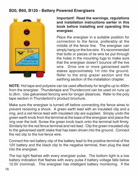
B20, B60, B120 - Battery Powered Energisers
Important! Read the warnings, regulations and installation instructions earlier in this book before installing and operating this energiser.
Place the energiser in a suitable position for connection to the fence, preferably at the middle of the fence line. The energiser can simply hang on the live wire. It’s recommended that bolts or pieces of tie wire be put through the holes in the mounting lugs to make sure that the energiser doesn’t bounce off the live wire. Drive one or more galvanised earth stakes approximately 1m into the ground. Refer to the strip grazer section and the earthing section of the installation chapter.
NOTE: Hot tape and polywire can be used effectively for lengths up to 400m from the energiser. Thundertape and Thundercord can be used on runs up to 2km. Use galvanised fencing wire for longer distances. Refer to the poly tape section in Thunderbird’s product brochure.
Make sure the energiser is turned off before connecting the fence wires to prevent receiving a shock. A green earth lead with an insulated clip and a ring, and a red fence lead with insulated clip are supplied. Simply undo the green earth knob from the terminal at the base of the energiser and place the ring over the bolt. Screw the green knob back onto the terminal bolt firmly. Similarly for the red fence terminal and red lead. Clip the green insulated clip to the galvanised earth stake that has been driven into the ground. Connect the red clip to the live fence wire.
Connect the red battery clip of the battery lead to the positive terminal of the 12V battery and the black clip to the negative terminal, then plug the lead into the energiser.
The top light flashes with every energiser pulse. The bottom light is a low battery indication that flashes with every pulse if battery voltage falls below 12.0V (nominal). This energiser has intelligent battery monitoring. If the

19.
battery starts getting flat the output voltage will reduce to conserve the battery. If the battery voltage falls to approximately 11.5V the low battery light will give a double flash every pulse. Once the battery voltage falls to 11V the energiser will stop and the low battery light will be continuously on. The energiser will start operating normally again when the battery voltage exceeds 12V. These cut outs are intended to protect your battery.
This energiser also has built in self testing. If there is a problem with the unit you will see multiple flashes with each pulse. If the energiser pulse light flashes normally and there is low or no output, assume that there is a problem with the fence. Refer to the troubleshooting section.
Solar Panel Sizes - In situations where a battery and solar panel are required, the minimum recommended solar panel sizes are:
B20 - 2W solar panelB60 - 4W solar panelB120 - 8W solar panel
SPECIFICATIONS
Input Voltage .....................12.7V nominal - Maximum 20VInput Current at 13V .........B20 - 15mA B60 - 44mA B120 - 105mAOutput Voltage ..................B20 - 7.5kV (nominal) no load B60 - 8.1kV (nominal) no load B120 - 8.1kV (nominal) no loadStored Energy ...................B20 - 0.16 joules B60 - 0.7 joules B120 - 1.5 joulesMaximum Output Energy B20 - 0.11 joules into 1000 ohms B60 - 0.48 joules into 500 ohms B120 - 1.0 joule into 330 ohmsTemperature ......................-10 - 50 degrees CelsiusHumidity ............................Maximum 90% non-condensing
20.
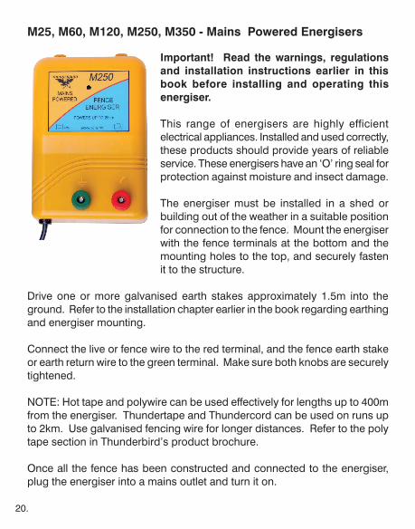
M25, M60, M120, M250, M350 - Mains Powered Energisers
Important! Read the warnings, regulations and installation instructions earlier in this book before installing and operating this energiser.
This range of energisers are highly efficient electrical appliances. Installed and used correctly, these products should provide years of reliable service. These energisers have an ‘O’ ring seal for protection against moisture and insect damage.
The energiser must be installed in a shed or building out of the weather in a suitable position for connection to the fence. Mount the energiser with the fence terminals at the bottom and the mounting holes to the top, and securely fasten it to the structure.
Drive one or more galvanised earth stakes approximately 1.5m into the ground. Refer to the installation chapter earlier in the book regarding earthing and energiser mounting.
Connect the live or fence wire to the red terminal, and the fence earth stake or earth return wire to the green terminal. Make sure both knobs are securely tightened.
NOTE: Hot tape and polywire can be used effectively for lengths up to 400m from the energiser. Thundertape and Thundercord can be used on runs up to 2km. Use galvanised fencing wire for longer distances. Refer to the poly tape section in Thunderbird’s product brochure.
Once all the fence has been constructed and connected to the energiser, plug the energiser into a mains outlet and turn it on.
21.
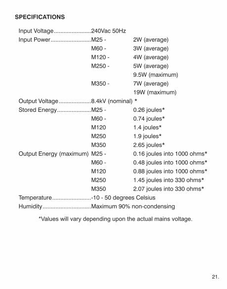
SPECIFICATIONS
Input Voltage .......................240Vac 50HzInput Power .........................M25 - 2W (average) M60 - 3W (average) M120 - 4W (average) M250 - 5W (average) 9.5W (maximum) M350 - 7W (average) 19W (maximum)Output Voltage ....................8.4kV (nominal) *Stored Energy .....................M25 - 0.26 joules* M60 - 0.74 joules* M120 1.4 joules* M250 1.9 joules* M350 2.65 joules*Output Energy (maximum) M25 - 0.16 joules into 1000 ohms* M60 - 0.48 joules into 1000 ohms* M120 0.88 joules into 1000 ohms* M250 1.45 joules into 330 ohms* M350 2.07 joules into 330 ohms*Temperature ........................-10 - 50 degrees CelsiusHumidity ..............................Maximum 90% non-condensing
*Values will vary depending upon the actual mains voltage.

22.
M650R, M1150R, M1680R - Mains Powered Energisers
Important! Read the warnings, regulations and installation instructions earlier in this book before installing and operating this energiser.
This range of energisers are highly efficient electrical appliances. Installed and used correctly, these products should provide years of reliable service. These energisers have an ‘O’ ring seal for protection against moisture and insect damage.
Description - The M650R, M1150R and M1680R are a low cost, high reliability electric fence energiser designed for the harsh Australian climate. They feature a digital display for fence voltage indication, improved efficiency, remote control
capability, and a tough impact resistant case.
These remote ready electric fence energisers can be turned from standby to on or vice versa from any point along its electric fence by means of an optional remote control. This is a valuable time and fuel saving feature when additions, repairs or access is required on the fence system. The remote control is capable of operating even when there is a heavy load on the fence.
Mounting - The energiser must be mounted in a vertical position under cover, such as in a shed. Use underground cable to connect the energiser to the fence and to the earth stakes. DO NOT leave the energiser laying on the ground.
The remote control, if used, should be stowed in a safe place away from moisture and rough treatment.
Drive three or more galvanised earth stakes approximately 1.5m into the ground. Refer to the installation chapter earlier in the book regarding earthing and installation.
Fence Connections - Connect the main fence live wire to the “HIGH POWER”
23.
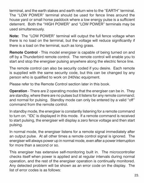
terminal, and the earth stakes and earth return wire to the “EARTH” terminal. The “LOW POWER” terminal should be used for fence lines around the house yard or small horse paddock where a low energy pulse is a sufficient deterrent. Both the “HIGH POWER” and “LOW POWER” terminals may be used simultaneously.
Note: The “LOW POWER” terminal will output the full fence voltage when there is no load on the terminal, but the voltage will reduce significantly if there is a load on the terminal, such as long grass.
Remote Control - This model energiser is capable of being turned on and off by a Thunderbird remote control. The remote control will enable you to start and stop the energiser pulsing anywhere along the electric fence line.
The remote control can also be security coded if you desire. Each remote is supplied with the same security code, but this can be changed by any person who is qualified to work on 240Vac equipment.
Please refer to the Remote Control section later in this book.
Operation - There are 2 operating modes that the energiser can be in. They are standby, where there are no pulses but it listens for any remote command; and normal for pulsing. Standby mode can only be entered by a valid “off” command from the remote control.
In standby mode, the energiser is constantly listening for a remote command to turn on. “IDL” is displayed in this mode. If a remote command is received to start pulsing, the energiser will display a zero fence voltage and then start pulsing.
In normal mode, the energiser listens for a remote signal immediately after an output pulse. At all other times a remote control signal is ignored. The energiser will always power up in normal mode, even after a power interruption for more than a second or so.
This energiser has extensive self-monitoring built in. The microcontroller checks itself when power is applied and at regular intervals during normal operation, and the rest of the energiser operation is continually monitored. Any detected problem will be shown as an error code on the display. The list of error codes is as follows:
24.
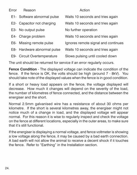
Error Reason Action
E1- Software abnormal pulse Waits 10 seconds and tries again
E2- Capacitor not charging Waits 10 seconds and tries again
E3- No output pulse No further operation
E4- Charge problem Waits 10 seconds and tries again
E6- Missing remote pulse Ignores remote signal and continues
E8- Hardware abnormal pulse Waits 10 seconds and tries again
E9- Circuit Overtemperature Slows pulsing until cooled down
The unit should be returned for service if an error regularly occurs.
Fence Condition - The displayed voltage can indicate the condition of the fence. If the fence is OK, the volts should be high (around 7 - 8kV). You should take note of the displayed values when the fence is in good condition.
If a short or heavy load appears on the fence, the voltage displayed will decrease. How much it changes will depend on the severity of the load, the number of kilometres of fence connected, and the distance between the energiser and the short.
Normal 2.5mm galvanised wire has a resistance of about 30 ohms per kilometre. If the short is several kilometres away, the energiser might not notice much of a change in load, and the displayed voltage will appear normal. For this reason it is wise to regularly inspect and check the voltage on the fence at different locations, especially in the outer areas, to make sure that it’s still functional.
If the energiser is displaying a normal voltage, and fence voltmeter is showing a low voltage along the fence, it may be caused by a bad earth connection. A bad earth will not allow the animal to receive a decent shock if it touches the fence. Refer to “Earthing” in the Installation section.
25.
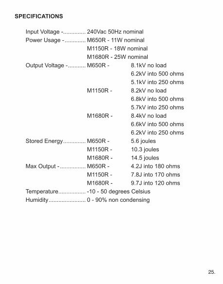
SPECIFICATIONS
Input Voltage -.............. 240Vac 50Hz nominal Power Usage - ............. M650R - 11W nominal M1150R - 18W nominal M1680R - 25W nominal Output Voltage - ........... M650R - 8.1kV no load 6.2kV into 500 ohms 5.1kV into 250 ohms M1150R - 8.2kV no load 6.8kV into 500 ohms 5.7kV into 250 ohms M1680R - 8.4kV no load 6.6kV into 500 ohms 6.2kV into 250 ohms Stored Energy .............. M650R - 5.6 joules M1150R - 10.3 joules M1680R - 14.5 joules Max Output - ................ M650R - 4.2J into 180 ohms M1150R - 7.8J into 170 ohms M1680R - 9.7J into 120 ohms Temperature................. -10 - 50 degrees Celsius Humidity ....................... 0 - 90% non condensing

26.
MB65, MB130, MB250, MB350 - Mains or Battery Powered Energisers
Important! Read the warnings, regulations and installation instructions earlier in this book before installing and operating this energiser.
This range of energisers are highly efficient electrical appliances. Installed and used correctly, these products should provide years of reliable service. These energisers have an ‘O’ ring seal for protection against moisture and insect damage.
This energiser is supplied with both a 13V plug pack ac adaptor for connection to the mains, as well as a battery lead for connection to a 12V battery. Always operate the energiser under cover.
Place the energiser in a suitable position under cover for connection to the fence, preferably at the middle of the fence line if powered by a battery. Install the energiser in a shed or building if powered by a mains plug pack adaptor. Mount energiser upright with fence terminals to bottom and mounting holes to the top, tighten fasteners to secure energiser to the structure. Refer to the Installation section earlier in this book for fence construction and earthing.
Connect the live wire to the fence or red terminal, and the earth stake to the earth or green terminal. Once all the fence has been installed, and is being powered by a battery, connect the red battery clip to the positive terminal of a 12V battery and the black clip to the negative terminal, and plug the power lead into the bottom of the energiser.
The display shows the voltage in kV at the terminals of the energiser. This
27.
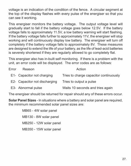
voltage is an indication of the condition of the fence. A circular segment at the top of the display flashes with every pulse of the energiser so that you can see it working.
This energiser monitors the battery voltage. The output voltage level will gradually start to fall if the battery voltage goes below 12.5V. If the battery voltagefallstoapproximately11.5V,alowbatterywarningwillstartflashing.If the battery voltage falls further to approximately 11V, the energiser will stop working and will continuously display low battery. The energiser will turn off completely if the battery voltage falls to approximately 8V. These measures are designed to extend the life of your battery, as the life of lead-acid batteries isseverelyshortenediftheyareregularlyallowedtogocompletelyflat.
This energiser also has in-built self monitoring. If there is a problem with the unit, an error code will be displayed. The error codes are as follows:
Error Reason Action
E1- Capacitor not charging Tries to charge capacitor continuously
E2- Capacitor not discharging Tries to output a pulse
E3- Abnormal pulse Waits 10 seconds and tries again
The energiser should be returned for repair should any of these errors occur.
Solar Panel Sizes - In situations where a battery and solar panel are required, the minimum recommended solar panel sizes are:
MB65 - 4W solar panel
MB130 - 8W solar panel
MB250 - 12W solar panel
MB350 - 15W solar panel
28.
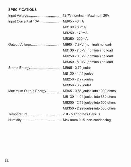
SPECIFICATIONSInput Voltage....................................12.7V nominal - Maximum 20V
Input Current at 13V ........................ MB65 - 43mA
MB130 - 88mA
MB250 - 170mA
MB350 - 220mA
Output Voltage ................................. MB65 - 7.8kV (nominal) no load
MB130 - 7.8kV (nominal) no load
MB250 - 8.0kV (nominal) no load
MB350 - 8.0kV (nominal) no load
Stored Energy.................................. MB65 - 0.72 joules
MB130 - 1.44 joules
MB250 - 2.77 joules
MB350 - 3.7 joules
Maximum Output Energy ................. MB65 - 0.55 joules into 1000 ohms
MB130 - 1.04 joules into 330 ohms
MB250 - 2.19 joules into 500 ohms
MB350 - 2.92 joules into 500 ohms
Temperature .................................... -10 - 50 degrees Celsius
Humidity........................................... Maximum 90% non-condensing

29.
MB550R, MB1050R, MB1750R - Mains or Battery Powered Energisers
Important! Read the warnings, regulations and installation instructions earlier in this book before installing and operating this energiser.
This energiser is supplied with both a 13V plug pack ac adaptor for connection to the mains, as well as a battery lead for connection to a 12V battery. Always operate the energiser under cover.
This energiser is packed with numerous features to enable you to tailor the unit to suit your needs. The features are explained as follows:
16 Character x 2 Line Display - The display indicates the condition of the fence as viewed
by the energiser. Fence voltage, current, stored joules and earth voltage are displayed while the unit is running. Set up menus, error messages and other information are easily read in plain English. A backlight aids viewing the information, but turns off after a few seconds to conserve the battery.
Intelligent Adaptive Control - This feature allows the energiser to be more efficient in its use of energy from the power source, and yet deliver maximum voltage when the fence becomes heavily loaded. As much as 55% power saving can be achieved by maintaining a well insulated fence that is free from excessive loads.
Remote Ready - This energiser can be turned from standby to on or vice versa from any point along the fence by means of an optional remote control. Refer to the remote control section later in the book.
Alarm and Siren Outputs - Early warning of a problem with the fence can be achieved by plugging in an optional strobe or siren/strobe. The siren and strobe will be activated if the fence voltage falls below the set alarm level. An alarm will also be indicated if the earth voltage is too high. The siren will automatically turn off after 5 minutes to comply with noise laws, but the strobe
30.
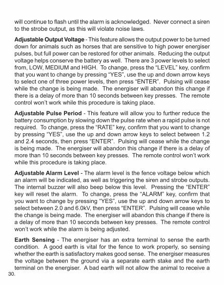
will continue to flash until the alarm is acknowledged. Never connect a siren to the strobe output, as this will violate noise laws.
Adjustable Output Voltage - This feature allows the output power to be turned down for animals such as horses that are sensitive to high power energiser pulses, but full power can be restored for other animals. Reducing the output voltage helps conserve the battery as well. There are 3 power levels to select from,LOW,MEDIUMandHIGH.Tochange,pressthe“LEVEL”key,confirmthat you want to change by pressing “YES”, use the up and down arrow keys to select one of three power levels, then press “ENTER”. Pulsing will cease while the change is being made. The energiser will abandon this change if there is a delay of more than 10 seconds between key presses. The remote control won’t work while this procedure is taking place.
Adjustable Pulse Period - This feature will allow you to further reduce the battery consumption by slowing down the pulse rate when a rapid pulse is not required.Tochange,pressthe“RATE”key,confirmthatyouwanttochangeby pressing “YES”, use the up and down arrow keys to select between 1.2 and 2.4 seconds, then press “ENTER”. Pulsing will cease while the change is being made. The energiser will abandon this change if there is a delay of more than 10 seconds between key presses. The remote control won’t work while this procedure is taking place.
Adjustable Alarm Level - The alarm level is the fence voltage below which an alarm will be indicated, as well as triggering the siren and strobe outputs. The internal buzzer will also beep below this level. Pressing the “ENTER” keywill reset thealarm.Tochange,pressthe“ALARM”key,confirmthatyou want to change by pressing “YES”, use the up and down arrow keys to select between 2.0 and 6.0kV, then press “ENTER”. Pulsing will cease while the change is being made. The energiser will abandon this change if there is a delay of more than 10 seconds between key presses. The remote control won’t work while the alarm is being adjusted.
Earth Sensing - The energiser has an extra terminal to sense the earth condition. A good earth is vital for the fence to work properly, so sensing whether the earth is satisfactory makes good sense. The energiser measures the voltage between the ground via a separate earth stake and the earth terminal on the energiser. A bad earth will not allow the animal to receive a
31.
decent shock if it touches the fence. Refer to “Earthing” in the Installation section.
If the earth voltage rises above 1kV for more than 10 consecutive pulses, a warning will be displayed. If the earth voltage rises above 3kV for more than 10 consecutive pulses, an alarm will be displayed, the internal buzzer will beep continuously, and the strobe and siren outputs will be activated. The earth voltage will only rise above 3kV if the earth lead has become detached from the earth stake or the energiser. This alarm can be reset, but will occur againafter10pulsesiftheproblemisnotfixed.
It is not mandatory that the earth sense terminal be used. Simply leave it unconnected and ignore any displayed earth voltage if you don’t want to use this feature. The diagram below shows how to implement earth sensing.
The earth sense stake must be a minimum of 10m from other fence earths.
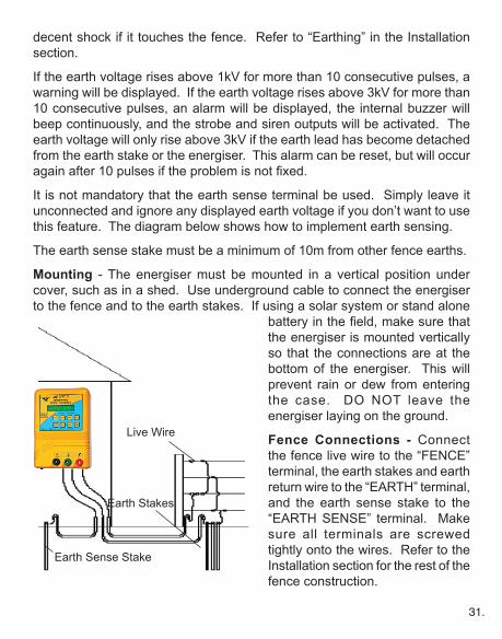
Mounting - The energiser must be mounted in a vertical position under cover, such as in a shed. Use underground cable to connect the energiser to the fence and to the earth stakes. If using a solar system or stand alone
batteryinthefield,makesurethatthe energiser is mounted vertically so that the connections are at the bottom of the energiser. This will prevent rain or dew from entering the case. DO NOT leave the energiser laying on the ground.
Fence Connections - Connect the fence live wire to the “FENCE” terminal, the earth stakes and earth return wire to the “EARTH” terminal, and the earth sense stake to the “EARTH SENSE” terminal. Make sure all terminals are screwed tightly onto the wires. Refer to the Installation section for the rest of the fence construction.
Live Wire
Earth Sense Stake
Earth Stakes

32.
Strobe and Siren Connection - There is a 6.5mm stereo socket available on the bottom of the enclosure. This is for connecting a strobe and/or siren as an external alarm indication. The strobe supplied by Thunderbird has a plug suited to this socket. DO NOT apply an external 12V to the strobe or siren! The energiser powers the strobe and siren outputs itself from the 12V source. Below is the connection diagram. A maximum of 500mA may be drawn from each connection to power the strobe and siren.
Power Supply - A socket is provided on the bottom of the energiser for connecting the provided mains power supply or a 12V battery. A battery lead with clips is provided to connect to a 12V battery. Keep the battery lead as short as possible if you are using a 12V battery. Long battery leads can have a significant voltage drop, which reduces the voltage reaching the energiser and affect its performance.
Battery and Solar Panel Selection - For solar use or stand alone battery use, the minimum recommended sizes are:
MB550R - 100 amp hour deep cycle or solar rated
MB1050R - 200 amp hour deep cycle or solar rated
MB1750R - 280 amp hour deep cycle or solar rated
These battery sizes will give a maximum of approximately 10 days running time without any charge. Repeatedly discharging a lead-acid battery by more than 40-50% will severely shorten its life.
The minimum recommended sizes of solar panels are as follows:
MB550R - 40W solar panel
MB1050R - 80W solar panel
MB1750R - 120W solar panel
These panels require a solar regulator. The output of the regulator should be connected directly to the battery.
Ensure that the solar panel is facing the equator, and that it can receive full
Common Supply
Siren
Strobe
33.
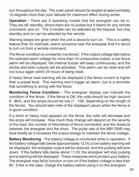
sun throughout the day. The solar panel should be angled at approximately 10 degrees more than your latitude for maximum effect during winter.
Operation - There are 3 operating modes that the energiser can be in. They are off; standby, where there are no pulses but it listens for any remote command; and on. The 3 modes can be selected by the keypad, but only standby and on can be selected by the remote.
Warning beeps are given when the unit is about to turn on. This is a safety feature that, for example, warns someone near the energiser that it’s about to turn on from a remote command.
The fence condition is constantly monitored. If the output voltage falls below the selected alarm voltage for more than 10 consecutive pulses, a low fence alarm will be displayed, the internal buzzer will beep continuously, and the strobe and siren outputs will be activated. This alarm can be reset and will not occur again within 24 hours of being reset.
A heavy fence load warning will be displayed if the fence current is higher than a preset level. This warning won’t trigger an alarm, but is a reminder that something is wrong with the fence.
Monitoring Fence Condition - The energiser display can indicate the condition of the fence. If the fence is OK, the volts should be high (around 6 - 8kV), and the amps should be low (1 - 10A, depending on the length of the fence). You should take note of the displayed values when the fence is in good condition.
If a short or heavy load appears on the fence, the volts will decrease and the amps will increase. How much they change will depend on the severity of the load, the number of kilometres of fence connected, and the distance between the energiser and the short. The pulse rate of the MB1750R may slow briefly as it increases the output energy to maintain the fence voltage.
Battery Monitoring - The battery voltage is monitored while in operation. If the battery voltage falls below approximately 12.0V, a low battery warning will be displayed, the energiser output will be reduced, and the pulsing will slow down. If the battery falls below about 11.2V, the energiser will stop pulsing and a warning will be displayed. These measures are to protect your battery. The energiser may fail to function or turn on if the battery voltage is less than 8V. If this is the case, charge the battery before using it on the energiser.
34.
The energiser is also constantly monitoring itself in case a problem occurs internally. Should it detect a problem, the cause will be shown on the display. The unit should be returned to Thunderbird for repair if any unusual error is displayed.
One internal problem is a high temperature warning. This may occur on a hot day if the sun is shining onto the energiser and there is inadequate ventilation. The energiser will reduce its output and slow down the pulse rate until it has cooled sufficiently and then will resume normal operation.
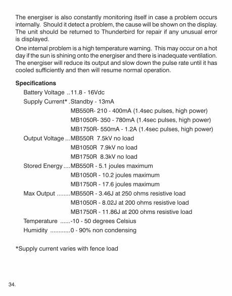
Specifications
Battery Voltage ..11.8 - 16Vdc
Supply Current* .Standby - 13mA
MB550R- 210 - 400mA (1.4sec pulses, high power)
MB1050R- 350 - 780mA (1.4sec pulses, high power)
MB1750R- 550mA - 1.2A (1.4sec pulses, high power)
Output Voltage ...MB550R 7.5kV no load
MB1050R 7.9kV no load
MB1750R 8.3kV no load
Stored Energy ....MB550R - 5.1 joules maximum
MB1050R - 10.2 joules maximum
MB1750R - 17.6 joules maximum
Max Output ........MB550R - 3.46J at 250 ohms resistive load
MB1050R - 8.02J at 200 ohms resistive load
MB1750R - 11.86J at 200 ohms resistive load
Temperature ......-10 - 50 degrees Celsius
Humidity ............0 - 90% non condensing
*Supply current varies with fence load

35.
S15B and S25B - Portable Solar Powered Energisers
Important! Read the warnings, regulations and installation instructions earlier in this book before installing and operating this energiser.
The Thunderbird portable solar range are a versatile tool for controlling stock around your property. They can be installed in minutes in any location, and use the power from the sun for continuous operation.
The S15B and S25B have an internal sealed lead acid battery for power storage.
The internal battery has a 12 month warranty. The battery has a 4 - 5 year life if it is properly cared for. Do not store the energiser for extended periods out of the sunlight. The battery will fail within a month or so if it’s stored in a discharged state.
Mounting - These energisers have a slot in the rear which has been designed to slide onto a steel ‘Y’ or ‘T’ post for an easy set up. Never sit or lay the energiser on the ground to operate, as this could void the warranty. Position the energiser so that the solar panel faces the equator, and make sure that shadows cannot cover the panel at any time during the day. Ensure that it’s out of the reach of animals and that mechanical damage cannot occur. The energiser should be mounted in the middle of the fence for the best effect.
Refer to the Installation section earlier in this book for fence construction and earthing.
NOTE: Hot tape and polywire can be used effectively for lengths up to 400m from the energiser. Thundertape and Thundercord can be used on runs up to 1km in any direction. Use galvanised fencing wire for longer distances. Refer to the poly tape section in Thunderbird’s product brochure.
This energiser is supplied with leads for connecting the energiser to the fence. Make sure the energiser is switched off before connecting it up. Connect the green earth lead to the green terminal and then to the fence earth. Connect

36.
the red fence lead to the red terminal and then to the fence live wire. The energiser is now ready to operate.
Operation - These energisers have 3 control buttons and 3 LEDs for control and indication. They can be selected to operate at either high or low power level.
Press the “high” key for normal operation, and the high power LED will start flashing once per pulse. Press the “low” key if you want to operate the unit in low power level, and the low power LED will start flashing once per pulse.
The low power level is intended to be used during extended periods of cloudy weather, where there is little sunshine to keep the internal battery charged. However, the energiser should operate in high power for approximately 10 days before the battery gets low, even with little or no sun.
Press the “off” key to turn the energiser off. The battery will continue to be charged from the solar panel when the energiser is off.
The low battery LED will start flashing if the battery voltage falls below approximately 12.0V, and the output power will be reduced. It will stay lit continuously if the battery voltage falls below approximately 11.4V, and the energiser will stop pulsing. This is to protect the battery.
The energiser detects the amount of sunlight that is received, and will slow the pulse rate down during the night to help conserve the battery.
It also has self testing built in. Should a fault occur, multiple flashes of the pulse LED will be seen at pulse rate intervals. Return the unit for repair if this ever occurs.
Solar Power - The solar range of energisers design has been based upon the energiser receiving an average 5 hours of sunlight a day in winter in the more southerly half of Australia. Cloudy weather will reduce this exposure time.
Solar radiation is measured in megajoules per square metre. The solar radiation varies greatly over the continent of Australia, from the tropical north to the very temperate south of Tasmania. The seasons also affect the amount of radiation. The 2 diagrams on page 41 show the radiation pattern.
As can be seen, there is also a dramatic difference in radiation between
37.
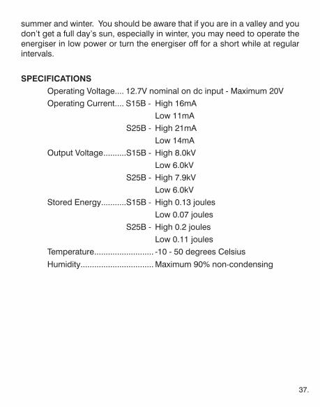
summer and winter. You should be aware that if you are in a valley and you don’t get a full day’s sun, especially in winter, you may need to operate the energiser in low power or turn the energiser off for a short while at regular intervals.
SPECIFICATIONS Operating Voltage .... 12.7V nominal on dc input - Maximum 20V Operating Current .... S15B - High 16mA Low 11mA S25B - High 21mA Low 14mA Output Voltage ..........S15B - High 8.0kV Low 6.0kV S25B - High 7.9kV Low 6.0kV Stored Energy...........S15B - High 0.13 joules Low 0.07 joules S25B - High 0.2 joules Low 0.11 joules Temperature .......................... -10 - 50 degrees Celsius
Humidity................................ Maximum 90% non-condensing

38.
S20B, S40B, S65B, S70, S150 - Solar Powered Energisers
Important! Read the warnings, regulations and installation instructions earlier in this book before installing and operating this energiser.
The Thunderbird portable solar range are a versatile tool for controlling stock around your property. They can be installed in minutes in any location, and use the power from the sun for continuous operation.
The S40B and S65B have an internal sealed lead acid battery for power storage. The S70 and S150 require an external battery, preferably a deep cycle or solar battery. Normal car batteries have a very short life if they are regularly discharged below 50% capacity.
Minimum battery sizes for the S70 and S150 are:
S70 - 20AH (amp hour)
S150 - 30AH
The S20B, S40B and S65B come with a 240Vac plug pack so that the internal battery can be recharged if there are extended periods of cloudy weather. Never attempt to charge the internal battery with a normal battery charger. It will destroy the battery and void your warranty.
The internal battery has a 12 month warranty. The battery has a 4 - 5 year life if it is properly cared for. Do not store the energiser for extended periods out of the sunlight. The battery will fail within a month or so if it’s stored in a discharged state.
Mounting - These energisers have a slot in the rear which has been designed to slide onto a steel ‘Y’ or ‘T’ post for an easy set up. Never sit or lay the energiser on the ground to operate, as this could void the warranty. Position the energiser so that the solar panel faces the equator, and make sure that shadows cannot cover the panel at any time during the day. Ensure that it’s out of the reach of animals and that mechanical damage cannot occur. The energiser should be mounted in the middle of the fence for the best effect.
39.
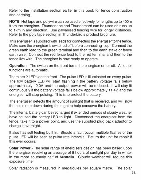
Refer to the Installation section earlier in this book for fence construction and earthing.
NOTE: Hot tape and polywire can be used effectively for lengths up to 400m from the energiser. Thundertape and Thundercord can be used on runs up to 1km in any direction. Use galvanised fencing wire for longer distances. Refer to the poly tape section in Thunderbird’s product brochure.
This energiser is supplied with leads for connecting the energiser to the fence. Make sure the energiser is switched off before connecting it up. Connect the green earth lead to the green terminal and then to the earth stake or fence earth wire. Connect the red fence lead to the red terminal and then to the fence live wire. The energiser is now ready to operate.
Operation - The switch on the front turns the energiser on or off. All other functions are automatic.
There are 2 LEDs on the front. The pulse LED is illuminated on every pulse. The low battery LED will start flashing if the battery voltage falls below approximately 12.0V, and the output power will be reduced. It will stay lit continuously if the battery voltage falls below approximately 11.4V, and the energiser will stop pulsing. This is to protect the battery.
The energiser detects the amount of sunlight that is received, and will slow the pulse rate down during the night to help conserve the battery.
The internal battery can be recharged if extended periods of cloudy weather have caused the battery LED to light. Disconnect the energiser from the fence, take it to a power point, and use the supplied plug pack adaptor to charge it overnight.
It also has self testing built in. Should a fault occur, multiple flashes of the pulse LED will be seen at pulse rate intervals. Return the unit for repair if this ever occurs.
Solar Power - The solar range of energisers design has been based upon the energiser receiving an average of 5 hours of sunlight per day in winter in the more southerly half of Australia. Cloudy weather will reduce this exposure time.
Solar radiation is measured in megajoules per square metre. The solar
40.
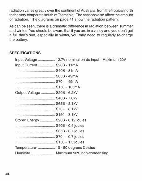
radiation varies greatly over the continent of Australia, from the tropical north to the very temperate south of Tasmania. The seasons also affect the amount of radiation. The diagrams on page 41 show the radiation pattern.
As can be seen, there is a dramatic difference in radiation between summer and winter. You should be aware that if you are in a valley and you don’t get a full day’s sun, especially in winter, you may need to regularly re-charge the battery.
SPECIFICATIONS
Input Voltage ................. 12.7V nominal on dc input - Maximum 20VInput Current ................. S20B - 11mA ....................................... S40B - 31mA ....................................... S65B - 49mA ....................................... S70 - 49mA ....................................... S150 - 105mAOutput Voltage .............. S20B - 6.2kV ....................................... S40B - 7.8kV ....................................... S65B - 8.1kV ....................................... S70 - 8.1kV ....................................... S150 - 8.1kVStored Energy ............... S20B - 0.12 joules ....................................... S40B - 0.4 joules ....................................... S65B - 0.7 joules ....................................... S70 - 0.7 joules ....................................... S150 - 1.5 joulesTemperature- ................. 10 - 50 degrees CelsiusHumidity ........................ Maximum 90% non-condensing

41.
42.
Remote ControlAll of the Thunderbird energisers that have an “R” as a suffix of the model number can be controlled by an optional Thunderbird remote control. The remote control allows you to turn the pulsing on and off anywhere along the fence line.
The remote control can be security coded if desired. All remote controls leaving the factory have the same security code, and all energisers that haven’t had a security code change will receive the remote signal. However the code may be changed.
Operation - Connect the remote to the fence by clipping the earth lead to an earthed wire in the fence, then place the metal clip on the back of the remote onto the live wire. Hold the remote button down for a minimum of 2.5 seconds, or until a click is heard. The reason for the delay is that the remote listens for more than the maximum pulse period time to make sure that the energiser is not already pulsing. If it is, a signal is sent immediately after the pulse.
Briefly pressing and releasing a button on the remote will power the remote, and the pulse LED will flash at every fence pulse while it’s connected to the fence. From this you can ascertain whether the energiser is working.
If the pulse LED on the remote control flashes rapidly, it is indicating that the battery is starting to become flat. Briefly releasing the button and pressing it again will allow a transmission to occur if there is enough power left in the battery.
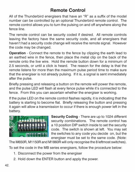
Security Coding - There are up to 1024 different security combinations. The remote control has a 10 position DIP switch inside to set the security code. The switch is shown at left. You may set the switches to any code you decide on, but the energiser must be set to the same code. (Note:
The M650R, M1150R and M1860R will only recognise the 8 leftmost switches).
To set the code in the MB series energisers, follow the procedure below:
1. Disconnect the power from the energiser
2. Hold down the ENTER button and apply the power.

43.
Keep holding the ENTER button down until the display reads “Change remote device ID?”. Release the ENTER button and press YES.
3. Starting from position 1 on the remote DIP switch, use the up and down arrows to set the first position (1 is on, 0 is off). Press ENTER.
4. Repeat step 3 until all 10 positions of the DIP switch are entered, then exit this mode.
Changing the security code in an “M” series Thunderbird energiser must be done by a person qualified to work on 240Vac equipment. To change the code:
1. Disconnect the energiser from the mains and the fence.
2. Remove the back from the energiser.
3. On the upper right hand side of the PCB you will see a DIP switch similar to the remote. Set the switches to the same as the remote, top most switch in the energiser matches the left switch in the remote.
4. Replace the back on the energiser.
Multiple remote controls may be used on the energiser, but each remote must have the switches in the same position.
Interference - A signal will also be sent immediately after any induced pulse from a neighbouring electric fence. These induced pulses can cause 2 transmissions from the remote in one pulse period, which can cause problems with communication. Induced pulses are most commonly caused by 2 electric fences powered by different energisers running next to each other for some distance. A solution is to fit a resistive load to the fence near the source of the problem to eliminate these induced pulses.
Battery - The remote uses a 9V battery. It must be an alkaline type battery for the energiser to operate, because the remote draws a large amount of current for a very brief period. A normal carbon-zinc battery cannot supply the required current. A good quality alkaline battery should last for 150 - 200 activations.
44.
Trouble Shooting
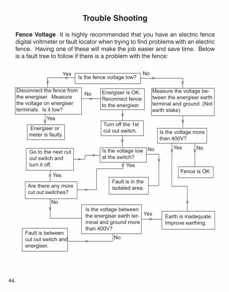
Fence Voltage - It is highly recommended that you have an electric fence digital voltmeter or fault locator when trying to find problems with an electric fence. Having one of these will make the job easier and save time. Below is a fault tree to follow if there is a problem with the fence:
Is the fence voltage low?Yes No
Disconnect the fence from the energiser. Measure the voltage on energiser terminals. Is it low?
Energiser or meter is faulty.
Energiser is OK. Reconnect fence to the energiser.
Measure the voltage be-tween the energiser earth terminal and ground. (Not earth stake)
Is the voltage more than 400V?
Fence is OK
Turn off the 1st cut out switch.
Are there any more cut out switches?
Is the voltage between the energiser earth ter-minal and ground more than 400V?
Earth is inadequate. Improve earthing.
Go to the next cut out switch and turn it off.
Fault is between cut out switch and energiser.
Is the voltage low at the switch?
Fault is in the isolated area.
Yes
No
NoYes
Yes
Yes
Yes
No
No
No
45.
Remote Control - The fence must be well constructed, with all wire joins to be done with joint clamps in order for the remote control to work effectively. If the remote control doesn’t work, check the following:
1. Check that the security codes match. 2. Make sure that the earth clip is connected to the fence earth. 3. Make sure that the energiser is either in standby or running. 4. Check that the fence and joins to the energiser are OK. 5. Check that the section of fence you are standing at is not isolated by a cut out switch. 6. Move at least 100m towards the energiser from a short. 7. Replace the battery. The battery must be an alkaline type.
TV or Radio Interference - Interference to TV or radio from an electric fence is always caused by an arc or spark somewhere along the fence. It can be on the high voltage section or can be caused by a poor earth contact. It can be a tedious process to find the problem. Common causes are loose connections, live wire close to an earth, or insulator breaking down. All energisers are designed not to cause interference. Some tips are:
1. Check that all connections along the fence, including those on the energiser, are tight.
2. Go along the fence and check that there are no wires close together.
3. If all looks OK, take a radio tuned to a weak AM station, and go along the fence. Loudest interference will indicate that the problem is nearby.
4. Failing that, go along the fence and look carefully on a dark, moonless night. It is possible to see a faint bluish or purplish glow where the spark is occurring. Don’t forget to check earth points as well.
46.
Phone or Internet Interference - There are 2 main causes of interference onto phone lines. One is the same as TV interference, refer to that section on the previous page. The other is induced voltage into the phone line.
Induced voltage occurs when there is a relatively long section of fence that is conducting a lot of current and running close to and in parallel with an underground or above ground phone line. Reducing the current in the electric fence will solve this. Here’s how:
1. The main fence feeder wire for the property must be at least 100m from any underground or above ground phone line.
2. Make sure any fence earth is more than 10m from any phone earth.
3. Check for shorts or heavy loads on the fence.
4. If an electric fence must run close to a phone line, place an end strain insulator in the middle of the fence section running close to the phone line, and feed the fence voltage from both ends. This will limit the current flow in the fence.

47.
WARRANTYTHUNDERBIRDElectric Fence Systems
Thunderbird warrant all electric fence systems against defective workmanship and faulty materials for 2 years, plus a warranty for 6 months against lightning damage, from the date of purchase. A 12 month warranty applies to batteries in solar energisers. We undertake, at our option, to replace or repair free of charge each product, or part thereof, on condition that it is returned to an authorised agent or our factory freight prepaid, and found on examination to be suffering from material or constructional defect. We cannot be held responsible for any repair other than those carried out by us or our authorised agent.
A photocopy of your proof of purchase and a request for warranty must also be returned with the item.
This warranty is void if the product is subject to improper use or handling, incorrect power input voltage, damage through contact with chemicals, flooding, fire, explosion, excessive heat, lightning strikes outside the lightning warranty period, insect damage and moisture damage. Damage to external wiring and wear and tear are excluded from warranty.
For your records:
Model No.: ......................................................................................................
Serial No.: .......................................................................................................
Date of Purchase: ...........................................................................................
Place of Purchase: .........................................................................................
Receipt No.: ....................................................................................................

Country Electronics Pty LtdABN 38 003 806 040
11 Industrial Avenue PO Box 391Mudgee NSW 2850 Mudgee NSW 2850
Phone: 02 63723600 Web: www.thunderbird.net.auFax: 02 63722597 Email: [email protected]