ferrite microwave technologies circulators, isolators &...
TRANSCRIPT

F e r r i t e M i c r o w a v e T e c h n o l o g i e s
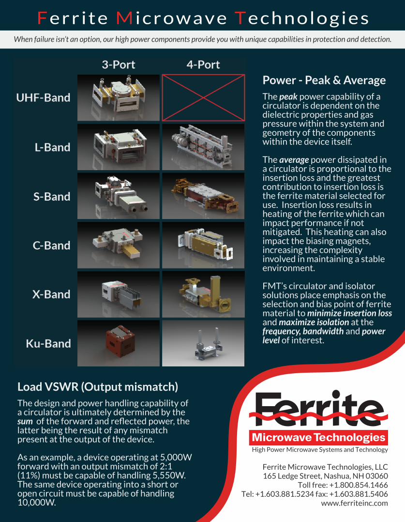
3-Port Junction- Waveguide WR28 to WR2300- Coaxial SMA to 9.1875”- Fixed footprint driven by frequency- Extremely low insertion loss
3-Port Junction
Circulators, Isolators& Duplexers
Fixed (MHz)Frequencies
CommonBands (MHz)
56 1,200-1,40060 1,215-1,415
202 2,100-2,400352 2,700-2,900500 2,700-3,100650 3,100-3,500805 4,900-5,100915 5,400-5,900
1,300 6,300-6,8001,497 7,500-8,5002,100 8,500-9,6002,450 9,500-10,5002,856
14,000-14,8002,998
17,300-18,1005,712
11,900-13,200
5,800 15,500-17,500
9,300
4-Port Differential Phase Shift
4-Port Differential Phase Shift- Waveguide WR28 to WR650- Footprint can be increased for ultra-high average power applications- Extremely high isolation
18,100 - 19,600
S-Band
F e r r i t e M i c r o w a v e T e c h n o l o g i e s
Ferrite Microwave Technologies, LLC165 Ledge Street, Nashua, NH 03060
Toll free: +1.800.854.1466Tel: +1.603.881.5234 fax: +1.603.881.5406
www.ferriteinc.com
High Power Microwave Systems and Technology
When failure isn’t an option, our high power components provide you with unique capabilities in protection and detection.
Load VSWR (Output mismatch)The design and power handling capability of a circulator is ultimately determined by the sum of the forward and reflected power, the latter being the result of any mismatch present at the output of the device.
As an example, a device operating at 5,000W forward with an output mismatch of 2:1 (11%) must be capable of handling 5,550W. The same device operating into a short or open circuit must be capable of handling 10,000W.
Power - Peak & AverageThe peak power capability of a circulator is dependent on the dielectric properties and gas pressure within the system and geometry of the components within the device itself. The average power dissipated in a circulator is proportional to the insertion loss and the greatest contribution to insertion loss is the ferrite material selected for use. Insertion loss results in heating of the ferrite which can impact performance if not mitigated. This heating can also impact the biasing magnets, increasing the complexity involved in maintaining a stable environment.
FMT’s circulator and isolator solutions place emphasis on the selection and bias point of ferrite material to minimize insertion loss and maximize isolation at the frequency, bandwidth and power level of interest.