ferry terminals and s04all craft o thin ... design manual dm-25.5 design criteria ferry terminals...
TRANSCRIPT

AD-AII 526 NAVAL FACILITIES ENINERING COMA ALEXANDRhA VA F/9 13/13
FERRY TERMINALS AND S04ALL CRAFT O THIN FACILITIES. DESISN MAN--ETC(U)p .JUL 81UNCLASSIFIED NAVFAC-ON-2S.5 NL
mrh///l/l///
hmmmmhhhhhmhmhIIIIIIIIIIIIIIIIIIIIIIIIIIII
lllllllllllllI

UnclassifiedSECURITY CLASSIFICATION OF THIS PAGE (When Data Entered)
REPORT DOCUMENTATION PAGE READ I 1s TION: D-25.5BEFORE CO MLETING ORM
i I. REPORT NUMBER j2. GOVT ACCESSION NO. 3. RECIPIENT'S C ALMU R
IDM-25.5 p,4( zh
4. TITLE (and Subtitle) 5. TYPE OF REP iERIOD COVERED
NAVFAC Design Manual DM- 25 .5 Design Criteria
Ferry Terminals and Small Craft Berthing Final
Facilities 6. PERFORMING ORG. REPORT NUMBER
F DM-25.51'7. AUTHOR(s) 6. CONTRACT OR GRANT NUMBER(s)
reaq Naval Facilities Engineering Command
t 200 Stovall Street
Alexandria, VA 22332 (Code 0453)9. PERFORMING ORGANIZATION NAME AND ADDRESS 10. PROGRAM ELEMENT. PROJECT. TASK
Naval Facilities Engineering Command AREA & WORK UNIT NUMBERS
200 Stovall Street Engineering and DesignAlexandria, VA 22332
Al. CONTROLLING OFFICE NAME AND ADDRESS 12. REPORT DATE
Naval Facilities Engineering Command (Code:0432) July 1981200 Stovall Street 1s. NUMBEROF PAGESAlexandria, VA 22332 100
14. MONITORING AGENCY NAME & ADDRESS(If different from Controlling Office) IS. SECURITY CLASS. (of this report)
Unclassified
1Sa. DECL ASSI FICATION/DOWNGRADINGSCHEDULE
IS. DISTRIBUTION STATEMENT (of thisReport)
Unclassified/Unlimited
17. DISTRIBUTION STATEMENT (of the abstract entered In Block 20, If different from Report)
Unclassified/Unlimited
... SEP 2 3 1982
IS. SUPPLEMENTARY NOTES " 18
I,, A-J
19. KEY WORDS (Continue on reverse side if necessary and identify by block number)
S Berthing system design; degaussing and deperming facilities; entrance channeldesign; environmental factors; environmental protection; ferry terminals;other sheltered basin structures; protective structure design; siting; smallcraft berthing facilities; support facilities design.
A ABSTRACT (Continue on reverse tide It necessary and Identify by block number)
asic criteria for design of ferry terminals, small-craft berthing facilities,and degaussing and deperming facilities are presented herein for use by ex-perienced port, cdastal,' and construction engineers and constructors. Thecontents cover general siting, layout, and environmental considerations andrequirements, specific criteria for design of ferry terminals, small-craftberthing systems, support facilities, protective structures and features, andmajor design problems associated therewith
DD JAN7, 1473 EDITION OF I NOV65 IS OBSOLETE
I Iml I -- ... . .. • .... .. .

NAVFAC DM-m5.5JULY 1981
T OF APPROVED FOR PUBLIC RELEASE
FERRY TERMINALSAND SMALL CRAFTBERTHING FACILITIES
DESIGN MANUAL 25.5
I F T-hi dcrvm--n-thra - been raoppiove4d
f- ~ rrlo s cid ,ale; its
DEPARTMENT OF THE NAVY ANAVAL FACILITIES ENGINEERING COMMAND200 STOVALL STREETALEXANDRIA VA. 2232 8 9 2
DISTRIBUTION: (1 copy each unless otherwise specified)
SNDL FF38 FT223A1 (COHMNAVFORAZORES only) F2 (Balboa, Harold Holt, Ne FT624J1 Makri, Thurso, Stockton, FT13 (Lass Millington) - &27G and Ponce only) FTI839B 7G3 (Cheltenham and East FT19 (San Diego only)39C1 Machias only) FT2239E 7G6 (Wahiawa and Norfolk only) FT27 (Idaho Falls only) I42A3 733 (Beaufort only) FT2845B F6 (Bethesda only) FT3149 7118 (Cairo only) FT37
51A 7N25 (Philadelphia, Portsmouth FT55 I51B1 VA, Camp Lejeune, Oakland, FT6451B3 Newport, Great Lakes, and FT73B2A (JCS, NSA, DIA, and DNA Long Beach only) FT74A (MIT and Texas only)
only) FJ5 FT74B (California, Illinois,B5 (USCG only) F7A6A1 Rensselaer, Georgia TechC34 (Holy Loch, Souda Bay only) FKA6A2 only)C37D (Port Hueneme only) FKA6A3A FT78 (2 copies)E3A FK.A6A3B V2FA6 (Bermuda, Brunswick, Cecil FKA6A9 V3
Field, Key West, FKA6AI2 V5Jacksonville, Virginia FKA6AI5 (Code 521) V8Beach only) FKA6Al6 V12
FA7 (Guantanamo, Keflavik, FKA9 V14Brooklyn, Panama Canal, FPlS V15Mayport, Roosevelt Roads Ff19 V16 (less Camp Smith)only) FKl2 V17
FAIO F13 V23FA18 F15 (Philadelphia only) V25FA23 (Antigua, Brawdy, Buxton, FKNI (West and Lent only (85
Lewes only) copies each)) Copy to: (One copy each unlessFA32 FKll (South and North only (50 otherwise indicated)FB6 copies each))F37 (Alameda, Fallon, Lemoore, FKNI (Pac only, 25 copies each) 21A
Oak Harbor, Miramar, North F11 (Ches only, 25 copies A2A (ONR only)Island, Moffet Field only) each) A3
FBI0 (Adak, Midway only) FKNI (Ches, FPO- only) A4AF321 FKN2 A5F331 (Guam only) FN13 (6 copies each) A6 (Code LFF) VF334 (Kadena, Sasebo only) FIN5 (5 copies each) C7 (Brazil and Chile only)FB36 (Big Sur, Coos Head, FIJ8 FDI
Ferndale, and Pacific F10 FEIBeach only) FKPlI (less Concord) FG1
F341 FPI (Concord only, 3 copies) FKAIAFB48 FIPIE FKAIB (2 copies)7C3 (London only) FKPIJ FAIC (Code 043 - 50 copies)7C4 (Sigonella only) KPlM FAIF7C5 lKP3A 1112 (Port Hueneme (Code 156)7C7 7rP7 only)FC12 lIP8 FlFD2 FIPIlF22 1KQ 3 Additional copies are available734 (Adak, gdsell, Hansa, 7111lA from: .1
Galeta Island, Homestead, F7113 (2 copies)Winter Harbor, Sabana 71R2A (Dallas only) Comanding OfficerSeca, and Sonoma only) FIR3A Naval Publications and
FFI (Washington only) lmR3R Forms Center IFF5 FR43 5801 Tabor Avenue
FF6 l115 Philadelphia, PA 19120FF19 (New Orleans, Seattle only) 1M171 (3 copies)
113l14FTI
ABSTRACT
Basic criteria for design of ferry terminals, small-craft berthingfacilities, and degaussing and deperming facilities are presentedherein for use by experienced port, coastal, and construction engi-neers and constructors. The contents cover general siting, layout,and environmental considerations and requirements, specific criteriafor design of ferry terminals, small-craft berthing systems, support
I facilities, protective structures and features, and major designproblems associated therewith.
III
I
II
" ji
1 25.5-111*-
6>PPElrE
I FOREWORD
This design manual is one of a series developed from an evaluationof facilities in the shore establishment, from surveys of theavailability of new materials and construction methods, and fromj selection of the best design practices of the Naval FacilitiesEngineering Command, other Government agencies, and the privatesector. This manual uses, to the maximum extent feasible, nationalprofessional society, association, and institute standards inaccordance with NAVFACENGCOM policy. Deviations from these criteriashould not be made without prior approval of NAVFACENGCOM Head-quarters (Code 04).
Design cannot remain static any more than can the naval functionsit serves or the technologies it uses. Accordingly, recommenda-tions for improvement are encouraged from within the Navy and fromthe private sector and should be furnished to NAVFACENGCOM Head-quarters (Code 04). As the design manuals are revised, they arebeing restructured. A chapter or a combination of chapters willbe issued as a separate design manual for ready reference tospecific criteria.
This publication is certified as an official publication of theNaval Facilities Engineering Command and has been reviewed andapproved in accordance with the SECNAVINST 5600.16.
Rea dia EUS. NavyCommander
Naval Facilities Engineering Command
I2.
i
25,5-v
I
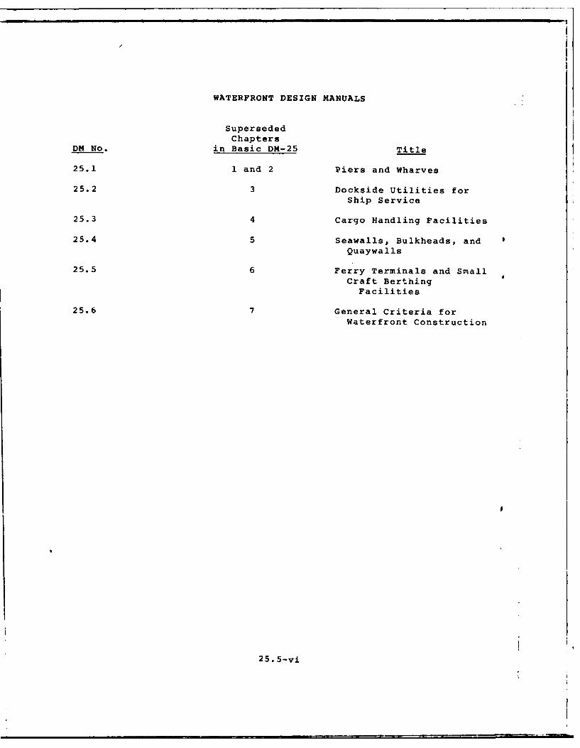
WATERFRONT DESIGN MANUALS
SupersededChapters
DM No. in Basic DM-25 Title
25.1 1 and 2 Piers and Wharves
25.2 3 Dockside Utilities forShip Service
25.3 4 Cargo Handling Facilities
25.4 5 Seawalls, Bulkheads, and 0Quaywalls
25.5 6 Ferry Terminals and SmallCraft BerthingFacilities
25.6 7 General Criteria forWaterfront Construction
I5
25. 5-vi

I CONTENTS
I FERRY TERMINALS AND SMALL CRAFT BERTHING FACILITIES
Section 1. INTRODUCTION Pg
1. Scope . .. .. .. .. .. ... .. .. ... .... 25.5-1
2. Cancellation............................ 25.5-13. Related Criteria . . . . ................ , *25.5-1I Section 2. FERRY TERMINALS1. Ferry Terminal......................25.5-22. slips............................25.5-2
3 3. Fender Racks.........................25.5-2
a. Design Loadings........................25.5-2b. Construction Details..................25.5-2
- 4, Feiry Transfer Bridges ................................ 25,5-5* a. Operation.........................25.5-5
b. Appurtenances. ....................... 25.5-5Section 3. SMALL CRAFT BERTHING FACILIISPart 1. Planning and Layout CriteriaI 1. Siting....................... ....... 25.5-5L
a. Berthing Craft . . . .. .. .. .. .. ...... 25.5-5
b.* Ramps.................................25.5-7c. Boat Fueling Docks....................25.5-7do Dr Strg . . . .. .. .. .. .. ... ... 25.5-7
so oatRepair . . . . . . .. .. . . .. ... ... 25.5-7
f.Harbor Administration.......................25.5-7
g. Vehicular Parking.....................25.5-72. Space Req~uirements.....................25o5-7
a. Berthing Basins . . .. .. .o. .. .. .. ..... 25.5-7bLand Area. ........... ... ......... 25.5-7
c. Finger Width . . o. . .. .. .. .. .. .. .. 25.5-7
d * Water Area. ........................................... 25.5-9je. Launching Ramp or Hoist.......................25.5-9
f . Parking Lot . . . . . o. . . . .. .. .. ..... 2!.5-9
go Harbor Service Facilities.......... ........... 25.5-93. Berthing Basin Depths. .o. ... .. .. ..... 25.5-9Ia.* Factors. .. ..... .. ... .. .. ....... 25.5-9
b. Basis . . . . . . . . .0. .. .. .. .. .. .... 25.5-9
*c. Minimum Depths . . . . .. .. .. .. .. .. .... 25.5-93 4. Entrance Channel and Structures . . . . . . . . . . 25.5-9a. Channel Alignment . . .. .. .. .. .. ....... 25.5-9b. Channel Width . . . o . . .. .. .. o.........25.5-10
C. Channel Depth . . . . . . . . . . o . .. .. .. .. 2545-10
*d. Jetties. . o . . . . . . 0 . . .. .. .. .. .... 25.5-10
e. Other Protection . . . . . . . . . . . . .... 25.5-10
5. Turning Area . . o . o - o . . . . . . 25.5-10I Part 2. Environmental Siting Factors1. Local Weather Factors. o. ... .... . . . . . 25.5-l0
a. Precipitation. *. o . . . . . . 0 . 0 . . . . . . 25.5-10
do Windg . . . . o . . . o . . . . . . . . . 0 . . . 25o5-12
25. 5-vii
CONTENTS
Page
2. Wave-related Factors.....................25.5-12a.* Swell.................................25.5-12b.* Surge.....................................25.5-12C.* Tides...................................25.5-12
3. Water Area Shoaling Factors.....................25.5-13a. Littoral Drift............................25.5-13b. River Discharge............................25.5-13C. Nearby Water Area Structures.................25.5-15d. Redistribution of Bottom Materials..........25.5-154. Geological Factors........................25.5-15
a. Basin Excavation...........................25.5-15b. Foundations................................25.5-15C. Material Sources...........................25.5-15d. Seismic Activity...........................25.5-16
5. Impact on Environment.......................25.5-16Part 3. Design, Criteria for the Berthing System1. Slip and Berth Clearances...................25.5-16
a. Berth Clearance..........................25.5-16b. Finger Piers...........................25.5-16C. Fairway widths............................25.5-16d. mooring Layouts............................25.5-17e. Slip and Berthing Arrangements..............25.5-17f. Dimensional Criteria and Typical Details.......25.5-19
2. Fixed-versus-Floating Pier System...............25.5-19a. General Factors....................................25.5-19b. Selection Criteria......................25.5-23
3. Fixed-Pier Berthing Systems......................25.5-23a. General Features.........................25.5-23b. Vertical Loading.........................25.5-24c. Other Design Criteria.........................25.4-24d. Typical Construction.........................25.4-24
4. Floating-Pier Berthing Systems....... .. 25.5-24a. General Considerations......................25.5-24b. Flotation Materials..........................25.5-24c. Deck Materials and Surface..................25.5-27d. Deck Framing and Float Connections . . . * 25.5-31e. Vertical Loading and Deck Levels . . . . * 25.5-33f. Typical Construction................ . . 25,5-33
5. Lateral Loading ............ 9 . * 0 25,5-33a. Loading....................................... . . * 25.5-33b. Analysis.............. . .. .. . . . . . . * 25.5-37
6. Anchorage Systems;............ . , 25.5-37a. Selection Criteria............ 0 , 25.5-37b.* Systems....... ...... . . .. .. .. ... . . . 25.5-37
7. Approach Piers and Gangways. .. ....... 25.5-40a. General Criteria .. .......... . . . . * 25,5-40
Part 4. Design Criteria for Other Sheltered Basin Structures1. Perimeter Stabilization. ....... , . . * 9 9 * * 25.5-43
a. objectives............... . . . . . 25.5-43b. Structures . . ...... ... ... ...... .............. . . . . 25,5-43
25. 5-viii

CONTENTS
Page
2. Perimeter Beach......................25.5-45a. Slopes....................................25.5-45b. Profile...................................25.5-45C. Design Details.............................25.5-45
3. Revetted Slopeo................................25.5-45a. Revetments....................................25o5-45b. Armoring...................................25.5-45c. Filtering Devices..............................25.5-46d.o Profile.................................25.5-46e. Design Details............................25.5-46
4. Gabioned Slope.............................25.5-46a. Use.........................................25.5-46j b. Construction.................................25.5-46c. Typical Details...........................25.5-46
5. Vertical Bulkhead............................25.5-49a. Use Criteria.....................................25.5-49b. Types..................................25o5-49C. Design Details...............................25o5-49d. General Considerations......................25.5-49
Part 5. Design Criteria for Entrance Channel and ProtectiveStructures
1. Entrance Channel..............................25.5-50a. Location.......................................25.5-50b. Design Criteria..........................25.5-50C. Construction....................................25.5-51d. Maintenance Dredging.........................25.5-51
2. Breakwaters..............................25.5-51a. Purpose....................................25.5-51b. Design Data...................................25.5-51C. Breakwater Positioning....................25.5-52d. Design Factors..............................25.5-52e.* Types ................................. 25.5-52
f. Rubble-Mound Construction....................25.5-54g. Design Details................................25.5-57
3.* Groins..........................25.5-57a. Purpose..........................25.5-57b. Types . 1...........25.5-58c. Design Criteria....................25.5-58
4.* Jetties..........................25.5-58a. Purpose.............................25.5-58b. Types...........................25.5-58C.* Details .. ................ ..... 25o5-58
5. Wave and Surge Dissipators . *.. .. .. .... 25.5-58a. Purpose.................. .. 0* 25.5-58b. Typical Devices . . . . ... .. .. .. *.... 25.5-58
6. Bank Protection .................. 25.5-61a. Protection. ........ . . . . . . .* 25.5-61b. Details . . . . .. .. .. .. . ... . . .0.025o5-61
7. River Protection . . . . . . * . . ... .. 25o5-61
a. Current Deflector Placed Upstream . . . . .. o 25o5-61beShallow Basin Excavated into the Riverbank ... 25.5-61
25. 5-ix

CONTENTS
Page
8. Floating Wave Attenuators.......................25.5-61Part 6. Design Criteria for Support Facilities1. Utilities......................................25.5-642. Locker Boxes and Fire Equipment....................25.5-64
a. Locker Boxes..............................25.5-64b. Firefighting Equipment........................25.5-64
3. Fuel Docks and Pumpout Stations..................25.5-64a. Fuel Docks..................................25.5-64b. Pumpout Stations.............................25.5-65
4. Cleats and Fenders..........................25.5-65a. General......................................25.5-65b. Cleats..................................25.5-65C. Fenders...................................25.5-65
5. Launching Hoists, Elevators, and Ways:............25.5-66a. Types.......................................25.5-66b. General Characteristics...................25.5-67C. Functional Characteristics of Different Types. 25.5-67d. Typical Facility...............................25.5-68
6. Launching Ramps..............................25.5-68a. Slope..........................................25.5-68b. Surface......................................25.5-68C. Approach......................................25.5-68d. Bottom......................................25.5-68e. General Features...............................25.5-68f. Typical Layout ............................... 25.5-70
7. Support Buildings and Ancillary*Structures . 25.5-70a. Administration Building......................25.5-70bo Maintenance Building and Yard for Storage ....... 25.5-70C. Boat Repair Facility.......................... 25.5-73d. Hardware Supply Store (Optional)................ 25.5-73e. Transient Housing Facilities.....................25.5-73f. Road and Walkway System........................25.5-73g. Layout of Utilities..........................25.5-73h. Perimeter Fencing....................... . 25.5-73
8. Dry Storage..................................25.5-73a.* Purpose.....................................25.5-73b. Storage Criteria.............................25.5-73c. use Cr~iteria . . . o. .. .. .. .. .. .. . 25.5-73
9. cigns..................... . 25.5-75Part '7. Environmental Factors and Protection1.* Snow.............. . 0 . . . . . . ... 25.5-75
a.* Factors . . . . . . . .. .. .. .. .. .. .. 25.5-75b. Protection................... 25.5-75
2.* Ice .......... . . . .. .. .. . .... 25.5-75a. Protection......... .. .. .. . . . .. 25.5-75
3.* Hurricanes. ....... . .0 . .. 25.5-76a. Protection for Berthed Facilities ..... . 25.5-76b. Protection for Structural Components 25.5-76C. Design Provisions .. . . . . . . 25.5-76d. Emergency Precautions. 0 . . . .25.5-76
4. * oil Spills . . . . . . . . . . 0 . 25.5-77
25. 5-x
CONTENTS
Pagea
5. Floods ..... .. ....................... 25.5-77
a. Nature of Damage ...... ................. 25.5-77
b. Protection .......... ......... 25.5-77
Part 8. Summary of Common Design Problems1. Problems ......... ...................... 25.5-77
a. Ice, .......... ....................... 25.5-77
b. Corrosive Environment ................... 25.5-78
c. Fuel Dispensing, ...... . ................. 25.5-78
d. Floating-pier Systems ..... ............... 25.5-78
e. Shoaling of Channels and Basins ............ 25.5-78
f. Boat-wake Problems ...... ................ 25.5-78
Section 4. DEGAUSSING AND DEPERMING FACILITIES
1. Degaussing ....... .................... 25.5-78
2. Deperming ......... ..................... 25.5-79
3. Criteria ........ .................... . 25.5-79
4. Requirements ...... ................. .e 25.5-79
References . . .. . . . . . . . .. . . ...... .Reference-l
Glossary .......... ....................... .Glossary-l
25,5-xi
I
FIGURES
Figure Title Page
1. Ferry Terminal ........ .................. 25.5-32. Fender Rack ....................... 25.5-43. Ferry Transfer Bridge: .. ............... 25.5-64. Typical Layout of a Small-Craft Harbor ....... 25.5-85. Maintenance of Entrance to Off-River Basin
with Land-based Equipment (Schematic) ........ . 25.5-146. Typical Small-Craft Mooring Layouts ........ .. 25.5-187. Typical Berthing Arrangement .... ........... 25.5-208. Small-Craft Berthing Systems .... ........... 25.5-219. Dimensional Criteria for Berthed Craft ....... 25.5-22
10. Typical Fixed Finger Pier System ... ......... 25.5-2511. Various lypes of Floats ..... .............. 25.5-2812. Typical Foam Float with Concrete Deck ......... . 25.5-2913. Typical Water-ballasted Floating Dock ......... . 25.5-3014. Typical Deck Framing Systems and Float Connections 25.5-3415. Typical Floating Pier System .... .......... 25.5-3516. Windloading on Small-Craft Berthing System . . . 25.5-36
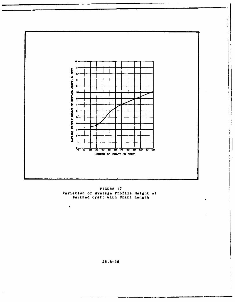
17. Variation of Average Profile Height of BerthedCraft with Craft Length ..... ............. 25.5-38
18. Sample Calculation for Windloading on a FloatingPier System ........ ................... 25.5-39
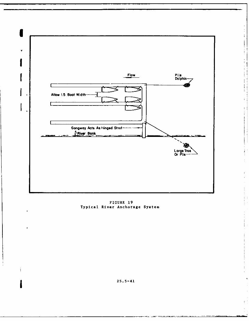
19. Typical River Anchorage System ... .......... 25.5-4120. Typical Use of Submerged Crossties to Strengthen
Covered Floating System ..... ............. 25.5-4221. Framing and Hinge Detail for Pipe-and-Rod Plate
Hinge for Heavy Gangway ..... ............. 25.5-4422. Typical Beach and Revetted Slope Profiles ..... . 25.5-4-/23. Typical Use of Gabions in Small-Craft Harbor
Construction ........ .................. 25.5-4824. Typical Rubble-Mound Breakwater ... .......... 25.5-5325. Typical Sheetpile Breakwater Construction ..... . 25.5-5526. Typical Swiss-cheese Perforated Breakwater
Construction ........ .................. 25.5-5627. Typical Rubble-Mound Groin Construction ... ...... 25.5-5928. Typical Sheetpile Jetty Construction ... ....... 25.5-6029. Typical Shallow Boat Basin Excavated into Riverbank
(Schematic) ......... .................. 25.5-6230. Typical Chained-Log Boom for Short-Period Wa. e
Attenuation ........ ................... 25.5-6331. Typical Hoist-Launching Facility with Dry Storage
Yard ...................... 25.5-6932. Layout of a Typical Launching Ramp Facility . .. 25.5-7133. Typical Maintenance Building and Yard Layout . . 25.5-7234. Typical Hinged Floating Launching Ramp Used for
Small Boats ........ ................... 25.5-74
25.5-xii
ACKNOWLEDGEMENTS
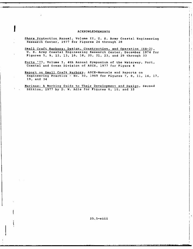
Shore Protection Manual, Volume II, U. S. Army Coastal EngineeringResearch Center, 1977 for Figures 24 through 28
Small Craft Harbors: Design, Construction, and Operation (SR-2),U. S. Army Coastal Engineering Research Center, December 1974 forFigures 5, 9, 12, 13, 16, 18, 20, 21, 23, and 29 through 33
Ports '77, Volume I, 4th Annual Symposium of the Waterway, Port,Coastal and Ocean Division of ASCE, 1977 for Figure 4
Report on Small Craft Harbors, ASCE-Manuals and Reports onEngineering Practice - No. 50, 1969 for Figures 7, 8, 11, 14, 17,19, and 34
Marinas: A Working Guide to Their Development and Design, SecondEdition, 1977 by D. W. Adie for Figures 6, 10, and 15
25.5-xiii
FERRY TERMINALS AND SMALL CRAFT BERTHING FACILITIES
Section 1. INTRODUCTION
1. SCOPE. This manual contains the descrii ion of salient featuresof ferry terminals. It includes planning, layout, and design cri-teria, requirements and problems associated with small craft berthingfacilities, and requirements for degaussing and deperming facilitiesas related to waterfront operations.
2. CANCELLATION. This publication entitled Ferry Terminals andSmall Craft Berthing Facilities, NAVFAC*DM-25.5, cancels and super-sedes provisions of Chapter 6 of NAVFAC DM-25 entitled WaterfrontOperational Facilities, and any of the following changes which relateto Chapter 6: Change 1 dated February 1972, Change 3 dated July
* 1973, Change 5 dated March 1974, Change 6 dated August 1974, andChange 7 dated June 1975. Changes 2 and 4 are cancelled items.
3. RELATED CRITERIA. For related criteria, refer to the NAVFACsources itemized below.
Subject Source
Piers and Wharves ................................ NAVFAC DM-25.1
General criteriaSeismic activity
Dockside Utilities for Ship Service ................. NAVFAC DM-25.2
Seawalls, Bulkheads, and Quaywalls ................... NAVFAC DM-25.4
General Criteria for Waterfront Construction..... NAVFAC DM-25.6
Structural Engineering: Steel Structures ........... NAVFAC DM-2.3Allowable stresses
Structural Engineering: Concrete Structures ....... NAVFAC DM-2.4Allowable stresses
Structural Engineering: Timber Structures ......... NAVFAC DM-2.5Allowable stresses
Electrical Engineering ........................... NAVFAC DM-4 SeriesLighting
Electric and fire alarm service
Civil Engineering: Drainage Systems ................ NAVFAC DM-5.3
Civil Engineering: Pavements .................... NAVFAC DM-5.4Allowable Stresses
25.5-1
Civil Engineering: Water Supply Sytems ............. NAVFAC DM-5.7
Fire Protection Engineering ...................... NAVFAC DM-8
Liquid Fueling and Dispensing Facilities ........... NAVFAC DM-22
Harbors .......................................... NAVFAC DM-26.1Tide data and aids to navigationBreakwaters and jetties
Coastal Protection ............................... NAVFAC DM-26.2Breakwaters, jetties, and groins
Mooring Design Physical and Empirical Data ....... NAVFAC DM-26.6Wind and current dataMooring systems and components
Pontoon Gear Handbook ............................ P-401Pontoon structures
Section 2. FERRY TERMINALS
1. FERRY TERMINAL. Typical layout of ferry terminal facilities andtheir arrangement is shown in Figure 1.
2. SLIPS. These consist of water areas directly in front of trans-fer bridges usually bordered by fender racks. Water depths dependon ferries to be accommodated, and shall conform to project require-ments.
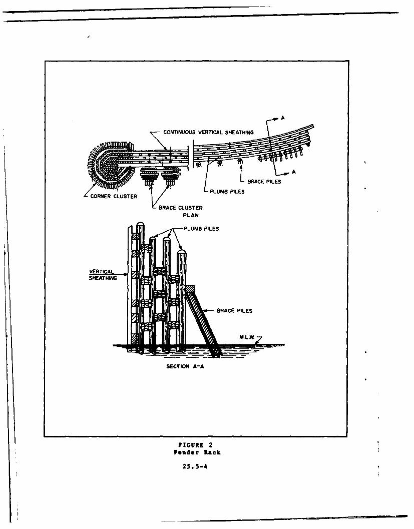
3. FENDER RACKS. These racks usually diverge offshore with inshoreends closely fitting the end contours of ferry boats. Widths ofoffshore openings are determined by the different vessels accommo-dated and site location. The tops of the racks shall be high enoughto enclose the guard rails of the ferries at maximum elevations, thatis, high high water (HHW) plus light draft. Figure 2 shows a typicalfender rack.
a. Design Loadings. Racks shall be designed to deflect anapproaching ferry towards the transfer bridge. For large ferries,approach velocities up to four knots may be considered at incidentangles up to 20 degrees. Points of pile fixity shall be as indicatedin the section on piling of DM-25.6.
b. Construction Details. General construction shall conform torequirements of DM-25.6.
(1) Fender rack piles shall be connected by heavy, longi-tudinal timbers to distribute vessel impacts along an entire rack.
25.5-2

RIFORC tI DoLpt:d ELL TOWER RUNWAY FAES~
PILE DOLPHIN VERTICAL SHEATHING
PLAN SHOWING TYPICAL FACILTIELSHEQHIRENNTERARAGMN
ACK Roo1PIL DOLPHy TLATinRl
CE5TE5-3E
CONTINUOUS VERTICAL SHEATHING
I-BRACE PILES
PLUMB PILESORNER CLUSTER
BRACE CLUSTERPLAN
PLUMB PILES
VERTICALSHEATHING
G-- RACE PILES
SM.L.W4
SECTION A-A
FIGURE 2
Fender Rack
25.5-4
(2) Provide dolphin clusters at offshore ends of racks.
(3) Where more than one row of piles is used in a rack,stagger rear rows from the forward ones and, if necessary, cut offat lower elevations.
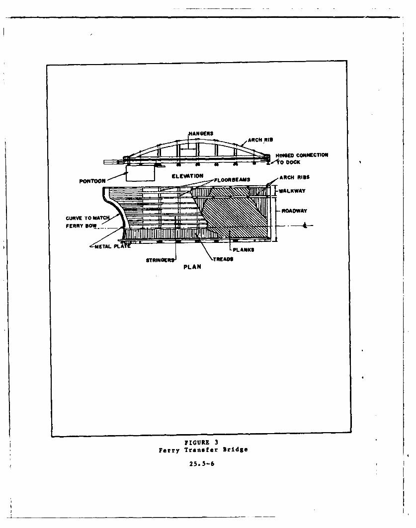
3 4. FERRY TRANSFER BRIDGES. Provide lengths sufficient to hold rampslopes within practical limits at extreme tides and drafts (forexample, 10 percent for trucks and passenger vehicles). The offshorelines should be curved to fit ends of accommodated ferryboats.Figure 3 shows a typical ferry transfer bridge.
a. Operation. Height adjustments of bridge ends are made byhand- or power-operated winches. Lateral adjustments are not madesince ferries are aligned with transfer bridge connections.
~b. Appurtenances. Loads on operating machinery should berelieved by counterweights. The offshore end of a ramp should be
fitted with hardwood, iron brackets, or toggles which may bear on thedeck of a ferry boat. The inshore end of a bridge shall be supportedon rollers, hinged rollers, or sliding bearings, and shall bearlongitudinally against spring or rubber buffers that adequatelyabsorb shocks of incoming boats. Bridges shall be provided withwinches for taking up slacks in mooring lines from ferries totransfer bridges.
Section 3. SMALL CRAFT BERTHING FACILITIES
Part 1. PLANNING AND LAYOUT CRITERIA
1. SITING. The following general principles shall apply for theproper siting of various components of small-craft berthing andberthing facilities:
a. Berthing Craft.
(1) The larger craft shall generally be berthed near theentrance.
a (2) The berthing areas of commercial and recreational craftshall generally be separated because of different land use require-ments. If possible, commercial boats shall be located near the en-trance in a separate basin or across a fairway from the recreational
. craft.
(3) Sailboats without auxiliary power should be berthed inslips that open to leeward of the prevailing winds and that can bereached via wide fairways and channels or routes that permit sailboattacking with least interference to the powered craft.
2
25.5-5
II
HING4ED CONNECTION
POTOONEEVTIN FLOORNEAMS ARCH RID$
CURVE TO MATCFERRY DOW - ................
STRINGER* READ
PLAN
FIGURE 3Ferry Transfer Bridge
25.5-6
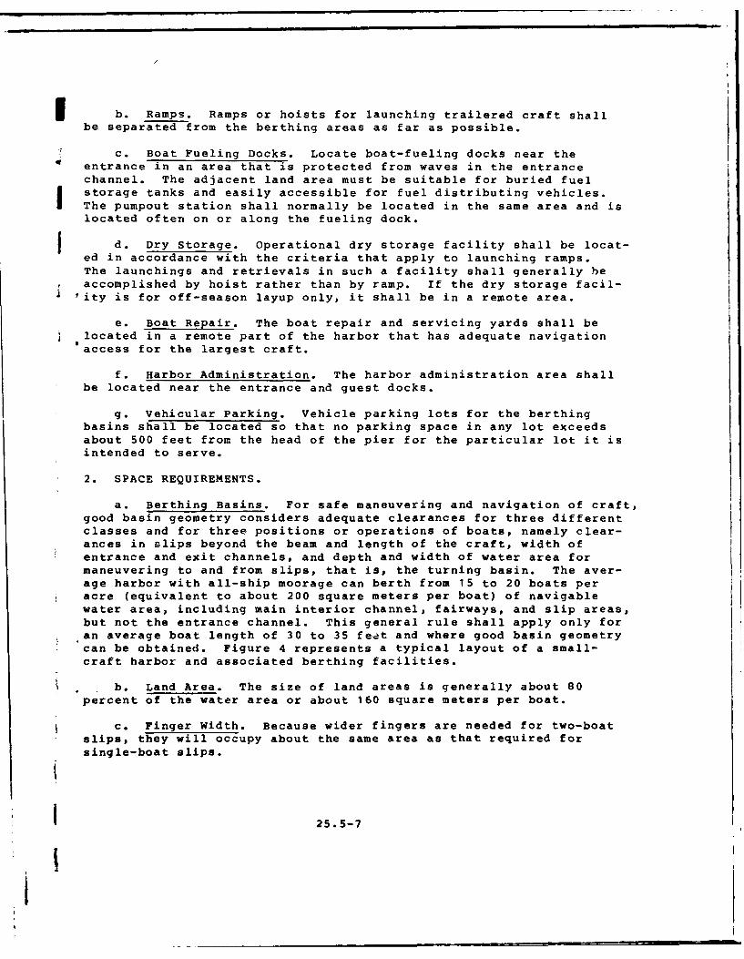
b. Ramps. Ramps or hoists for launching trailered craft shallbe separated from the berthing areas as far as possible.
c. Boat Fueling Docks. Locate boat-fueling docks near theentrance in an area that is protected from waves in the entrancechannel. The adjacent land area must be suitable for buried fuelstorage tanks and easily accessible for fuel distributing vehicles.The pumpout station shall normally be located in the same area and islocated often on or along the fueling dock.
f d. Dry Storage. Operational dry storage facility shall be locat-ed in accordance with the criteria that apply to launching ramps.The launchings and retrievals in such a facility shall generally beaccomplished by hoist rather than by ramp. If the dry storage facil-
'ity is for off-season layup only, it shall be in a remote area.
e. Boat Repair. The boat repair and servicing yards shall belocated in a remote part of the harbor that has adequate navigationaccess for the largest craft.
f. Harbor Administration. The harbor administration area shallbe located near the entrance and guest docks.
g. Vehicular Parking. Vehicle parking lots for the berthingbasins shall be located so that no parking space in any lot exceedsabout 500 feet from the head of the pier for the particular lot it isintended to serve.
2. SPACE REQUIREMENTS.
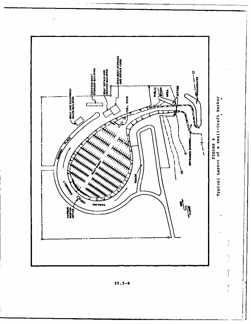
a. Berthing Basins. For safe maneuvering and navigation of craft,good basin geometry considers adequate clearances for three differentclasses and for three positions or operations of boats, namely clear-ances in slips beyond the beam and length of the craft, width ofentrance and exit channels, and depth and width of water area formaneuvering to and from slips, that is, the turning basin. The aver-age harbor with all-ship moorage can berth from 15 to 20 boats peracre (equivalent to about 200 square meters per boat) of navigablewater area, including main interior channel, fairways, and slip areas,but not the entrance channel. This general rule shall apply only foran average boat length of 30 to 35 feet and where good basin geometrycan be obtained. Figure 4 represents a typical layout of a small-craft harbor and associated berthing facilities.
b. Land Area. The size of land areas is generally about 80percent of the water area or about 160 square meters per boat.
c. Finger Width. Because wider fingers are needed for two-boatslips, they will occupy about the same area as that required forsingle-boat slips.
25.5-7
i
ga S
0I 'as -3 wI40
to 00 it f
z Aow
4
0
-4
25.5-8

I d. Water Area. When bow-and-stern moorings are used in lieuof slips, about 2 to 4 times as much water area (depending on thewater depth) is required, exclusive of fairways and channels. Single-
4 point moorings require about 6 times the area occupied by the samenumber of bow-and-stern moorings if full-circle clearance is provided.
e. Launching Ramp or Hoist. An average launching ramp or hoistwill launch and retrieve about 50 trailered boats on a peak-traffic-day.
I f. Parking Lot. For the normal distribution of small boats,a minimum of three vehicle spaces in the-parking lot will be requiredfor every four boats in the berthing area.
g. Harbor Service Facilities. Minimum land area required forharbor service facilities, ancillary facilities, and roads and hard-stands is an area approximately equal to the parking area required
efor berths and operational launchings.
3. BERTHING BASIN DEPTHS. The following criteria shall apply:
a. Factors. The interior basin depth requirements for small-craft berthing shall be determined from DM-26.1 criteria, and also byreckoning the effect of bottom depth on structures of the berthingsystem, such as fixed-pier supports, floating pier guide piles anddolphins, and interior wave and surge baffles.
b. Basis. Assuming that the maximum depression of a boat belowthe stillwater surface will be about 2 feet (due to wave action andscend), the depth shall be at least 2 feet below the keel of thedeepest-draft boat at extreme low water.
c. Minimum Depths. Minimum basin depths shall be as follows:
(1) Main basin channel: 15 feet.
(2) Access slips: 12 feet.
(3) Berths for boats 30 feet and smaller: 8 feet.
(4) Berths for boats 65 feet long: 12 feet.
(5) Berths for boats of intermediate lengths: 8 to 12 feet.
° 4. ENTRANCE CHANNEL tND STRUCTURES.
a. Channel Alignment. The channel alignment shall be as closeto the natural channel alignment as possible.
21 25.5-9
LI

b. Channel Width. The waterside approach to the small-craftharbor shall be as wide as possible to permit safe, simultaneous en-trance and exit of the widest boat anticipated. For small-boat traf-fic, allow a minimum width of 150 feet if the entrance is in linewith the main channel. Allow a minimum of 250 feet if the boat ismaking an immediate turn inside the boat basin.
c. Channel Depth. Entrance channel depth shall be the sum ofdraft, vessel squat, one-half of the wave-height, and overdepth. Anover-depth of one foot to two feet in soft material and 2 to 3 feet inrock is allowed for dredging irregularities. Minimum depths shallrange between 6 feet for boats smaller than 20 feet long and 15 feetfor boats longer than 60 feet.
d. Jetties. Jetties shall be provided to protect the entrancechannel from waves in the basin and from littoral drift entering thechannel from the flanking beaches. Spacing of jetties shall accom-modate both the entrance channel and a protective berm of appropriatewidth on either side of the jetty. Jetties shall be constructed fromthe shore-end outward.
e. Other Protection. Where basin configuration warrants,provide breakwaters, groins, and other basin protection such asbasin flushing and access.
5. TURNING AREA. For average berthing basin conditions, providea width of water area for turning, and entering and leaving slipsequal to 2-1/4 times the length of the longest boat. If there is apredominance of single-screw or twin-screw boats, this criterionshall be 2-1/2 and 2 respectively.
Part 2. ENVIRONMENTAL SITING FACTORS
1. LOCAL WEATHER FACTORS.
a. Precipitation.
(1) Adequate surface drainage shall be provided which iscapable of draining the waters resulting from a maximum probablerainfall without eroding the perimeter land, and diverting anypossible inflows from the surrounding land or safely through thesmall-craft harbor complex.
(2) Covered slips, where necessary, shall be provided tokeep the craft dry above the waterline, and to shed snow, preventhailstone damage, and shield the craft from excessive exposure tosunlight.
(3) In regions where snowfall is heavy, landside structuresand slips shall be designed to carry a heavy snow load or to shedsnow.
25.5-10
b. Wind.
(1) Determine the most severe wind condition that mightoccur at the site from historical meteorological records.
(2) Design floating slips to withstand the horizontal thrustof the berthed craft during the design wind condition.
(3) Suitable anchorage for the slips shall be provided toprevent drifting of the berthed craft and the entire complex underwind stress.
c. Ice.
(1) As precaution against sheet ice damage to boats, specifyboat removal from the water in winter to dry storage or, after hoist-ing out of their slips, leave them suspended above the water surface.
(2) Ice damage to fixed and floating slips occurs in twof ways:
(a) As sheet ice forms, it expands and tends to crushfloats and cut into piles.
(b) If the water level rises after freezing has begun,the ice sheet hugging the piles exerts an upward force tending tojack them up and thereby reduce penetration into the soil. Repeatedfreezing and thawing may eventually lift the piles completely out ofthe soil.
(3) Most ice damage is usually caused by the impact ofdrifting floes on structures as the ice melts in spring.
(4) In areas where freezing does not produce a thick icesheet, ice formation can be prevented near piles, floating slips, andboats by forced convection currents.
(5) Drive steel or metal-clad timber piles deep enough incertain foundation soils to develop higher withdrawal resistance sothat the ice will slide along the pile as it rises.
(6) Floating slips with tapering or round bottoms shall beprovided so that the pinching effect of the ice squeezes them upward.
(7) To prevent erosion of basin perimeters and revettedslopes by expanding ice sheets, the perimeter slopes shall be pro-vided with smooth concrete lining. Vertical perimeter walls may bepushed back into soil behind them in winter and sprung back when theice thaws.
(8) Deflecting booms made of logo or heavy timbers shall beused to protect the berthing area from drifting ice.
25.5-11
|-

d. Fog. For areas where fog is a significant problem, small-craft harbor entrance channels and main fairways should be designedas straight as feasible, so as to be safely navigable in dense fog byfollowing marker buoys and other channel-marking devices with as fewturns as possible.
2. WAVE-RELATED FACTORS.
a. Swell.
(1) To reduce wave action from the entrance channel and in-terior basins to acceptable heights, the entrance channel orientation,protective breakwaters and jetties, and interior wave-dissipatingdevices shall be properly planned and selected.
(2) Historical wave data and statistical hindcast data shallbe used for orienting the entrance and designing protective struc-tures.
(3) Wave-dissipation structures shall be provided to reducewaves to acceptable heights. Criteria for acceptable maximum waveheights are about 2 to 4 feet in the entrance channel, and 1 to1-1/2 feet in the berthing areas depending on the characteristicof the using craft.
(4) Where a small-craft harbor opens into the ocean or alarge lake, the entrance shall be oriented for a boat to enter with-out turning broadside to the incoming waves.
b. Surge.
(1) Surge oscillations in the basin cause stress in mooring
lines and anchorage systems, and can make boat maneuvering into slipsdifficult.
(2) Vertical basin walls are usually more desirable thanpoorly reflective basin perimeters, and rectangular basins are moreefficient than irregular-shaped basins for berthing arrangements.
(3) Most recreational boats in a small-craft harbor are in-sensitive to surge with long periods. However, larger craft mayexperience fender and mooring line difficulties under long-periodsurging.
c. Tides.
(1) Ocean tides may extend considerable length upstream fromthe mouth of large rivers and are semi-predictable for most harborsites. For any coastal site, it is possible to interpolate predic-tions for the site from values given in the Tide Prediction Tables(published annually by the National Oceanic and Atmospheric Adminis-tration) for the two nearest stations.
25.5-12
(2) Extremes of the predicted spring tides provide criteriafor small-craft harbor design accommodating any water level fluctua-tions that may occur.
3. WATER AREA SHOALING FACTORS.
j a. Littoral Drift.
(1) The principal cause of shoaling at entrances to harborsis littoral drift.
(2) The longshore movement of sand is due mainly to waveaction. Structures that change the normal regimen of waves breakingalong a coast may influence the littoral movement.
(3) If the approach of the prevailing waves is normal to theshore, the initial effect is movement of the littoral material fromthe lips inward along each flank of the channel, thereby eroding thelips and shoaling the inner channel. As the process continues, thechannel banks accrete toward the center of the channel, fed bymaterial from the beach on either side of the entrance.
(4) Where the prevailing wave approach is oblique to theshoreline, sediments being transported along the shore by littoralcurrents will be interrupted at the channel opening near the updriftlip and that lip will soon begin to accrete. As the wave-inducedlongshore current again begins to impinge on the shore downdrift ofthe channel mouth, it attempts to reacquire its sediment load. As aresult, the downdrift lip of the channel will erode at about the samerate as the up drift lip accretes, and the channel mouth will migratein the downdrift direction.
(5) To minimize entrance shoaling, install jetties alongeach flank of the entrance channel from the lips of the mouth seawardbeyond the breaker zone. Structural features of jetty constructionshall be such as would prevent the materials from washing through orover the structure into the channel.
b. River Discharge.
(1) Harbors in off-river basins may undergo shoaling due tosediment deposition in the quiet water area and eddy currents thatmay be created by the entrance configuration and the flowing waterin the river.
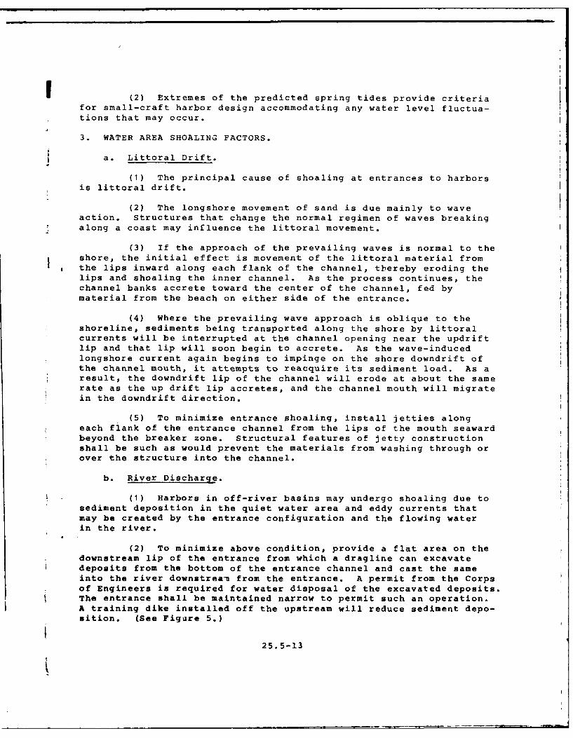
(2) To minimize above condition, provide a flat area on thedownstream lip of the entrance from which a dragline can excavatedeposits from the bottom of the entrance channel and cast the sameinto the river downstreau from the entrance. A permit from the Corpsof Engineers is required for water disposal of the excavated deposits.The entrance shall be maintained narrow to permit such an operation.A training dike installed off the upstream will reduce sediment depo-sition. (See Figure 5.)
25.5-13

River Flow--,. Limit of Bucket CostTraining Dike Probable Shoaling Area
Deposit Area For,Excavated Material
Boat Basin
(1) Permit required from Corps of Engineers for water disposal Ofexcavated material.
FIGURE 5Maintenance of Entrance to Off-River Basin
With Land-Based Equipment (schematic)
25. 5-14

c. Nearby Water Area Structures.
(1) Structures in the water area outside the harborentrance may cause shoaling, especially along shorelines wherelittoral transport is a problem. This type of structure tends toimpound sediments.
(2) Periodic maintenance operations at another harborlocated updrift from the problem harbor may result in depositionof excessive sediment transported downcoast toward it.
(3) On rivers, any structure upstream or across from theharbor may alter the current flow and cause excessive shoaling atthe harbor site.
d. Redistribution of Bottom Materials.
(1) Shifting of bottom materials in some water areas bynatural processes, such as wind waves within the water area, maycause redeposition of these materials in navigation channel andharbor entrances. This will cause the channel characteristics tocontinually change, requiring channel markinc, with buoys, and re-dredging to maintain navigability.
(2) Rivers meander from flood plain and delta aggrada-tion. River flow continuously erodes material from concave bendswhere currents concentrate. The material is then deposited onconvex bars farther downstream where the current is slower.
4. GEOLOGICAL FACTORS
a. Basin Excavation. Where berthing basins require excava-tion as is usually the case, obtain characteristics of the subsur-face below mudline, namely submarine soil types, their degree ofconsolidation or firmness, and the depth of bedrock, to determinethe best method of their removal.
b. Foundations. Obtain geotechnical data, by exploratoryborings, for various subsurface strata to determine the holdingresistance of guide piles, probable lengths of piling for bulkheads,cofferdams, and sizes of other structural foundations and retainingwalls.
c. Material Sources. Obtain data and information on suitableborrow pits for fill and construction materials, nearby aggregateand quarriable stone locations for sized stone for jetties, break-waters, and revetments, and, where channel or basin dredging isrequired, the adequacy of dredged fines and sands for site fillrequirements.
25.5-15
d. Seismic Activity. For earthquake-prone harbor sites,determine the seismic-risk zone designated for the site. Useseismic-design criteria applicable to that zone for design ofberthing facilities and all structural components. (See relevantsections of DM-25.1.)
5. IMPACT ON ENVIRONMENT. Consider the following environmentalissues and concerns, as and where applicable:
a. Disposal of Dredged Material.
b. Water Quality.
c. Perservation of the Ecology.
d. Esthetics.
Part 3. DESIGN CRITERIA FOR THE BERTHING SYSTEM
1. SLIP AND BERTH CLEARANCES.
a. Berth Clearance. For center-to-center spacing of fingerpiers:
(1) In the case of single berths, use the maximum boat widthplus 1-1/2 feet on each side plus the width of finger piers.
(2) In the case of double berths, use twice the averageboat width plus one foot at each finger plus 3 feet between boatsplus the width of finger piers.
(3) Above clearances shall normally apply to 40-foot boats.
b. Finger Piers.
(1) Fingers may be built inclined or perpendicular toheaders. However, the latter orientation is preferred because ofthe simplicity of construction and greater strength of junctionsbetween fingers and headers.
(2) Inclined fingers are generally used only where spacerestrictions limit the turning area opposite the slips or for align-ment in the direction of prevailing winds or water flow.
c. Fairway Widths. For widths of fairways between finger ends,provide:
(1) For power craft, minimum 2 times the length of thelongest craft served.
25.5-16
(2) For sailboats, minimum 2-1/2 times the slip length.
(3) For 4b-degree berthing, minimum 1-1/2 times the lengthI of the longest boat served.
d. Mooring Layouts.
(1) For possible mooring and berthing layouts, and thetype of mooring used in each case, refer to Figure 6. (Also referto DM-26.1.)!
(2) Layout A is not convenient for embarking alongsidepiers. Layout B is not suitable where a large tidal range prevails.Layout D requires wider spacing between finger piers than Layout C.Layout G permits no dry access to land, and poses difficulty inleaving mooring if outer boats are not manned. Layout E providesflexibility in accommodating boats of different lengths, while Lay-out F economizes space and piers.
(3) Layouts G and H are normally not recommended unlessspecial situations and basin conditions warrant.
(4) Access to a star-shaped-cluster moorage is either byshore-boat or by a star-to-shore extension of one of the fingers.
e. Slip and Berthing Arrangements. Features include the fol-lowing:
t(1) In a boat slip, the craft may be tied away from thedock structure, usually with fore-and-aft ties on both ends. In asingle-boat slip, the craft shall be flanked on each side by afinger pier. In a double-boat slip, a tie pile centered betweenthe finger ends or three-point ties or steel whips or any coopera-tive switch-tie system is expedient.
(2) Small boats in relatively quiet waters shall be berthedto a dock with stern hooks or bow clamps.
(3) The most common slip arrangement comprises a seriesof piers or headvalks extending perpendicular to the bulkhead to apierhead line, with finger piers extending at right angles from theheadwalk on either side.
(4) The average headwalk width is about 8 feet with a range* . of about 5 to 16 feet. For wider headwalks, provide some width for
bearing-pile risers, locker boxes, firefighting equipment, andutility lines. For narrower headwalks, locating all obstructionsto knees at the junctions of finger piers is often preferred.Extra-wide headwalks shall generally be used in fixed-pier installa-tions.
25.5-17
i

7 Il~ IrM
A B C D
E F G H
Type of mooring
A Stern to quay, jetty E Alongside quays,or pontoon, bows jetties or pontoonsto piles single banked
F Alongtside quaysjetties or pontoons
3 Ditto but bows up to 3 or 4 abreastmoored to anchorsor buoys
G Between piles
H Star finger berthsC Alonpide finger
piers or catwalksone yacht M eaechside of each ranwe
D Ditto but mm dmon yacht on subwie or each flegi
FIGURE 6
Typical Small-Craft Noorlg Layouts
3. 5-16

f (5) Boarding fingers for single-boat slips shall be about3 feet wide. Floating fingers longer than 35 feet are usually 4feet wide. In double-boat slip construction, use a finger width of4 feet for all slip lengths.
f. Dimensional Criteria and Typical Details.
(1) See Figure 7 for a typical double berthing arrangementthat has been used successfully.
(2) Figure 8 illustrates single- and double-boat slips,angular moorage, applicable fairway widths, and the use of sternhooks and bow clamps.
(3) Figure 9 is a graphical representation of average beamwidth and maximum depth of keels for various craft lengths, and sug-gested widths for right-angle slips where the actual dimensions ofberthing craft are not known.
(4) For typical details, refer to Definitive Designs forNaval Shore Facilities, NAVFAC P-272, Drawing Nos. 1293314 and1293315, titled Small Craft Berthing - Sheets 1 and 2 respectively.
2. FIXED-VERSUS-FLOATING PIER SYSTEM.
a. General Factors. These include the following:
(1) The decision to select fixed or floating piers for anysmall craft harbor basin shall be based on economy, tidal range,safety, and convenience.
(2) For some sites, a combination of fixed and floatingpiers shall generally be considered satisfactory.
(3) Advantages of a fixed-pier system are:
(a) Marginally cheaper to construct.
(b) Less expensive to maintain.
(c) Stronger, more durable and stable.
(d) will bear heavier loadings.
* (e) Withstand impact more readily than floating-piersystem.
25
I 25. 5-19
III

aC
T T''
bu~o
Length of beth. B. Width. W Slip. S. Center to centerfn(ee) (eet0 of piers. (feet)
20 20 35 8330 28 52-56 12140 32 70 IMaSO 36 100 20860 42 120 24870 48 140 28880 $6 160 328
FIGURE 7Typical Berthing Arrangement
25.5-20

I
Sire-Boot Sups rDoube-Goat Saw -TotMoorage
CI
Alternate Narrow SlipsFor Tying -Off Only
Stern BowHooks _ Clamps
I
i FIGURE 8
Small-Craft Berthing Systems
I125. 5-21
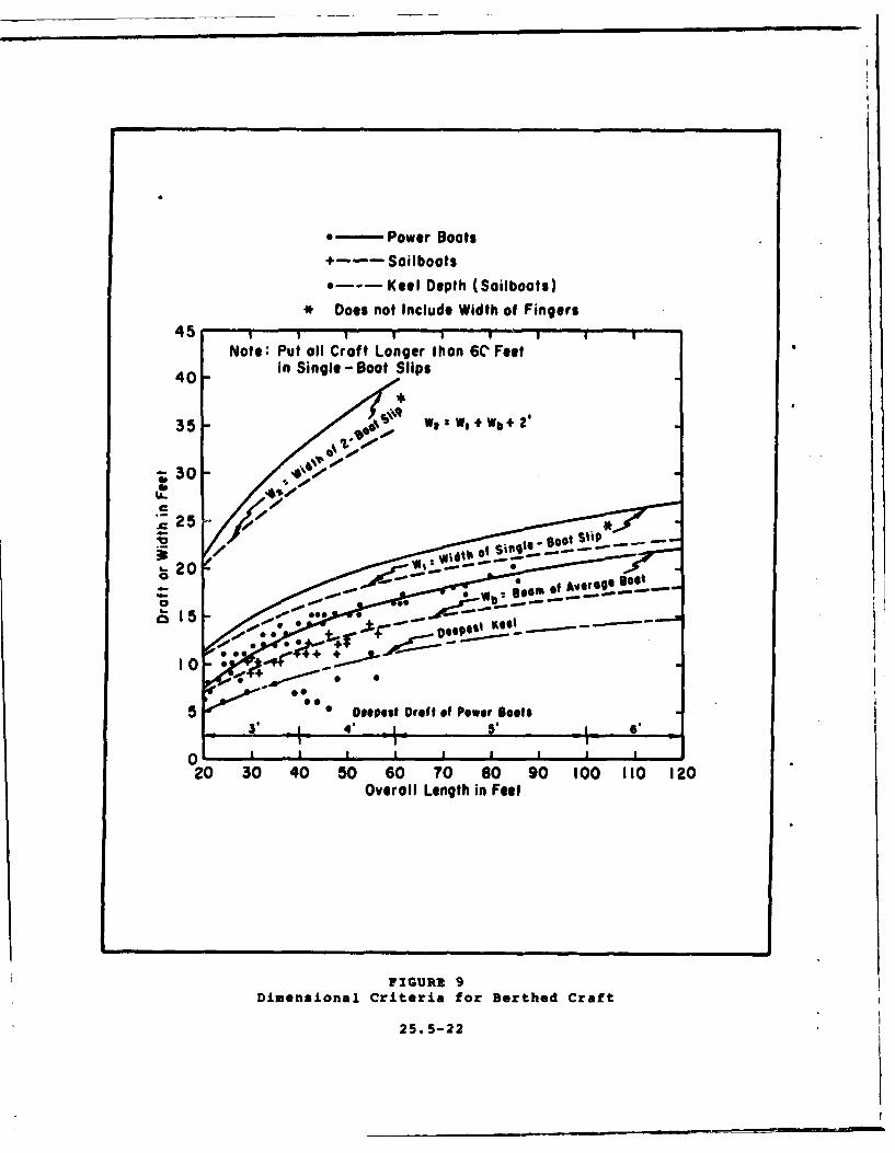
-Power Boats4--Sailboats
*--Keel Depth (Sailboats)* Does not Include Width of Fingers
No;.: Put all Croft Longer than 6C Feet
40 -in Single-Bot Slips
35 - %- w 11+W+2
30
200
o.
5 * Deepest Draft of Power Boots
020 30 40 50 60 70 60 90 100 110 120
Overall Length in Feet
FIGURR 9Dimensional Criteria for Berthed Craft
25. 5-22
(4) Advantages of a floating-pier system are:
(a) Constancy of level between pier and water.
(b) Rearrangement of layout is possible.
(c) Adjustment of mooring lines is unnecessary.
(d) Less likelihood of damage to boats under tidalconditions.
b,, Selection Criteria. These include the following:
(1) In harbor basins, where water surface levels do notfluctuate more than 2 feet and the water depth is about 20 feet orless, the berthing docks and slips should usually be of fixedconstruction.
(2) However, consider use of fixed berths for tidal rangesof up to 5 feet.
(3) Where water surface levels fluctuate more than 5 feet,
a floating-pier system is mandatory.
3. FIXED-PIER BERTHING SYSTEMS.
a. General Features. These include the following:
* (1) Piers shall be no wider than safe pedestrian and hand-cart traffic requires.
(2) Fingers shall be no wider than 3 feet.
(3) Main walkways shall be 4 to 8 feet wide.
(4) Pile trestles are generally used to support stringersand decking with cross and sway bracing installed.
(5) Deck elevations shall be approximately one foot aboveextreme high water.
(6) Construction of fixed-level berthing systems may beeither timber, reinforced concrete, steel, or aluminum. A timbersuperstructure is preferred because of the ease with which attach-ments may be made after final constriction.
(7) Berthing structures and components, using factory-built units for easy field installation, are mostly of tubular andpressed-steel construction with either stamped metal or timberplank decks.
25.5-23
(8) Covered berthing is especially adaptable to a fixed-pier system.
(9) Utility lines shall be carried under the deck or alongthe stringers for supporting the roof.
(10) For deck materials and surface, see applicable criteriaunder Floating-Pier Berthing Systems.
b. Vertical Loading. Design fixed structures for a deck load-ing of not less than 50 pounds per square foot (psf) for fingersand 100 psf for main walks and building floors. When vehicles areto be allowed on main walks, the design loading shall be increasedaccordingly. (See DM-25.1.)
c. Other Design Criteria. Other design criteria shall be asprovided in DM-25.1.
d. Typical Construction. Figure 10 represents a typical fixed-
pier system.
4. FLOATING-PIER BERTHING SYSTEMS
a. General Considerations. These include:
(1) The current state-of-the-art for the selection of themost suitable materials for flotation and for decking the floatingberths is still both controversial and is in the research-and-devel-opment stage. It would, therefore, be best to consider an appro-priate and commonly used and tested system to suit specific basinpeculiarities.
(2) In a floating-pier system, the basic framework thattransmits unequal stresses imposed by current, wave action, andwind from one float to another throughout the system is generallyconstructed of timber. Most other materials cannot take the almostconstant flexure to which the framing is subject over prolongedperiods without fatigup failure. However, some metal stringersystems have been designed with flexible connections which keepflexure below the fatigue failure limit.
b. Flotation Materials.
(1) Timber Log. Although least expensive in some areas,it has a tendency to become water-logged and sink in a few years.Use is generally not recommended.
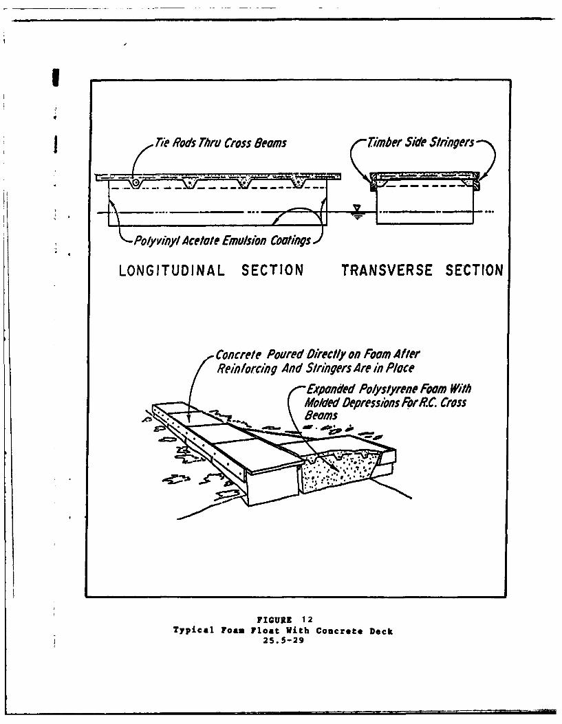
(2) Extruded polystyrene (Styrofoam). Available inseveral sizes of precast or premolded forms, mounted under a timberframe with timber deck.
25.5-24

JBoats 10 360 to 12 200 I 19004-Lockers (typical location) (34'0' to 4O00(l'.0
aorngcs above 4 1900__ Piles
wlwyFinger Pier Boats 8 530 to 10 360 4.250P l a n a t o a t s 2 '0 to 8 3 0 ( W* )
Walkway as abv 4.250
* bulkhead
*walkWay 3800730 o8 3Pla at (12'6')SBulk head wall(2'to80"(width hlf 3800-
-- of walkway)asboe30
2750 4.900 tI-701
j10530 (34'-o- _
13/.00 (440o"Light standard270 90'
Sevces duct
Removable lockersExtended vertical bumpers
at Sl rt16,"IcewasOpen jointed deck
Moorig harwareContinuous joistshigh and lowwater leel PA%01
F o* l Finger pw
* Creosoted pine pilesVertical bumpers Cniuu tiwat 610mm 12,(0)cente Cotnustigr
Low water level Cross bracing
-- DIMENSIONS ARE IN MILLIMETERS.EQUIVALENT DIMENSIONS IN FEETARE IN PARENTHESES.
FIGURE 10Typical Fixed Finger Pier System
25. 5-25

(3) Expanded-pellet polystyrene. Material shall be firmin composition and essentially unicellular. Polystyrene pianksshould conform to the following requirements:
(a) Be hydrocarbon-resistant, and evidence no apparentsoftening or swelling, when tested by the immersion method stipulatedin the Military Specification MIL-P-40619.
(b) Meet minimum 1-1/2 pounds per cubic foot (pcf)density; 20 pounds per cubic inch, at 5 percent deflection, compres-sive strength; 40 pounds per square inch (psi) tensile strength; and25 psi shear strength.
(c) Have maximum water absorption of 0.12 psf of skin-less or rindless surface, when tested by the immersion method stip-ulated in Military Specification MIL-P-40619.
(4) Polyurethane Foam. This is more expensive than poly-styrene foam. However, because of its hydrocarbon resistance, itis sometimes preferred. It requires covering with an oxidation-resistant material, and the nonabsorbent, noncellular varietyshould be specified.
(5) Waterproof Shells. Shell-type floats can be ballastedwith water or sand to allow corrective leveling of the deck afterinstallation. However, they are susceptible to leakage and loss ofbuoyancy if the shell becomes permeable for any reason. Some ofthe shell-type floats in use are:
(a) Fiberglass or plastic-coated shell with a moldedfoam core ovi.r which a reinforced concrete deck is poured. Theedge beam, cross beam, and the tie-rod system in this constructionmake the units exceptionally tough and strong. Synthetic shellfloats are not affected by hydrocarbons, brackish water, or anyother common contaminant likely to be found in a small craft harbor.
(b) Prefabricated metal floats of steel and aluminum.The shells are folded and welded into rectangular units comprisingthin-gauge sheets with stiffening baffles for greater strengths.Preservative coatings are applied to both sides of all corrodiblemetals. Their use in freshwater harbor basins is feasible, butin saltwater environment, the use of metal floats still remainsquestionable.
(c) Jettisoned fuel tanks from military aircraft.This type is expedient when sufficient surplus can be procured atlow cost.
(d) Pipes. Tubular steel floats with attached clipangles at each end bolted to a steel deck framework are used.Coating the entire framework, including the tubes, with coal-tarepoxy provides protection against corrosion.
25.5-26
(e) Steel drums. They are expedient and inexpensivein short-life or substandard construction. Maintenance costs inseawater would be prohibitive.
(6) Concrete Floats. These provide maintenance-free per-manence to concrete construction and added stability to the float-ing pier. Lightweight aggregates to keep the dead load to a minimum,prevention of shrinkage cracks, honeycombing and segregation, andprecise mix control are essential. Concrete floats can be made withor without reinforcement. When concrete floats are reinforced, agalvanized wire mesh shall normally be used. The float should bedesigned so that at no point will the allowable tensile strength ofthe concrete be exceeded.
(7) Wooden Floats. Consider the following:
(a) Pressure-treated wood is in use for floating dockmodules. All wood shall be treated in accordance with AWPB StandardMLP-76 for marine (saltwater) exposure.
(b) Flotation units shall include polyethylene pan,polystyrene foam block, and polyethylene cap sheet.
(8) Figures 11, 12, and 13 show various types of floats in
common use.
c. Deck Materials and Surface.
(1) Woodplank Deck. It is used without a coating and alsowith coating to minimize splintering. Roughened surface texture ofcoatings imparts nonskid quality. Planks should not exceed 10 inchesin width and shall be spaced 1/4 inch apart. Diagonal planking issometimes used for floating docks to provide cross-bracing strength.For good appearance and wearing quality, the planking should be giventwo priming coats.
(2) Plywood Decking. Commercial grades of exterior ply-wood are made with waterproof glues of excellent quality and may besafely used for exposed decking. Plywood of 3/4-inch thickness ismore expensive than 2-inch wood planking, but provides greaterstructural strength in cross bracing. Plywood decking should becrowned slightly to avoid ponding in wet weather. It should bepainted as described for wood planks. A synthetic surfacing may bepressure-bonded to plywood deck panels under heat to provide non-skid and long-wearing quality.
(3) Laminated Plank Deck. It uses nominal 2-by 3-inch or2-by 4-inch cedar sticks glued together side by side for use incontinuous decking in large, thick planks of any length or widthand provider. high stiffness. Laminated decks may be used withoutany additionil framing.
25.5-27

Plastic Dumper 2 X 8 Diagonal Decking Fbrls nae lwoAStm*) -T2p WXo 10hdCotn W/Lipe For selling To Stringers
3/4" Maple -Pla, (Typ. All Systems)See
Gluloan 4oml Stringer
2 X BlokingCleats Where2t CF$ WBONg_ 2 X 9 Diaglonal Docking Needed (Typ, AN SFtLogonlhi
At ros Wge-- W/NW.-Sa otn Systems) Bolt concrete Floats --
X 4 Thru Stringer f -Stool Studs-4 N______________________Wlded To
A -Epxy Sol AInsp kig 2 X 0 skeirs 12' C.C.
r.ecast Seolc Tb Stringer lU'-Polysterens(No Reinforcement)
Glued Sandwich NO,,\ 3/4" PlywoodLghwgtCoreeDsWI~o -Shd CotingPawred After Assembly
'Polystyrene Core--,
3/B" Ply,~npPu
Polystyrene Floal, Reinforced Deck -Form InsertPolyethylene N. -Fiberglass __
Wes Dallas# Sheath Shell
Drain Wes
Leg To Stringer -Prosaura goaded Silicon -CotuuslusDc12" CC.- ,,Plastic W/Grid Surface (/on.S otinuos glsDc
'3/4' Crown, I6 4X W/NlueSkag BoltiIStringer /--" 2 N o 10 S trne
L34 E -lns. Plug r/ 0Srne
3/"Ct. Plywood ILips Glued TO Deck
'-..friberglass,- 2 X 10 Fiberglass shall
Shall I Stringer WPyslyne cars
FIGURE 11Various Types of Floats
25. 5-28
II
-:Polyvinyl Acetate Emulsion Coatigs
LONGITUDINAL SECTION TRANSVERSE SECTION
Concrete Poured Directly on Foam AfterReinforcing And Stringers Are in P/ace
Expanded Polystyrene Fawm WithMolded DepressIons For P.C. Cross
FIGURE 12Typical Foam Float With Concrete Deck
25. 5-29
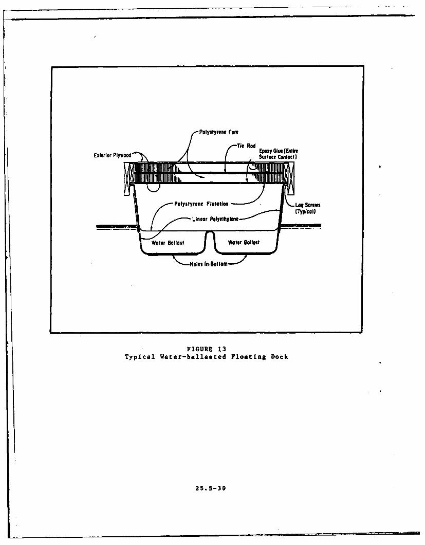
Polystyrene Core
Exterior Plywoodac onat
Water Ballast Water Ballast
Holes In-Bottom
FIGURE 13Typical Water-ballasted Floating Dock
25.5-30
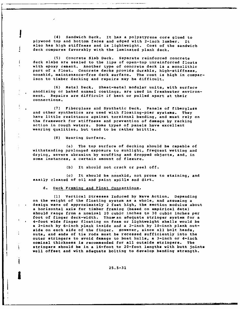
(4) Sandwich Deck. It has a polystyrene core glued toplywood top and bottom faces and edged with 2-inch lumber. Italso has high stiffness and is lightweight. Cost of the sandwichdeck compares favorably with the laminated plank deck.
(5) Concrete Slab Deck. Separate reinforced concretedeck slabs are sealed to the lips of open-top unreinforced floatswith epoxy cement. Another type of concrete deck is a monolithicpart of a float. Concrete decks provide durable, high-stiffness,nonskid, maintenance-free deck surface. The cost is high in compar-ison to timber decking and repairs may be difficult.
(6) Metal Deck. Sheet-metal modular units, with surfaceanodizing or baked enamel coatings, are used in freshwater environ-ment. Repairs are difficult if bent or pulled apart at theirconnections.
(7) Fiberglass and Synthetic Deck. Panels of fiberglassand other synthetics are used with floating-pier systems. Theyhave little resistance against torsional bending, and must rely onthe framework for stiffness and prevention of damage by rackingaction in rough waters. Some types of panels have excellentwearing qualities, but tend to be rather brittle.
(8) Wearing Surface.
(a) The top surface of decking should be capable ofwithstanding prolonged exposure to sunlight, frequent wetting anddrying, severe abrasion by scuffing and dropped objects, and, insome instances, a certain amount of flexure.
(b) It should not crack or peel off.
(c) It should be nonskid, not prone to staining, andeasily cleaned of oil and paint spills and dirt.
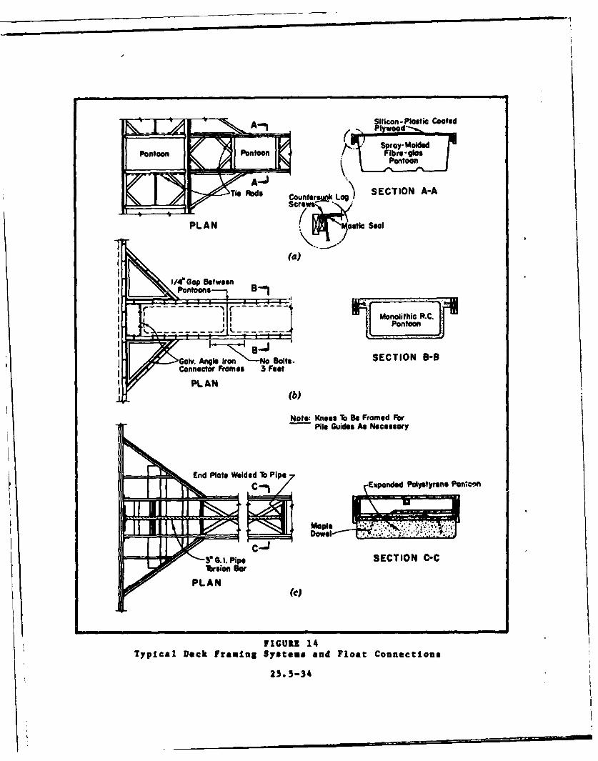
d. Deck Framing and Float Connections.
(1) Vertical Stresses Induced by Wave Action. Dependingon the weight of the floating system as a whole, and assuming adesign wave of approximately 2 feet high, the section modulus abouta horizontal axis for timber framing (based on empirical data)should range from a nominal 20 cubic inches to 30 cubic inches perfoot of finger deck-width. Thus an adequate stringer system for a4-foot wide finger floating on foam or lightweight shells would bea 2-inch by 6-inch plank inside and a 2-inch by 10-inch plank out-side on each side of the finger. However, since all bolt heads,nuts, and ends of tie rods must be recessed sufficiently into theouter stringers to avoid damage to boat hulls, a 3-inch or 4-inchnominal thickness is recommended for all outside stringers. Thestringers should be in a 16-foot to 20-foot lengths with butt jointswell offset and with adequate bolting to develop bending strength.
25.5-31
I
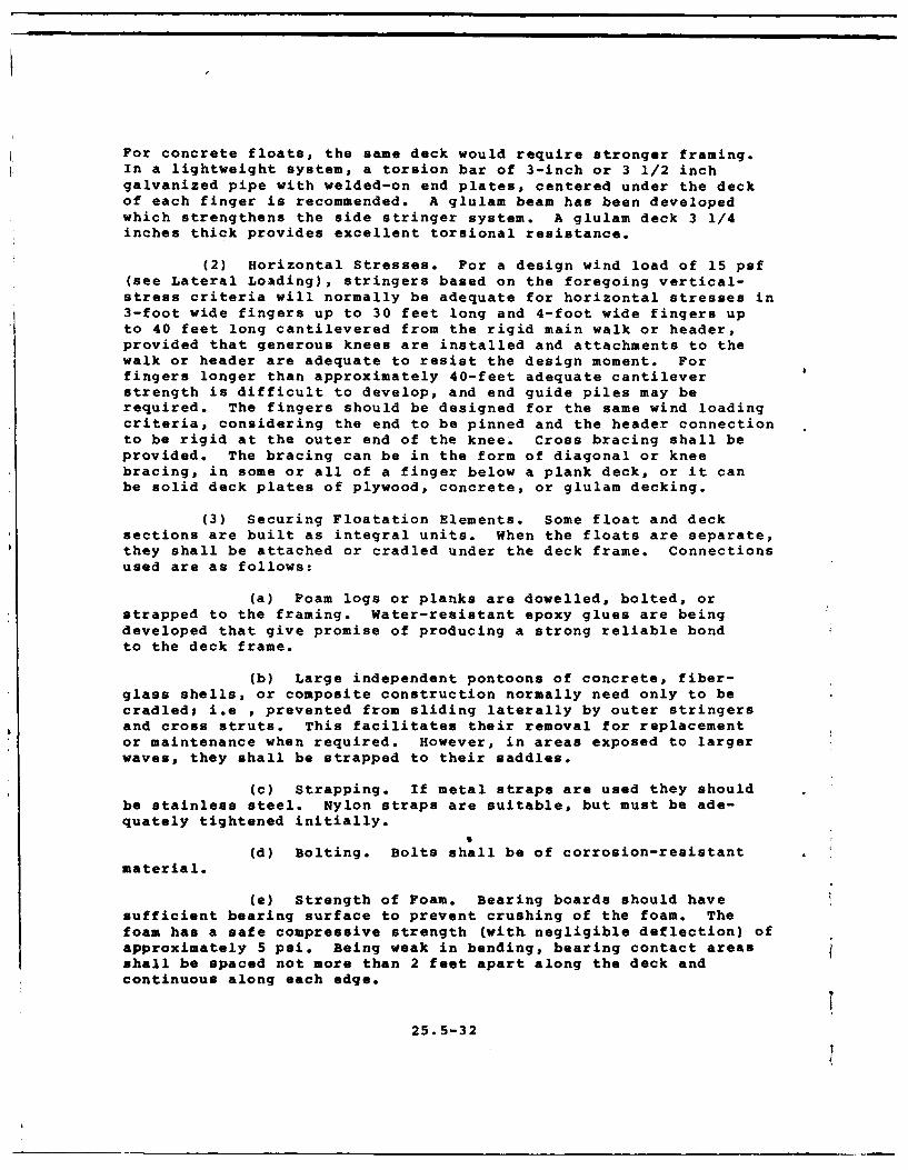
For concrete floats, the same deck would require stronger framing.In a lightweight system, a torsion bar of 3-inch or 3 1/2 inchgalvanized pipe with welded-on end plates, centered under the deckof each finger is recommended. A glulam beam has been developedwhich strengthens the side stringer system. A glulam deck 3 1/4inches thick provides excellent torsional resistance.
(2) Horizontal Stresses. For a design wind load of 15 psf(see Lateral Loading), stringers based on the foregoing vertical-stress criteria will normally be adequate for horizontal stresses in3-foot wide fingers up to 30 feet long and 4-foot wide fingers upto 40 feet long cantilevered from the rigid main walk or header,provided that generous knees are installed and attachments to thewalk or header are adequate to resist the design moment. Forfingers longer than approximately 40-feet adequate cantileverstrength is difficult to develop, and end guide piles may berequired. The fingers should be designed for the same wind loadingcriteria, considering the end to be pinned and the header connectionto be rigid at the outer end of the knee. Cross bracing shall beprovided. The bracing can be in the form of diagonal or kneebracing, in some or all of a finger below a plank deck, or it canbe solid deck plates of plywood, concrete, or glulam decking.
(3) Securing Floatation Elements. Some float and decksections are built as integral units. When the floats are separate,they shall be attached or cradled under the deck frame. Connectionsused are as follows:
(a) Foam logs or planks are dowelled, bolted, orstrapped to the framing. Water-resistant epoxy glues are beingdeveloped that give promise of producing a strong reliable bondto the deck frame.
(b) Large independent pontoons of concrete, fiber-glass shells, or composite construction normally need only to becradled; i.e , prevented from sliding laterally by outer stringersand cross struts. This facilitates their removal for replacementor maintenance when required. However, in areas exposed to largerwaves, they shall be strapped to their saddles.
(c) Strapping. If metal straps are used they shouldbe stainless steel. Nylon straps are suitable, but must be ade-quately tightened initially.
(d) Bolting. Bolts shall be of corrosion-resistantmaterial.
(e) Strength of Foam. Bearing boards should havesufficient bearing surface to prevent crushing of the foam. Thefoam has a safe compressive strength (with negligible deflection) ofapproximately 5 psi. Being weak in bending, bearing contact areasshall be spaced not more than 2 feet apart along the deck andcontinuous along each edge.
25.5-32
1 (4) Figure 14 represents typical deck framing and float
connections in use.
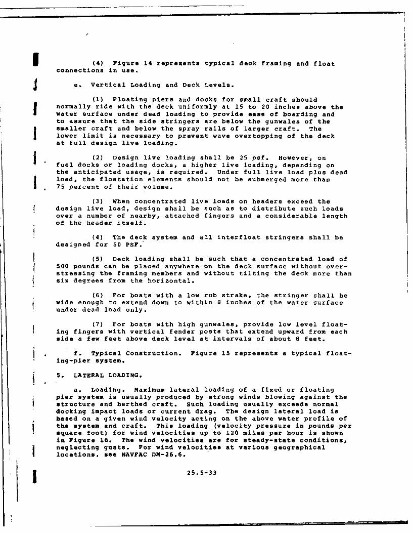
4e. Vertical Loading and Deck Levels.
(1) Floating piers and docks for small craft shouldI normally ride with the deck uniformly at 15 to 20 inches above the
water surface under dead loading to provide ease of boarding andto assure that the side stringers are below the gunwales of thesmaller craft and below the spray rails of larger craft. Thelower limit is necessary to prevent wave overtopping of the deckat full design live loading.
f(2) Design live loading shall be 25 psf. However, onfuel docks or loading docks, a higher live loading, depending onthe anticipated usage, is required. Under full live load plus dead
jload, the floatation elements should not be submerged more thana 75 percent of their volume.
(3) When concentrated live loads on headers exceed thedesign live load, design shall be such as to distribute such loadsover a number of nearby, attached fingers and a considerable lengthof the header itself.
(4) The deck system and all interfloat stringers shall bedesigned for 50 PSF.
(5) Deck loading shall be such that a concentrated load of500 pounds can be placed anywhere on the deck surface without over-stressing the framing members and without tilting the deck more thansix degrees from the horizontal.
(6) For boats with a low rub strake, the stringer shall bewide enough to extend down to within 8 inches of the water surfaceunder dead load only.
(7) For boats with high gunwales, provide low level float-ing fingers with vertical fender posts that extend upward from eachside a few feet above deck level at intervals of about 8 feet.
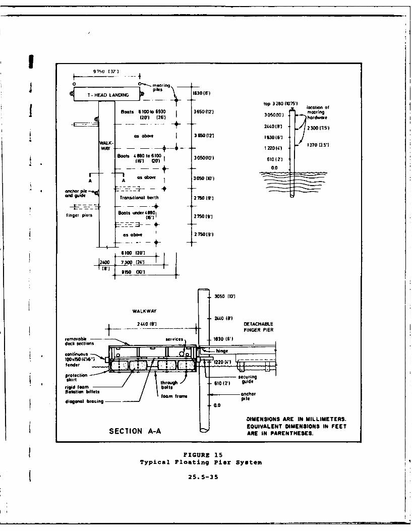
* . f. Typical Construction. Figure 15 represents a typical float-ing-pier system.
5. LATERAL LOADING.
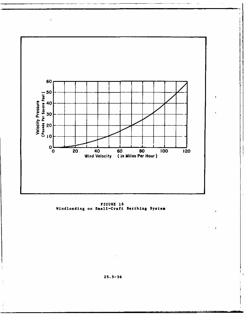
a* Loading. Maximum lateral loading of a fixed or floatingpier system is usually produced by strong winds blowing against thestructure and berthed craft. Such loading usually exceeds normaldocking impact loads or current drag. The design lateral load isbased on a given wind velocity acting on the above water profile ofthe system and craft. This loading (velocity pressure in pounds persquare foot) for wind velocities up to 120 miles per hour is shownin Figure 16. The wind velocities are for steady-state conditions,neglecting gusts. For wind velocities at various geographicallocations, see NAVFAC DM-26.6.
1 25.5-33
-. licon-latiOc Coated
PontooPoPonoon
Tie Fbds Co Lag') SECTION A-A
PLAN (ste Sea
I IN. /4' Gp Between
Monolithic R.C.
Gov ni ro -oBolts- SECTION 8-8Connector Frames 5 Feet
PL AN(b)
Note: Knees lb Be Framed FarPile Guides As Necessary
End Plate Wle oPp
C-1d Pi7 Expanded Poytyrene ponfl.-n
Doe
ar 0 1. ipeSECTION C-C
PLAN(C)
FIGURE 14
Typical Dock Framing Systems and Float Connections
25.o5-34
0 O'-mooring 306
~ piles---- ' to HEADL AD4 160(gt top 2W I location of
Boats 6 1O0to 630 3 6500(21 305000') Z mooring120)1(261 hardware
+ ~~~2440 (8'613017F
as above I 36500121 1930 (61WALK- --- 2(' 1370 (3.51
Boats 4880to6100300160 2(161 W)~ 00(0 1 2
-- 0.0
an Aud A- asbove 350 (10')
a nchor ile -,.-*0-andgudeTransitional berth 2 750 (9)
finger piers Boats under 248801
as above 2 750 (9*)
6100o (201
12400 7300 1240(6') 9150 (301
3050 (101
WALK WAY2440 (81
2440 (81 DETACHABLE
- FINGER PIER
rmvbeservices 1630 (6')
continuous ihng*100O50 - 1220 W
ptection sc :I.X shrt truh610 (21 guide
lotation billets wac r
diagonat bracingfomrae00 pl
DIMENSIONS ARE IN MILLIMETERS.
SEC71N A-AEQUIVALENT DIMENSIONS IN FEETSECTIN A-AARE IN PARENTHESES.
FIGURE 15Typical Floating Pier System
25.5-35
o40---0r
0
> *
*01
o 0 20 40 60_ so 00 12
WidVloiy i MlsPe or
WindlodnWind VmalCity t Biiestin PersHour
25. 5-36
3 b. Analysis.
(1) Check both parallel and perpendicular directions tothe main walk.
(1) Determine average profile height for berthing craft.(See Figure 17.) It is often taken as 15 percent of the slip lengthin open berths.
(3) In computing the parallel windload on a line of boats,assume that all shielded craft experience only 20 percent of thewindloading that is applied to the first (unshielded) boat.
o(4) In computing the perpendicular windloading on a system,
obtain the total area on which the wind acts by multiplying theaverage craft profile height by the slip width and that product bythe total number of slips, then adding to the result the abovewater areas of the finger pier ends exposed to the wind.
(5) Where slips are provided on both sides of the mainwalk, the area calculation shall include the side that berths theset of boats with the largest average profile height.
(6) Multiply above value by 115 percent to account for thewind force on the sheltered or leeward boat row.
(7) Figure 18 represents a sample computation for lateralloading on a typical open pier system.
6. ANCHORAGE SYSTEMS.
a. Selection Criteria. Floating piers and docks should be an-chored against lateral movement likely to be caused by wind, watercurrents, and vessel, ice or floating-debris imnact. For selectionof an anchorage system, consider depth of water in the small-craftbasin, extent of water-level fluctuations, the prevailing current,and the submarine bed material.
b. Systems.
(1) Anchor Piles. These are simple and are the mostcommonly used. They require firm but penetrable subsurface strata,a bottom depth not exceeding 30 feet at highest water level, andrelatively moderate horizontal loading conditions. Where pileanchorage is used, guides shall be incorporated in the deck struc-ture. Commonly used guides are metal hoops, rectangular wood collars,and rollers. In well-protected basins, use rollers only for thosepiles that are found to be in almost continuous contact with theguides. Use collars with hardwood blocks at other piles. Metalhoops shall not be used with bare wood piles since they tend to crushthe wood fibers.
25.5-37
I i ii i
i~
FIGURE 17
Variation of Average Profile Height ofBerthed Craft with Craft Length
25.3-30

I-
/, Poro//el Wind 20
*
NOT TO SCALE
o Design Wind Load: 15 PSF
o Perpendicular Wind40' Boats: 8 Each x 19' Beam x 5.5' Height x 15 PSF = 12,540 Lbs.Fingers: 9 Each x 4' Width x 1.5' Height x 15 PSF 810
13,350 Lbs.
Multiply by 1.15 for Row of 30' Boats - 1.15 x 13,350 Lbs. 15,352.5 Lbs.78' Boat: 20' Beam x 7.4' Height x 15 PSF 2,220.0 Lbs.
TOTAL PERPENDICULAR LOAD: 17,572.5 Lbs.
o Parallel Wind
78' Boat: 78' Each x 7.4' Beam x 15 PSF = 8,658 Lbs.40' Boats: 8 Each x 40' x 5.5' Height x 3 PSF = 5,280 Lbs.30' Boats: 10 Each x 30' x 4.8' Height x 3 PSF - 4,320 Lbs.
TOTAL PARALLEL LOAD: 18,258 Lbs.
o Reckon Parallel Windloading for Design
FIGURE 18Sample Calculation for Windloading
on a Floating Pier System
25.5-39

(2) Anchor Lines. Where a boat basin is constructed indeep water or where large water-level fluctuations occur, floatingstructures are usually anchored in place with steel cables or chains.Where the entire floating system requires movement through consider-able distances in and out with water-level changes, special anchorbarges with hand winches are used. A line-anchorage system usuallyuses two outer anchor lines extending about 45 degrees from theouter corners of the floating system, and two lines tying the systemb-ck to shore.
(3) River Anchorage. River currents usually stress an an-chorage system more severely than still-water or tidal basins.Long, trailing finger piers are usually used, tied to trees on thebank upstream, to piles or to dolphins. Figure 19 represents atypical river anchorage system.
(4) Anchorage of Covered Floating System.
(a) Dolphins are usually used instead of anchor piles.
(b) If the water depth is significant, submergedstructural ties across finger ends well below the keel depth of theberthed craft are sometimes used to strengthen a covered floatingsystem. (See Figure 20.)
7. APPROACH PIERS AND GANGWAYS.
a. General Criteria. These include the following:
(1) Access to the berthing docks and slips from the basinshall be accomplished by a fixed-pier approach (brow) to a fixedberthing system and by a hinged gangway to a floating-pier system.
(2) Fixed-pier approach is an extension of the headwalk toa landing on the bulkhead wall or an abutment at the shoulder of asloping bank. In floating systems, one end of the gangway shall besupported on floats. It should, therefore, be lightweight and onlylong enough to result in some predetermined maximum slope (1 on 3)at extreme low water level. For slopes steeper than I on 3, ahinged staircase with self-leveling steps shall be provided.
(3) Where the boat basin perimeter is appreciably higherthan maximum high water, the brow shall be ramped down to one footor two feet above the elevation at its outer end to decrease theslope of the gangway at low water.
(4) The gangway may be narrower than either the approachpier (brow) or the main walk.
25.5-40
i
If Flow Pile
Dolphin
Allow 1.5 Boat Width--
I.I
Gangway Acts As Hinged Strut
- - jim~ Bank
Large Tre\
Or Pile
FIGURE 19
Typical River Anchorage System
j25.5-41

Oil
.,.
FIGURE 20Typical Use of Submerged Croesties
to Strengthen Covered Floating System
25. 5-42
(5) Length of gangways *.all be such that the slope willnot be greater than approximately 1 on 2-1/2 at maximum low water.
(6) Weight of gangways shall be kept as small aspossible.
(7) Gangway construction may be of timber, steel, aluminum,fiberglass, or a combinati n of these materials. A typical gangwayis a pair of steel or wood stringers with a plywood deck.
(8) Gangways shall have handrails. A L-foot width betweenhandrails is the minimum, and 4 to 5 feet is the minimum if thepier has multiple berths or if the gangway traffic is heavy.Typical construction is Warren-truss welded-pipe handrail.
(9) Gangways shall be hinged at the top inside edge of aperimeter bulkhead wall. If the perimeter is a sloping bank,provide a short fixed-approach pier to reduce the length and weightof the gangway. The hinge at the upper end of the gangway shall beof rugged design.
(10) Provide sliding ends for gangways weighing less than500 pounds. For heavier gangways, provide rollers and aprons. Theapron plates shall be long enough to clear the ends of the rollerguides at low water level and attached to the bottom end of thegangway with a pipe-and-rod hinge. (See Figure 21.)
Part 4. DESIGN CRITERIA FOR OTHER SHELTERED BASIN STRUCTURES
1. PERIMETER STABILIZATION.
a. Obiectives. Perimeter stabilization shall be provided:
(1) To retain the perimeter material or to hold it on agiven slope against such internal forces as those causing sloughingor piping of material under a wall or through a revetment.
(2) To prevent damage to the perimeter by such externalforces as might erode or damage the slope or perimeter wall throughwave action, currents, and impact by floating objects.
b. Structures. The perimeter inside the sheltered harbor basinshall, depending on the bank conditions and the degree of stabili-zation required, be designed as:
(1) Perimeter beach of existing or imported materials.
(2) Revetted slope.
(3) Gabioned slope.
225. 5-43It

-- / Wheel GuideGangway 1/4"Apron Plate
- __/ Deck Plate
Wear Lip ScrewedCurb Each Side To Keep to PlateUnderside Gangway Clear
7/8" Steel Rod
IStandard PipeWelded to Apron
il
FIGURE 21Framing and Hinge Detail for Pipe-and-Rod Plate
Hinge for Heavy Gangway
25.5-44
(4) Vertical bulkhead.
(5) Some combination of the above.
2. PERIMETER BEACH.
a. Slopes.
(1) Where economic considerations warrant that the perim-eter of the basin be a sand beach, the slope shall not, ordinarily,be steeper than 1 on 8 (and, 1 on 10 for fine sand) within themaximum range of water-level fluctuation in the basin.
I ((2) Where the shore face consists of gravel, pebbles, orsimilar rock fragments or sizes rather than sand, littoral transportprocesses are usually too weak to cause any significant lateral dis-placement and the slope may be increased up to about 1 on 5.
(3) Underwater stable slopes at depths of 3 feet or morebelow extreme low water vary from about 1 on 4 for cohesion-less fine silty sands to about 1 on 1-1/4 for some clayey soils incuts.
(4) Bay mud and some lake-bottom materials often "fluffup" upon dredging, and will stabilize only on underwater slopes of1 on 10 or flatter. Waste such material outside the basin and sta-bilize the slopes with imported sand.
b. Profile. Figure 22(a) represents a typical beach slopeprofile.
c. Design Details. (See Shore Protection Manual, Volumes I andII.)
3. REVETTED SLOPE.
A. Revetments.
(1) Where bank conditions require armoring the slopes, pro-vide a revetment of armor stone layer or precast concrete slabsplaced on a filter course of spalls or gravel or tough, continuoussynthetic cloth.
(2) Revetments are normally stable only to a steepness ofabout 1 on 1-3/4.
(3) Materials used are armored stone or precast concreteblocks.
b. Armoring.
(1) Extreme wave action and currents will determine minimumstone size of a riprap or revetted slope.
25.5-45

(2) Because of the rong pumping action of waves and eddycurrents, armor stones shall have a normal thickness of twice theaverage stone dimensions.
c. Filtering Devices. These are:
(1) Poorly-graded gravel or stone filter.
(2) Continuous, tough synthetic cloth filter.
d. Profile. Figures 22(b), 22(c) and 22(d) represent typicalrevetted slope profiles.
e. Design Details. (See Shore Protection Manual, Volumes Iand II.)
4. GABIONED SLOPE.
a. Use. Where adequate small-size stone is available, rock-filled wire-mesh gabions permit installation of steep slopes forperimeter stabilization at relatively low cost.
b. Construction.
(1) Heavy-duty wire mesh baskets with rectangular sidesand of convenient size tailored for construction are commerciallyavailable for shipment to site in collapsed form.
(2) They are galvanized for freshwater use, and galvanizedplus PVC-coated for saltwater use.
(3) The filled baskets may be placed vertically on top ofeach other.
(4) For greater stability, they should be canted back toabout a 4 to 1 batter. Battering may also be done by setback ofsuccessive rows for a terraced appearance.
(5) The gabioned slope shall be backed by a layer of filtercloth to prevent the pumpout of fine material from the earthbank be-hind it.
(6) Use of gabion construction has been limited so far.Its permanence is not yet well established.
c. Typical Details. (See Figure 23.)
25.5-46
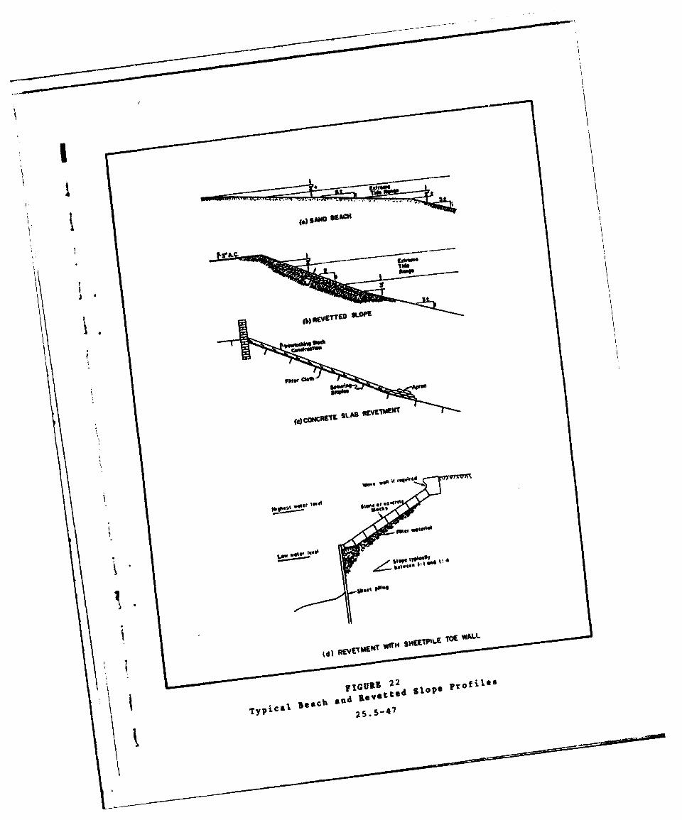
... ......
(4)compnC~ SLAS IVTM
VW V* W "" e
nd ivetto 1o
'typical Bech an 25.5-~47

rrANow Pier
Wooden Float
high Water Line
New Filled Land Area
LoFilter
Clot
SECTION A-A SECTION B-B
4" 1 4" Timber Fender oin
SECTION C-C SECTION 0-0
FIGURE 23Typical Use of Gabions in Small-Craft Harbor construction
25. 5-48

5. VERTICAL BULKHEAD.
a. Use Criteria. For small-craft berthing basins, consider thefollowing:
(LO Vertical walls reflect waves and should be avoided wheresurge and partially attenuated wave penetration into the basininterior cannot be satisfactorily avoided.
(2) If the site can be readily unwatered and if substrataare not so fluidic as to require deep cdt-off walls, cast-in-placeconcrete bulkhead construction shall be used.
(3) In other cases, use sheetpiling bulkhead.
(4) Because the perimeter wall in a small-craft harbor isseldom used as a breasting dock, the bulkhead is usually carriedonly to the low water elevation, and a partially revetted underwaterslope shall extend from the base of the bulkhead wall down to designdepth.
(5) The lower edge of the bulkhead wall shall extend notless than 2 feet below the lowest low water. Where wave or otherwater action occurs, extend the walls below the lowest low waterto a minimum depth of two times the maximum wave height tominimize the possibility of pumpout of fine material from behindthe wall.
(6) The top of the bulkhead wall shall be 2 or 3 feetabove maximum high water.
b. Types. Types used for sirall-craft basins include:
(1) Tie-back pile-type timber bulkhead.
(2) Steel or aluminum sheetpile bulkhead.
(3) Concrete bulkhead.
(4) Concrete structure with revetted slope.
co Design Details. For design details, refer to DM-25.4.
d. General Considerations.
(1) Timber bulkheads often fail because of corrosion, ab-rasion, fatigue failure of metal connections, or abrasion of thewood by loose connections, and not so much as a result of deteriora-tion of wood members.
25.5-49
(2) Steel or aluminum sheetpile bulkhead can be installedexpeditiously and at a relatively low cost with lightweight sheet-pile sections.
(3) Commonly used construction is a concrete wall with avertical or slightly battered face extending to about extreme lowwater level, and an armored slope extending from that level down tothe design depth of the basin.
(4) To prevent wave or eddy current scour at low waterlevels, armoring of revetted slope shall extend from the wall toabout 5 feet below extreme low water.
(5) Concrete perimeter bulkheads are the most durable.
Part 5. DESIGN CRITERIA FOR ENTRANCE CHANNEL ANDPROTECTIVE STRUCTURES
1. ENTRANCE CHANNEL.
a. Location.
(1) For siting entrance or approach channel, consider:
(a) Natural water depths.
(b) Character of waves approaching the harbor.
(2) Analyze the following data:
(a) Hydrographic (site bathymetry) survey.
(b) Wave generation and refraction.
(c) Littoral drift.
b. Design Criteria. These include the following:
(1) To the extent the harbor configuration and conditionsallow, the channel alignment shall be as close to the naturalchannel alignment as possible. Bends, where necessary, shall begradual.
(2) Minimum Width. For small boat traffic, provide mini-mum 50 feet or 5 times the beam of the widest boat expected to beberthed in the basin.
(3) Minimum Depth. Use the sum of the values of designdraft, squat, and one-half the wave height plus overdepth require-ments to obtain design minimum depth.
25.5-50
c. Construction.
(1) For channel construction in most bottom materials,dredge flat slopes in the channel or provide additional width or
a depth to contain the material sloughing from the dredged slope.
(2) Type of dredging shall be decided primarily on thebasis of the quantity of material to be dredged and wave exposure.
d. Maintenance Dredging.
(1) It involves removal of deposition caused by shoalingand siltation, and all floating debris.
(2) In small-boat basins which are inaccessible to stand-ard or portable dredging equipment, or where the total bed materialcannot be reached by land-based equipment, maintenance work may beaccomplished in one of the following ways:
(a) By hydraulic pumping equipment.
(b) By small floating draglines.
(c) By divers.
2. BREAKWATERS.
A. Purpose.
(1) To prevent or reduce wave energy transmission into thesmall-craft harbor basin.
(2) To provide more sheltered conditions for craft andberthing facilities.
(3) To protect the harbor entrance.
b. Design Data. Evaluate and obtain:
(1) Degree of protection intended in lee of the structure.
(2) Wave runup.
(3) Hydrographic (bathymetric) and topographic surveys ofthe site.
(4) Degree of permissible overtopping.
(5) Hydraulic model analysis for the wave-basin space.
(6) Shape and roughness of armor material.
25.5-51

(7) Unit weight of stone, maximum stone sizes economicallyavailable for use as armor units, and size and gradation of avail-able underlayer (bedding) material.
(8) Degree of permeability permissible.
c. Breakwater Positioning.
(1) The alignment shall be approximately normal to theprimary direction of wave approach with the shortest possible long-shore length of structure.
(2) It shall be as close to the shore as possible.
(3) It should not encroach on water area needed for anentrance and fairway in its lee during normal and peak boat trafficconditions.
(4) It shall be only as long as is required to effectquiet water for a safe entrance.
d. Design Factors. Consider the following:
(1) When a small-craft harbor is built entirely offshorerather than in a basin behind the shoreline, its entire outer perim-eter, except for the entrance, shall generally be a breakwater.
(2) If the breakwater is in shallow water, large waves may
break before reaching it. Waves generally break when the depth ofwater is about 1.3 times the wave height.
(3) If the breakwater is in deeper water, records of themeasured deepwater waves during the highest wave episode everrecorded are used to determine the design wave height. For rubble-mound design, the design wave height is the significant height ofthe one-tenth-percent-occurrence wave episode, i.e., will not beexceeded in wave height (for any direction within a 90-degree sectorcentered on the perpendicular to the breakwater's axis) more thanone-thousandth of the time, or about 9 hours each year.
(4) Breakwaters are seldom built to a height that will notbe overtopped by the design wave.
e. Types. Breakwater types are as follows:
(1) Shore-connected types are:
(a) Rubble-mound construction. (See Figure 24.)
(b) Stone-asphalt construction.
25.5-52
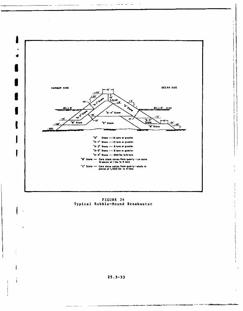
I
IHARBOR SIDE OENSD
II MALL.W / " g - " MLLW E0
*A St"e. -A- -'to-e a
'A' Stone - 16 tOns or greater.
'A-I" Stoe - 1S tons or greeter.
"A-" Stone - 8 tons or greater.I •'A-3" Stone4 - 6 tons o greater.
*A- 4* Stone - 50Q tiM. % tons.
*@* Stoe - Core stone varies from quarry- run stoneto pieces of I Ion to 4 ons.
"C" Slone - Core stone vories from quarry - waste topieces of 1,500 lb. to 4 tone.
FIGURE 24Typical Rubble-Mound Breakwater
25.5-53

(c) Cellular steel sheetpile construction. (SeeFigure 25.)
(2) Offshore types are:
(a) Rubble-mound structure for open ocean or bayexposure.
(b) Cellular steel sheetpile structure for less severeexposure.
(3) Other breakwater types include:
(1) Timber structure.
(2) Steel structure.
(3) Concrete sheecpile structure.
(4) Masonry block structure.
(5) Composite structures.
(6) Sand-filled sheetpile structure.
(7) Structure consisting of prefabricated concretecells set side by side and securely fastened together.
(8) Concrete superstructure built on a submergedrubble base.
(9) Perforated Swiss-cheese breakwater, which partiallydissipates wave energy in a chamber behind a perforated wall. (SeeFigure 26.)
f. Rubble-mound Construction.
(1) Dimensional Features. These are:
(a) Armor stone size and slope of primary cover layer.
(b) Crest elevation.
(c) Crest width.
(d) Underlayers and core.
(e) Layer thicknesses.
(f) Bedding or filter layer, and its size and thick-ness.
25.5-54

R~ lI
a
4 .1
CLu
25.5-5

60*-* - ~ 6~relief holeEl. 25,0 VOdPffoac.4d crushed store
s0cuppei L..
El 150 - Steel grating air relef hole FehM1*
8 Wove Chamber & Qar
Run Fill
________ 3'-d"# Woes, l"chamnfer t ender
49~ ~ 4 Dri hls oeo
4* <#Dmin jole 0j+ -
590 13
cfL FIGURE 26
Typical Swiss-cheese Perforated Breakwater Construction
25. 5-56

(2) Construction Factors. Consider the following:
(a) Integrity of a rubble-mound breakwater is largelydependent on the stability of the stones and armor units of whichit is built.
(b) Toe of a rubble-mound structure in water shallowerthan about twice the design wave height may be subjected to severescouring currents caused by wave turbulence. Bedding layer shall becarried well beyond the toe stones.
(c) The bedding layer and internal layers of smaller-stone sizes shall be placed before the armor layer is installed.
(d) To minimize danger of massive wave overtoppingof rubble-mound breakwaters, the crown shall be three or four armorunits wide and the units on the back slope down to about wave-heightdistance below the surface should be as large and as well placed asthose on the front slope.
(e) If a rubble breakwater is too porous, it willallow transmission of a high percentage of the longer-period waveenergy through it, and excessive wave disturbance will occur withinthe interior channels, and berthing basin and areas.
g. Design Details. For analysib and design details, referto Shore Protection Manual, Volume II and DM-26.1 a'ld DM-26.2.
3. GROINS.
a. Purpose. Groins may be used to:
(1) Build or widen a beach by trapping littoral drift.
(2) Reduce the rate off longshore transport out of an areaby reorienting a section of the shoreline to an alignment morenearly perpendicular to the predominant wave direction.
(3) Reduce loss of material out of an area by compart-menting the beach.
(4) Prevent accretion in a downdrift area by acting as alittoral barrier.
(5) Stabilize a beach, subject to excessive storms orseasonal periods of advance and recession, by reducing the rateof loss.
25.5-57
I

b. Types, These include:
(1) Timber groins.
(2) Steel groins.
(3) Concrete groins.
(4) Rubble-mound groins. (See Figure 27.)
(5) Asphalt groins.
c. Design Criteria. These are the same as for breakwater de-sign. For details, refer to DM-26.2 and Shore Protection Manual,Volume II.
4. JETTIES.
a. Purpose. A jetty is a structure extending into the waterto:
(1) Direct or confine tidal flow into the channel or boatbasin.
(2) Prevent or reduce the shoaling of the channel bylittoral material.
(3) Protect the entrance channel from wave action and crosscurrents.
(4) Stabilize the inlet location.
b. Types. These include:
(1) Rubble-mound structure.
(2) Sheetpile structure. (See Figure 28.)
c. Details. Refer to Shore Protection Manual, Volume II andDM-26.1 and DM-26.2.
5. WAVE AND SURGE DISSIPATORS.
a. Purpose. These devices are often provided to reduce tur-bulence in the boat basin caused by wave energy and surge.
b. Typical Devices. Some typical devices are described below:
(1) A non-uniform array of large stones placed on a flatslope facing the outer entrance at the first turn in the entrancechannel.
25.5-58
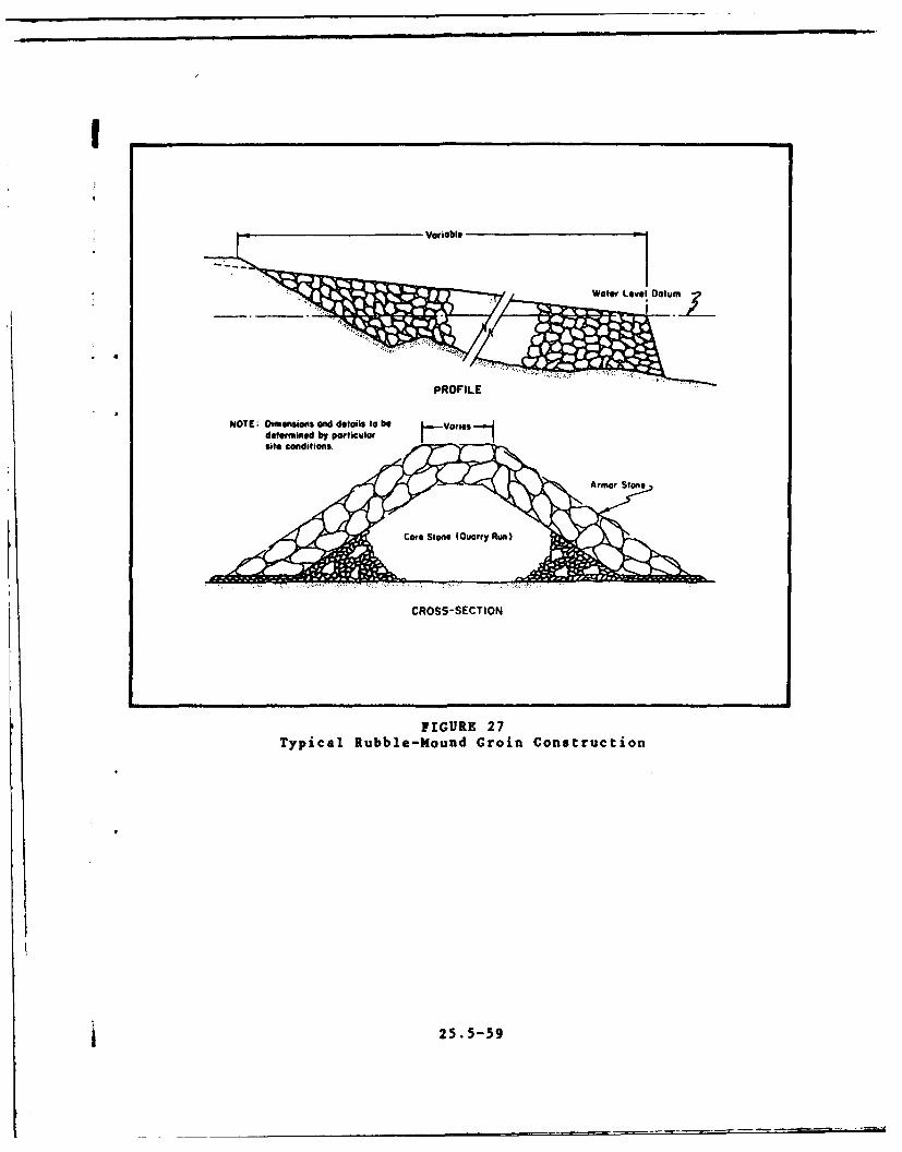
NOTE; Dimensions and details to be Variesdetermined by particularsite conditions.
CROSS-SECTION
FIGURE 27Typical Rubble-Mound Groin Construction
1 25. 5-59
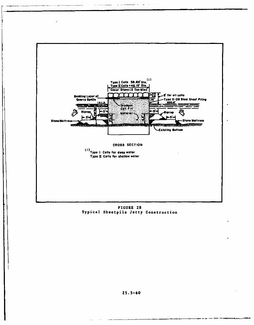
Type I Cells 58.81W Die.4Typs9Iels 4 .15 Dig.I Covar StoneS To(3 .
Quarry Spells 7r ~ Type S-28 Steel Sheet Piling
Ston MatressStone Mattress
Euisting Bottom
CROSS SECTION
I Type I Cells for deep waterType U Cells for shallow water
FIGURE 28Typical Sheetpile Jetty Construction
25. 5-60

(2) Wave-absorption beach, recessed in the elbow of thefirst bend in the channel.
4(3) Wave reflector, designed to reflect the waves back to-ward the first leg of the entrance channel.
(4) Combination of a trapezoidal channel-bed section andupper slopes roughened by large stones in the revetment.
6. BANK PROTECTION.
a. Protection. It is often necessary to protect banks fromwaves and currents in the channel. Protection installations include:
(1) Rubble layer placed on filter layer.
(2) Sheetpile or poured-in-place concrete wall at the topand a revetted slope from the toe of the wall to the channel bottom.
b. Details. See Shore Protection Manual, Volume II, fordetails.
7. RIVER PROTECTION. To berth boats directly in a river, the follow-ing methods can be used to provide protection to the berthing area.
a. Current Deflector Placed Upstream. This is built as a pile-dike fence inclined downstream, with heavy beams for horizontalmembers in the area of surface-level fluctuations to fend off float-ing debris.
b. Shallow Basin Excavated into the Riverbank. (See Figure 29.)
8. FLOATING WAVE ATTENUATORS. These are capable of reducing mode-rate waves to acceptable proportions. Types are:
a. Chained-log boom used mainly on rivers and small lakes.(See Figure 30.)
b. Floating breakwater of modular polyolefin pontoon unitssecured by timber stringers.
c. Wornout rubber tires secured together to form a continuousporous mass that floats just above the surface.
d. Air-filled mattress at the surface or suspended at somedistance below the surface to achieve out-of-phase damping.
e. Thin membrane on the surface to achieve viscous damping.
f. Random arrangements of horizontal pipes to destroy orbitalwave motion.
25.5-61
!'
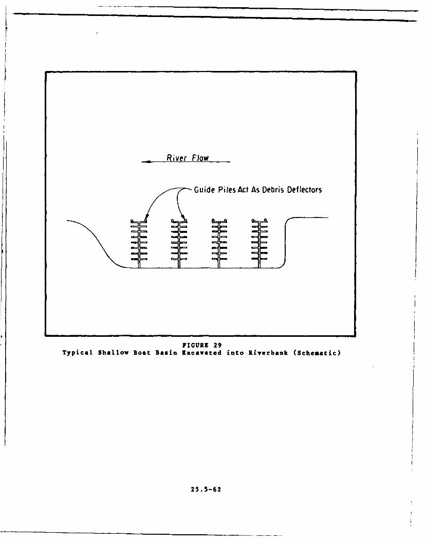
River Flow
Guide Piles Act As Debris Deflectors
FIGURE 29
Typical Shallow Boat Basin Excavated into Riverbank (Schematic)
25. 5-62

Anchors
FIGURE 30Typical Chained-Log loou for Short-Period Wave Attenuation
1 25. 5-63
g. Various solid structures with void patterns designed to breakup wave motion.
h. Series of vertical diaphragms.
Part 6. DESIGN CRITERIA FOR SUPPORT FACILITIES
1. UTILITIES. For water and electrical systems, and sanitaryrequirements, refer to DM-25.2. The following additional utilitiesshall be provided:
a. An intercommunication system, such as a public address orpaging system with speakers located within easy hearing distanceof every slip and support facility.
b. A central telephone switchboard in the harbor administrationbuilding.
2. LOCKER BOXES AND FIRE EQUIPMENT.
a. Locker Boxes.
(1) Provide locker boxes for gear storage and for structuralsupport for fixtures.
(2) Locate boxes in the knees of floating systems or in someout-of-the-way spot on decks of fixed piers.
(3) Boxes shall be made of plywood, sheetmetal, or fiber-
glass.
b. Firefighting Equipment.
(1) Chemical firefighting equipment may be used, if war-ranted, and placed at 200-foot intervals along each main walk.
(2) Cabinets housing the equipment shall be painted red.
(3) Place fire-alarm boxes at convenient locations on ornear piers. Spacing shall conform to requirements of NFPA No. 87.
3. FUEL DOCKS AND PUMPOUT STATIONS.
a. Fuel Docks.
(1) Fuel docks must be rugged, support the fuel pumps, andtake aboard the lines from thn buried tanks ashore. !
(2) Floating systems shall require flexible fuel linesleading to the fixed lines installed in the dock.
25,5-64
I (3) Provide a quick-disconnect device at the high point ineach fuel line to prevent the siphoning of the storage tank contentsinto the basin in the event of a line break below the stored-fuellevel.
b. Pumpout Stations. Pumpout facilities are generally placedon or near the fuel dock so that fueling and pumpout can be accom-plished successively at the same place. However, the pumpoutstation should not be too close to the fuel pumps.
I 4. CLEATS AND FENDERS.
* a. General. Every dock or slip shall require a set of cleatsfor mooring lines and fenders to cushion the impact of moored ordrifting craft against the dock.
b. Cleats.
(1) Use cleats made of metal, either galvanized or of non-i corroding alloys, or hardwood.
(2) Provide cleats of 10- or 12-inch length for boats upto 40 feet long, and 16 and 20 inches long for craft up to 75 and100 feet long.
(3) Cleats shall be securely bolted to the framework withI through bolts rather than lag bolts.
(4) For cleat arrangement pattern, one cleat near the kneeand one at the end of a finger (on each side) shall serve boats upto 35 feet long. For larger craft, provide one additional cleatper side for each additional 30 feet or part thereof.
(5) If cleats are used on loading docks or fuel docksdesigned for breast mooring, they shall be sized for the largestcraft and spaced at about 15-foot intervals. Alternatively, pro-vide a continuous curb rail supported on blocks spaced at about 3feet apart for tying mooring lines.
(6) In a double-boat slip system, provide two cleats about3 feet apart secured to the edge of the headwalk and centeredbetween the two fingers.
c. Fenders.
(1) Fendering systems may include old rubber tires, dis-carded firehose, or hemp hawsers of makeshift quality for the bumperelements. Special synthetic extrusion or molded shapes are pre-ferred for small-craft dockage in floating systems.
25.5-65
1

(2) The preferred type of bumper stripping for the edge ofa finger or dock is a synthetic extrusion that runs along the topedge of the outside stringer with a lip extending over the top. Neo-prene and butyl rubber provide adequate weathering resistant andresilient bumper materials.
(3) Molded corner bumpers, also of synthetic extrusion,provide adequate protection for smaller craft. For larger craft,use corner wheels especially where the finger extends all the wayout to an interpier fairway (primarily on floating system).
(4) Plastic-tube vertical fenders, stretched between pointsof support or suspended from a top fastening with a heavy pendulumweight hanging below the lowest possible point of hull contact, arealso in use.
(5) Fendering of fixed piers shall usually run verticallyrather than horizontally. Most common fenders for fixed systems arevertical timbers spaced at 8- to 10-foot intervals along each sideof a finger pier. Size of timber shall range from 3 by 4 inches to8 by 8 inches depending on the size of the berthed craft.
(6) Lengths shall be determined by the need to extend upwardabove the highest part of a gunwale at extreme high water and toextend below the lowest rub strake at extreme low water.
(7) Pier attachments shall be adequate to resist any momentthat might be caused by cantilever bending loads up to the designmoment of the fender section.
(8) Bolt heads or nut-and-bolt ends shall be countersunkinto the fender pieces to avoid scoring of boat hulls.
5. LAUNCHING HOISTS, ELEVATORS, AND WAYS.
a. Types. Most common types of equipment used in connectionwith small-craft berthing facilities for transferring boats betweenland and water are listed below:
(1) Davits.
(2) Forklift trucks.
(3) Jib-boom cranes.
(4) Lift slips.
(5) Marine railways.
(6) Mobile cranes.
25,5-66

(7) Overhead rail launchers.
(8) Stiff-leg derricks.
(9) Straddle-truck boat hoist.
(10) Vertical-lift platforms.
b. General Characteristics.
(1) Davits are for smaller craft and lack the versatilityof other launching devices.
(2) Marine railways entail high cost and waste of space,and lack versatility.
(3) Mobile cranes, either truck-mounted or crawler-mounted,are justifiable only where used in conjunction with some ancillaryoperation requiring this equipment.
(4) Vertical-lift platforms are used mainly for craft largerthan 25 tons.
c. Functional Characteristics of Different Types.
(1) Forklift truck has a fork ladder with the capabilityof hyperextending down over a bulkhead wall to the depth requiredto place the forks under the hull of a floating boat. Forklifts arebest suited for small-craft harbor basins with small water levelfluctuation.
(2) Jib-boom cranes have relatively short reach of the boom
and are geared to a slower operation.
(3) Three types of lift ships are in use:
(a) The elevating work slip that raises the boat outof the water so that the hull may be washed or minor damages to hulls,rudders, and screws repaired. The boat remains on a cradle or in asling in raised position above the water only until the operationis completed.
(b) A pair of hoists that remains as part of the berth-ing facility holds the craft above the water while not in use.
(c) A fixed-framework hoist that will allow the wavesto pass through the supporting legs without overturning. It isused for berthing sites along large lakes or bayshores that cannotbe protected easily against wave action.
(4) Overhead-rail launchers, either monorail or duorail,function the same way as a straddle vehicle except that they arenot mobile. Overhead rail is pushbutton-operated.
25.5-67
(5) The stiff-leg derrick has the rotational problem ofthe jib crane and also requires greater operator skill, and a tag-line crew to control the craft while in the air. Derricks shall beinstalled for handling larger craft.
(6) Straddle-truck boat hoist is limited to the boat sizeand straddle clearance, and shall be used in conjunction with alaunching well or parallel piers. The hoist is completely mobile.
d. Typical Facility. Figure 31 represents a hoist-launchingfacility with dry storage.
6. LAUNCHING RAMPS.
a. Slope. Slope of the launching ramp ranges between 12 and15 percent. Few trailered boats can be launched with a ramp slopeflatter than 12 percent without submerging wheel hubs of the trailer.Many trailered boats cannot be launched with hub submergence even ona 15 percent slope. Use either a trailer-tongue extension orlaunch the craft with a hoist.
b. Surface.
(1) Ramp surface should be paved down to an elevation of3 feet below extreme low water to insure that trailers are notbacked over the lower end. The top should be rounded over on a20-foot vertical curve until it becomes nearly level at about 2feet above extreme high water.
(2) The wetted part shall be paved with portland cementconcrete.
c. Approach. Nondirectio.,al traffic circulation shall be pro-vided with sufficient maneuvering space, say, 50 feet by 50 feet,adjacent to the top of the ramp.
d. Bottom. Bottom of the ramp shall end in a level shelf ofloose gravel so that a vehicle losing brakes or traction would bestopped before sliding deeper into the water.
e. General Features.
(1) A single-lane ramp shall not be narrower than 15 feet,and a multiple-lane ramp should not have raised divider strips.
(2) Provide about 40 to 50 feet maneuvering room beyondthe top of the ramp on a gentle rampward slope of about 1 on 50 forproper surface drainage.
(3) Provide boarding docks, preferably, on each side ofthe ramp and extending out into or along the sides of the basin witha total boarding length of at least 50 feet along each ramp.
25.5-68
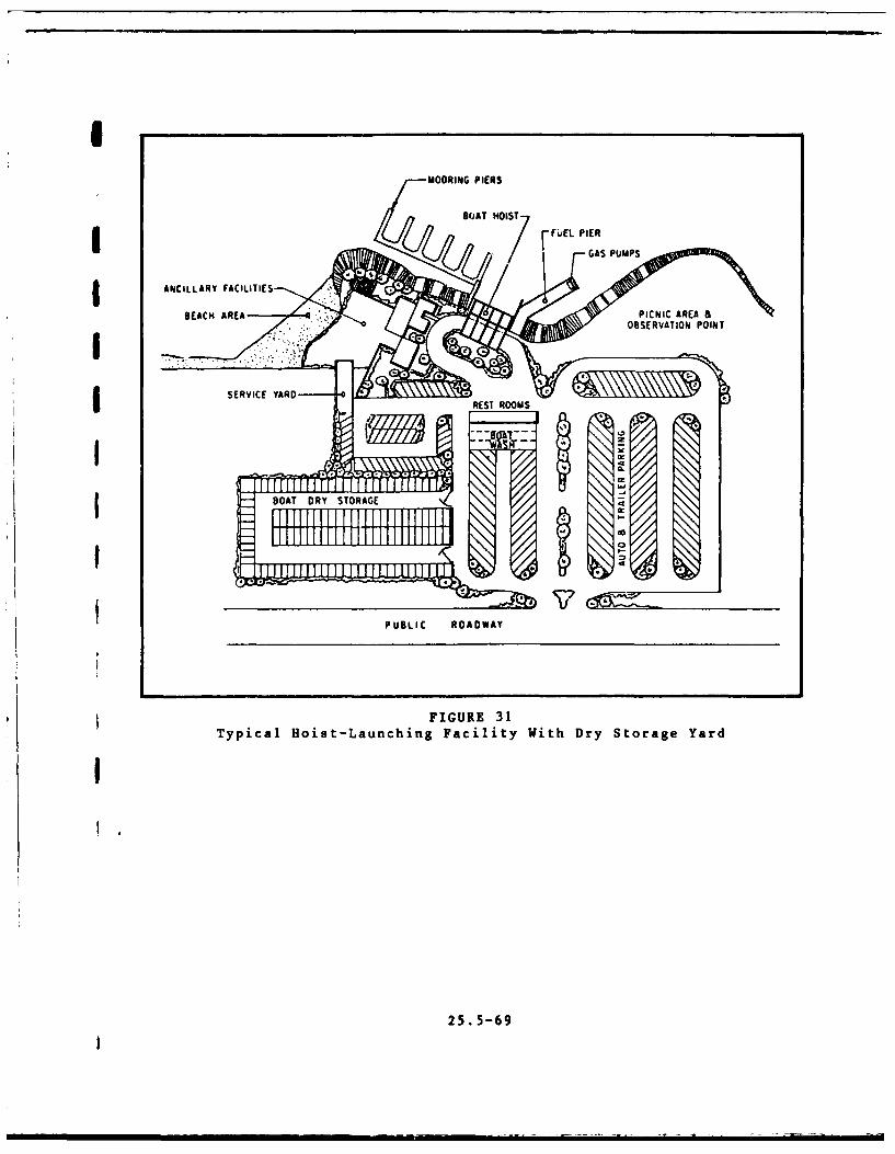
MOORING PIERS
I SERVICE YARD
PUBLI ROADWAY
FIGURE 31Typical Hoist-Launching Facility With Dry Storage Yard
25. 5-69
(4) Provide sufficient protected holding area in the waterjust off the ramp and boarding dock location for boats awaitingtheir retrieval turn during peak hours.
(5) Any part of the ramp that must be placed underwatershould be of precast sections. One method that has been used suc-cessfully is 6-by 12-inch precast slabs that are a lane-width long,spaced 3 inches apart, perpendicular to the slope, and the gapsfilled with gravel. Submerged ramps are also tremie-poured.
(6) Provide a conveniently located washdown facility forramps leading into saltwater or polluted waters.
f. Typical Layout. For layout of a typical launching rampfacility, see Figure 32.
7. SUPPORT BUILDINGS AND ANCILLARY STRUCTURES.
a. Administration Building. Two or three rooms should be pro-vided for a small installation and several rooms for headquarters ofa large-sized small-craft berthing facility. Functions and featuresto be handled are as follows:
(1) Clerical reception office with counter for transactingthe operational business and lounge space.
(2) Large record board dijp'aying a graphical layout of theberthing facility, number or letter description of each slip anddocking area, and the occupanc, status.
(3) Record files centairing facility maintenance records,utility service records, employee records, and fireproof vaultfor their safekeeping.
(4) Manager, harbormaster, or dock supervisor's office.
(5) Communication center for relaying incoming and outgoingcalls and operating the paging or public address system.
(6) Restroom facilities.
(7) Supplemental facilities, such as boardroom, coffee-break room or snack bar, engineering room, and storage room, follarge installations.
b. Maintenance Building and Yard for Storage. For typical lay-out, see Figure 33.
25.5-70
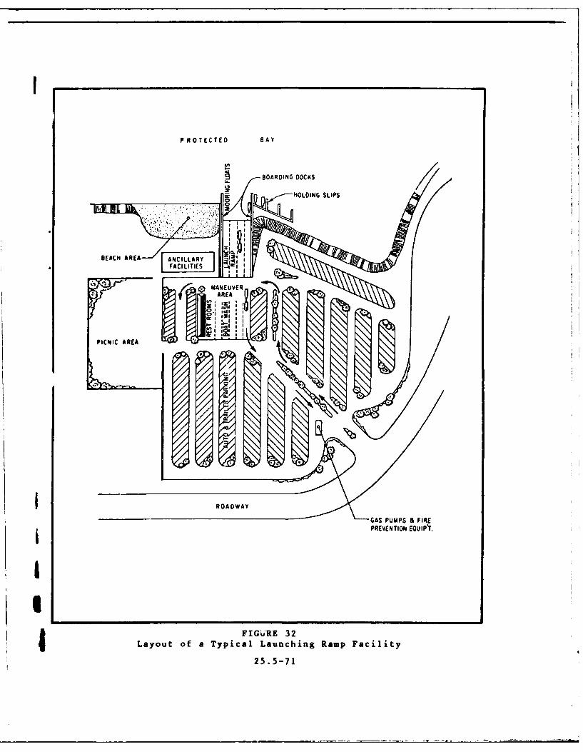
P ROT ECTED BAY
BOARDING DOCKS
I GASHOLDINGSSFIPE
PRVETOEEAIY
Ia
FIGVR:324 Layout of a Typical Launching Ramp Facility
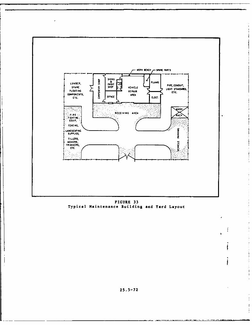
WORK BENCH/- SPAE PARTS
LUMBER, PLUMB.SAINT PIPE, CONDUIT,
SLO TIP 3 E I L LIGHT STANDARDS.COMPONENTS, AREA
ETC. ELECT.
LANCING
SUPPLIES,
TRIMMERS.,ta ETC. *
FIGURE 33Typical Maintenance Building and Yard Layout
25. 5-72

c. Boat Repair Facility. This is usually a part of, and imme-diately adjoining, a hoist or elevator. In small installations whereonly lighter craft are handled, four-wheel, castered dollys are usedfor transporting boats from retrieval areas to working area. Forheavier craft, large-capacity elevators are accompanied by a railsystem with a transfer pit for shunting boats on fixed-axle dollysfrom one track to another. A covered area with a gantry cranesshould be provided for performing engine and hull repair.
I d. Hardware Supply Store (Optional).
e. Transient Housing Facilities. These are restaurants, snackg bars, and recreational facilities.
f. Road and Walkway System. Adequate lighting shall be providedthat will insure smooth traffic circulation and pedestrian access toall the facilities in the harbor complex.
g. Layout of Utilities. Routing pattern for utility lines,storm drains, and sanitary sewers in the land area of the boatbasin complex.
h. Perimeter Fencing. Perimeter fencing shall be provided withlocked, entrance gates.
8. DRY STORAGE.
a. Purpose. Dry storage along with wet storage is needed forlack of sufficient space in protected waters or to keep craft drywhen not in use.
b. Storage Criteria. Dry storage shall be limited to boats notexceeding 2 tons. Sailboats under 16 feet shall be stored by hand,keel-up in racks. Powerboats under 24 feet shall be stored withforklifts, right side-up in racks. Larger powerboats and sailboatsshall be stored on special trailers or on adjustable cradle dollys.
c. Use Criteria. Consider the following:
(1) In saltwater areas, hulls of dry-stored boats should be
hosed with freshwater before storage.
(2) For launching small boats from dry storage, a hingedfloating ramp may be used. (See Figure 34.) The boat is placed on-a two-wheeled dolly, and then moved down the ramp until the wheelstrest against the bottom stop curb. The boat is then pushed off intothe water. Device is suitable for dinghys, small sailboats, andsmall outboards and where water level changes are not too great.
25.5-73
'

- .- Wheel Stop
FIGURE 34Typical Hinged Floating Launching Ramp
Used for Small Boats
25.5-74
9. SIGNS. The following signs are generally provided in a small craft
facility.
a. Welcoming sign at the entrance.
b. Direction signs where appropriate.
c. Signs designating buildings.
d. Signs for parking regulations, boat usage schedules, pierand slip designations, ramp and hoist use regulations, and sanitationand antipollution regulations.
Part 7. ENVIRONMENTAL FACTORS AND PROTECTION
1. SNOW.
a. Factors. Consider the following factors:
(1) In colder regions, floating-pier systems are seriouslyaffected by excessive snow loads. However, only the covered floatingberths are apt to be submerged by a heavy snowfall.
(2) Most roofs of floating sheds cannot be made steep enoughto insure that the snow will slide off. Roof area multiplied by 6times the anticipated maximum snow depth in feet will give the extraweight in pounds that is carried by flotation. If this exceeds thedesign live load, the amount of flotation should be increased suffi-ciently to support the difference without submergence of the flota-tion units.
b. Protection. Measures may include the following:
(1) Boats berthed in the open during the snow season incold regions shall be covered with tarpaulins, fitted canvas, orreinforced plastic covers.
(2) To protect against the submergence of floating systems,boats are removed from the water to dry storage before the winterseasons sets in. A common practice is to winter-store the largercraft on cradles on land and cover them. Smaller boats are generallystored keel-up for better shedding of snow and rain.
2. ICE.
a. Protection. Methods for reducing ice damage include:
(1) In regions where temperature drops are not excessiveand natural freezing does not cause a thick ice sheet, ice formationcan be prevented near piles and floating slips by forced convection
25.5-75
I
currents. This system is based on the principle that water reachesits maximum density at about 39oF. and tends to stratify in layerswith the heaviest on the bottom. Forced convection of this warmerbut denser water from the bottom to the surface when the surfacetemperature approaches 320 F. will prevent or at least postponefreezing.
(2) If a bubbler system is not used, sheet ice damage canbe reduced or prevented by proper design provisions. Piles aredriven deep enough in some materials to develop sufficient withdrawalresistance against lifting by ice. Flotation components of floatingsystems are designed with rounded or tapered bottoms.
(3) On rivers, estuaries, and lakes, the following measuresare often expedient:
(a) Pile clusters, often with sloping tops, are placedin the path of ice floes to break them up and divert them from theharbor basin.
(b) Breakwaters or jetties provide sufficient ice-impact protection.
(c) Deflecting booms made of logs or heavy timbersare used and sited to protect the berthing area from drifting ice.
3. HURRICANES.
a. Protection for Berthed Facilities. In regions where hur-ricane winds prevail, provide pile guides, and cable or chain-anchorage systems for floating docks. These are capable of accommo-dating design fluctuations of water level and resisting lateralwind forces.
b. Protection for Structural Components. Decking, roofs, andother major and minor provisions at dockage shall be anchored downor fastened together to prevent movement and possible collision withberthed craft or harbor structures.
c. Design Provisions. Use of hurricane-type shutters and avoid-ance of structural projection in the design of structural componentswould be expedient.
d. Emergency Precautions. Emergency precautions to avert orminimize the severity of hurricane damage and to prevent injuryinclude:
(1) Remove all loose or fragile items to a protected area.
(2) Open a door or window on the lee side of all buildingsto balance pressures.
25.5-76 I

U (3) Lash racked dinghys or other small, dry-stored boatsthat cannot be moved indoors.
(4) Disconnect all electrical appliances that are notneeded during the emergency.
craft. (5) Tighten or reinforce the mooring lines of all berthed
(6) Provide a system of lifelines for dock personnel whomust inspect the facilities during the storm.
4. OIL SPILLS.
a. If the harbor basin has a narrow entrance, releasing acontinuous curtain of air bubbles from the bottom all the way acrossthe entrance will keep the oil out.
b. Once spilled oil enters the basin, removal is accomplishedby employing floating booms, oil skimmers, and straw absorption.
5. FLOODS.
a. Nature of Damage. Flood damage, at harbor sites on or near
a river, is in the form of debris accumulation and collision offloating objects with structures.
b. Protection. Provide training wall as protection againstdebris and shoaling hazards.
Part 8. SUMMARY OF COMMON DESIGN PROBLEMS
1. PROBLEMS. Those problems most commonly reported for small-craftberthing facilities include:
a. Ice.
(1) Windblowing or movement by currents of ice floes con-stitutes a serious regional problem. Free-floating cake ice is thegreatest cause of ice damage.
(2) Where ice formation is anticipated, piles shall be
driven buttdown, if feasible.
(3) In a floating-pier system, the greatest damage is
caused by ice crushing the floats. Forced-convection or bubblersystems are effective for ice prevention.
25.5-77
b. Corrosive Environment.
(1) Failure of low-level lighting systems due to sea sprayin high wind conditions is a problem.
(2) Frequency of corrosion of water valves by seawaternecessitates the selection of T-Type faucet handles over the cir-cular type.
(3) Use of untreated wood for decking or structuralmembers of fixed piers.
c. Fufi Dispensiny.
(l) Fueling boats during extreme low water levels atfixed-pier stations.
(2) Reliability of fuel line connections to floating-pierstations.
d. Floating-pier Systems.
(1) Difficulty of adjusting chain or cable anchorages duringwater level fluctuation cycles and tendency of these systems to driftbeyond desirable limits.
(2) Time and difficulty involved in seasonal removal andstorage of floating systems at locations requiring winter security.
e. Shoaling of Channels and Basins.
(1) It constitutes a difficult maintenance-dredging problem.
(2) Detailed surveys of site bathymetry, suited to the site,should alwais be acquired.
f. Boa! -wake Problems. Enforcement of speed regulations forcraft operated near berthing areas is essential.
Section 4. DEGAUSSING AND DEPERMING FACILITIES
1. DEGAUSSING. This is the process by which a ship or boat, ora portion of the vessel, is equipped with a cable to neutralize thevessel's magnetic polarity by electric means as a protection againstmagnetic mines and, by the same token, to approximate the effect ofa nonmagnetic ship or boat. The cable is arranged around the hulland fed with a current of the correct magnitude to neutralize themagnetic effect of the hull. Continuous application of current,with adjustment to suit changes of position or heading of the craft,is required to maintain a degaussed condition.
25.5-78

2. DEPERMING. This process consists of removing, as far as feasi-ble, the permanent magnetic characteristics of a ship's hull by power-ful, external demagnatizing coils.
3. CRITERIA. Consult the sponsoring agency for criteria of de-gaussing and deperming applicable to any specific project.
4. REQUIREMENTS. Special facility requirements for degaussing anddeperming craft include:
a. Special electric power.
b. Strategic work areas for obtaining pertinent measurements.
c. Location will depend on site conditions and the locationof craft-berthing facilities.
25.5-79
i

REFERENCES
NAVFACENGCOM Design Manuals and P-Publications
DM-2.3 Structural Engineering: Steel Structures
DM-2.4 Structural Engineering: Concrete StructuresI DM-2.5 Structural Engineering: Timber Structures
DM-4 Series Electrical EngineeringDM-5.3 Civil Engineering: Drainage SystemsDM-5.4 Civil Engineering: PavementsDM-5.7 Civil Engineering: Water Supply SystemsDM-8 Fire Protection EngineeringDM-22 Liquid Fueling and Dispensing Facilities£ DM-25.1 Piers and Wharves
DM-25.2 Dockside Utilities for Ship ServiceDM-25.4 Seawalls, Bulkheads, and QuaywallsDM-25.6 General Criteria for Waterfront Construction
DM-26.1 HarborsDM-26.2 Coastal ProtectionDM-26.6 Mooring Design Physical and Empirical DataP-401 Pontoon Gear Handbook
Government agencies may obtain Design Manuals and P-Publicationsfrom the U.S. Naval Publications and Forms Center, 5801 Tabor Ave.,
Philadephia, Pa. 19120. TWX: 710-670-1685, AUTOVON: 442-3321.The stock number is necessary for ordering these documents and
should be requested from the NAVFACENGCOM Division in your area.
NON-Government organizations may obtain Design Manuals and P-Publi-cations from the Superintendent of Documents, U.S. GovernmentPrinting office, Washington, D.C. 20402.
Construction and Protection of Piers and Wharves, NFPA No. 87,National Fire Protection Association, 470 Atlantic Avenue, Boston,Massachusetts 02110.
AWPB Standard MPL for Softwood Lumber, Timber and Plywood PressureTreated for Marine (Saltwater) Exposure, American Wood PreserversBureau, P.O. Box 6085, 2772 S. Randolph Street, Arlington,Virginia 22206.
Reinforced Plastic Landing Float and Brow, Naval Civil EngineeringLaboratory Technical Report NCEL R605, available at The National
Technical Information Service, Springfield, Virginia 22151.
Shore Protection Manual Volumes I, II, and III, U.S. Army Coastal
Engineering Research Center, 1977, available at the U.S. Govern-ment Printing Office, Washington, D.C. 20402.
Port Engineering, by Bruun, P., 1976, Gulf Publishing Co., Houston,Texas
Reference-l

Design and Construction of Ports and Marine Structures, by Quinn,
A.D., Second Edition, 1972, McGraw-Hill Book Company.
Seismic Design of Piers, Volumes I, II, and III, 1976, TUDOR/PMBConsulting Engineering, August 1976, Naval Facilities Engineering
Command, Alexandria, Virginia 22332.
Report on Small Craft Harbors, ASCE-Manuals and Reports on Engi-
neering Practice-No. 50, 1969, 345 East 47th Street, New York, N.Y.10017.
Ports' 77, Volumes I and II, 4th Annual Symposium of the Waterway,Port, Coastal and Ocean Division of ASCE, 1977, 345 East 47thStreet, New York, N.Y. 10017.
Small Craft Harbors: Design, Construction, and Operation (SR-2),U.S. Army Coastal Engineering Research Center, December 1974,available at the U.S. Government Printing Office, Washington, DC20402.
Marinas: Recommendations for Design, Construction and Maintenance
by Chaney, C.A., 1961, National Association of Engine and BoatManufacturers, Inc., Greenwich, Connecticut.
Marina Operations and Service, 1961, National Association ofEngine and Boat Manufacturers Inc., Greenwich, Connecticut.
Military Specification MIL-P-40619, Plastic Material, Cellular,Polystyrene (For Buoyancy Applications) available at the U.S.Government Printing office, Washington, DC 20402.
Definitive Designs for Naval Shore Facilities, NAVFAC P-272, NavalFacilities Engineering Command, Alexandria, Virginia 22332.
Reference-2

GLOSSARY
Accretion. May be either natural or artificial. Natural accretionis the buildup of land, solely by the action of the forces ofnature, on a beach by deposition of waterborne or airbornematerial. Artificial accretion is a similar buildup of land suchas that formed by a breakwater, jetty or groin. Also Aggradation.
Anchor Pile. A pile or column that is an integral part of waterfrontstructure, whose primary function is to keep the structure firmlyin place, having been driven into earth for this purpose.
Ancillary Facilities. Installation or services provided at a harborsite that complement the harbor's operations, but are not essen-tial to harbor functioning per se.
Apron. Clear area around perimeter of a dock for access, parking,storage, and working space.
Armor. An outer layer of large stone or concrete armor units whosefunction is to insure the integrity of an embankment, jetty, orbreakwater for protection against wave action or currents.
Attenuate. To lessen the amplitude (magnitude of the displacementof a wave from a mean value) of waves or surge.
Auxiliary Power. Means of propelling a craft that is not the pri-marily designed means, e.g., an engine-driven propeller on asailboat.
Bank. The rising ground bordering a river, lake, or sea; of a riveror channel, designated as right or left as it would appear facingdownstream.
Basin, Boat. A naturally or artifically enclosed or nearly enclosedharbor area for small craft.
Bathymetry. The measurement of depths of water in seas, lakes oroceans; also information derived for such measurements. Also,Hydrography or Soundings.
Beach. The zone of unconsolidated material that extends landwardfrom the low water line to the point where there is marked changein material or physiographic form, or to the line of permanentvegetation. The seaward limit of a beach, unless otherwisespecified, is the MWL.
Beach Erosion. The carrying away of beach materials by wave action,tidal currents, littoral currents, or wind.
Bearing Boards. The wooden members that transmit the deck loadsto the floats in some floating-pier systems.
Glossary-i
Bedding Layers. The first and the lowest layer of gravel or stonethat acts as a bearing layer for larger stones or armor unitsplaced upon it. It also functions as a filter layer for thematerial beneath the structure.
Berm. A nearly horizontal part of the beach or backshore formed bythe deposit of material be wave action. Some beaches have noberm; others have one or more.
Berth. Area where a boat may be secured to a fixed or floatingstructure and left unattended.
Berthina Area. Area of a harbor set aside for berthing boats(vessels) at docks and/or open anchorages.
Boat. Any type of surface craft that may be berthed in a small-craftharbor.
Breakwater. A structure protecting a shore area, harbor, anchorageor basin from waves.
Brow. A type of bridge providing access to a berthed boat or vesselfor embarking and disembarking personnel.
Bulkhead. A structure designed to retain or prevent sliding of earthand consisting of a vertical wall, sometimes supplemented by ananchor system. A secondary purpose is to protect the uplandagainst damage from wave action.
Bulkhead Line. A line which establishes limits outside of whichcontinuous solid-fill construction is not permitted.
i _y. A float, especially a floating object moored to the bottomto mark a channel, anchor, shoal, roc ., etc.
Cantilever. A projecting beam, pile, or structural member thatresists or is capable of resisting a transverse load appl4ed tothe part projecting beyond its last point of support.
Cap. The finished structural member topping off a wall or bulkhead,providing strength, protection, and continuity to the wall orbulkhead.
Cleat. A wooden or metal mooring fitting having two diverqii,izontal arms to which mooring lines from boats are attacht,
Cofferdam. A temporary wall which serves to exclude watvrsite normally under water so as to facilitate foundatinstallation or similar work.
Current. A flow of water.
Davit. A device for raising, storing, and lowi.,
Glossary-2

AD-AI].9 526 NAVAL. FAC|L I I I . [[EE N i COAN4O AL.[KANARA VA P IR 13 1FERRY TERNINALS AND SMALL CRAFT BERTHING FACILZIES. OESIZN MAN--ETC(U)JUL. SI
JCLASSIFIEO NAVFAC-DW-25.S NL
2f 2
Diaphragm Breakwater. A comparatively thin, impervious wall,membrane, or structure designed to resist wave penetration,usually a secondary defense structure.
Dock. A fixed or floating decked structure against which a boat maybe berthed either temporarily or indefinitely.
UDolphin. A cluster of batter pilings joined at the top, and placednear piers and wharves, or alongshore, to guide vessels into theirmoorings; to fend boats away from structures, shoals, or theshorer and for anchorage of floating piers.
Downdrift. The direction of predominant movement of littoralmaterials.
Draft. Depth of craft hull below the waterline.
Eddy Current. A circular movement of water formed on the side ofa main current. Eddies may be formed at points where the mainsteam passes projecting obstructions or where two adjacent cur-rents flow counter to each other.
Estuary. (1) The part of a river that is affected by tides.
(2) The region near a river mouth in which the freshwaterof the river mixes with the saltwater of the sea.
Fairway. Parts of a waterway that are open and unobstructed fornavigation.
Fender. A protective bumper or framed system placed against the edgeof a dock, designed to prevent damage caused by impact of berthingor berthed boats.
Filter. The underlayer of small rock or gravel or sand that permitsproper seepage and dissipation or distribution of water beneathor behind a structure wall or riprap slope without allowing theearth or there retained material to escape.
Finger Pier. A smaller pier structure attached (usually perpendic-ular) to the headwalk of a multislip pier; provided to facilitateaccesss to the berthed craft.
Freeboard. The distance from the waterline to main deck or gunwale.
Gangway. A pedestrian or handcart bridge affording access fromshore or shore-connected fixed pier to a floating structure(sometimes called brow).
Groin. A shore protection structure built, usually perpendicularto the shoreline, to trap littoral drift or retard erosion ofthe shore.
Glossary-3
I. ... . .....
Guide Piles. Piles in a floating dock system that resist the hori-zontal displacement of the system but allow and guide its verticalmovement with changes in the level of the water surface.
Gunwale. The upper edge of the side of a ship or a boat.
Harbor. A sheltered area of the sea or ocean, easily accessible tomaritime routes in which vessels may seek refuge, transfer cargo,and undergo repair and refueling.
Headwalk. The main walkway on a multislip pier; supports utilitylines, lighting system, firefighting equipment, and locker boxes.
Hurricane. Intense tropical cyclone in which winds spiral inwardtoward a low-pressure core with maximum surface wind velocitiesthat equal or exceed 80 mph (70 knots) for several minutes orlonger at some points.
Jetty. On open seacoasts, a structure extending into a body of water,and designed to prevent shoaling of a channel by littoral pro-cesses, and to direct and confine the stream or tidal flow. Jettiesare built at the mouth of a river or tidal inlet to help maintainand stabilize a channel.
Keel. The principal bottom structural element of a craft extendingalong the centerline for the full length of the craft.
Lee. (1) The part or side sheltered or turned away from wind orwaves.
(2) The quarter or region toward which the wind blows(chiefly nautical).
Leeward. The direction toward which the wind is blowing; thedirection toward which waves are traveling.
Littoral Drift. The sedimentary material moved in the littoral zoneunder the action of waves and currents.
Littoral Transport. The movement of littoral drift in the littoralzone by waves and currents. It includes movement parallel (long-shore transport) and perpendicular (on-shore transport) to theshore.
Operational Launching. Boat launching on a routine in-and-out basisas distinguished from initial or seasonal launching.
overtopping. Flow of water over the top of a structure, such as abreakwater, as a result of wave runup or surge action. a
Pier. A dock that is built from the shore out into the harbor andused for berthing and mooring craft (a structure, usually, ofopen construction).
Glossary-4

Profile, Beach. The intersection of the ground surface with avertical plane; may extend from the top of the dune line to theseaward limit of sand movement.
Pumpout Station. A facility for removal of sanitary wastes from aboat's holding tank or head.
Revetment. A facing of stone, concrete or other material built toprotect a scarp, embankment, or shore structure against erosionby wave action or currents.
Riprap. A layer, facing, or protective mound of stones randomlyplaced to prevent erosion, scour, or sloughing of structure orembankment; also the stone so used.
Riser. A vertical pipe, post, or support extending above deck levelto support utility outlets and other facilities.
Rub Strake. A longitudinal rib or protective strip running alongthe hull of a craft to function as a bumper.
Rubble Mound. A mound of random-shaped and randomly-placed stonesprotected with a cover layer of selected stones or speciallyshaped concrete armor units.
Runup. The rush of water up a structure or beach on the breakingof a wave. The magnitude of runup is the vertical height abovestillwater level that the rush of water reaches.
Scend. The sinkage of a craft in the trough of a wave.
Screw. A propeller on any type of craft.
Sheetpile. A pile with a generally flat cross-section to be driveninto the ground or seabed and meshed or interlocked with likemembers to form a diaphrahm, wall, or bulkhead.
Shoreline. The intersection of a specified plane of water with theshore or beach.
Shoal. Become shallow gradually (v.). A detached elevation of thesea-bottom comprising any material except rock or coral, and whichmay endanger surface navigation (n.).
Slip. A space between two piers for craft berthing.
Small Craft. Shallow draft vessels such as work boats, rescueboats, harbor and pilot launches, special service craft, andsurvey boats.
Squat. The vertical downward displacement of a craft under powerwith respect to its position in the water when not underway.
Glossary-5
~~~~~I aa II II. .. . . .. . . . .. -

Stringer. The relatively long, main horizontal beam that supports thedeck of a fixed pier or dock between bearing points. In a floatingstructure, the continuous beam (usually, along the sides) that joinsa series of floating modules.
Surge. Wave motion with a period intermediate between that of theordinary wind-generated wave and wave caused by tide, say, from30 seconds to 60 minutes. It is of low height, usually lessthan 0.3 feet.
Swell. Wind-generated waves that have traveled out of their generat-ing area; characteristically represents a more regular and longperiod and has flatter crests than waves within their fetch.
Tidal Range. Difference in height between consecutive high and lowwaters.
Tide. Periodic rise and fall of the water that results from gravi-tational attraction of the moon. and sun, and other astronomicalbodies acting upon the rotating earth.
Trailing Floating Slips. Floating (usually, multiboat) slips thatalign themselves with the prevailing river current. They do notrequire guide piles.
Training Wall. A wall or jetty designed to direct or stabilizecurrent flow.
Transfer Bridge. A short-span bridge between boat and dock for trans-fer of railroad cars and other vehicles.
Tremie-youred Concrete. Concrete placed underwater in such a mannerthat there is no free drop of the concrete through the water.This is accomplished by pouring through a pipe or placing withspecial bottom-dump bucket.
Uplift. The upward water pressure on the base of a structure.
Waterline. The plane where land and sea meet. This plane shiftswith tidal change or other fluctuations in the water level.
Wave Attenuation. Reduction of wave height or amplitude for anyreason as the wave is propagated from one area to another.
Wave Breaker. A device that absorbs a large amount of wave energywith respect to the amount it reflects or transmits.
Wave Energy. The theoretical capacity of a wave to do work.
Wharf . A dock oriented approximately parallel to shore and used forberthing or mooring craft.
jGlossary-6
_I

F ATE
LME