fest the iter diagnostic residual gas analyzer ... documents/2010_08... · the iter diagnostic...
TRANSCRIPT

The ITER Diagnostic Residual Gas Analyzer - Requirements and Design Concept
Walt Gardner
FEST Seminar
2 August 2010

Walt Gardner 2 August 2010 2
• Requirements
• Conceptual Design
• Status and opportunities
Outline

Walt Gardner
Introduction
• The Diagnostic RGAs are listed in the ITER Project Requirements document (IDM 27ZRW8) as Group 1a2 diagnostics: Group 1a2 includes those measurements needed for basic machine control.
• Their purpose is to measure gas composition in the main chamber and Torus pumping ducts
2 August 2010 3

Walt Gardner
Measurement Requirements
• Sample gas in pumping ducts (divertor exhaust) and main vessel
• Measure fuel ratios, He, and impurities
• Mass range: 1 – 100 amu (emphasis on lighter gases)
• Resolution: 0.5 amu or better
• Pressure range: ( 1 – 1E-04) x Pmax [20 Pa in divertor duct or ~100 x less in main chamber]
• Time response (sample aperture to RGA detector): <1 s for pumping duct; <10 s for main chamber
• Accuracy: <20% pumping duct; <50% main chamber
2 August 2010 4
Walt Gardner 15-July-2010 5
• The main conditions affecting Diagnostic RGA equipment operation: - Magnetic field: Expected maximum magnetic
field levels in the Divertor and Equatorial port cells is ~150mT*. The DRGAs shall be shielded against this maximum value to the extent they will meet their measurement requirements. - Radiation field: The DRGA equipment and
components in the port cells shall be designed to operate at radiation doses up to [TBD] GY
Design Basis Conditions
* See for instance magnetic_field_map__plan_view_32HFEK_v1_0[1]

Walt Gardner
Design Basis - Locations • 3 Divertor Duct locations (Ports 6, 12, 18)
• 1 Equatorial Port Location (Port 11)
2 August 2010 6
12
6
18
Sampling this area of duct each location

Walt Gardner
System Boundaries and Interfaces • PBS 55.G4 (Diagnostic RGA) has an interface with PBS 15 (Vacuum Vessel) where
Divertor DRGA sample tube penetrates the VV vacuum envelope.
• PBS 55.G4 (Diagnostic RGA) has an interface with PBS 23 (Remote Handling Equipment), in that the system shall be located such as to not interfere with travel of a RH cask in the port cell.
• PBS 55.G4 (Diagnostic RGA) has an interface with PBS 24 (Cryostat and VVPSS) where Divertor DRGA sample tube penetrates the Cryostat vacuum envelope.
• PBS 55.G4 (Diagnostic RGA) has an interface with PBS 26 (Cooling Water System). Divertor DRGA sample tubes will need cooling water to provide required temperatures for baking and operations.
• PBS 55.G4 (Diagnostic RGA) has an interface with PBS 31 (Vacuum Pumping). In particular the DRGAs are pumped by Type 2 Diagnostic Vacuum Pumping Systems. Note that the DRGAs will produce tritium exhaust, but this is an interface between PBS 31 & 32.
• PBS 55.G4 (Diagnostic RGA) has an interface with PBS 43 (Steady State Electrical Power Network). Diagnostic equipment in the port cells and the diagnostics building will require electrical power.
• PBS 55.G4 (Diagnostic RGA) has an interface with PBS 44 (Cable tray infrastructure). Diagnostic cables will lie in cable trays.
• PBS 55.G4 (Diagnostic RGA) has an interface with PBS 45(CODAC). Diagnostic control and data retrieval will be done through CODAC. Data storage for all diagnostics is to be provided by CODAC.
• PBS 55.G4 (Diagnostic RGA) has an interface with PBS 46(Central Interlock system). Diagnostic signals will be used as input for the central interlock system. Interlocking of isolation valves will be required. 15-July -2010 7

Walt Gardner
• PBS 55.G4 (Diagnostic RGA) has an interface with PBS 48 (Central Safety System).
• PBS 55.G4 (Diagnostic RGA) has an interface with PBS 58 (Port Plug Test Facility). The Equatorial DRGA sample tube will interface with Equatorial port plug 11.
• PBS 55.G4 (Diagnostic RGA) has an interface with PBS 62 (Reinforced concrete buildings). The DRGA equipment will be located in port cells and galleries of the tokamak building.
• PBS 55.G4 (Diagnostic RGA) has an interface with PBS 64 (Radiological protections). Personnel access will be required at times in port cells and other locations outside the bioshield.
• PBS 55.G4 (Diagnostic RGA) has an interface with PBS 65 (Liquid and gas distribution). The DRGA systems will require nitrogen for venting and compressed air for valve actuation.
• PBS 55.G4 (Diagnostic RGA) has an interface with PBS 66 (Radwaste treatment and storage). DRGA components may be replaced instead of refurbished during maintenance or repair.
• PBS 55.G4 (Diagnostic RGA) has an interface with PBS 67 (Hot Cell and Rad Waste). There may be a need to transfer a DRGA system to a hot cell for maintenance, repair, and/or calibration.
• PBS 55.G4 (Diagnostic RGA) has an interface with PBS 98.TS (External Services). This interface covers the Project Management aspects of identifying, coordinating, and controlling interfaces.
15-July -2010 8
System Boundaries and Interfaces 2

Walt Gardner
Design Requirements
• 2.1 General requirements
• 2.2 System specific requirements
• 2.3 Structural requirements
• 2.4 Mechanical requirements (including load conditions)
• 2.5 Seismic requirements
• 2.6 Fire protection requirements
• 2.7 Electrical requirements - 2.7.1 Power supply requirements
• 2.8 Grounding and Insulation requirements
• 2.9 Instrumentation and control requirements
• 2.10 Computer hardware and software
requirements
• 2.11 HVAC requirements
• 2.12 Vacuum requirements and vacuum classifications
• 2.13 Thermal management requirements
• 2.14 Electromagnetic requirements
• 2.15 Nuclear shielding requirements
• 2.16 Chemical requirements
• 2.17 Materials requirements
• 2.18 Manufacturing requirements
• 2.19 Construction requirements
• 2.20 Assembly requirements
• 2.21 Installation requirements
• 2.22 Testing and inspection requirements
• 2.23 Decommissioning requirements
• 2.24 Other services
15-July -2010 9

Walt Gardner 2 August 2010 10
• Requirements
• Conceptual Design
• Status and opportunities
Outline
Walt Gardner
Design concept – Pumping Duct RGA • Sampling aperture: 0.25-mm diam.
• Sampling tube: 100-mm diam.; ~7-m length
• RGAs (Two complementary types) - Quadrupole Mass Spectrometer (full mass range; poor D2/He resolution;
needs magnetic shielding) - Optical Penning Gauge* (good H, D, T, & He resolution/response; optical
emission species only)
• Turbomolecular drag pump - Magnetically shielded - Optical Penning sampling at intermediate stage to accommodate its
operating pressure range - Exhaust to Type 2 foreline
• Pressure gauges, isolation valves, baking, etc.
• Connection to Service Vacuum System - Venting/purging - Containment interspace monitoring
11 May 2010 11 * D. L. Hillis, et al., Rev. Sci. Instrum., Vol. 70, No. 1, January 1999

Walt Gardner
More on Mass Spec Analyzers
Quadrupole Mass Spec
Magnetic Sector
Electrostatic Ion Trap
http://www.brooks.com/pages/4074_simplicity_solutions_partial_pressure_instrumentation.cfm
2 –August -2010 Chris Klepper

Walt Gardner
Precedent on Continuous Mass-Spec DRGA on a Tokamak
• Tore Supra currently has a DRGA with a quadrupole mass spectrometer (magnetically + EMI) shielded for operation during plasma operation
• Continuous data acquisition and data transfer (15 channels/ 32ms)
• Have successfully used with shots up to 6 min [Recent HTPD-2010 paper/poster]
Uses commercial Balzers QMG-421 Mass-Spec
2 –August -2010 Chris Klepper

Walt Gardner
Dual Sensor Design (Mass Spectrometer and Optical Gas Analyzer)
• The Dual Sensor design (MS + OGA) allows each DRGA system to meet the measurement requirements MS provides 50 to 100 atomic/molecular masses to
be acquired simultaneously Existing models can be applied to the spectra to
resolve CO/N2, CD4/D2O OGA resolves He/D2 and can provide more direct
H2/D2/T2 measurement
2 –August -2010 Chris Klepper

Walt Gardner
OGA Concept and Current Use
• A Optical Gas Analyzer based on the Penning gauge discharge (« Penning Optical Gas Analyser » or Penning-OGA) is already in use on DIII-D, JET and Tore Supra.
– Originally developed to distinguish He from D2 (both M = 4)
– On DIII-D it also measures Ne/D2 and Ar/D2
– On JET it measures H2/D2 and T2/D2
– On Tore Supra it measures He/D2
• Neutral gas is excited by a local plasma discharge • The optical emission analysis gas composition.
2 –August -2010 Chris Klepper

Walt Gardner
Penning-OGA at JET with T runs*
* Hillis, et al., Rev. Sci. Instrum., Vol. 70, No. 1, January 1999
• OGA T2/D2 measurement is “self-calibrating”!
• JET study is best proof-of-principle for OGA on ITER
OGA: Uses commercial [no longer being produced] Alcatel CF2P Penning Gauge Tube
2 –August -2010 Chris Klepper

Walt Gardner
He/D2 even more critical for ITER’s OGA
This also from JET Divertor Penning-OGA
Earlier results with the Penning emission sampled with Dα and He I filtered detectors.
Change-over experiments with the the MkII-GB (gas box divertor configuration)**
This measurement is not possible with present QMS sensors
**D.L. Hillis et al. / Journal of Nuclear Materials 313–316 (2003) 1061–1065
Penning-OGA Data
2 –August -2010 Chris Klepper

Walt Gardner
ITER DRGA Component Diagram
2 –August -2010 Chris Klepper

Walt Gardner
Innovative Vacuum Interface
• MS and OGA sensors require different base pressures for optimal operation P(MS) <~ 1x10⁻³ Pa 5x10⁻² Pa < P(OGA) <~ 1 Pa
• Innovative vacuum arrangement and interface was developed to - Provide optimal sensor pressures - Minimize differential pumping stages - Avoid stagnation points - Meet time response requirements
2 –August -2010 Chris Klepper

Walt Gardner
Innovative Vacuum Interface
Optical Gas Analyzer Placed downstream from RGA chamber
• Having the primary RGA chamber at the lower pressures allowed for simpler (analytic) conductance calculations (molecular flow regime) and more certainty about meeting response time requirements.
2 –August -2010 Chris Klepper 2 –August -2010 Chris Klepper
Walt Gardner
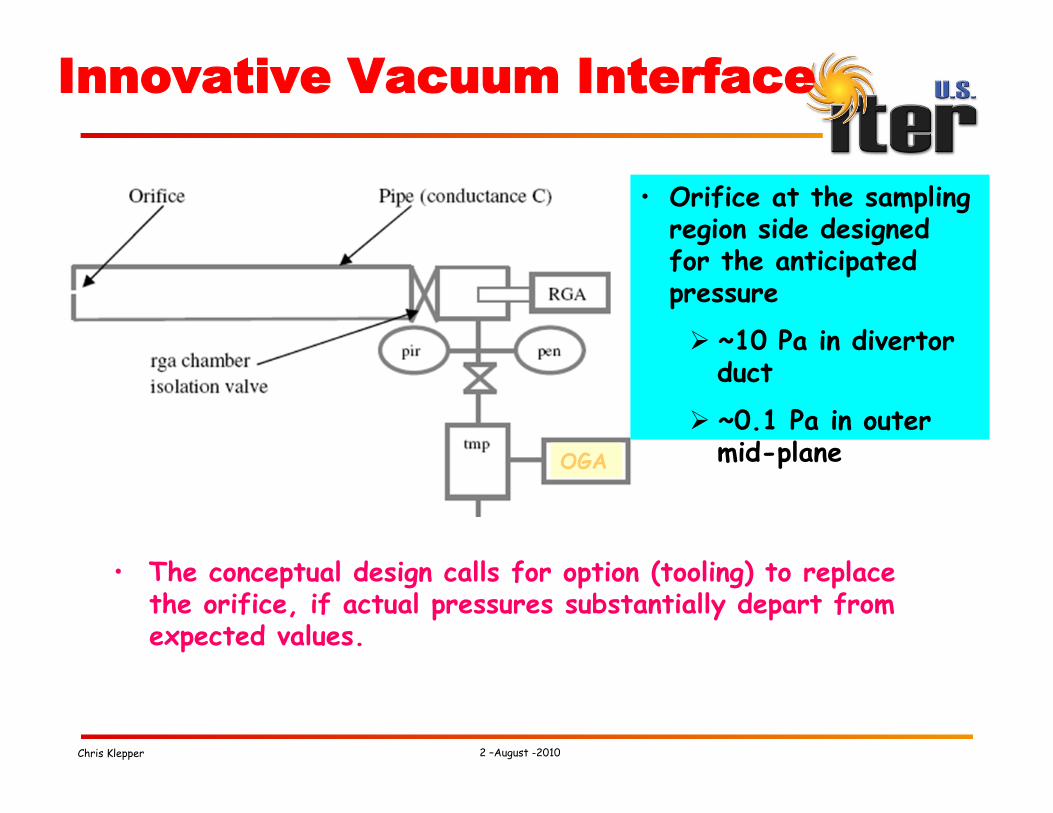
Innovative Vacuum Interface
• The conceptual design calls for option (tooling) to replace the orifice, if actual pressures substantially depart from expected values.
OGA
• Orifice at the sampling region side designed for the anticipated pressure
~10 Pa in divertor duct
~0.1 Pa in outer mid-plane
2 –August -2010 Chris Klepper

Walt Gardner
Response Time
• Present design allows for analytic calculations of response time (molecular flow regime)
2 –August -2010 Chris Klepper

Walt Gardner
Response Time
H2
D2 and/or He
CO
H2O
Present design is compatible with ~1s response time requirement
For the mid-plane RGA, ~identical design will provide same ~1s response time • 10x better than
requirement.
2 –August -2010 Chris Klepper

Walt Gardner
Accuracy and Calibration
• Calibration Plan: - Every RGA system will have its own calibration gas manifold - Gases injected directly into RGA chamber - Calibration procedures well documented in the published
literature.
• Accuracy: - Mass Spectrometer
• Expect 5-10% error in applying models to extract species concentration from multiple peaks
• Expect up to 5-10% error in applying total pressure from Penning gauge to get actual partial pressures (not an issue for ratios)
• Expect 5-10% error from interpolation between calibrations • Still consistent with 20-50% accuracy requirement
- Optical Gas Analyzer • 10-20% error is consistent in most visible-range plasma
spectroscopy experience.
2 –August -2010 Chris Klepper

Walt Gardner
Calibration System: Integral Part of Each DRGA System
2 –August -2010 Chris Klepper

Walt Gardner
External Error Sources
• Possible impact from external B-field: - Avoid with proper shielding; - Present design uses proven (on JET) magnetic shielding
technology • Attenuates the expected 150 mT fringing field down to 5 mT
considered safe.
• Tritium: - Beta-emitter; has been found to shift the MS spectra zero
level; can correct in the analysis • (Work by Robert Pearce, ref. in design documents)
• Neutrons and Gammas - New Rad-Hard MS model with RF source + control
electronics 15m away - MS analyzer unit accessible for replacement - Spectrally resolved detection of OGA signals can overcome
any scintillation issues in the optical fibers.
2 –August -2010 Chris Klepper

Walt Gardner
Manufacturability
• The DRGA systems will be manufactured from off-the-shelf equipment and readily available or easily fabricable components.
• System configuration will be designed for ease of assembly, installation, testing, and maintenance
• No hazard or availability issues are foreseen for choices of materials
• No issues are foreseen for compliance with ITER codes and standards
15-July-2010 27

Walt Gardner
DRGA System Schematic
2 August 2010 28
Baking and magnetic shielding not shown

Walt Gardner
Divertor Design Concept Model
2 August 2010 29
Main Torus Cryopump housing Branch duct
Aperture
RGA “chamber”
Pumping duct
Sampling tube

Walt Gardner
Configuration in divertor ports Sample gas at junction between branch pump and main pump
Main pump: on
Branch pump: off
2 –August -2010 Philip Andrew

Walt Gardner
Configuration in divertor ports Sample gas at junction between branch pump and main pump
Main pump: off
Branch pump: on
2 –August -2010 Philip Andrew

Walt Gardner
Divertor level
Main pumping duct
Branch pumping duct
Bio shield
2 –August -2010 Philip Andrew

Walt Gardner
Divertor level
RGA pipe 1 rigid piece
Bellows between cryostat vacuum extensions
Vacuum vessel & cryostat penetration
Same as divertor cooling water pipes
2 –August -2010 Philip Andrew

Walt Gardner
Divertor Design Concept Model
2 August 2010 34
Isolation Valves
Turbopump with magnetic shielding

Walt Gardner
Contents of RGA vacuum chamber
Isolation valve
Optical Penning Sensor
Isolation valves Turbo pump
Mass Spectrometer
RGA Chamber + pressure gauge
2 –August -2010 Philip Andrew

Walt Gardner
Configuration at equatorial port
Port plug Interspace
Port
2 –August -2010 Philip Andrew

Walt Gardner
Configuration at equatorial port
• Pipe built into port plug
• Exits back of port plug
Port plug Interspace
Port
RGA pipe
2 –August -2010 Philip Andrew

Walt Gardner
Configuration at equatorial port
Double bend in pipe inside port plug for neutron shielding
Pipe 1 rigid section. No bellows.
In port cell, support weight of pipe, but allow sideways movement (differential thermal expansion)
2 –August -2010 Philip Andrew

Walt Gardner 2 August 2010 39
• Requirements
• Conceptual Design
• Status and opportunities
Outline

Walt Gardner
Status • Conceptual Design Review held 15-16 July - A number of “chits” were issued that need to be resolved prior
to proceeding - Favorable response to design concept
• IO needs to work on - Safety and measurement classifications - Some required documents - Number of systems needed - Better definition of interface with vacuum pumping
• Design concept may need more work once IO has resolved its issues, but should be relatively minor
• Goal to have Procurement Arrangement in place in ~ 6 months
2 August 2010 40

Walt Gardner 15-July-2010 41
• New type of mass sensor could offer significant advantages over QMS - Full range mass scan in < 1s vs. 10s of seconds for QMS - Calibration at only one mass vs. several over full range - Perhaps less magnetic shielding needed because of full axial
trajectory geometry - Issue: untested (brand new on market)
• Placing Optical Penning Gauge diagnostic at intermediate stage of turbo pump - Should provide correct pressure regime for gauge operation
• Issue: untested - Alternative would be to place directly on foreline
• Issue: untested - Valve switching between two locations also under
consideration • Replaceable apertures in case pressure regimes significantly
different from expected - Issue: Only fixed aperture is in current design
Technical Opportunities & Issues
2 August 2010

Walt Gardner
Risk-mitigating R&D
• Development to consider to reduce technical risk* - Set up test stand in US or perhaps at Tore Supra - Test system main components, pumps, valves, and mass
spectrometers, in simulated environment to validate design - Would not fully mock up sample tubes (divertor and
equatorial) - Interchangeable sample tube lengths - Sample gas introduction chamber attached to sample
tubes - Removable aperture plates on standard flanges - Build in capability to try aperture replacement designs - Dual purpose to use for qualification of actual system
components
15-July-2010 42
*not currently in project plan 2 August 2010

Walt Gardner
Acknowledgements
• These folks are contributing the bulk of current effort – many thanks - Philip Andrew – ITER Responsible Officer for the
Diagnostic RGAs - Shaun Hughes – ITER Vacuum Group in charge of
Type 2 Diagnostics (recently of SNS at ORNL) - Chris Klepper – ORNL Fusion Energy Division on
assignment to Tore Supra and US Technical Lead at ITER for the Diagnostic RGA effort
• Thanks to Dave Johnson for supporting the US portion of this work
2 August 2010 43