fgv x manual - nidec-shimpo corporation · fgv-hx offers output capabilities. overload caution...
TRANSCRIPT


2
Physical Features
NO. DESIGNATION1. Sensor Shaft2. Low Battery Indicator3. Peak Indicator4. Main Display5. Small Display6. Peak Button7. Unit Button8. Tare and Zero Button9. Power (ON, OFF) switch
10. AC Adapter Port11. Data Output Port (FGV-HX only)12. Hanger
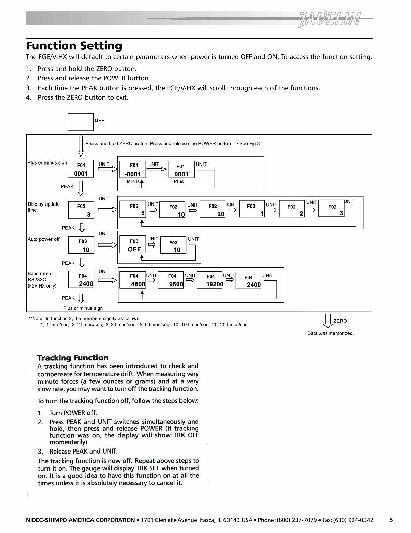
Factory SettingThe FGE/V-HX will revert to factory setting when thegauge is first powered on. Consult the Function Settingsection to customize these default settings.
The following chart reflects the default settings asprogrammed by the factory:
FUNCTIONFUNCTIONFUNCTIONFUNCTIONFUNCTION DEFDEFDEFDEFDEFAAAAAULULULULULT FT FT FT FT FACTORYACTORYACTORYACTORYACTORYNUMBERNUMBERNUMBERNUMBERNUMBER DESCRIPTIONDESCRIPTIONDESCRIPTIONDESCRIPTIONDESCRIPTION SETSETSETSETSETTINGTINGTINGTINGTING
f01 Plus or Minus sign 0001 (plus for compression)f02 Display update time 3 (3 times/sec)f03 Auto power off 10 (min)f04 Baud rate of RS-232C 2400 (bps)
Operation1. Charge the batteries for approximately 18 hours before
using the gauge (Batteries come discharged from thefactory). The BAT indicator is on when batteries arecharging, off when the batteries are fully charged.
2. Hand tighten appropriate attachment to unitsmeasuring shaft (do not use a wrench or any otherdevice to tighten the attachment).
3. Press POWER and release. The unit will display modelname in small display and capacity in main display andthen will show some zeros with the last one or twodigits changing to some random numbers. Also theunit of measurement (lb, Kg or N) will appear abovethe digits and stay as long as the instrument is on.
Change Display UnitsTo change the display units, just press UNIT and the unitswill change every time the button is pressed.
Reverse the DisplayIf unit is used with the hanger or mounted on a test standand the display must be reversed, follow this procedure:
1. Press POWER and hold it; display will go blank.2. Press and hold UNIT.3. Release POWER while you are still holding UNIT;
display is still blank.4. Press POWER once more and release it while still holding
UNIT. At this point you should see the display reversed.5. Release UNIT; the display stays in that mode.To go back to normal mode repeat steps 1 through 5.
Select Average or PeakIf you want to measure force in real time (average) thedisplay will show only the digits and units of the forcebeing measured. If you want to measure peak force:
1. Press PEAK; the word PEAK will appear in the upperleft corner of the display. (If you need a minus peak,press PEAK again.)
2. The display will freeze after capturing the peak force.3. Press ZERO to cancel previous peak and continue with
your tests.If you want to go back to average mode press PEAK again.The word PEAK will disappear from the display.
NOTE: It is very important that you measure forces(tension or compression) that are in line with themeasuring shaft and not at any angle (see figure 1).Failure to observe this directive will damage theinstrument. Also, after the gauge is positioned and readyto take a measurement (with the proper attachment inplace) tare the unit by pressing ZERO. To clear the displayfor another measurement (in PEAK mode), press ZERO.
lb ! N ! Kg !

3
Tension MeasurementTo measure tensile force, use the hook attachment. Thedisplay will show the force measured and a minus sign (-)will appear on the left of the display (to the left of thedigits).
NOTE: To display no sign (plus) for tensile force, consultthe Function Setting section.
Compression MeasurementTo measure compression force, use the flat headattachment. No sign will appear on the left of the displayduring a compression measurement.
NOTE: To display minus sign (-) for compression force,consult the Function Setting section.
Low BatteryWhen battery charge is low, LO BAT will appear on thedisplay indicating the batteries need to be charged.Charging time of fully depleted batteries is approximately18 hours when the unit is off. The adapter/chargerautomatically shuts off when the battery is at full chargeto protect the battery.
NOTE: The adapter/charger can be used to power the unitduring battery charging, but will lengthen charging time.
Auto Power OffIf the gauge is on and there is no activity for 10 minutes,the unit automatically powers off to conserve batterycharge. PWR appears above the display digits to notifythat there is 1 minute before power off. If the adapter/charger is powering the gauge, auto power off functionbecomes inactive.
NOTE: To modify the auto power off function, consultthe Function Setting section.
External Device CommunicationsWhen operated with the appropriate output cable, theFGV-HX offers output capabilities.
OverloadCaution should be exercised that overloads do not occur;sensor damage can result. To protect the gauge andsample under test when used with a motorized stand(or similar device), two built-in OC NPN transistors stopmotion when the gauge reaches 120% of its ratedcapacity. One transistor is for tension, the other forcompression (figure 2).
Analog OutputAn analog output signal is available for recordingpurposes. The amplitude of this signal is ± 1 VDC. Thevoltage is positive when compression testing is performedand negative for tension. The signal characteristics areas follows:
AmplitudeAmplitudeAmplitudeAmplitudeAmplitude ± 1 VDCGenerated byGenerated byGenerated byGenerated byGenerated by 12-bit D/A converterSignal updateSignal updateSignal updateSignal updateSignal update 100 times/sec (update every 10 msec)Load impedanceLoad impedanceLoad impedanceLoad impedanceLoad impedance 10 KΩ minimumConnector pinsConnector pinsConnector pinsConnector pinsConnector pins Pin #1 signal output (analog)
Pin #2 GND (analog)(see Fig.3 & Table 1)
NOTE: When the zero switch is pressed to tare the gaugethe analog output goes to 0V automatically.
Figure 1
Figure 2


7
Dimensions
TroubleshootingThe following are general checkpoints; please call your local Shimpo representative or contact Shimpo Instrumentsdirectly for further assistance.
The force gauge does not come on:
Check all electrical components (power source, charged battery or AC adaptor connected)
The stand does recognize the RS232 output/input:
Check all connections between the test stand and the force gauge and/or computer
Error codes are displayed:
Turn unit off, then back on. If error codes are still displayed, see table below:
Smal l displaySmal l displaySmal l displaySmal l display Condi tionCondi tionCondi tionCondi tion Acti onActi onActi onActi on
Minus side overload condition - possible load cell damage
Plus side overload condition - possible load cell damage
EEPROM reading error
EEPROM writing error
The load exceeds 120% of its capacity Remove excessive load
Remove excessive load; if the display does not return to normal operation, send unit in for repair
Turn off, then turn on again. If the display does not return to normal operation, send unit in for repair.
OVP
OV+
OV-
ERR- 4 -
OVM
ERR- 3 -
