fiber-optic products and applications data sheet
TRANSCRIPT
Schweitzer Engineering Laboratories, Inc. SEL Fiber-Optic Products and Applications
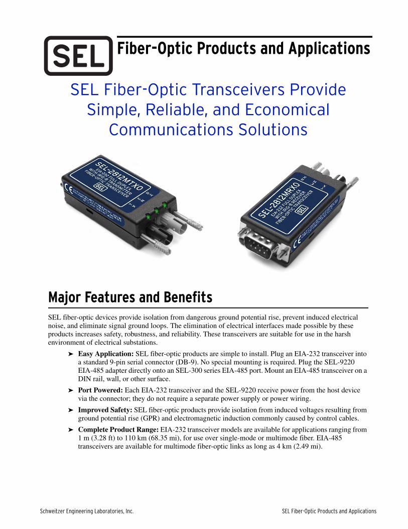
SEL Fiber-Optic Transceivers Provide Simple, Reliable, and Economical
Communications Solutions
Major Features and BenefitsSEL fiber-optic devices provide isolation from dangerous ground potential rise, prevent induced electrical noise, and eliminate signal ground loops. The elimination of electrical interfaces made possible by these products increases safety, robustness, and reliability. These transceivers are suitable for use in the harsh environment of electrical substations.
➤ Easy Application: SEL fiber-optic products are simple to install. Plug an EIA-232 transceiver into a standard 9-pin serial connector (DB-9). No special mounting is required. Plug the SEL-9220 EIA-485 adapter directly onto an SEL-300 series EIA-485 port. Mount an EIA-485 transceiver on a DIN rail, wall, or other surface.
➤ Port Powered: Each EIA-232 transceiver and the SEL-9220 receive power from the host device via the connector; they do not require a separate power supply or power wiring.
➤ Improved Safety: SEL fiber-optic products provide isolation from induced voltages resulting from ground potential rise (GPR) and electromagnetic induction commonly caused by control cables.
➤ Complete Product Range: EIA-232 transceiver models are available for applications ranging from 1 m (3.28 ft) to 110 km (68.35 mi), for use over single-mode or multimode fiber. EIA-485 transceivers are available for multimode fiber-optic links as long as 4 km (2.49 mi).
Fiber-Optic Products and Applications
2
SEL Fiber-Optic Products and Applications Schweitzer Engineering Laboratories, Inc.
Fiber-Optic Transceivers and Applications
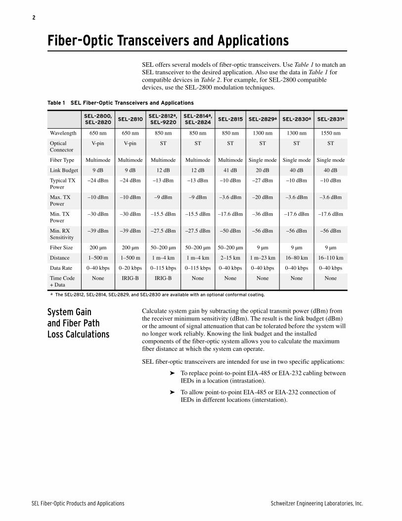
SEL offers several models of fiber-optic transceivers. Use Table 1 to match an SEL transceiver to the desired application. Also use the data in Table 1 for compatible devices in Table 2. For example, for SEL-2800 compatible devices, use the SEL-2800 modulation techniques.
System Gain and Fiber Path Loss Calculations
Calculate system gain by subtracting the optical transmit power (dBm) from the receiver minimum sensitivity (dBm). The result is the link budget (dBm) or the amount of signal attenuation that can be tolerated before the system will no longer work reliably. Knowing the link budget and the installed components of the fiber-optic system allows you to calculate the maximum fiber distance at which the system can operate.
SEL fiber-optic transceivers are intended for use in two specific applications:
➤ To replace point-to-point EIA-485 or EIA-232 cabling between IEDs in a location (intrastation).
➤ To allow point-to-point EIA-485 or EIA-232 connection of IEDs in different locations (interstation).
Table 1 SEL Fiber-Optic Transceivers and Applications
SEL-2800, SEL-2820
SEL-2810SEL-2812a, SEL-9220
SEL-2814a,SEL-2824
SEL-2815 SEL-2829a SEL-2830a SEL-2831a
Wavelength 650 nm 650 nm 850 nm 850 nm 850 nm 1300 nm 1300 nm 1550 nm
Optical Connector
V-pin V-pin ST ST ST ST ST ST
Fiber Type Multimode Multimode Multimode Multimode Multimode Single mode Single mode Single mode
Link Budget 9 dB 9 dB 12 dB 12 dB 41 dB 20 dB 40 dB 40 dB
Typical TX Power
–24 dBm –24 dBm –13 dBm –13 dBm –10 dBm –27 dBm –10 dBm –10 dBm
Max. TX Power
–10 dBm –10 dBm –9 dBm –9 dBm –3.6 dBm –20 dBm –3.6 dBm –3.6 dBm
Min. TX Power
–30 dBm –30 dBm –15.5 dBm –15.5 dBm –17.6 dBm –36 dBm –17.6 dBm –17.6 dBm
Min. RX Sensitivity
–39 dBm –39 dBm –27.5 dBm –27.5 dBm –50 dBm –56 dBm –56 dBm –56 dBm
Fiber Size 200 µm 200 µm 50–200 µm 50–200 µm 50–200 µm 9 µm 9 µm 9 µm
Distance 1–500 m 1–500 m 1 m–4 km 1 m–4 km 2–15 km 1 m–23 km 16–80 km 16–110 km
Data Rate 0–40 kbps 0–20 kbps 0–115 kbps 0–115 kbps 0–40 kbps 0–40 kbps 0–40 kbps 0–40 kbps
Time Code + Data
None IRIG-B IRIG-B None None None None None
a The SEL-2812, SEL-2814, SEL-2829, and SEL-2830 are available with an optional conformal coating.
3
Schweitzer Engineering Laboratories, Inc. SEL Fiber-Optic Products and Applications
Intrastation Fiber Optics
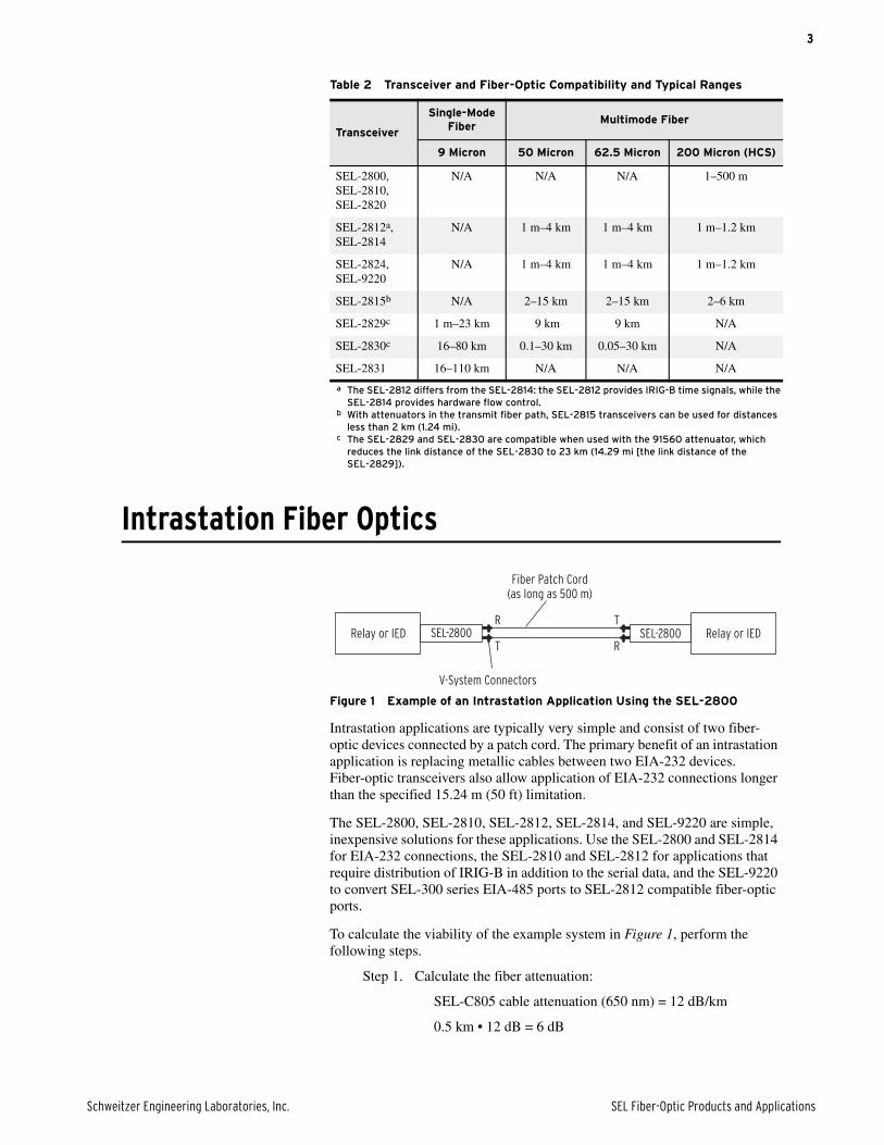
Figure 1 Example of an Intrastation Application Using the SEL-2800
Intrastation applications are typically very simple and consist of two fiber-optic devices connected by a patch cord. The primary benefit of an intrastation application is replacing metallic cables between two EIA-232 devices. Fiber-optic transceivers also allow application of EIA-232 connections longer than the specified 15.24 m (50 ft) limitation.
The SEL-2800, SEL-2810, SEL-2812, SEL-2814, and SEL-9220 are simple, inexpensive solutions for these applications. Use the SEL-2800 and SEL-2814 for EIA-232 connections, the SEL-2810 and SEL-2812 for applications that require distribution of IRIG-B in addition to the serial data, and the SEL-9220 to convert SEL-300 series EIA-485 ports to SEL-2812 compatible fiber-optic ports.
To calculate the viability of the example system in Figure 1, perform the following steps.
Step 1. Calculate the fiber attenuation:
SEL-C805 cable attenuation (650 nm) = 12 dB/km
0.5 km • 12 dB = 6 dB
Table 2 Transceiver and Fiber-Optic Compatibility and Typical Ranges
Transceiver
Single-Mode Fiber
Multimode Fiber
9 Micron 50 Micron 62.5 Micron 200 Micron (HCS)
SEL-2800,SEL-2810,SEL-2820
N/A N/A N/A 1–500 m
SEL-2812a,SEL-2814
a The SEL-2812 differs from the SEL-2814: the SEL-2812 provides IRIG-B time signals, while the SEL-2814 provides hardware flow control.
N/A 1 m–4 km 1 m–4 km 1 m–1.2 km
SEL-2824,SEL-9220
N/A 1 m–4 km 1 m–4 km 1 m–1.2 km
SEL-2815b
b With attenuators in the transmit fiber path, SEL-2815 transceivers can be used for distances less than 2 km (1.24 mi).
N/A 2–15 km 2–15 km 2–6 km
SEL-2829c
c The SEL-2829 and SEL-2830 are compatible when used with the 91560 attenuator, which reduces the link distance of the SEL-2830 to 23 km (14.29 mi [the link distance of the SEL-2829]).
1 m–23 km 9 km 9 km N/A
SEL-2830c 16–80 km 0.1–30 km 0.05–30 km N/A
SEL-2831 16–110 km N/A N/A N/A
SEL-2800Relay or IED
V-System Connectors
Fiber Patch Cord(as long as 500 m)
SEL-2800 Relay or IEDR
T
T
R
4
SEL Fiber-Optic Products and Applications Schweitzer Engineering Laboratories, Inc.
Step 2. Subtract the system gain from the total losses:
9 dB (system gain) – 6 dB (fiber loss) = 3 dB (system margin)
If the fiber loss is greater than the system gain, the system is not viable.
Interstation Fiber Optics
The SEL-2812, SEL-2814, SEL-2815, SEL-2829, SEL-2830, SEL-2831, and SEL-9220 provide two options for fiber types (62.5 µm multimode and 9 µm single-mode) and various range capabilities suitable for interstation communications.
Interstation configurations are more complex than those for intrastation applications. The extra equipment and cables are associated with the termination of the interstation fiber cable. These cables typically contain as many as 24 separate fibers. These separate fibers are not suitable for use as patch cords or for direct termination to the fiber transceiver.
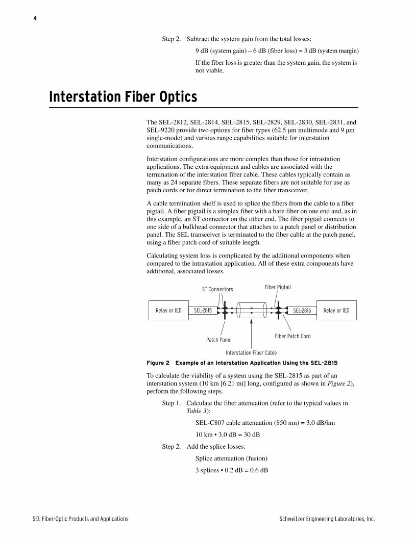
A cable termination shelf is used to splice the fibers from the cable to a fiber pigtail. A fiber pigtail is a simplex fiber with a bare fiber on one end and, as in this example, an ST connector on the other end. The fiber pigtail connects to one side of a bulkhead connector that attaches to a patch panel or distribution panel. The SEL transceiver is terminated to the fiber cable at the patch panel, using a fiber patch cord of suitable length.
Calculating system loss is complicated by the additional components when compared to the intrastation application. All of these extra components have additional, associated losses.
Figure 2 Example of an Interstation Application Using the SEL-2815
To calculate the viability of a system using the SEL-2815 as part of an interstation system (10 km [6.21 mi] long, configured as shown in Figure 2), perform the following steps.
Step 1. Calculate the fiber attenuation (refer to the typical values in Table 3):
SEL-C807 cable attenuation (850 nm) = 3.0 dB/km
10 km • 3.0 dB = 30 dB
Step 2. Add the splice losses:
Splice attenuation (fusion)
3 splices • 0.2 dB = 0.6 dB
SEL-2815Relay or IED
Patch Panel
ST Connectors Fiber Pigtail
Fiber Patch Cord
Interstation Fiber Cable
SEL-2815 Relay or IED
5
Schweitzer Engineering Laboratories, Inc. SEL Fiber-Optic Products and Applications
Step 3. Add the connector losses (connectors on the transceiver are included in the system gain):
Connector loss: 0.75 dB/connector
2 connectors • 0.75 dB = 1.5 dB
Step 4. Sum the losses:
30 dB (fiber) + 0.6 dB (splices) + 1.5 dB (connectors) = 32.1 dB (system loss)
Step 5. Subtract the system gain from the total losses:
41 dB (system gain) – 32.1 dB (system loss) = 8.9 dB (system margin), which is positive, so the system is viable.
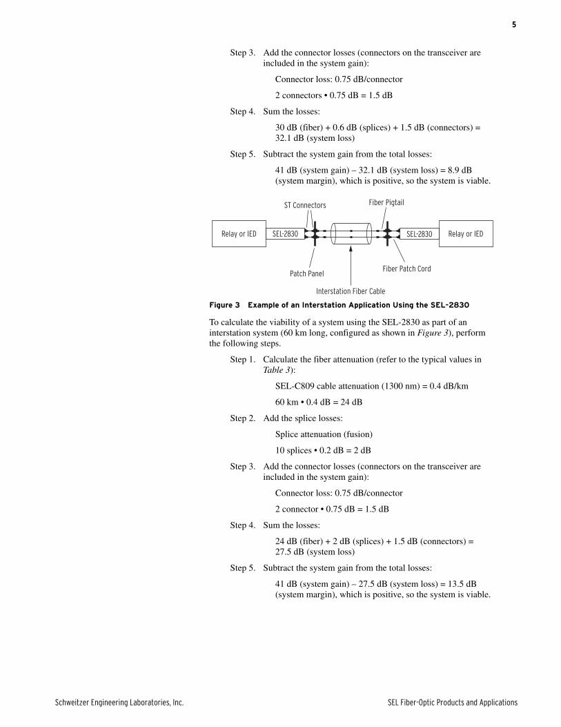
Figure 3 Example of an Interstation Application Using the SEL-2830
To calculate the viability of a system using the SEL-2830 as part of an interstation system (60 km long, configured as shown in Figure 3), perform the following steps.
Step 1. Calculate the fiber attenuation (refer to the typical values in Table 3):
SEL-C809 cable attenuation (1300 nm) = 0.4 dB/km
60 km • 0.4 dB = 24 dB
Step 2. Add the splice losses:
Splice attenuation (fusion)
10 splices • 0.2 dB = 2 dB
Step 3. Add the connector losses (connectors on the transceiver are included in the system gain):
Connector loss: 0.75 dB/connector
2 connector • 0.75 dB = 1.5 dB
Step 4. Sum the losses:
24 dB (fiber) + 2 dB (splices) + 1.5 dB (connectors) = 27.5 dB (system loss)
Step 5. Subtract the system gain from the total losses:
41 dB (system gain) – 27.5 dB (system loss) = 13.5 dB (system margin), which is positive, so the system is viable.
SEL-2830Relay or IED
Patch Panel
ST Connectors Fiber Pigtail
Fiber Patch Cord
Interstation Fiber Cable
SEL-2830 Relay or IED
6
SEL Fiber-Optic Products and Applications Schweitzer Engineering Laboratories, Inc.
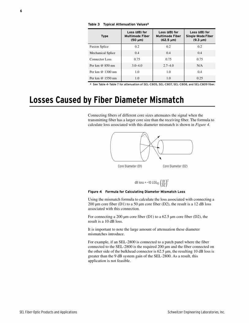
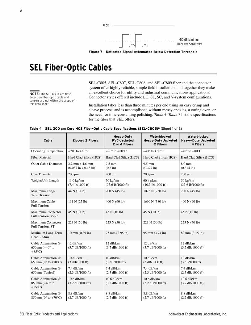
Losses Caused by Fiber Diameter Mismatch
Connecting fibers of different core sizes attenuates the signal when the transmitting fiber has a larger core size than the receiving fiber. The formula to calculate loss associated with this diameter mismatch is shown in Figure 4.
Figure 4 Formula for Calculating Diameter Mismatch Loss
Using the mismatch formula to calculate the loss associated with connecting a 200 µm core fiber (D1) to a 50 µm core fiber (D2), the result is a 12 dB loss associated with this connection.
For connecting a 200 µm core fiber (D1) to a 62.5 µm core fiber (D2), the result is a 10 dB loss.
It is important to note the large amount of attenuation these diameter mismatches introduce.
For example, if an SEL-2800 is connected to a patch panel where the fiber connected to the SEL-2800 is the required 200 µm and the fiber connected on the other side of the bulkhead connector is 62.5 µm, the resulting 10 dB loss is greater than the 9 dB system gain of the SEL-2800. As a result, this application is not feasible.
Table 3 Typical Attenuation Valuesa
a See Table 4–Table 7 for attenuation of SEL-C805, SEL-C807, SEL-C808, and SEL-C809 fiber.
TypeLoss (dB) for
Multimode Fiber (50 µm)
Loss (dB) for Multimode Fiber
(62.5 µm)
Loss (dB) for Single-Mode Fiber
(9.3 µm)
Fusion Splice 0.2 0.2 0.2
Mechanical Splice 0.4 0.4 0.4
Connector Loss 0.75 0.75 0.75
Per km @ 850 nm 3.0–4.0 2.7–4.0 N/A
Per km @ 1300 nm 1.0 1.0 0.4
Per km @ 1550 nm 1.0 1.0 0.25
Core Diameter (D1) Core Diameter (D2)
dB loss = —10 LOG10 ( (2D1D2
7
Schweitzer Engineering Laboratories, Inc. SEL Fiber-Optic Products and Applications
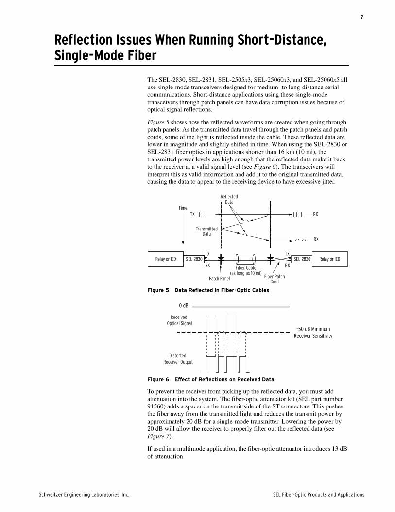
Reflection Issues When Running Short-Distance, Single-Mode Fiber
The SEL-2830, SEL-2831, SEL-2505x3, SEL-25060x3, and SEL-25060x5 all use single-mode transceivers designed for medium- to long-distance serial communications. Short-distance applications using these single-mode transceivers through patch panels can have data corruption issues because of optical signal reflections.
Figure 5 shows how the reflected waveforms are created when going through patch panels. As the transmitted data travel through the patch panels and patch cords, some of the light is reflected inside the cable. These reflected data are lower in magnitude and slightly shifted in time. When using the SEL-2830 or SEL-2831 fiber optics in applications shorter than 16 km (10 mi), the transmitted power levels are high enough that the reflected data make it back to the receiver at a valid signal level (see Figure 6). The transceivers will interpret this as valid information and add it to the original transmitted data, causing the data to appear to the receiving device to have excessive jitter.
Figure 5 Data Reflected in Fiber-Optic Cables
Figure 6 Effect of Reflections on Received Data
To prevent the receiver from picking up the reflected data, you must add attenuation into the system. The fiber-optic attenuator kit (SEL part number 91560) adds a spacer on the transmit side of the ST connectors. This pushes the fiber away from the transmitted light and reduces the transmit power by approximately 20 dB for a single-mode transmitter. Lowering the power by 20 dB will allow the receiver to properly filter out the reflected data (see Figure 7).
If used in a multimode application, the fiber-optic attenuator introduces 13 dB of attenuation.
Relay or IED Relay or IEDSEL-2830SEL-2830TX
RX
TX
RX
TX RX
RX
Time
Patch Panel
Reflected Data
Transmitted Data
Fiber Cable(as long as 10 mi)
Fiber Patch Cord
0 dB
–50 dB MinimumReceiver Sensitivity
Received Optical Signal
Distorted Receiver Output
8
SEL Fiber-Optic Products and Applications Schweitzer Engineering Laboratories, Inc.
Figure 7 Reflected Signal Attenuated Below Detection Threshold
SEL Fiber-Optic Cables
SEL-C805, SEL-C807, SEL-C808, and SEL-C809 fiber and the connector system offer highly reliable, simple field installation, and together they make an excellent choice for utility and industrial communications applications. Connector styles offered include LC, ST, SC, and V-system configurations.
Installation takes less than three minutes per end using an easy crimp and cleave process, and is accomplished without messy epoxies, a curing oven, or the need for time-consuming polishing. Table 4–Table 7 list the specifications for the fiber that SEL offers.
0 dB
–50 dB MinimumReceiver Sensitivity
NOTE: The SEL-C804 arc-flash detection fiber-optic cable and sensors are not within the scope of this data sheet.
Table 4 SEL 200 µm Core HCS Fiber-Optic Cable Specifications (SEL-C805)a (Sheet 1 of 2)
Cable Zipcord 2 FibersHeavy-Duty
PVC-Jacketed2 or 4 Fibers
Waterblocked Heavy-Duty Jacketed
2 Fibers
Waterblocked Heavy-Duty Jacketed
4 Fibers
Operating Temperature –20° to +80°C –20° to +80°C –40° to +80°C –40° to +80°C
Fiber Material Hard Clad Silica (HCS) Hard Clad Silica (HCS) Hard Clad Silica (HCS) Hard Clad Silica (HCS)
Outer Cable Diameter 2.2 mm x 4.6 mm(0.087 in x 0.18 in)
7.5 mm(0.3 in)
9.5 mm(0.374 in)
8.0 mm(0.314 in)
Core Diameter 200 µm 200 µm 200 µm 200 µm
Weight/Unit Length 11.0 kg/km (7.4 lb/1000 ft)
50 kg/km (33.6 lb/1000 ft)
60 kg/km(40.3 lb/1000 ft)
50 kg/km(33.6 lb/1000 ft)
Maximum Long-Term Tension
44 N (10 lb) 200 N (45 lb) 1023 N (230 lb) 200 N (45 lb)
Maximum Cable Pull Tension
111 N (25 lb) 400 N (90 lb) 1690 N (380 lb) 400 N (90 lb)
Maximum Connector Pull Tension, V-pin
45 N (10 lb) 45 N (10 lb) 45 N (10 lb) 45 N (10 lb)
Maximum Connector Pull Tension, ST
223 N (50 lb) 223 N (50 lb) 223 N (50 lb) 223 N (50 lb)
Minimum Long-Term Bend Radius
10 mm (0.39 in) 75 mm (2.95 in) 95 mm (3.74 in) 80 mm (3.15 in)
Cable Attenuation @ 650 nm (–40° to +85°C)
12 dB/km (3.7 dB/1000 ft)
12 dB/km (3.7 dB/1000 ft)
12 dB/km (3.7 dB/1000 ft)
12 dB/km (3.7 dB/1000 ft)
Cable Attenuation @ 650 nm (0° to +70°C)
10 dB/km (3 dB/1000 ft)
10 dB/km (3 dB/1000 ft)
10 dB/km (3 dB/1000 ft)
10 dB/km (3 dB/1000 ft)
Cable Attenuation @ 650 nm (Typical)
7.4 dB/km (2.3 dB/1000 ft)
7.4 dB/km (2.3 dB/1000 ft)
7.4 dB/km (2.3 dB/1000 ft)
7.4 dB/km (2.3 dB/1000 ft)
Cable Attenuation @ 850 nm (–40° to +85°C)
10.6 dB/km (3.2 dB/1000 ft)
10.6 dB/km (3.2 dB/1000 ft)
10.6 dB/km (3.2 dB/1000 ft)
10.6 dB/km (3.2 dB/1000 ft)
Cable Attenuation @ 850 nm (0° to +70°C)
8.8 dB/km (2.7 dB/1000 ft)
8.8 dB/km (2.7 dB/1000 ft)
8.8 dB/km (2.7 dB/1000 ft)
8.8 dB/km (2.7 dB/1000 ft)
9
Schweitzer Engineering Laboratories, Inc. SEL Fiber-Optic Products and Applications
Cable Attenuation @ 850 nm (Typical)
6.5 dB/km (2 dB/1000 ft)
6.5 dB/km (2 dB/1000 ft)
6.5 dB/km (2 dB/1000 ft)
6.5 dB/km (2 dB/1000 ft)
UL Rating Riser Rated (OFNR) Riser Rated (OFNR)
a SEL-C805 finished cable and field-terminated connector options are V-pin to V-pin and ST to ST.
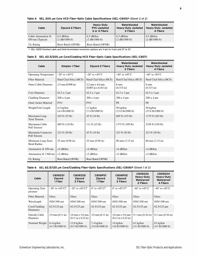
Table 4 SEL 200 µm Core HCS Fiber-Optic Cable Specifications (SEL-C805)a (Sheet 2 of 2)
Cable Zipcord 2 FibersHeavy-Duty
PVC-Jacketed2 or 4 Fibers
Waterblocked Heavy-Duty Jacketed
2 Fibers
Waterblocked Heavy-Duty Jacketed
4 Fibers
Table 5 SEL 62.5/200 µm Core/Cladding HCS Fiber-Optic Cable Specifications (SEL-C807)
Cable Simplex 1 Fiber Zipcord 2 FibersWaterblocked
Heavy-Duty Jacketed 2 Fibers
Waterblocked Heavy-Duty Jacketed
4 Fibers
Operating Temperature –20° to +85°C –20° to +85°C –40° to +85°C –40° to +85°C
Fiber Material Hard Clad Silica (HCS) Hard Clad Silica (HCS) Hard Clad Silica (HCS) Hard Clad Silica (HCS)
Outer Cable Diameter 2.5 mm (0.098 in) 2.2 mm x 4.6 mm (0.087 in x 0.181 in)
8 mm(0.315 in)
8 mm(0.315 in)
Core Diameter 62.5 ± 3 µm 62.5 ± 3 µm 62.5 ± 3 µm 62.5 ± 3 µm
Cladding Diameter 200 ± 4 µm 200 ± 4 µm 200 ± 4 µm 200 ± 4 µm
Outer Jacket Material PVC PVC PE PE
Weight/Unit Length 6.5 kg/km (4.4 lb/1000 ft)
11 kg/km (7.4 lb/1000 ft)
50 kg/km (33.6 lb/1000 ft)
50 kg/km (33.6 lb/1000 ft)
Maximum Long-Term Tension
245 N (55 lb) 45 N (10 lb) 689 N (155 lb) 1179 N (265 lb)
Maximum Cable Pull Tension
489 N (110 lb) 111 N (25 lb) 1375 N (309 lb) 2358 N (530 lb)
Maximum Connector Pull Tension
223 N (50 lb) 45 N (10 lb) 223 N (50 lb) 223 N (50 lb)
Minimum Long-Term Bend Radius
25 mm (0.98 in) 25 mm (0.98 in) 80 mm (3.15 in) 80 mm (3.15 in)
Attenuation @ 850 nm <4 dB/km <4 dB/km <4 dB/km <4 dB/km
Attenuation @ 1300 nm <2 dB/km <2 dB/km <2 dB/km <2 dB/km
UL Rating Riser Rated (OFNR) Riser Rated (OFNR)
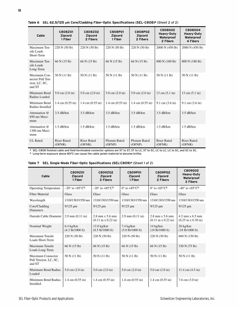
Table 6 SEL 62.5/125 µm Core/Cladding Fiber-Optic Specifications (SEL-C808)a (Sheet 1 of 2)
CableC808Z01Zipcord1 Fiber
C808Z02Zipcord2 Fibers
C808P01Zipcord1 Fiber
C808P02Zipcord2 Fibers
C808G02Heavy-Duty Waterproof
2 Fibers
C808G04Heavy-Duty Waterproof
4 Fibers
Operating Tem-perature
–20° to +85°Cb –20° to +85°Cb 0° to +85°Cb 0° to +85°Cb –40° to +85°C –40° to +85°C
Fiber Material Glass Glass Glass Glass Glass Glass
Wavelength 850/1300 nm 850/1300 nm 850/1300 nm 850/1300 nm 850/1300 nm 850/1300 nm
Core/Cladding Diameters
62.5/125 µm 62.5/125 µm 62.5/125 µm 62.5/125 µm 62.5/125 µm 62.5/125 µm
Outside Cable Diameter
2.9 mm (0.11 in) 2.8 mm x 5.6 mm(0.11 in x 0.22 in)
2.9 mm (0.11 in) 2.8 mm x 5.6 mm(0.11 in x 0.22 in)
9.1 mm (0.36 in) 9.1 mm (0.36 in)
Nominal Weight 6.4 kg/km (4.3 lb/1000 ft)
12.8 kg/km (8.5 lb/1000 ft)
7.4 kg/km (5.0 lb/1000 ft)
14 kg/km (10 lb/1000 ft)
61 kg/km(41 lb/1000 ft)
61 kg/km(41 lb/1000 ft)
10
SEL Fiber-Optic Products and Applications Schweitzer Engineering Laboratories, Inc.
Maximum Ten-sile Loads Short-Term
220 N (50 lb) 220 N (50 lb) 220 N (50 lb) 220 N (50 lb) 2000 N (450 lb) 2000 N (450 lb)
Maximum Ten-sile Loads Long-Term
66 N (15 lb) 66 N (15 lb) 66 N (15 lb) 66 N (15 lb) 800 N (180 lb) 800 N (180 lb)
Maximum Con-nector Pull Ten-sion, LC, SC, and ST
50 N (11 lb) 50 N (11 lb) 50 N (11 lb) 50 N (11 lb) 50 N (11 lb) 50 N (11 lb)
Minimum Bend Radius Loaded
5.0 cm (2.0 in) 5.0 cm (2.0 in) 5.0 cm (2.0 in) 5.0 cm (2.0 in) 13 cm (5.1 in) 13 cm (5.1 in)
Minimum Bend Radius Installed
1.4 cm (0.55 in) 1.4 cm (0.55 in) 1.4 cm (0.55 in) 1.4 cm (0.55 in) 9.1 cm (3.6 in) 9.1 cm (3.6 in)
Attenuation @ 850 nm Maxi-mum
3.5 dB/km 3.5 dB/km 3.5 dB/km 3.5 dB/km 3.5 dB/km 3.5 dB/km
Attenuation @ 1300 nm Maxi-mum
1.5 dB/km 1.5 dB/km 1.5 dB/km 1.5 dB/km 1.5 dB/km 1.5 dB/km
UL Rated Riser Rated (OFNR)
Riser Rated (OFNR)
Plenum Rated (OFNP)
Plenum Rated (OFNP)
Riser Rated (OFNR)
Riser Rated (OFNR)
a SEL-C808 finished cable and field-terminated connector options are ST to ST, ST to LC, ST to SC, LC to LC, LC to SC, and SC to SC.b Long-term exposure above 80°C can cause the cable jacket material to become brittle.
Table 7 SEL Single-Mode Fiber-Optic Specifications (SEL-C809)a (Sheet 1 of 2)
CableC809Z01Zipcord1 Fiber
C809Z02Zipcord2 Fibers
C809P01Zipcord1 Fiber
C809P02Zipcord2 Fibers
C809G02Heavy-Duty Waterproof
2 Fibers
Operating Temperature –20° to +85°Cb –20° to +85°Cb 0° to +85°Cb 0° to +85°Cb –40° to +85°Cb
Fiber Material Glass Glass Glass Glass Glass
Wavelength 1310/1383/1550 nm 1310/1383/1550 nm 1310/1383/1550 nm 1310/1383/1550 nm 1310/1383/1550 nm
Core/Cladding Diameters
9/125 µm 9/125 µm 9/125 µm 9/125 µm 9/125 µm
Outside Cable Diameter 2.9 mm (0.11 in) 2.8 mm x 5.6 mm(0.11 in x 0.22 in)
2.9 mm (0.11 in) 2.8 mm x 5.6 mm(0.11 in x 0.22 in)
4.2 mm x 6.5 mm(0.25 in x 0.30 in)
Nominal Weight 6.4 kg/km (4.3 lb/1000 ft)
12.8 kg/km (8.5 lb/1000 ft)
7.4 kg/km (5.0 lb/1000 ft)
14 kg/km (10 lb/1000 ft)
26 kg/km (18 lb/1000 ft)
Maximum Tensile Loads Short-Term
220 N (50 lb) 220 N (50 lb) 220 N (50 lb) 220 N (50 lb) 660 N (150 lb)
Maximum Tensile Loads Long-Term
66 N (15 lb) 66 N (15 lb) 66 N (15 lb) 66 N (15 lb) 330 N (75 lb)
Maximum Connector Pull Tension, LC, SC, and ST
50 N (11 lb) 50 N (11 lb) 50 N (11 lb) 50 N (11 lb) 50 N (11 lb)
Minimum Bend Radius Loaded
5.0 cm (2.0 in) 5.0 cm (2.0 in) 5.0 cm (2.0 in) 5.0 cm (2.0 in) 11.4 cm (4.5 in)
Minimum Bend Radius Installed
1.4 cm (0.55 in) 1.4 cm (0.55 in) 1.4 cm (0.55 in) 1.4 cm (0.55 in) 7.6 cm (3.0 in)
Table 6 SEL 62.5/125 µm Core/Cladding Fiber-Optic Specifications (SEL-C808)a (Sheet 2 of 2)
CableC808Z01Zipcord1 Fiber
C808Z02Zipcord2 Fibers
C808P01Zipcord1 Fiber
C808P02Zipcord2 Fibers
C808G02Heavy-Duty Waterproof
2 Fibers
C808G04Heavy-Duty Waterproof
4 Fibers
11
Schweitzer Engineering Laboratories, Inc. SEL Fiber-Optic Products and Applications
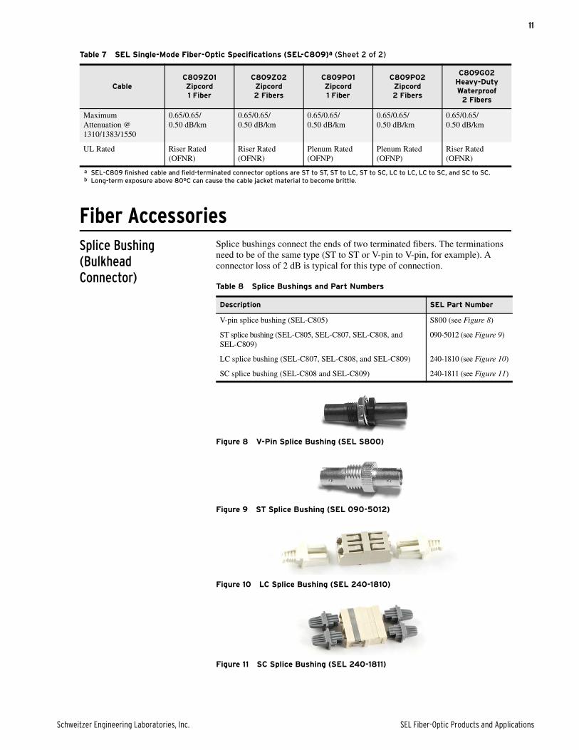
Fiber AccessoriesSplice Bushing(BulkheadConnector)
Splice bushings connect the ends of two terminated fibers. The terminations need to be of the same type (ST to ST or V-pin to V-pin, for example). A connector loss of 2 dB is typical for this type of connection.
Figure 8 V-Pin Splice Bushing (SEL S800)
Figure 9 ST Splice Bushing (SEL 090-5012)
Figure 10 LC Splice Bushing (SEL 240-1810)
Figure 11 SC Splice Bushing (SEL 240-1811)
Maximum Attenuation @ 1310/1383/1550
0.65/0.65/0.50 dB/km
0.65/0.65/0.50 dB/km
0.65/0.65/0.50 dB/km
0.65/0.65/0.50 dB/km
0.65/0.65/0.50 dB/km
UL Rated Riser Rated (OFNR)
Riser Rated (OFNR)
Plenum Rated (OFNP)
Plenum Rated (OFNP)
Riser Rated (OFNR)
a SEL-C809 finished cable and field-terminated connector options are ST to ST, ST to LC, ST to SC, LC to LC, LC to SC, and SC to SC.b Long-term exposure above 80°C can cause the cable jacket material to become brittle.
Table 7 SEL Single-Mode Fiber-Optic Specifications (SEL-C809)a (Sheet 2 of 2)
CableC809Z01Zipcord1 Fiber
C809Z02Zipcord2 Fibers
C809P01Zipcord1 Fiber
C809P02Zipcord2 Fibers
C809G02Heavy-Duty Waterproof
2 Fibers
Table 8 Splice Bushings and Part Numbers
Description SEL Part Number
V-pin splice bushing (SEL-C805) S800 (see Figure 8)
ST splice bushing (SEL-C805, SEL-C807, SEL-C808, and SEL-C809)
090-5012 (see Figure 9)
LC splice bushing (SEL-C807, SEL-C808, and SEL-C809) 240-1810 (see Figure 10)
SC splice bushing (SEL-C808 and SEL-C809) 240-1811 (see Figure 11)
12
SEL Fiber-Optic Products and Applications Schweitzer Engineering Laboratories, Inc.
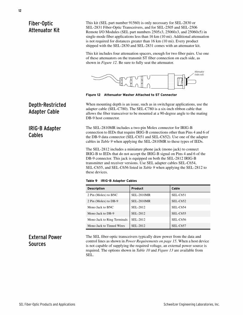
Fiber-Optic Attenuator Kit
This kit (SEL part number 91560) is only necessary for SEL-2830 or SEL-2831 Fiber-Optic Transceivers, and for SEL-2505 and SEL-2506 Remote I/O Modules (SEL part numbers 2505x3, 25060x3, and 25060x5) in single-mode fiber applications less than 16 km (10 mi). Additional attenuation is not required for distances greater than 16 km (10 mi). Every product shipped with the SEL-2830 and SEL-2831 comes with an attenuator kit.
This kit includes four attenuation spacers, enough for two fiber pairs. Use one of these attenuators on the transmit ST fiber connection on each side, as shown in Figure 12. Be sure to fully seat the attenuator.
Figure 12 Attenuator Washer Attached to ST Connector
Depth-Restricted Adapter Cable
When mounting depth is an issue, such as in switchgear applications, use the adapter cable (SEL-C780). The SEL-C780 is a six-inch ribbon cable that allows the fiber transceiver to be mounted at a 90-degree angle to the mating DB-9 host connector.
IRIG-B Adapter Cables
The SEL-2810MR includes a two-pin Molex connector for IRIG-B connection to IEDs that require IRIG-B connections other than Pins 4 and 6 of the DB-9 data connector (SEL-C651 and SEL-C652). Use one of the adapter cables in Table 9 when applying the SEL-2810MR to these types of IEDs.
The SEL-2812 includes a miniature phone jack (mono jack) to connect IRIG-B to IEDs that do not accept the IRIG-B signal on Pins 4 and 6 of the DB-9 connector. This jack is equipped on both the SEL-2812 IRIG-B transmitter and receiver versions. Use SEL adapter cables SEL-C654, SEL-C655, and SEL-C656 listed in Table 9 when applying the SEL-2812 to these devices.
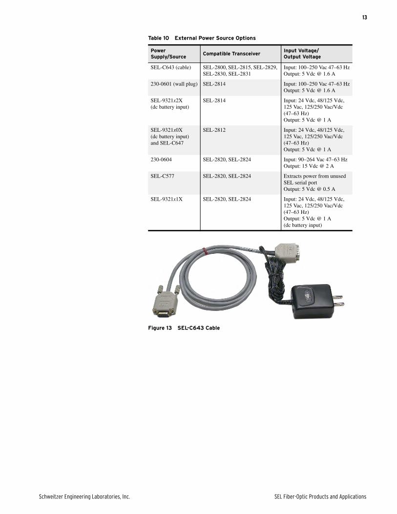
External Power Sources
The SEL fiber-optic transceivers typically draw power from the data and control lines as shown in Power Requirements on page 15. When a host device is not capable of supplying the required voltage, an external power source is required. The options shown in Table 10 and Figure 13 are available from SEL.
Attenuator(nubs out)
Table 9 IRIG-B Adapter Cables
Description Product Cable
2 Pin (Molex) to BNC SEL-2810MR SEL-C651
2 Pin (Molex) to DB-9 SEL-2810MR SEL-C652
Mono Jack to BNC SEL-2812 SEL-C654
Mono Jack to DB-9 SEL-2812 SEL-C655
Mono Jack to Ring Terminals SEL-2812 SEL-C656
Mono Jack to Tinned Wires SEL-2812 SEL-C657
13
Schweitzer Engineering Laboratories, Inc. SEL Fiber-Optic Products and Applications
Figure 13 SEL-C643 Cable
Table 10 External Power Source Options
Power Supply/Source
Compatible TransceiverInput Voltage/Output Voltage
SEL-C643 (cable) SEL-2800, SEL-2815, SEL-2829, SEL-2830, SEL-2831
Input: 100–250 Vac 47–63 HzOutput: 5 Vdc @ 1.6 A
230-0601 (wall plug) SEL-2814 Input: 100–250 Vac 47–63 HzOutput: 5 Vdc @ 1.6 A
SEL-9321x2X (dc battery input)
SEL-2814 Input: 24 Vdc, 48/125 Vdc, 125 Vac, 125/250 Vac/Vdc (47–63 Hz)Output: 5 Vdc @ 1 A
SEL-9321x0X (dc battery input) and SEL-C647
SEL-2812 Input: 24 Vdc, 48/125 Vdc, 125 Vac, 125/250 Vac/Vdc (47–63 Hz)Output: 5 Vdc @ 1 A
230-0604 SEL-2820, SEL-2824 Input: 90–264 Vac 47–63 HzOutput: 15 Vdc @ 2 A
SEL-C577 SEL-2820, SEL-2824 Extracts power from unused SEL serial portOutput: 5 Vdc @ 0.5 A
SEL-9321x1X SEL-2820, SEL-2824 Input: 24 Vdc, 48/125 Vdc, 125 Vac, 125/250 Vac/Vdc (47–63 Hz)Output: 5 Vdc @ 1 A(dc battery input)
14
SEL Fiber-Optic Products and Applications Schweitzer Engineering Laboratories, Inc.
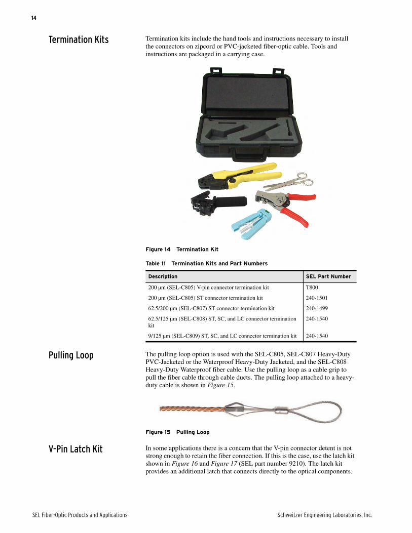
Termination Kits Termination kits include the hand tools and instructions necessary to install the connectors on zipcord or PVC-jacketed fiber-optic cable. Tools and instructions are packaged in a carrying case.
Figure 14 Termination Kit
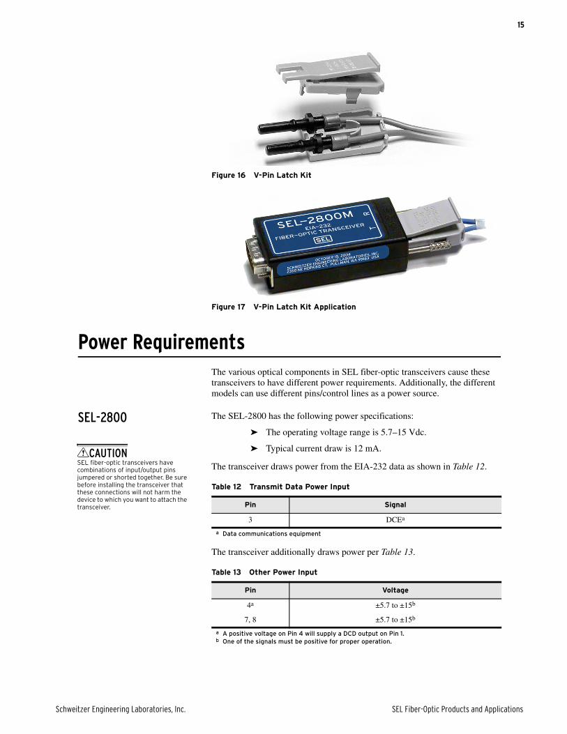
Pulling Loop The pulling loop option is used with the SEL-C805, SEL-C807 Heavy-Duty PVC-Jacketed or the Waterproof Heavy-Duty Jacketed, and the SEL-C808 Heavy-Duty Waterproof fiber cable. Use the pulling loop as a cable grip to pull the fiber cable through cable ducts. The pulling loop attached to a heavy-duty cable is shown in Figure 15.
Figure 15 Pulling Loop
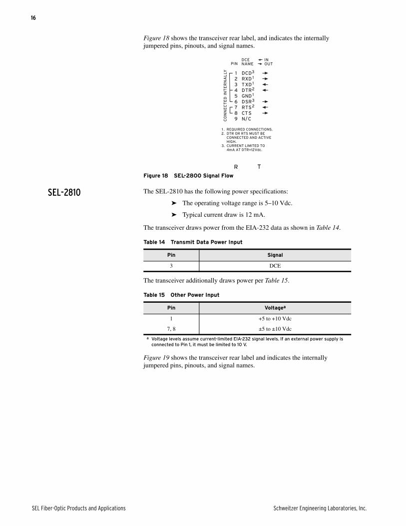
V-Pin Latch Kit In some applications there is a concern that the V-pin connector detent is not strong enough to retain the fiber connection. If this is the case, use the latch kit shown in Figure 16 and Figure 17 (SEL part number 9210). The latch kit provides an additional latch that connects directly to the optical components.
Table 11 Termination Kits and Part Numbers
Description SEL Part Number
200 µm (SEL-C805) V-pin connector termination kit T800
200 µm (SEL-C805) ST connector termination kit 240-1501
62.5/200 µm (SEL-C807) ST connector termination kit 240-1499
62.5/125 µm (SEL-C808) ST, SC, and LC connector termination kit
240-1540
9/125 µm (SEL-C809) ST, SC, and LC connector termination kit 240-1540
15
Schweitzer Engineering Laboratories, Inc. SEL Fiber-Optic Products and Applications
Figure 16 V-Pin Latch Kit
Figure 17 V-Pin Latch Kit Application
Power RequirementsThe various optical components in SEL fiber-optic transceivers cause these transceivers to have different power requirements. Additionally, the different models can use different pins/control lines as a power source.
SEL-2800 The SEL-2800 has the following power specifications:
➤ The operating voltage range is 5.7–15 Vdc.
➤ Typical current draw is 12 mA.
The transceiver draws power from the EIA-232 data as shown in Table 12.
The transceiver additionally draws power per Table 13.
Table 12 Transmit Data Power Input
Pin Signal
3 DCEa
a Data communications equipment
Table 13 Other Power Input
Pin Voltage
4a
a A positive voltage on Pin 4 will supply a DCD output on Pin 1.
±5.7 to ±15b
b One of the signals must be positive for proper operation.
7, 8 ±5.7 to ±15b
CAUTIONSEL fiber-optic transceivers have combinations of input/output pins jumpered or shorted together. Be sure before installing the transceiver that these connections will not harm the device to which you want to attach the transceiver.
16
SEL Fiber-Optic Products and Applications Schweitzer Engineering Laboratories, Inc.
Figure 18 shows the transceiver rear label, and indicates the internally jumpered pins, pinouts, and signal names.
Figure 18 SEL-2800 Signal Flow
SEL-2810 The SEL-2810 has the following power specifications:
➤ The operating voltage range is 5–10 Vdc.
➤ Typical current draw is 12 mA.
The transceiver draws power from the EIA-232 data as shown in Table 14.
The transceiver additionally draws power per Table 15.
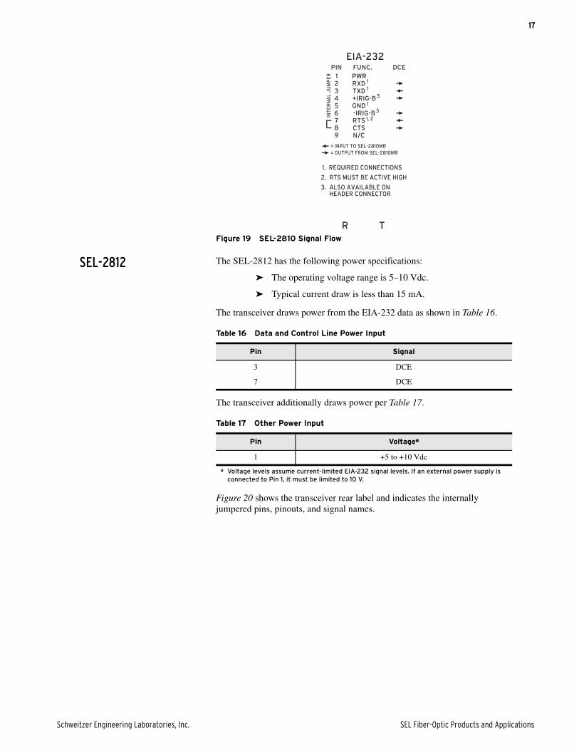
Figure 19 shows the transceiver rear label and indicates the internally jumpered pins, pinouts, and signal names.
Table 14 Transmit Data Power Input
Pin Signal
3 DCE
Table 15 Other Power Input
Pin Voltagea
a Voltage levels assume current-limited EIA-232 signal levels. If an external power supply is connected to Pin 1, it must be limited to 10 V.
1 +5 to +10 Vdc
7, 8 ±5 to ±10 Vdc
17
Schweitzer Engineering Laboratories, Inc. SEL Fiber-Optic Products and Applications
Figure 19 SEL-2810 Signal Flow
SEL-2812 The SEL-2812 has the following power specifications:
➤ The operating voltage range is 5–10 Vdc.
➤ Typical current draw is less than 15 mA.
The transceiver draws power from the EIA-232 data as shown in Table 16.
The transceiver additionally draws power per Table 17.
Figure 20 shows the transceiver rear label and indicates the internally jumpered pins, pinouts, and signal names.
PWR
Table 16 Data and Control Line Power Input
Pin Signal
3 DCE
7 DCE
Table 17 Other Power Input
Pin Voltagea
a Voltage levels assume current-limited EIA-232 signal levels. If an external power supply is connected to Pin 1, it must be limited to 10 V.
1 +5 to +10 Vdc
18
SEL Fiber-Optic Products and Applications Schweitzer Engineering Laboratories, Inc.
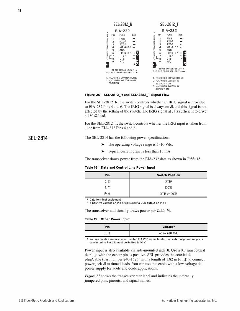
Figure 20 SEL-2812_R and SEL-2812_T Signal Flow
For the SEL-2812_R, the switch controls whether an IRIG signal is provided to EIA-232 Pins 4 and 6. The IRIG signal is always on J1, and this signal is not affected by the setting of the switch. The IRIG signal at J1 is sufficient to drive a 480 Ω load.
For the SEL-2812_T, the switch controls whether the IRIG input is taken from J1 or from EIA-232 Pins 4 and 6.
SEL-2814 The SEL-2814 has the following power specifications:
➤ The operating voltage range is 5–10 Vdc.
➤ Typical current draw is less than 15 mA.
The transceiver draws power from the EIA-232 data as shown in Table 18.
The transceiver additionally draws power per Table 19.
Power input is also available via side-mounted jack J1. Use a 0.7 mm coaxial dc plug, with the center pin as positive. SEL provides the coaxial dc plug/cable (part number 240-1525, with a length of 1.82 m [6 ft]) to connect power jack J1 to tinned leads. You can use this cable with a low-voltage dc power supply for ac/dc and dc/dc applications.
Figure 21 shows the transceiver rear label and indicates the internally jumpered pins, pinouts, and signal names.
CO
NN
EC
TE
D I
NT
ER
NA
LL
YC
ON
NE
CT
ED
IN
TE
RN
AL
LY EIA–232EIA–232
1. REQUIRED CONNECTIONS.2. N/C WHEN SWITCH IN 232 POSITION.3. N/C WHEN SWITCH IN J1 POSITION.
1. REQUIRED CONNECTIONS.2. N/C WHEN SWITCH IN 232 POSITION.3. N/C WHEN SWITCH IN J1 POSITION.
OUTPUT FROM SEL–2812 = OUTPUT FROM SEL–2812 =INPUT TO SEL–2812 =INPUT TO SEL–2812 =
DCEDCEFUNC.FUNC.PINPIN
44 +IRIG—B 3+IRIG—B 3
GNDGND
CTSCTSRTS 1RTS 1—IRIG—B 3—IRIG—B 3
55
887766
TXD 1TXD 1RXD 1RXD 1PWRPWR
332211
99 N/CN/C22
23
22
32
J1
J1J
1J
1
SEL-2812_R SEL-2812_T
CO
NN
EC
TE
D I
NT
ER
NA
LL
YC
ON
NE
CT
ED
IN
TE
RN
AL
LY
1. REQUIRED CONNECTIONS.2. N/C WHEN SWITCH IN OFF POSITION.
1. REQUIRED CONNECTIONS.2. N/C WHEN SWITCH IN OFF POSITION.
OUTPUT FROM SEL–2812 =OUTPUT FROM SEL–2812 =INPUT TO SEL–2812 =INPUT TO SEL–2812 =
DCEDCEFUNC.FUNC.PINPIN
44 +IRIG—B 2+IRIG—B 2
GNDGND
CTSCTSRTS 1RTS 1—IRIG—B 2—IRIG—B 2
55
887766
TXD 1TXD 1RXD 1RXD 1PWRPWR
332211
99 N/CN/C
EIA–232EIA–232
J1
J1
ON
ON
OF
FO
FF
22
Table 18 Data and Control Line Power Input
Pin Switch Position
2, 8 DTEa
a Data terminal equipment
3, 7 DCE
4b, 6
b A positive voltage on Pin 4 will supply a DCD output on Pin 1.
DTE or DCE
Table 19 Other Power Input
Pin Voltagea
a Voltage levels assume current-limited EIA-232 signal levels. If an external power supply is connected to Pin 1, it must be limited to 10 V.
1, J1 +5 to +10 Vdc
19
Schweitzer Engineering Laboratories, Inc. SEL Fiber-Optic Products and Applications
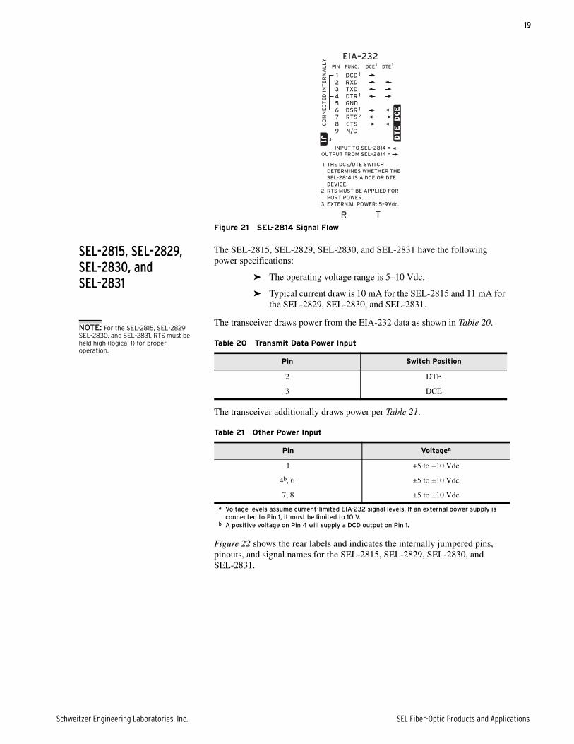
Figure 21 SEL-2814 Signal Flow
SEL-2815, SEL-2829, SEL-2830, and SEL-2831
The SEL-2815, SEL-2829, SEL-2830, and SEL-2831 have the following power specifications:
➤ The operating voltage range is 5–10 Vdc.
➤ Typical current draw is 10 mA for the SEL-2815 and 11 mA for the SEL-2829, SEL-2830, and SEL-2831.
The transceiver draws power from the EIA-232 data as shown in Table 20.
The transceiver additionally draws power per Table 21.
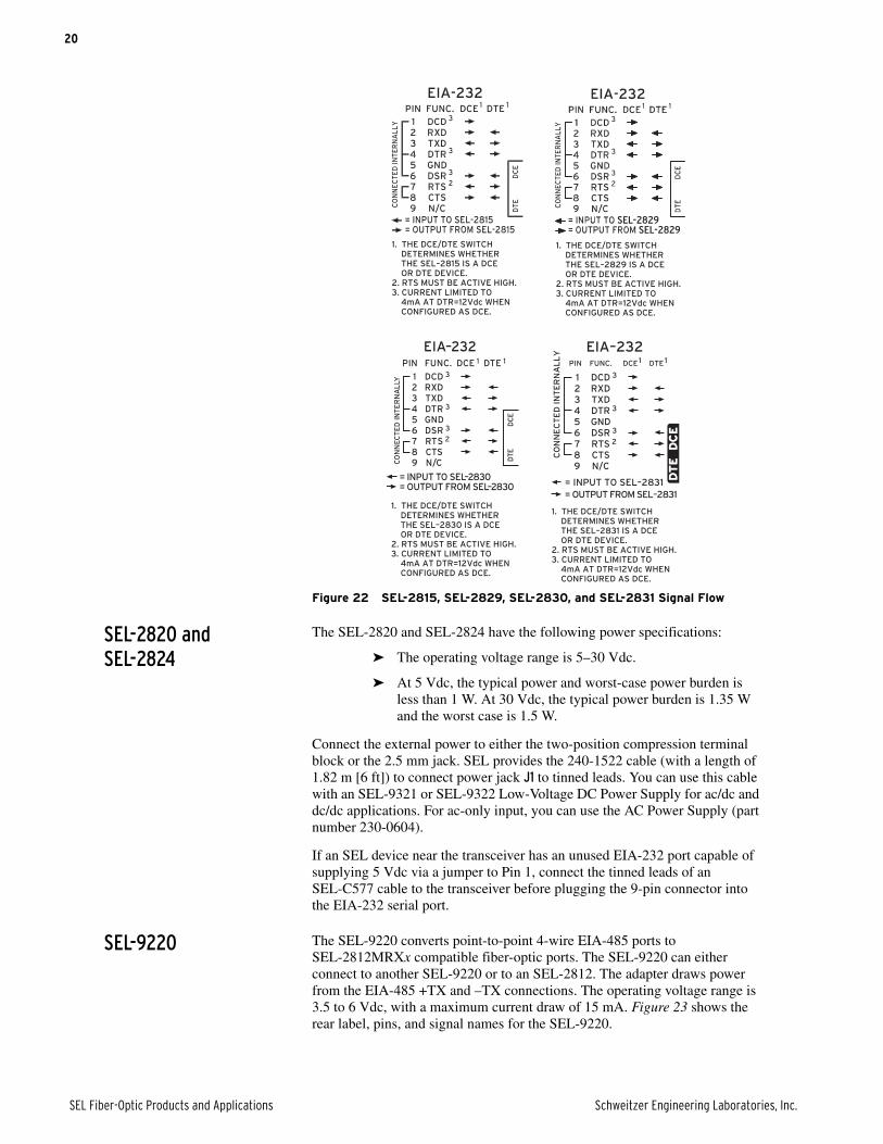
Figure 22 shows the rear labels and indicates the internally jumpered pins, pinouts, and signal names for the SEL-2815, SEL-2829, SEL-2830, and SEL-2831.
Table 20 Transmit Data Power Input
Pin Switch Position
2 DTE
3 DCE
Table 21 Other Power Input
Pin Voltagea
a Voltage levels assume current-limited EIA-232 signal levels. If an external power supply is connected to Pin 1, it must be limited to 10 V.
1 +5 to +10 Vdc
4b, 6
b A positive voltage on Pin 4 will supply a DCD output on Pin 1.
±5 to ±10 Vdc
7, 8 ±5 to ±10 Vdc
NOTE: For the SEL-2815, SEL-2829, SEL-2830, and SEL-2831, RTS must be held high (logical 1) for proper operation.
20
SEL Fiber-Optic Products and Applications Schweitzer Engineering Laboratories, Inc.
Figure 22 SEL-2815, SEL-2829, SEL-2830, and SEL-2831 Signal Flow
SEL-2820 and SEL-2824
The SEL-2820 and SEL-2824 have the following power specifications:
➤ The operating voltage range is 5–30 Vdc.
➤ At 5 Vdc, the typical power and worst-case power burden is less than 1 W. At 30 Vdc, the typical power burden is 1.35 W and the worst case is 1.5 W.
Connect the external power to either the two-position compression terminal block or the 2.5 mm jack. SEL provides the 240-1522 cable (with a length of 1.82 m [6 ft]) to connect power jack J1 to tinned leads. You can use this cable with an SEL-9321 or SEL-9322 Low-Voltage DC Power Supply for ac/dc and dc/dc applications. For ac-only input, you can use the AC Power Supply (part number 230-0604).
If an SEL device near the transceiver has an unused EIA-232 port capable of supplying 5 Vdc via a jumper to Pin 1, connect the tinned leads of an SEL-C577 cable to the transceiver before plugging the 9-pin connector into the EIA-232 serial port.
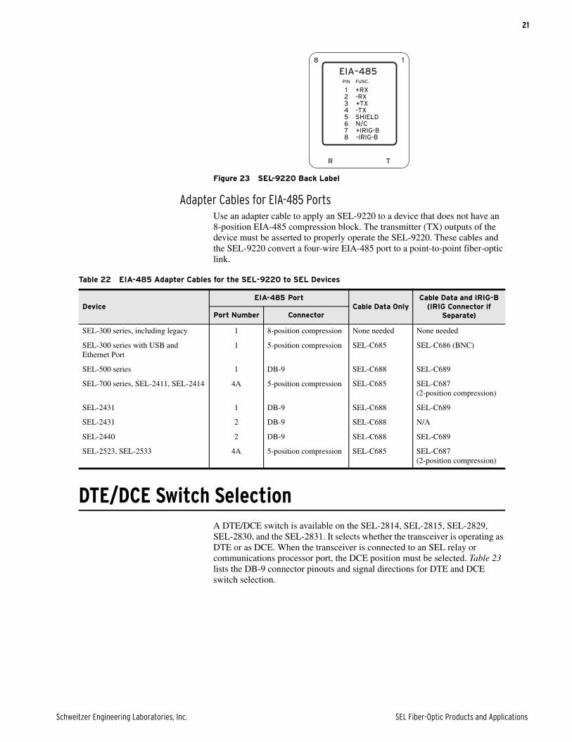
SEL-9220 The SEL-9220 converts point-to-point 4-wire EIA-485 ports to SEL-2812MRXx compatible fiber-optic ports. The SEL-9220 can either connect to another SEL-9220 or to an SEL-2812. The adapter draws power from the EIA-485 +TX and –TX connections. The operating voltage range is 3.5 to 6 Vdc, with a maximum current draw of 15 mA. Figure 23 shows the rear label, pins, and signal names for the SEL-9220.
1. THE DCE/DTE SWITCH DETERMINES WHETHER THE SEL–2831 IS A DCE OR DTE DEVICE.2. RTS MUST BE ACTIVE HIGH.3. CURRENT LIMITED TO 4mA AT DTR=12Vdc WHEN CONFIGURED AS DCE.
1. THE DCE/DTE SWITCH DETERMINES WHETHER THE SEL–2831 IS A DCE OR DTE DEVICE.2. RTS MUST BE ACTIVE HIGH.3. CURRENT LIMITED TO 4mA AT DTR=12Vdc WHEN CONFIGURED AS DCE.
DCE1DCE1FUNC.FUNC.PINPIN
CO
NN
EC
TE
D I
NT
ER
NA
LL
YC
ON
NE
CT
ED
IN
TE
RN
AL
LY
44 DTR 3DTR 3
GNDGND
CTSCTSRTS 2RTS 2DSR 3DSR 3
55
887766
TXDTXDRXDRXDDCD 3DCD 3
332211
DTE1DTE1
99 N/CN/C
= OUTPUT FROM SEL–2831= OUTPUT FROM SEL–2831= INPUT TO SEL–2831= INPUT TO SEL–2831
EIA–232EIA–232
DC
ED
CE
DT
ED
TE
1. THE DCE/DTE SWITCH DETERMINES WHETHER THE SEL–2815 IS A DCE OR DTE DEVICE.2. RTS MUST BE ACTIVE HIGH.3. CURRENT LIMITED TO 4mA AT DTR=12Vdc WHEN CONFIGURED AS DCE.
1. THE DCE/DTE SWITCH DETERMINES WHETHER THE SEL–2829 IS A DCE OR DTE DEVICE.2. RTS MUST BE ACTIVE HIGH.3. CURRENT LIMITED TO 4mA AT DTR=12Vdc WHEN CONFIGURED AS DCE.
1. THE DCE/DTE SWITCH DETERMINES WHETHER THE SEL–2830 IS A DCE OR DTE DEVICE.2. RTS MUST BE ACTIVE HIGH.3. CURRENT LIMITED TO 4mA AT DTR=12Vdc WHEN CONFIGURED AS DCE.
1. THE DCE/DTE SWITCH DETERMINES WHETHER THE SEL–2830 IS A DCE OR DTE DEVICE.2. RTS MUST BE ACTIVE HIGH.3. CURRENT LIMITED TO 4mA AT DTR=12Vdc WHEN CONFIGURED AS DCE.
21
Schweitzer Engineering Laboratories, Inc. SEL Fiber-Optic Products and Applications
Figure 23 SEL-9220 Back Label
Adapter Cables for EIA-485 PortsUse an adapter cable to apply an SEL-9220 to a device that does not have an 8-position EIA-485 compression block. The transmitter (TX) outputs of the device must be asserted to properly operate the SEL-9220. These cables and the SEL-9220 convert a four-wire EIA-485 port to a point-to-point fiber-optic link.
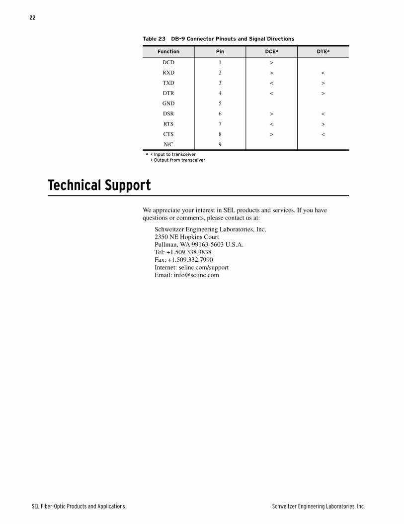
DTE/DCE Switch SelectionA DTE/DCE switch is available on the SEL-2814, SEL-2815, SEL-2829, SEL-2830, and the SEL-2831. It selects whether the transceiver is operating as DTE or as DCE. When the transceiver is connected to an SEL relay or communications processor port, the DCE position must be selected. Table 23 lists the DB-9 connector pinouts and signal directions for DTE and DCE switch selection.
RR TT
1188
EIA–485EIA–485FUNC.FUNC.PINPIN
44 -TX-TXSHIELDSHIELD
-IRIG-B-IRIG-B+IRIG-B+IRIG-BN/CN/C
55
887766
+TX+TX-RX-RX+RX+RX
332211
Table 22 EIA-485 Adapter Cables for the SEL-9220 to SEL Devices
DeviceEIA-485 Port
Cable Data OnlyCable Data and IRIG-B
(IRIG Connector if Separate)Port Number Connector
SEL-300 series, including legacy 1 8-position compression None needed None needed
SEL-300 series with USB and Ethernet Port
1 5-position compression SEL-C685 SEL-C686 (BNC)
SEL-500 series 1 DB-9 SEL-C688 SEL-C689
SEL-700 series, SEL-2411, SEL-2414 4A 5-position compression SEL-C685 SEL-C687 (2-position compression)
SEL-2431 1 DB-9 SEL-C688 SEL-C689
SEL-2431 2 DB-9 SEL-C688 N/A
SEL-2440 2 DB-9 SEL-C688 SEL-C689
SEL-2523, SEL-2533 4A 5-position compression SEL-C685 SEL-C687 (2-position compression)
22
SEL Fiber-Optic Products and Applications Schweitzer Engineering Laboratories, Inc.
Technical Support
We appreciate your interest in SEL products and services. If you have questions or comments, please contact us at:
Schweitzer Engineering Laboratories, Inc.2350 NE Hopkins CourtPullman, WA 99163-5603 U.S.A.Tel: +1.509.338.3838Fax: +1.509.332.7990Internet: selinc.com/supportEmail: [email protected]
Table 23 DB-9 Connector Pinouts and Signal Directions
Function Pin DCEa
a < Input to transceiver> Output from transceiver
DTEa
DCD 1 >
RXD 2 > <
TXD 3 < >
DTR 4 < >
GND 5
DSR 6 > <
RTS 7 < >
CTS 8 > <
N/C 9

23
Schweitzer Engineering Laboratories, Inc. SEL Fiber-Optic Products and Applications
Notes
© 2003—2020 by Schweitzer Engineering Laboratories, Inc. All rights reserved.
All brand or product names appearing in this document are the trademark or registeredtrademark of their respective holders. No SEL trademarks may be used without writtenpermission. SEL products appearing in this document may be covered by U.S. and Foreignpatents.
Schweitzer Engineering Laboratories, Inc. reserves all rights and benefits afforded underfederal and international copyright and patent laws in its products, including without lim-itation software, firmware, and documentation.
The information in this document is provided for informational use only and is subject tochange without notice. Schweitzer Engineering Laboratories, Inc. has approved only theEnglish language document.
This product is covered by the standard SEL 10-year warranty. For warranty details, visitselinc.com or contact your customer service representative. *PDS28FO-01*
2350 NE Hopkins Court • Pullman, WA 99163-5603 U.S.A.Tel: +1.509.332.1890 • Fax: +1.509.332.7990selinc.com • [email protected]
SEL Fiber-Optic Products and Applications Date Code 20200630
24