fiberglass reinforced polymer composite bridge deck
TRANSCRIPT

145
Fiberglass ReinforcedPolymer Composite BridgeDeck Construction in Illinois
CONSTRUCTION REPORTPHYSICAL RESEARCH REPORT NO. 145SEPTEMBER 2002

Technical Report Documentation Page1. Report No.
FHWA/IL/PRR 1452. Government Accession No. 3. Recipient's Catalog No.
4. Title and Subtitle 5. Report Date
September 2002FIBERGLASS REINFORCED POLYMER COMPOSITE BRIDGEDECK CONSTRUCTION IN ILLINOIS
6. Performing Organization Code
8. Performing Organization Report No.7. Author(s)
Thomas J. Winkelman Physical Research No. 1459. Performing Organization Name and Address
Illinois Department of Transportation
10. Work Unit ( TRAIS)
Bureau of Materials and Physical Research126 East Ash StreetSpringfield, Illinois 62704-4766
11. Contract or Grant No.
IHR – R07
12. Sponsoring Agency Name and Address
Illinois Department of TransportationBureau of Materials and Physical Research126 East Ash Street
13. Type of Report and Period Covered
Construction ReportSeptember ’01 - December ‘01
Springfield, Illinois 62704-4766 14. Sponsoring Agency Code
15. Supplementary Notes
16. Abstract
An experiment was conducted using a fiber reinforced polymer composite material for the bridge deck of a lowvolume bridge. The test location was on South Fayette Street over the Town Brook in Jacksonville, Illinois. Thisproject included removal of the existing single span pony truss structure and replacement with a wider, andlonger, three-span plate girder structure with the experimental decking material.
The fiber reinforced polymer composite material used was “DuraSpanTM” manufactured by Martin MariettaComposites. The composite tubes are manufactured by the pultrusion process. The tubes are pre-cut to fit thedimensions of each individual bridge and bonded together in the factory to form panels. The panels areassembled on the bridge deck with epoxied field joints to form the completed bridge deck.
This report summarizes the construction activities for the structure on South Fayette Street in Jacksonville.Details of the planning, design, construction methods, and construction costs are addressed.
17. Key Words
Fiberglass composites, Bridge Deck,“DURASPAN”, FRP, Innovative Bridge Researchand Construction Program.
18. Distribution Statement
No Restrictions. This document is available to thepublic through the National Technical InformationService, Springfield, Virginia 22161
19. Security Classif. (of this report)
Unclassified20. Security Classif. (of this page)
Unclassified21. No. of Pages
2022. Price
Form DOT F 1700.7 (8-72) Reproduction of completed page authorized

Construction Report
FIBERGLASS REINFORCED POLYMER COMPOSITEBRIDGE DECK CONSTRUCTION IN ILLINOIS
By:
Thomas J. WinkelmanResearch Engineer
Illinois Department of TransportationBureau of Materials and Physical Research
Springfield, Illinois 62704
September 2002

ABSTRACT
An experiment was conducted using a fiber reinforced polymer composite material for the
bridge deck of a low volume bridge. The test location was on South Fayette Street over
the Town Brook in Jacksonville, Illinois. This project included removal of the existing
single span pony truss structure and replacement with a wider, and longer, three-span
plate girder structure with the experimental decking material.
The fiber reinforced polymer composite material used was “DuraSpanTM” manufactured by
Martin Marietta Composites. The composite tubes are manufactured by the pultrusion
process. The tubes are pre-cut to fit the dimensions of each individual bridge and bonded
together in the factory to form panels. The panels are assembled on the bridge deck with
epoxied field joints to form the completed bridge deck.
This report summarizes the construction activities for the structure on South Fayette
Street in Jacksonville. Details of the planning, design, construction methods, and
construction costs are addressed.
ii
TABLE OF CONTENTS
CONTENTS PAGE
Abstract…………………………………………………………………………….. ii
Disclaimer / Acknowledgements………………………………………………… iv
List of Figures……………………………………………………………………… v
Executive Summary………………………………………………………………. 1
Introduction………………………………………………………………………… 2
Objective……………………………………….…………………………………… 3
Planning and Design……………………………………………………………… 4
Construction……………………………………………………………………….. 6
Project Costs………………………………………………………………………. 17
Research Activities……………………………………………………………….. 18
Conclusions………………………………………………………………………… 20
DISCLAIMER
The contents of this paper reflect the views of the author who is responsible for the facts
and accuracy of the data presented herein. The contents do not necessarily reflect the
official views, or policies, of the Morgan County Highway Department, the Illinois
Department of Transportation, or the Federal Highway Administration. This report does
not constitute a standard, specification, or regulation.
ACKNOWLEDGEMENTS
The author gratefully acknowledges the assistance of Calvin Hance and Francis
Fitzgerald of the Morgan County Highway Department for their assistance with the project
status and documentation throughout the construction of this project. The author would
also like to recognize the assistance of James DuBose, Matthew Mueller, and Christopher
Volkman for manuscript review.
iv

LIST OF FIGURES
PAGE
Figure 1. Existing Pony Truss Bridge……………..…………………………… 2
Figure 2. “DuraSpanTM” Geometric Shape……………………………………. 5
Figure 3. Concrete Encased Metal Shell Piles……………………………….. 6
Figure 4. Angle Irons Tack Welded to the Girder Top Flange……………….. 7
Figure 5. Panel Delivery by Tractor-Trailer…………………………………… 7
Figure 6. Prime Coat Application………………………………………………. 8
Figure 7. Mixing of Two-Part Epoxy…………………………………………… 8
Figure 8. Epoxy Application to the Male Side of the Panel………………….. 9
Figure 9. Epoxy Application to the Female Side of the Panel………………. 9
Figure 10. Compression of the Field Joints with Hydraulic Hand Jacks…… 10
Figure 11. Composite Doweling of the Field Joints………………………….. 10
Figure 12. Vinyl Ester Resin Application to Field Joint……………………… 11
Figure 13. Composite Material Strip Used Over Field Joints……………….. 11
Figure 14. Completed Field Joint……………………………………………… 12
Figure 15. Shear Stud Pocket with Shear Studs…………………………….. 12
Figure 16. Forming for Abutments and Encasement of Girder Ends………. 13
Figure 17. Styrofoam Dams in FRP Panels to Prevent Concrete
and Grout Flow……………………………………………………… 13
Figure 18. Finished Concrete Abutment………………………………………. 14
Figure 19. Grouting Procedure……………………………………………….… 14
Figure 20. Steel Reinforcement for the Concrete Curb…………………….… 15
Figure 21. Bolted Connections for the Steel Guardrail……………………..… 15
Figure 22. Bituminous Concrete Paving of the Surface Course……………. 16
v
1
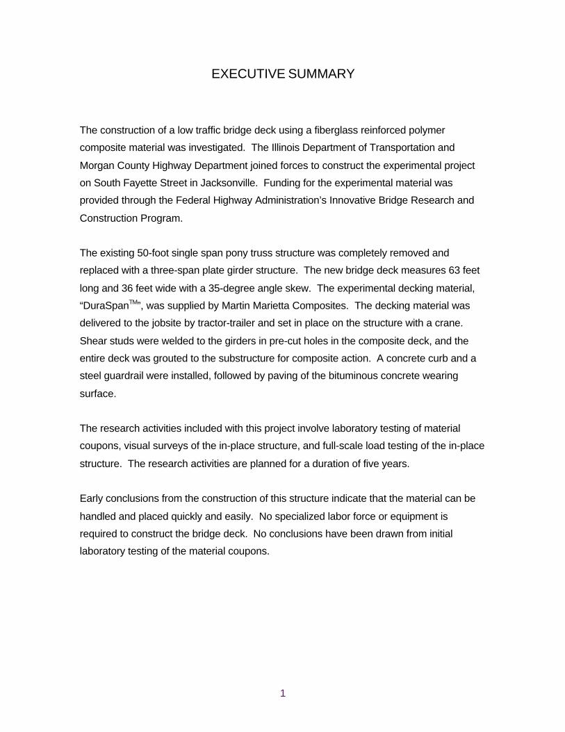
EXECUTIVE SUMMARY
The construction of a low traffic bridge deck using a fiberglass reinforced polymer
composite material was investigated. The Illinois Department of Transportation and
Morgan County Highway Department joined forces to construct the experimental project
on South Fayette Street in Jacksonville. Funding for the experimental material was
provided through the Federal Highway Administration’s Innovative Bridge Research and
Construction Program.
The existing 50-foot single span pony truss structure was completely removed and
replaced with a three-span plate girder structure. The new bridge deck measures 63 feet
long and 36 feet wide with a 35-degree angle skew. The experimental decking material,
“DuraSpanTM”, was supplied by Martin Marietta Composites. The decking material was
delivered to the jobsite by tractor-trailer and set in place on the structure with a crane.
Shear studs were welded to the girders in pre-cut holes in the composite deck, and the
entire deck was grouted to the substructure for composite action. A concrete curb and a
steel guardrail were installed, followed by paving of the bituminous concrete wearing
surface.
The research activities included with this project involve laboratory testing of material
coupons, visual surveys of the in-place structure, and full-scale load testing of the in-place
structure. The research activities are planned for a duration of five years.
Early conclusions from the construction of this structure indicate that the material can be
handled and placed quickly and easily. No specialized labor force or equipment is
required to construct the bridge deck. No conclusions have been drawn from initial
laboratory testing of the material coupons.
2
INTRODUCTION
The city of Jacksonville, Illinois had experienced problems with flooding along the Town
Brook for many years. In particular, the structure carrying South Fayette Street over the
Town Brook had flooded numerous times in recent years. This pony truss bridge, shown
in Figure 1, was also in dire need of repair or replacement. Severe corrosion of the
reinforcing steel and spalling of the existing concrete deck led to posted weight limits for
the bridge. A project was initiated to replace the existing structure with a wider and longer
structure. This project also called for raising the elevation of the structure, and the
surrounding roadways, to prevent the recurring flood problems.
Figure 1Existing Pony Truss Bridge
In an attempt to reduce the project cost to the City of Jacksonville, an application was
made for federal funding through the Innovative Bridge Research and Construction
Program (IBRC). In order to fulfill the requirements for the funding, an experimental
material or construction process was required with the bridge construction. The decision
was made to use a fiberglass reinforced polymer (FRP) composite material for the bridge
deck. The selected composite material was “DuraSpanTM” from Martin Marietta
Composites. This report will cover the planning and design of the bridge, construction of
the bridge with the FRP deck, and the project costs.

3
OBJECTIVE
The objective of this project is to evaluate the constructibility and performance of an FRP
composite bridge deck system. This objective will be accomplished through construction
inspection, performance monitoring, and laboratory testing. This report details the
constructibility of the bridge deck system.
This project was constructed with partial funding from the Federal Highway
Administration’s IBRC program. This program was established to assist state, county,
and local municipalities’ incorporate innovative materials into their bridge projects. The
intent of the program is to reduce the life-cycle cost of bridges, increase safety, and
reduce congestion and delays associated with bridge construction.

4
PLANNING AND DESIGN
The plan for this project included replacing the existing structure on South Fayette Street
over the Town Brook, and raising the elevation of the structure nearly six feet to place it
above the 100-year high water elevation. South Fayette Street was raised and improved,
as well as the adjacent intersection with West Chambers Street. Utility adjustments and
earthwork were also required to complete the project.
The existing single-span pony truss structure was believed to be over 70 years old. The
existing structure was 50 feet long and 24 feet wide. The bridge incorporated concrete
column foundations to support the pony trusses. The pony trusses were secured together
with hot rivets. The design of the new bridge included a three-span structure with W14 X
61 steel plate girders, the FRP composite decking material, and a bituminous concrete
wearing surface. The new bridge is 63 feet long and 36 feet wide with a 35° right-ahead
skew. The AASHTO design loading for the new bridge includes the dead load plus 25
pounds per square foot for a future wearing surface and an HS20 live load plus impact.
Deflection tolerances of the deck were limited to L / 800 where L is the distance between
adjacent plate girders.
The “DuraSpanTM” composite material is a pultruded material composed of E-glass fibers
in various fiber orientations and an isophthalic polyester resin binder. The pultrusion
process involves pulling the glass fibers through a liquid resin bath and a set of heated
dies to form the final geometric shape (tube) of the material, shown in Figure 2.

5
Figure 2“DuraSpanTM” Geometric Shape
The pultrusion process is a continuous process. Therefore, the tube must be cut to the
proper length while the pultrusion process continues. Once several tubes of the material
have been fabricated, they are bonded together in the factory with a two-part polyurethane
adhesive to form a panel. The length of these panels is typically equal to the width of the
bridge. The width of the panels varies from eight to ten feet based on transportation
constraints. The final steps are cutting the shear stud pockets and applying a surface
finish.
16 inches
7.66
inch
es
12 inches

6
CONSTRUCTION
The construction of this project took place in the Fall of 2001. South Fayette Street and
the adjacent intersection with West Chambers Street were completely closed to through
traffic for the duration of construction. The existing structure was removed in mid-
September and metal shell piles were driven for the new piers. The metal shell piles were
filled and encased with concrete as shown in Figure 3.
Figure 3Concrete Encased Metal Shell Piles
The pier caps and abutments were formed and finished, followed by placement of the
steel plate girders on October 17th. Once the girders were set and anchored down, the
contractor began tack welding L 2” X 3” X 0.125” angle irons onto the top flanges of the
steel girders as shown in Figure 4. These angle irons were used as a temporary support
for the FRP panels until they could be grouted in place. The void created by the angle
irons was eventually filled with non-shrink grout in order to provide full contact between
the steel girders and the FRP panels.

7
Figure 4Angle Irons Tack Welded to the Girder Top Flange
The FRP panels arrived at the project by tractor-trailer, as shown in Figure 5, on October
30th. The panels were unloaded from the tractor-trailer by crane and stacked on the
ground in their order of placement on the bridge. The first step was to clean all of the
areas that would become part of a field joint with an acetone wash. Following the acetone
wash, a primer coat was applied to the same areas. This process was completed with
small paint rollers as seen in Figure 6.
Figure 5Panel Delivery by Tractor-Trailer
8
Figure 6Prime Coat Application
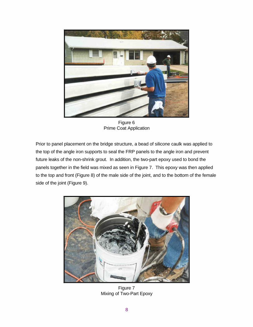
Prior to panel placement on the bridge structure, a bead of silicone caulk was applied to
the top of the angle iron supports to seal the FRP panels to the angle iron and prevent
future leaks of the non-shrink grout. In addition, the two-part epoxy used to bond the
panels together in the field was mixed as seen in Figure 7. This epoxy was then applied
to the top and front (Figure 8) of the male side of the joint, and to the bottom of the female
side of the joint (Figure 9).
Figure 7Mixing of Two-Part Epoxy

9
Figure 8Epoxy Application to the Male Side of the Panel
Figure 9Epoxy Application to the Female Side of the Panel
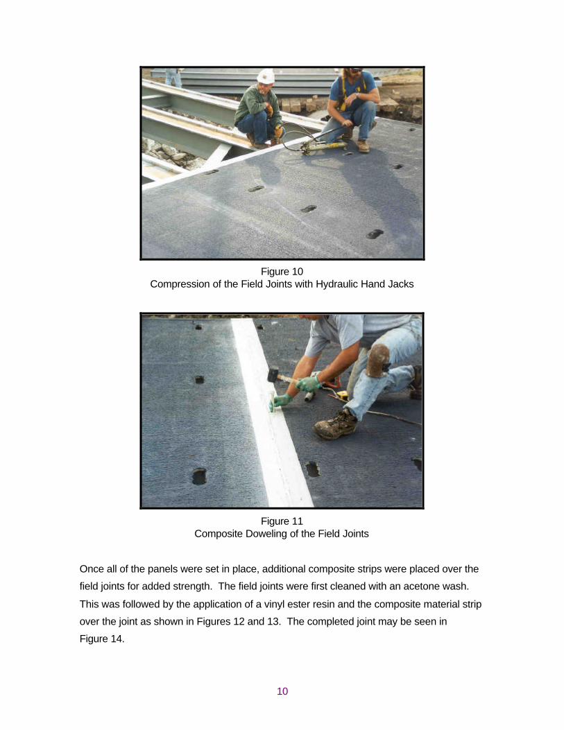
The FRP panels were set in place on the bridge with a crane and the joints were
compressed together with hydraulic hand jacks as shown in Figure 10. Once a panel was
in its final position, composite dowels were secured through the joint to hold the panels in
place as shown in Figure 11.
10
Figure 10Compression of the Field Joints with Hydraulic Hand Jacks
Figure 11Composite Doweling of the Field Joints
Once all of the panels were set in place, additional composite strips were placed over the
field joints for added strength. The field joints were first cleaned with an acetone wash.
This was followed by the application of a vinyl ester resin and the composite material strip
over the joint as shown in Figures 12 and 13. The completed joint may be seen in
Figure 14.

11
Figure 12Vinyl Ester Resin Application to Field Joint
Figure 13Composite Material Strip Used Over Field Joints
12
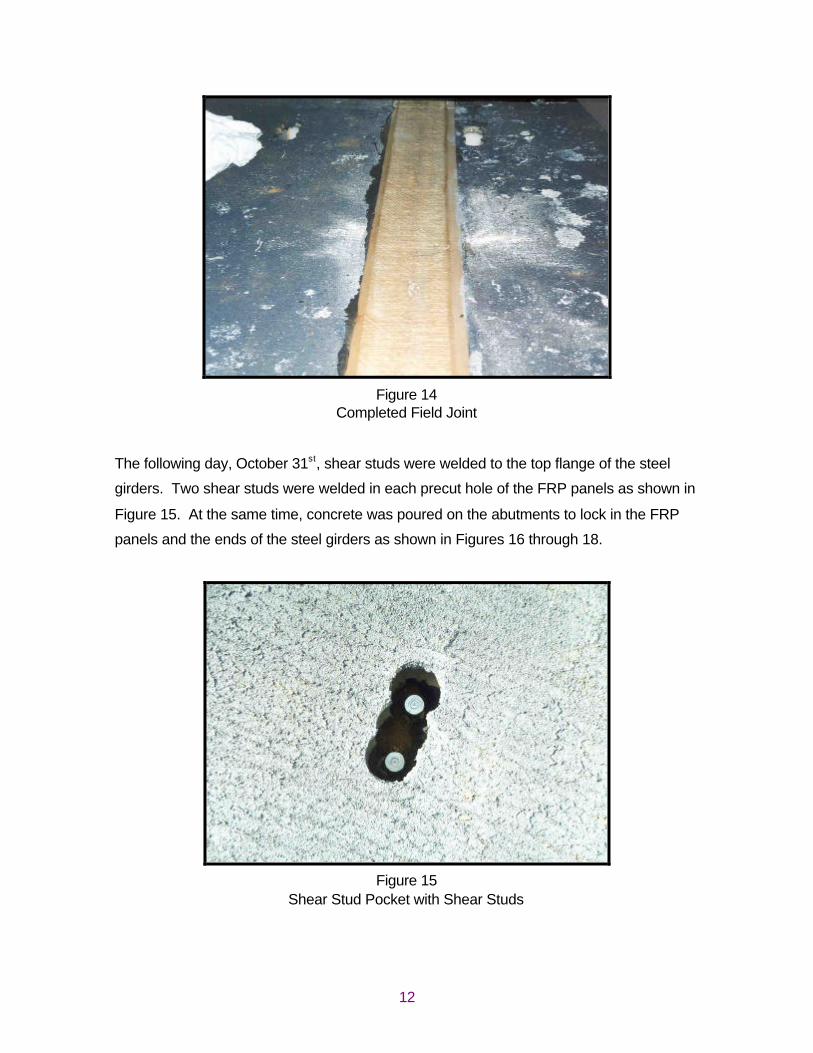
Figure 14Completed Field Joint
The following day, October 31st, shear studs were welded to the top flange of the steel
girders. Two shear studs were welded in each precut hole of the FRP panels as shown in
Figure 15. At the same time, concrete was poured on the abutments to lock in the FRP
panels and the ends of the steel girders as shown in Figures 16 through 18.
Figure 15Shear Stud Pocket with Shear Studs

13
Figure 16Forming for Abutments and Encasement of Girder Ends
Figure 17Styrofoam Dams in FRP Panels to Prevent Concrete and Grout Flow
14
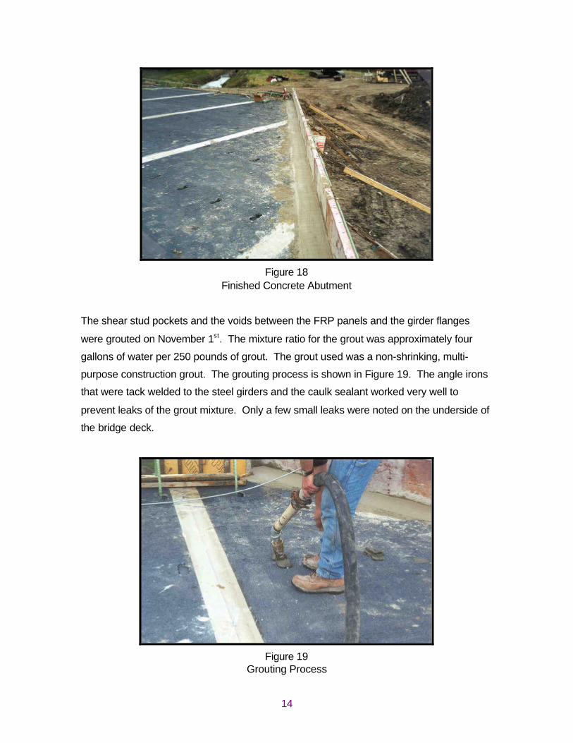
Figure 18Finished Concrete Abutment
The shear stud pockets and the voids between the FRP panels and the girder flanges
were grouted on November 1st. The mixture ratio for the grout was approximately four
gallons of water per 250 pounds of grout. The grout used was a non-shrinking, multi-
purpose construction grout. The grouting process is shown in Figure 19. The angle irons
that were tack welded to the steel girders and the caulk sealant worked very well to
prevent leaks of the grout mixture. Only a few small leaks were noted on the underside of
the bridge deck.
Figure 19Grouting Process

15
Following the grouting of the FRP panels to the steel girders and shear studs, the curb
and guardrail were installed. Epoxy coated steel reinforcing bars were grouted into the
outside shear stud pocket, as shown in Figure 20, to secure the curb to the bride deck.
The concrete curb was formed and poured by hand. The steel tubing used for the
guardrail was bolted to the concrete curb and the fascia girder as shown in Figure 21.
Figure 20Steel Reinforcement for the Concrete Curb
Figure 21Bolted Connections for the Steel Guardrail

16
Approximately one month was spent raising the elevation of the approach pavements and
improving the adjacent intersection. Storm sewers, potable water lines, and overhead
utilities were relocated as part of the improvement.
The final construction process, before opening the bridge deck to traffic, was to pave the
bituminous concrete wearing surface. The roadway crown across the bridge surface was
constructed with bituminous concrete, since the FRP panels were placed flat. The
centerline bituminous concrete thickness is 4.25-inches, while the thickness adjacent to
the curb is 1.25-inches. The paving of the surface course may be seen in Figure 22. The
breakdown roller shown in Figure 22 was run in “static” mode across the bridge to prevent
unnecessary vibrations of the bridge deck. The bridge deck was opened to traffic in mid-
December.
Figure 22Bituminous Concrete Paving of the Surface Course

17
PROJECT COSTS
The material costs for constructing this type of bridge decking system are more than for a
traditional concrete deck. The increased cost of manufacturing and supplying the FRP
material increased the initial cost of the project over traditional construction methods.
Outlined below in Table 1 are the construction costs for the bridge superstructure
elements. Also included is the total initial FRP bridge deck construction cost and an
approximate concrete bridge deck construction cost for the same structure.
Table 1Project Construction Costs
Item Units Cost Per Unit Total Cost
Furnish and Erect FRP Deck Panels 2,180 sq. ft. $125.01 $272,521.80
Shear Stud Connectors 464 each $4.22 $1,958.08
Epoxy Coated Reinforcement Bars 1,450 lbs $1.29 $1,870.50
Superstructure Concrete 13 cu. yd. $1,032.90 $13,427.70
Nonshrink Grout for FRP Panels 8.7 cu. yd. $1,243.39 $10,817.49
Bituminous Binder Course 22 ton $89.71 $1,973.62
Bituminous Surface Course 18 ton $56.99 $1,025.82
QC / QA Bituminous 40 ton $2.11 $84.40
Total FRP Deck Construction Cost $303,679.41
Approximate Concrete Deck Construction Cost $107,795.00

18
RESEARCH ACTIVITIES
A significant objective for this project is the performance monitoring of the completed
structure. Several laboratory tests and experiments have been selected to accomplish
this portion of the objective. Material coupon samples have been collected to complete
the testing over the course of five years. The following laboratory tests have been
selected to monitor the FRP composite material integrity.
OUTDOOR WEATHERING
The material coupon samples that have been obtained for testing will be exposed to
weather and sunlight according to ASTM D 1435. The samples will be mounted in a
45-degree angle, south facing rack for durations of one, two, three, four, and five years.
At the end of each time duration, selected samples will be removed in order to determine
the following properties.
TENSILE PROPERTIES
The tensile properties of selected material samples will be tested according to
ASTM D 638. Five samples in the longitudinal fiber direction and five samples in the
transverse fiber direction will be tested for their ultimate tensile strength, elongation, and
modulus of elasticity.
FLEXURAL PROPERTIES
The flexural properties of selected material samples will be tested according to
ASTM D 790. Four samples in the longitudinal fiber direction and placed flat and four
samples in the longitudinal fiber direction and placed on edge will be tested for their
ultimate flexural strength, deflection, and modulus of elasticity.

19
COMPRESSIVE PROPERTIES
The compressive properties of selected material samples will be tested according to
ASTM D 695. Five samples in the longitudinal fiber direction and five samples in the
transverse fiber direction will be tested for their ultimate compressive strength and amount
of compression.
IGNITION LOSS
The fiber and resin contents, respectively, will be determined on two selected material
samples according to ASTM D 2584.
WATER ABSORPTION
The two-hour boiling water immersion and long term immersion, respectively, of three
selected material samples will be determined according to ASTM D 570. These tests will
be performed with the initial group of samples only.
GLOSS AND COLOR LOSS
The changes in gloss and color of selected material samples will also be determined. The
gloss testing will be according to ASTM D 523. The color testing will be performed using
a color spectrophotometer with a 45-degree circumferential / zero-degree geometry,
illuminate C, and two-degree observer angle. The color instrument shall measure the
visible spectrum from 380 to 720 nm with a wavelength measurement interval and
spectral band pass of 10 nm.
In addition to the laboratory research and testing, additional testing will be performed on
the full-scale structure. Visual surveys of the completed structure will be performed on an
annual basis to document any distressed areas or noticeable changes. Full-scale load
testing is also planned for the structure.

20
CONCLUSIONS
An experimental fiberglass reinforced polymer composite material was used to construct a
bridge deck on South Fayette Street in Jacksonville. This structure crosses the Town
Brook, which has been prone to flooding problems in recent years. The experimental FRP
composite material selected for this project was “DuraSpanTM” from Martin Marietta
Composites. The construction of the bridge took place between September and
December of 2001.
After monitoring construction of this bridge deck with the experimental material, the
following conclusions were made:
1. The construction of the bridge deck was expedited. The entire deck surface was
delivered and placed on the bridge in one day.
2. The material is easy to work with and easy to place.
3. The use of angle irons for fillets and grout dams worked well.
4. The use of pre-cut shear stud pockets in the FRP panels worked well.