fiberwavinessinnanotube …r.d.bradshaw1,l.c.brinson* department of mechanicalengineering,...
TRANSCRIPT
Fiber waviness in nanotube-reinforced polymer composites—I:Modulus predictions using effective nanotube properties
F.T. Fisher, R.D. Bradshaw1, L.C. Brinson*
Department of Mechanical Engineering, Northwestern University, 2145 Sheridan Road, Evanston, IL 60208, USA
Received 30 September 2002; received in revised form 20 December 2002; accepted 10 January 2003
Abstract
Results in the literature demonstrate that substantial improvements in the mechanical behavior of polymers have been attained
through the addition of small amounts of carbon nanotubes as a reinforcing phase. This suggests the possibility of new, extremelylightweight carbon nanotube-reinforced polymers with mechanical properties comparable to those of traditional carbon-fibercomposites. Motivated by micrographs showing that embedded nanotubes often exhibit significant curvature within the polymer, wehave developed a model combining finite element results and micromechanical methods to determine the effective reinforcing mod-
ulus of a wavy embedded nanotube. This effective reinforcing modulus (ERM) is then used within a multiphase micromechanicsmodel to predict the effective modulus of a polymer reinforced with a distribution of wavy nanotubes. We found that even slightnanotube curvature significantly reduces the effective reinforcement when compared to straight nanotubes. These results suggest that
nanotube waviness may be an additional mechanism limiting the modulus enhancement of nanotube-reinforced polymers.# 2003 Elsevier Ltd. All rights reserved.
Keywords: A. Nanostructures; A. PMCs; B. Mechanical properties; B. Modeling; C. FEA
1. Introduction
Since their discovery in the early 1990s, carbon nano-tubes have excited scientists and engineers with theirwide range of unusual physical properties. These out-standing physical properties are a direct result of thenear-perfect microstructure of the nanotubes (NTs),which at the atomic scale can be thought of as a hex-agonal sheet of carbon atoms rolled into a seamless,quasi-one-dimensional cylindrical shape. Besides theirextremely small size, it has been suggested that carbonnanotubes are half as dense as aluminum, have tensilestrengths 20 times that of high strength steel alloys, havecurrent carrying capacities 1000 times that of copper,and transmit heat twice as well as pure diamond [1]. Totake advantage of this unique combination of size andproperties, a wide variety of applications have beenproposed for carbon nanotubes, including chemical and
genetic probes, field emission tips, mechanical memory,ultrafine sensors, hydrogen and ion storage, scanningprobe microscope tips, and as structural materials [1]. Ithas been suggested that nanotechnology, largely fueledby the remarkable properties of carbon nanotubes, mayultimately transform technology to a greater extent thanthe advances of the silicon revolution [2].In this paper we will focus on the use of carbon
nanotubes as the reinforcing phase in a bulk polymermaterial. Preliminary experimental results suggest thatsmall amounts of carbon nanotubes can significantlyenhance the overall mechanical behavior of the polymer[3–7]; we refer to these materials as nanotube reinforcedpolymers (NRPs). Other types of nanoscale inclusions,while not directly addressed in this paper, have also beenproposed as candidate filler materials. NRPs hold vastpotential as structural materials due to the extremelyhigh strength- and modulus-to-weight ratios that arelikely to be achieved with such materials. Other potentialadvantages of NRPs include multifunctionality,increased energy absorbance, higher toughness, and easeof manufacturing (particularly if the NRPs can be pro-cessed using traditional polymer techniques). Despite thechallenges which these materials present in terms of
0266-3538/03/$ - see front matter # 2003 Elsevier Ltd. All rights reserved.
doi:10.1016/S0266-3538(03)00069-1
Composites Science and Technology 63 (2003) 1689–1703
www.elsevier.com/locate/compscitech
* Corresponding author. Tel.: +1-847-467-2347; fax: +1-847-491-
3915.
E-mail address: [email protected] (L.C. Brinson).1 Current address: Department of Mechanical Engineering, Uni-
versity of Louisville, Louisville, KY 40292, USA.
modeling, processing, and most notably the availabilityand cost of the raw nanotube material, the preliminaryresults and inherent potential suggest that further studyof NRPs is warranted.To increase our understanding of these materials it is
useful to develop models to predict the effective prop-erties of NRPs, enabling detailed study of the materialresponse. One means to accomplish this is the extensionof traditional micromechanics and composite modelsthat address particular characteristics of these materials.Because micrograph images show that the embeddednanotubes remain highly curved when dispersed in apolymer (see Fig. 1), we have developed a hybrid finiteelement-micromechanical model that allows the effectsof embedded nanotube waviness to be incorporated intotraditional micromechanical techniques. Using experi-mental data we demonstrate that nanotube wavinesscan limit NRP modulus enhancement, resulting inimprovements that (while still significant) are currentlyless than predicted by traditional theories.
At the moment it is impossible to differentiate theimpact of nanotube waviness from competing reinforce-ment-limiting mechanisms such as a weak NT–polymerinterface, poor NT dispersion, and processing-inducedNT degradation in existing NRP experimental data.Nevertheless, our results provide a clear picture of howrelatively moderate waviness can hinder the effectivenessof NTs as structural reinforcement. While the workreported here is an application of a micromechanicsmethod to a nanostructured material, the integration ofatomic scale modeling could readily be adapted intosuch an analysis. In the future a fusion of true nanoscaleand microscale modeling will provide even more insightinto this material behavior.The following section discusses the properties of car-
bon nanotubes and issues related to their use in struc-tural polymers. The micromechanical and finite elementmodels that were used in this work, and a description ofhow inclusion waviness was integrated into micro-mechanical property predictions, will follow. We thenpresent results showing how the effective reinforcingmodulus of an embedded wavy nanotube is dependenton geometry and other parameters. Finally, the effectivemodulus predictions for NRPs with various nanotubeorientations are predicted and compared to experi-mental data.
2. Background
Due to the inherent strength of the carbon–carbonbond and the potential of a defect-free microstructure, ithas been suggested that nanotubes may approach theo-retical limits for many important mechanical properties,including axial stiffness and tensile strength. Largeincreases in the fracture strain and toughness, andsuperior electrical/thermal properties, are other poten-tial benefits of using NTs as the filler material in apolymer-based composite. One possible near-termapplication of carbon nanotubes, which is the motiva-tion for this work, is as a low volume-fraction structuralreinforcement in a polymer matrix.Carbon nanotubes can be broadly classified into three
categories: single-walled nanotubes (SWNT), multi-walled nanotubes (MWNT), and nanotube bundles orropes (see Fig. 2). SWNTs consist of single layer ofcarbon atoms wrapped into a cylindrical shape, whileMWNTs consist of several concentric layers (or shells)of individual carbon nanotubes that are weakly coupledto each other through van der Waals forces. Typically,however, the nanotubes are found to have self-orga-nized into crystalline bundles [8], consisting of several tohundreds of SWNTs or MWNTs arranged in a closest-packed two-dimensional lattice. Within these bundlesthe nanotubes normally display a monodisperse rangeof diameters, with adjacent tubes weakly coupled via
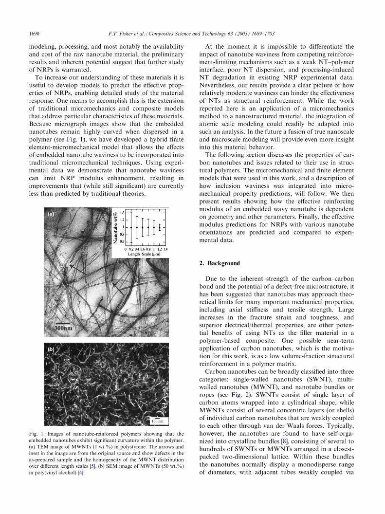
Fig. 1. Images of nanotube-reinforced polymers showing that the
embedded nanotubes exhibit significant curvature within the polymer.
(a) TEM image of MWNTs (1 wt.%) in polystyrene. The arrows and
inset in the image are from the original source and show defects in the
as-prepared sample and the homogeneity of the MWNT distribution
over different length scales [5]. (b) SEM image of MWNTs (50 wt.%)
in poly(vinyl alcohol) [4].
1690 F.T. Fisher et al. / Composites Science and Technology 63 (2003) 1689–1703
van der Waal interactions. While not modeled in thecontinuum approach presented here, explicit differencesin the structural behavior of these various NT forms,particularly when embedded within a polymer, will needto be addressed in the future. While SWNTs are moresusceptible to bending due to their extremely smallcross-sections, more intimate contact with the polymermatrix may lead to more efficient load transfer betweenthe two phases. For MWNTs and NT bundles, inter-layer sliding (so-called ‘‘sword and sheath’’ slippage [9])and weak intertube coupling, respectively, could limittheir potential as structural reinforcement.Much of the early work studying the mechanical
properties of nanotubes utilized computational methodssuch as molecular dynamics and ab initio models. Thesemodels focused primarily on SWNTs because of theincrease in computational resources necessary to modellarger systems. In general these computational studieshave found nominal values for the axial Young’s mod-ulus on the order of 1 TPa, with values for the Poissonratio approximately 0.20 to 0.30 [10,11].2 A differentapproach calculated elastic moduli of roughly 1 TPa forSWNTs and MWNTs, while SWNT bundle moduliranged between 0.4 and 0.8 TPa and were dependent onthe diameter of the individual tubes [14]. Most of thesemodels assume defect-free nanotubes; nanotubes with asignificant number of defects (such as those producedvia chemical vapor deposition methods) are expected tohave much lower moduli [15]. Recently, progress hasbeen realized in the manipulating and testing of indivi-dual nanotubes and nanotube bundles [15–20]; in gen-eral these experiments have validated the predictedmodulus values (see Table 1). We note that computa-tional and experimental moduli values are typicallyreported based on a hollow shell geometry with anindividual shell thickness of 0.34 nm, the interlayerspacing in graphite.
Optimal material properties will be achievable only ifthe nanotubes can be separated and dispersed within thematrix and their orientation controlled. Current methodsto separate and disperse individual nanotubes includeusing sonication, polar solvents, and surfactants. Align-ment of the nanotubes with a polymer has been achievedusing shear flow [21], tensile loading above the glasstransition temperature of the polymer [22], and a com-bination of solvent casting and melt mixing technique[23]. The impact of these processing techniques on thestructural integrity of the nanotubes, and the NT–poly-mer interface, are the subjects of ongoing research.Another topic currently being studied is the NT–poly-
mer interface and load transfer between the polymer andthe nanotubes [3–5,24–27]. While poor load transfer forMWNTs and SWNT ropes embedded in a polymer hasbeen attributed to the relative slipping of individual tubeswithin the MWNT and the rope, respectively [3,26], otherresearchers have found evidence of promising nanotube–polymer interactions in composite materials. For exam-ple, a strong interface between MWNTs and poly-styrene (PS) [5] and polyhydroxyaminoether (PHAE)[22] has been reported. Analysis of SWNT bundle-PMMA thin films found that PMMA was able tointercalate within the bundles, which would likelyenhance the interface between the nanotube and poly-mer phases [28]; significant wetting and interfacialadhesion for SWNT bundles embedded in an epoxyresin has also been reported [29]. A recent moleculardynamics study suggested that polymer morphology,and specifically the helical wrapping of the polymeraround the nanotubes, was a key factor influencing thestrength of the interface [27]. Functionalization of theNT to increase its chemical reactivity has also beenproposed as means to further enhance nanotube-polymerinteraction [30]. While it has been estimated that the stresstransfer efficiency between NTs and a polymer matrixcould be an order of magnitude larger than typicallymeasured in conventional fiber-based composites [31], amuch better understanding of the factors which influencethe nanotube-polymer interface is required.The issues identified above indicate several key
aspects that will influence our ability to design andmodel materials that fully exploit the potential ofnanoscale reinforcements. One issue which has nottypically been associated with the modeling of NRPs,but which seems critical based on micrograph images ofthese materials, is the characteristic waviness or curva-ture of embedded nanotubes (see Fig. 1). To addressthis question we have developed a model that integratesthe waviness of the nanotubes into micromechanicalpredictions of the NRP effective modulus. Our resultssuggest that such waviness, while potentially beneficialfor other applications (i.e. strength), can drasticallyreduce the effective stiffness of the NRP when comparedto straight nanotube models.
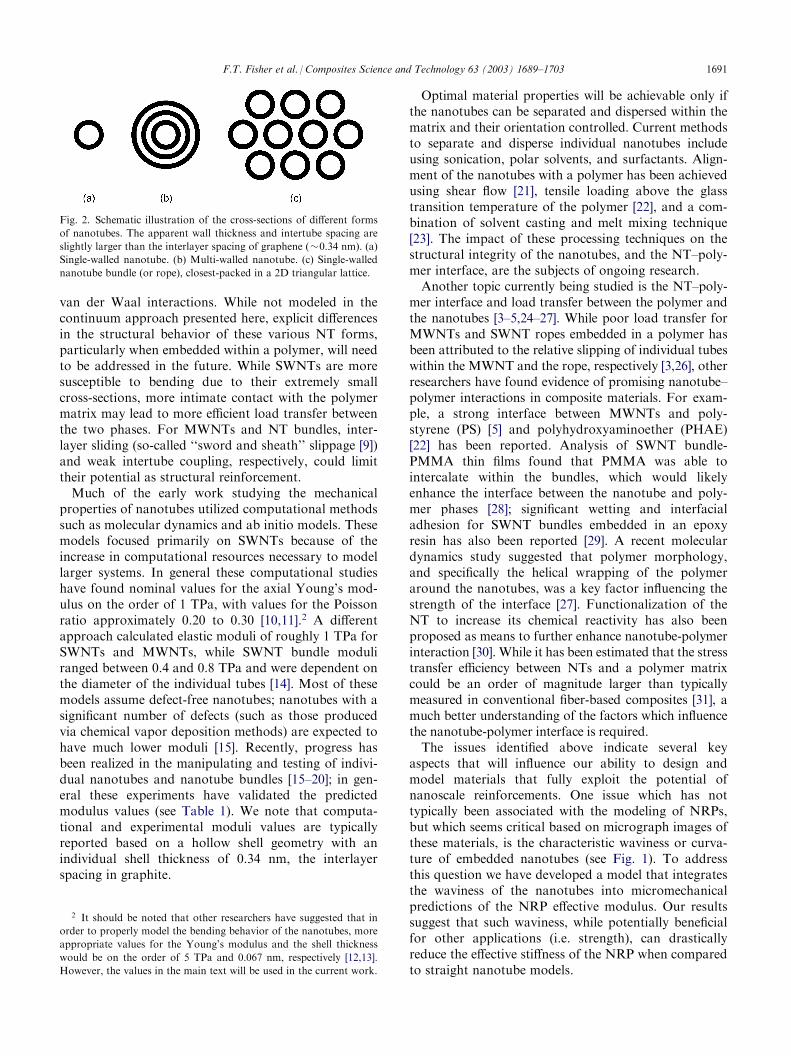
Fig. 2. Schematic illustration of the cross-sections of different forms
of nanotubes. The apparent wall thickness and intertube spacing are
slightly larger than the interlayer spacing of graphene (�0.34 nm). (a)
Single-walled nanotube. (b) Multi-walled nanotube. (c) Single-walled
nanotube bundle (or rope), closest-packed in a 2D triangular lattice.
2 It should be noted that other researchers have suggested that in
order to properly model the bending behavior of the nanotubes, more
appropriate values for the Young’s modulus and the shell thickness
would be on the order of 5 TPa and 0.067 nm, respectively [12,13].
However, the values in the main text will be used in the current work.
F.T. Fisher et al. / Composites Science and Technology 63 (2003) 1689–1703 1691

3. The model
Based on the discussion of the last section, we areinterested in using micromechanical techniques to studythe effective elastic moduli of nanotube-reinforcedpolymers. The basis of the model is to determine theeffective reinforcing modulus (ERM) of an embeddedwavy nanotube; that is, a representative value denotedEERM that accounts for the reduction in reinforcementprovided by the wavy nanotube in comparison to thereinforcement provided by a straight NT (of modulusENT).
3 Thus while the nanotube modulus ENT is amaterial property, the effective reinforcing modulusEERM (EERM4ENT) is a material parameter that is afunction of the geometry of the wavy nanotube andother variables (see the Appendix). This effective mod-ulus is then available for use in standard micro-mechanical models in lieu of the true (actual) nanotubemodulus. While such a procedure can be applied ingeneral to any class of curved and wavy inclusions,embedded nanotubes and NRPs are the focus of thepresent discussion.In this regard, we note the results of several research-
ers who found that continuum models provide usefulinsight into nanotube behavior [33,34], despite the dis-crete nature of their atomic structure.4 To simplify thegeometry we will treat the nanotube geometry as a solid
element of circular cross-sectional area, which implicitlyintroduces two simplifications into the analysis. First,treating the inclusion as a solid cylinder neglects thehollow nature of the nanotubes. Second, by modelingthe nanotube as a continuum we are disregarding thespecific form of the nanotube (SWNT, MWNT, orbundle) and neglecting any possible relative motionbetween individual shells or tubes in a MWNT and anNT bundle, respectively. Each of these assumptionssuggests that EERM as calculated here is an ‘‘upperbound’’ for the given model, in that accounting for thehollow nature of the NTs or modeling sliding of thetubes or shells would further reduce the effective stiff-ness of a wavy nanotube. Thus nanotube waviness maybe even more significant than the results presented inthis work would indicate. While this approach willhighlight the impact of nanotube waviness on the effec-tive modulus of an NRP, a more rigorous analysis thataccounts for the discrete nature of the nanotube and theatomic interaction between the nanotube and polymer iswarranted and will be the subject of future work.In addition to the continuum assumption, several
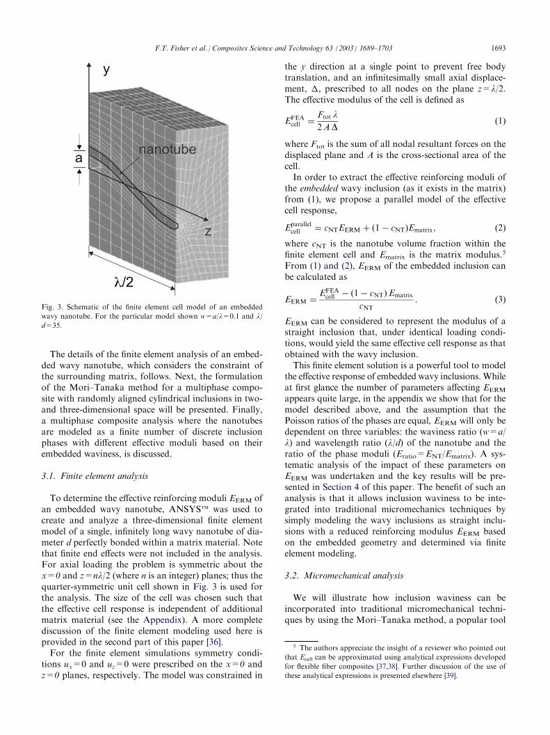
other simplifications are invoked throughout this workto aid in the interpretation of the results. The individualphase materials are modeled as linear elastic and iso-tropic, and perfect bonding between the phases isassumed. The waviness of a nanotube of diameter d willbe introduced by prescribing an embedded NT shape ofthe form y ¼ a cos 2� z=lð Þ, where l is the sinusoidalwavelength and z is the fiber axial direction (see Fig. 3).Unless otherwise noted, Poisson ratios of 0.30 wereassumed for all phases in the simulations; this value isrepresentative of a wide range of polymer materials andis consistent with the range of values estimated for car-bon nanotubes. This assumption will be discussed inmore detail later in this paper.
Table 1
Experimental values for the Young’s modulus of carbon nanotubes
Type of CNT
Method Modulus values CommentsLaser ablated SWNTs (diameters
1.0–1.5 nm) [16]
Amplitude of thermal vibration
within a TEM
1.3–0.4/+0.6 TPa
Weighted average value of1.25 TPa
Laser ablation SWNT bundles [17]
Nanostressing stage within a SEM 320–1470 GPa, mean of 1002 GPa Load carried by SWNTs on ropeperimeter
Carbon arc SWNT bundles (bundle
diameters 3–20 nm) [18]
Beam-bending via AFM
�1 TPa for 3 nm diameter, decreasingto <0.1 GPa for larger diameter
Estimated bundle shear moduli
�1 GPa
Carbon arc MWNTs [19]
Electromechanical deflection andresonance within a TEM
�1 TPa for small diameter (<10 nm)
to 0.1 TPa for large diameter (>30 nm)
Modulus a strong function of
diameter
Carbon arc MWNTs [20]
Nanostressing stage within a SEM Modulus of outer shell from �270 to�950 GPa
‘‘Sword-in-sheath’’ failure
mechanism
Carbon arc and CVD MWNTs [15]
Beam-bending via AFM CVD: �10–50 GPa Order of magnitude increase afterannealing CVD NTs at 2500 �C
Arc: 810–160/+410 GPa3 This effective reinforcing modulus EERM is identical to what we
have called the wavy nanotube modulus (Ewavy) in previous work [32].4 Others have found a large number of atomic layers was necessary
to justify the treatment of the nanotube as a continuum [35]. However,
for the purposes of moduli predictions we believe that a continuum
assumption is an acceptable simplification. Other mechanical beha-
vior, such as crack propagation and fracture, will undoubtedly be
more dependent on atomic structure and may be especially ill-suited
for such an assumption.
1692 F.T. Fisher et al. / Composites Science and Technology 63 (2003) 1689–1703
The details of the finite element analysis of an embed-ded wavy nanotube, which considers the constraint ofthe surrounding matrix, follows. Next, the formulationof the Mori–Tanaka method for a multiphase compo-site with randomly aligned cylindrical inclusions in two-and three-dimensional space will be presented. Finally,a multiphase composite analysis where the nanotubesare modeled as a finite number of discrete inclusionphases with different effective moduli based on theirembedded waviness, is discussed.
3.1. Finite element analysis
To determine the effective reinforcing moduli EERM ofan embedded wavy nanotube, ANSYSTM was used tocreate and analyze a three-dimensional finite elementmodel of a single, infinitely long wavy nanotube of dia-meter d perfectly bonded within a matrix material. Notethat finite end effects were not included in the analysis.For axial loading the problem is symmetric about thex=0 and z=nl/2 (where n is an integer) planes; thus thequarter-symmetric unit cell shown in Fig. 3 is used forthe analysis. The size of the cell was chosen such thatthe effective cell response is independent of additionalmatrix material (see the Appendix). A more completediscussion of the finite element modeling used here isprovided in the second part of this paper [36].For the finite element simulations symmetry condi-
tions ux=0 and uz=0 were prescribed on the x=0 andz=0 planes, respectively. The model was constrained in
the y direction at a single point to prevent free bodytranslation, and an infinitesimally small axial displace-ment, �, prescribed to all nodes on the plane z=l/2.The effective modulus of the cell is defined as
EFEAcell ¼
Ftot l2AD
ð1Þ
where Ftot is the sum of all nodal resultant forces on thedisplaced plane and A is the cross-sectional area of thecell.In order to extract the effective reinforcing moduli of
the embedded wavy inclusion (as it exists in the matrix)from (1), we propose a parallel model of the effectivecell response,
Eparallelcell ¼ cNTEERM þ 1� cNTð ÞEmatrix; ð2Þ
where cNT is the nanotube volume fraction within thefinite element cell and Ematrix is the matrix modulus.
5
From (1) and (2), EERM of the embedded inclusion canbe calculated as
EERM ¼EFEA
cell � 1� cNTð ÞEmatrix
cNT: ð3Þ
EERM can be considered to represent the modulus of astraight inclusion that, under identical loading condi-tions, would yield the same effective cell response as thatobtained with the wavy inclusion.This finite element solution is a powerful tool to model
the effective response of embedded wavy inclusions.Whileat first glance the number of parameters affecting EERMappears quite large, in the appendix we show that for themodel described above, and the assumption that thePoisson ratios of the phases are equal, EERM will only bedependent on three variables: the waviness ratio (w=a/l) and wavelength ratio (l/d) of the nanotube and theratio of the phase moduli (Eratio=ENT/Ematrix). A sys-tematic analysis of the impact of these parameters onEERM was undertaken and the key results will be pre-sented in Section 4 of this paper. The benefit of such ananalysis is that it allows inclusion waviness to be inte-grated into traditional micromechanics techniques bysimply modeling the wavy inclusions as straight inclu-sions with a reduced reinforcing modulus EERM basedon the embedded geometry and determined via finiteelement modeling.
3.2. Micromechanical analysis
We will illustrate how inclusion waviness can beincorporated into traditional micromechanical techni-ques by using the Mori–Tanaka method, a popular tool
Fig. 3. Schematic of the finite element cell model of an embedded
wavy nanotube. For the particular model shown w=a/l=0.1 and l/d=35.
5 The authors appreciate the insight of a reviewer who pointed out
that Ecell can be approximated using analytical expressions developed
for flexible fiber composites [37,38]. Further discussion of the use of
these analytical expressions is presented elsewhere [39].
F.T. Fisher et al. / Composites Science and Technology 63 (2003) 1689–1703 1693
for the analysis of multi-phase materials [40,41]. TheMori–Tanaka method has been used by a wide range ofresearchers to model the effective behavior of compo-sites, and allows the average stress fields and overalleffective stiffness of a composite with a non-diluteconcentration of inclusions to be determined. Of parti-cular interest for the current work is that the Mori–Tanaka method can readily model composites withmultiple inclusion phases and random orientations ofinclusions.For completeness we highlight those expressions from
the Mori–Tanaka method of interest below. For a morecomplete derivation the reader is directed to the litera-ture [41]. Here we assume that the composite is com-prised of N phases; the matrix will be denoted as phase 0with a corresponding stiffness C0 and volume fractionf0, while an arbitrary rth inclusion phase (where r=1 toN�1) has a stiffness of Cr and a volume fraction fr. Forsimplicity we will assume that all fiber phases can bemodeled as infinitely long cylindrical inclusions.Following the standard Mori–Tanaka derivation, one
can develop the expression for the dilute strain-concen-tration factor of the rth phase, Adil
r , which relates thevolume-averaged strain in the rth inclusion to that ofthe matrix such that
"rh i ¼ Adilr "0h i; ð4Þ
where
Adilr ¼ I þ SrC
�10 Cr � C0ð Þ
� ��1; ð5Þ
I is the fourth order identity tensor, Sr is the standardEshelby tensor (see the Appendix), and brackets h i
denote a volume-averaged quantity. Given (5), theeffective composite stiffness C as determined using theMori–Tanaka method is given as
C ¼XN�1
r¼0
fr CrAdilr
� � ! XN�1
r¼0
fr Adilr
� � !�1
ð6Þ
where the curly brackets fg represent an orientationalaverage6 (necessary to account for random orientationsof inclusions) and Adil
0 ¼ I by definition. Once the com-ponents of the effective stiffness have been determined,the standard relationships can be used to find the cor-responding elastic constants.
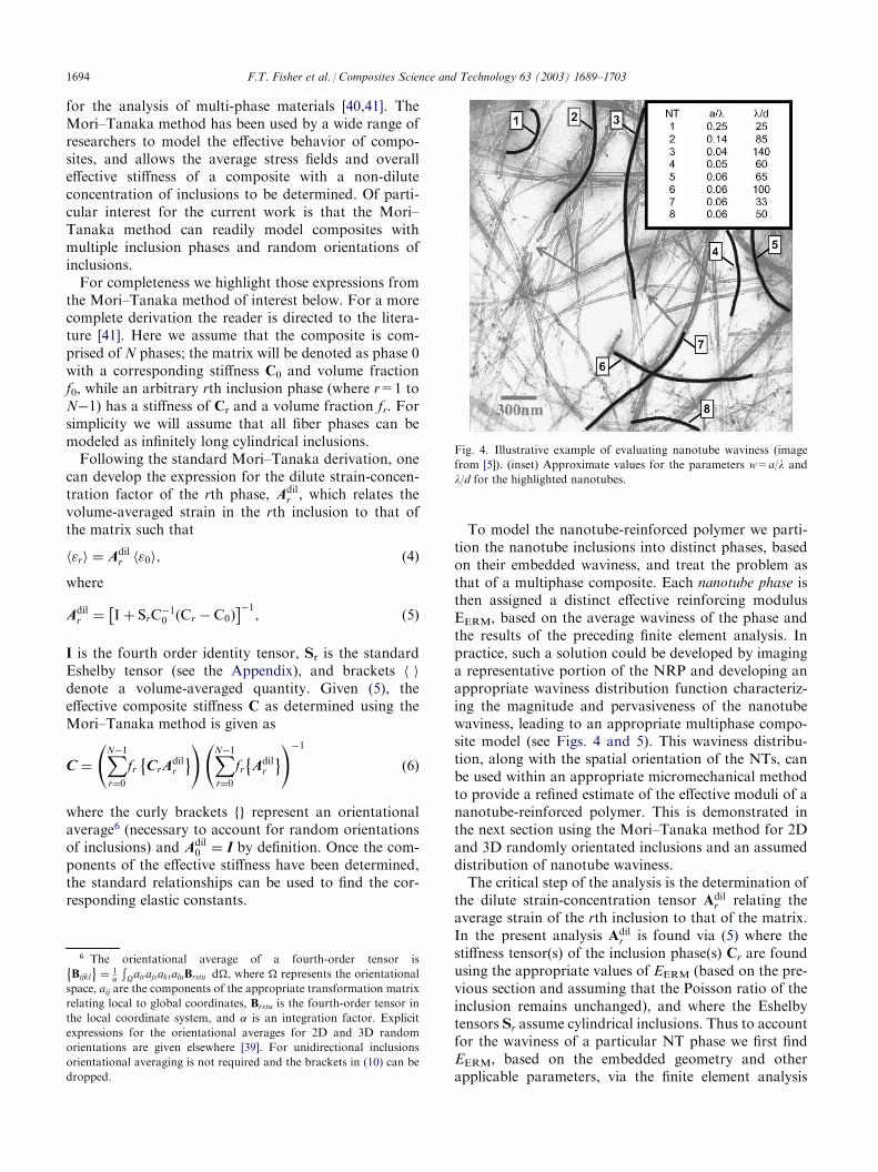
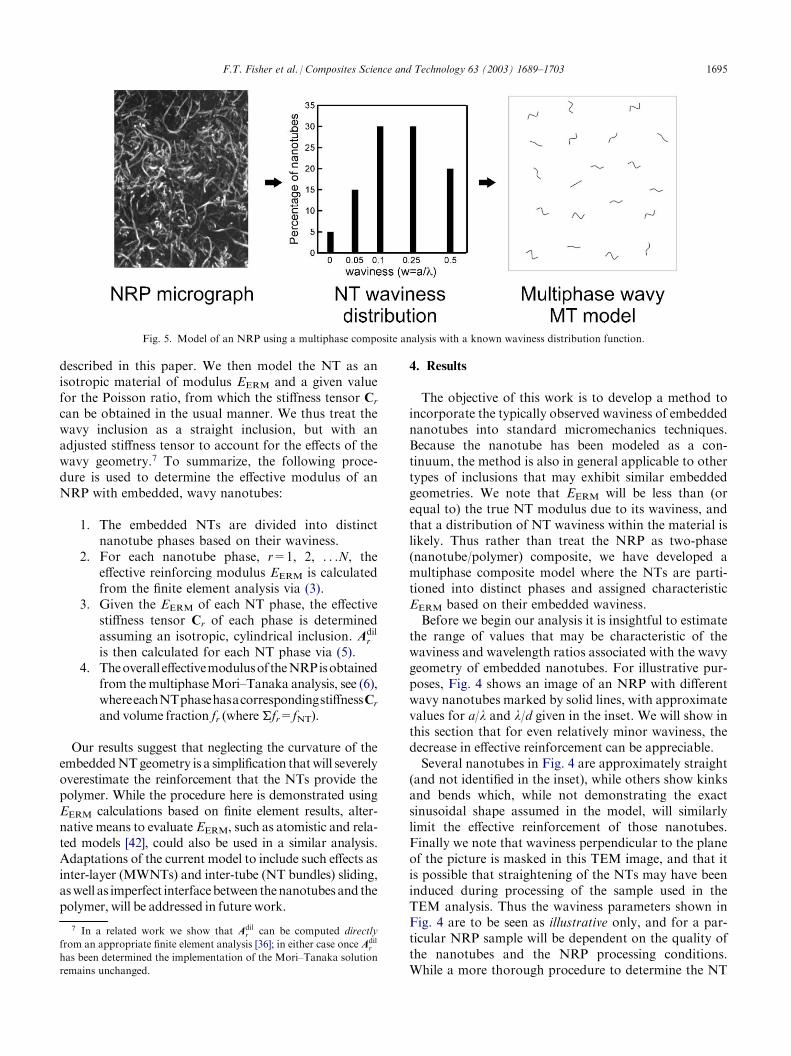
To model the nanotube-reinforced polymer we parti-tion the nanotube inclusions into distinct phases, basedon their embedded waviness, and treat the problem asthat of a multiphase composite. Each nanotube phase isthen assigned a distinct effective reinforcing modulusEERM, based on the average waviness of the phase andthe results of the preceding finite element analysis. Inpractice, such a solution could be developed by imaginga representative portion of the NRP and developing anappropriate waviness distribution function characteriz-ing the magnitude and pervasiveness of the nanotubewaviness, leading to an appropriate multiphase compo-site model (see Figs. 4 and 5). This waviness distribu-tion, along with the spatial orientation of the NTs, canbe used within an appropriate micromechanical methodto provide a refined estimate of the effective moduli of ananotube-reinforced polymer. This is demonstrated inthe next section using the Mori–Tanaka method for 2Dand 3D randomly orientated inclusions and an assumeddistribution of nanotube waviness.The critical step of the analysis is the determination of
the dilute strain-concentration tensor Adilr relating the
average strain of the rth inclusion to that of the matrix.In the present analysis Adil
r is found via (5) where thestiffness tensor(s) of the inclusion phase(s) Cr are foundusing the appropriate values of EERM (based on the pre-vious section and assuming that the Poisson ratio of theinclusion remains unchanged), and where the Eshelbytensors Sr assume cylindrical inclusions. Thus to accountfor the waviness of a particular NT phase we first findEERM, based on the embedded geometry and otherapplicable parameters, via the finite element analysis
Fig. 4. Illustrative example of evaluating nanotube waviness (image
from [5]). (inset) Approximate values for the parameters w=a/l andl/d for the highlighted nanotubes.
6 The orientational average of a fourth-order tensor is
Bijkl
� �¼ 1
�
ÐOairajsaktaluBrstu d�, where � represents the orientational
space, aij are the components of the appropriate transformation matrix
relating local to global coordinates, Brstu is the fourth-order tensor in
the local coordinate system, and � is an integration factor. Explicitexpressions for the orientational averages for 2D and 3D random
orientations are given elsewhere [39]. For unidirectional inclusions
orientational averaging is not required and the brackets in (10) can be
dropped.
1694 F.T. Fisher et al. / Composites Science and Technology 63 (2003) 1689–1703
described in this paper. We then model the NT as anisotropic material of modulus EERM and a given valuefor the Poisson ratio, from which the stiffness tensor Cr
can be obtained in the usual manner. We thus treat thewavy inclusion as a straight inclusion, but with anadjusted stiffness tensor to account for the effects of thewavy geometry.7 To summarize, the following proce-dure is used to determine the effective modulus of anNRP with embedded, wavy nanotubes:
1. The embedded NTs are divided into distinct
nanotube phases based on their waviness.2. For each nanotube phase, r=1, 2, . . .N, the
effective reinforcing modulus EERM is calculatedfrom the finite element analysis via (3).3. Given the EERM of each NT phase, the effective
stiffness tensor Cr of each phase is determinedassuming an isotropic, cylindrical inclusion. Adilr
is then calculated for each NT phase via (5).4. Theoverall effectivemodulusof theNRPisobtained
from themultiphaseMori–Tanaka analysis, see (6),whereeachNTphasehasacorrespondingstiffnessCrand volume fraction fr (where!fr=fNT).
Our results suggest that neglecting the curvature of theembeddedNTgeometry is a simplification thatwill severelyoverestimate the reinforcement that the NTs provide thepolymer. While the procedure here is demonstrated usingEERM calculations based on finite element results, alter-native means to evaluate EERM, such as atomistic and rela-ted models [42], could also be used in a similar analysis.Adaptations of the current model to include such effects asinter-layer (MWNTs) and inter-tube (NT bundles) sliding,aswell as imperfect interfacebetween thenanotubes and thepolymer, will be addressed in future work.
4. Results
The objective of this work is to develop a method toincorporate the typically observed waviness of embeddednanotubes into standard micromechanics techniques.Because the nanotube has been modeled as a con-tinuum, the method is also in general applicable to othertypes of inclusions that may exhibit similar embeddedgeometries. We note that EERM will be less than (orequal to) the true NT modulus due to its waviness, andthat a distribution of NT waviness within the material islikely. Thus rather than treat the NRP as two-phase(nanotube/polymer) composite, we have developed amultiphase composite model where the NTs are parti-tioned into distinct phases and assigned characteristicEERM based on their embedded waviness.Before we begin our analysis it is insightful to estimate
the range of values that may be characteristic of thewaviness and wavelength ratios associated with the wavygeometry of embedded nanotubes. For illustrative pur-poses, Fig. 4 shows an image of an NRP with differentwavy nanotubes marked by solid lines, with approximatevalues for a/l and l/d given in the inset. We will show inthis section that for even relatively minor waviness, thedecrease in effective reinforcement can be appreciable.Several nanotubes in Fig. 4 are approximately straight
(and not identified in the inset), while others show kinksand bends which, while not demonstrating the exactsinusoidal shape assumed in the model, will similarlylimit the effective reinforcement of those nanotubes.Finally we note that waviness perpendicular to the planeof the picture is masked in this TEM image, and that itis possible that straightening of the NTs may have beeninduced during processing of the sample used in theTEM analysis. Thus the waviness parameters shown inFig. 4 are to be seen as illustrative only, and for a par-ticular NRP sample will be dependent on the quality ofthe nanotubes and the NRP processing conditions.While a more thorough procedure to determine the NT
Fig. 5. Model of an NRP using a multiphase composite analysis with a known waviness distribution function.
7 In a related work we show that Adilr can be computed directly
from an appropriate finite element analysis [36]; in either case once Adilr
has been determined the implementation of the Mori–Tanaka solution
remains unchanged.
F.T. Fisher et al. / Composites Science and Technology 63 (2003) 1689–1703 1695
waviness for a particular sample may be warranted, forthe purposes of this paper a hypothetical waviness dis-tribution is sufficient to demonstrate the impact ofnanotube waviness on the effective NRP modulus.With this in mind, the remainder of this section is
divided into two parts. In the first part we discussimpact of nanotube waviness and other model para-meters on EERM. We will then use these results to com-pare the predictions of our micromechanical analysis,accounting for the embedded nanotube geometry, withpredictions obtained assuming straight nanotube inclu-sions and with published experimental data for NRPeffective modulus.
4.1. Effective reinforcing modulus EERM
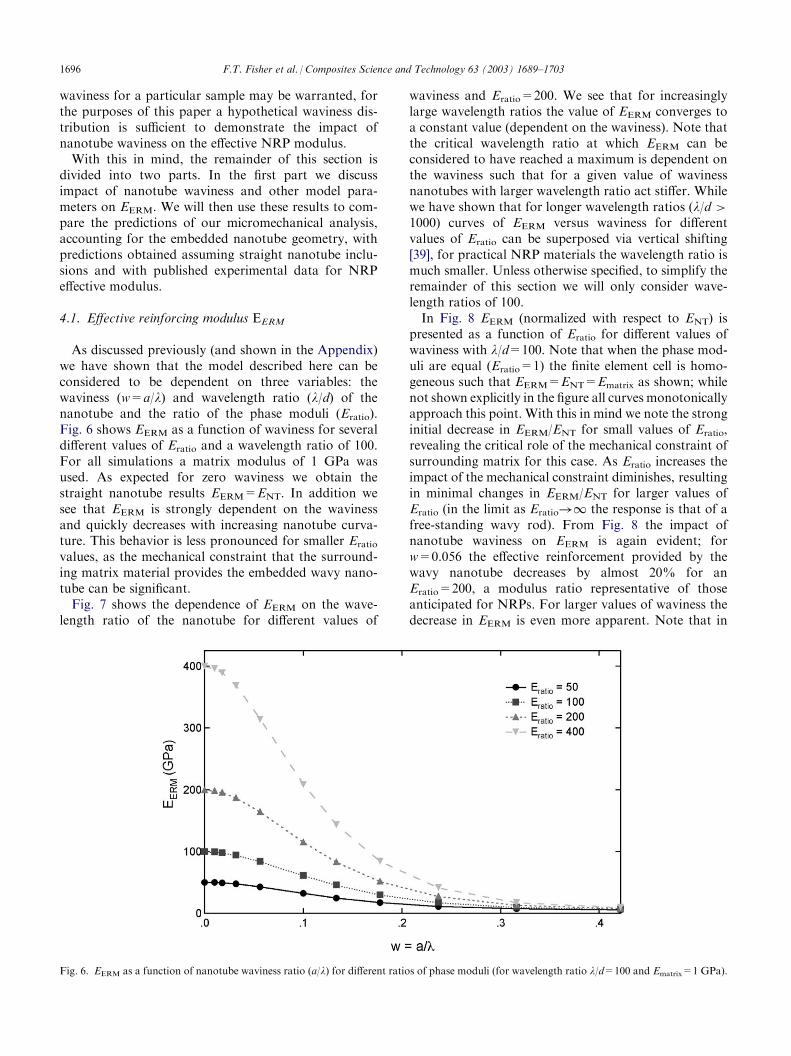
As discussed previously (and shown in the Appendix)we have shown that the model described here can beconsidered to be dependent on three variables: thewaviness (w=a/l) and wavelength ratio (l/d) of thenanotube and the ratio of the phase moduli (Eratio).Fig. 6 shows EERM as a function of waviness for severaldifferent values of Eratio and a wavelength ratio of 100.For all simulations a matrix modulus of 1 GPa wasused. As expected for zero waviness we obtain thestraight nanotube results EERM=ENT. In addition wesee that EERM is strongly dependent on the wavinessand quickly decreases with increasing nanotube curva-ture. This behavior is less pronounced for smaller Eratiovalues, as the mechanical constraint that the surround-ing matrix material provides the embedded wavy nano-tube can be significant.Fig. 7 shows the dependence of EERM on the wave-
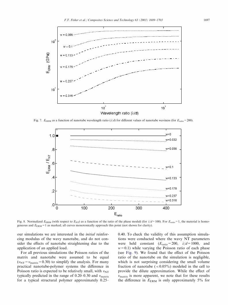
length ratio of the nanotube for different values of
waviness and Eratio=200. We see that for increasinglylarge wavelength ratios the value of EERM converges toa constant value (dependent on the waviness). Note thatthe critical wavelength ratio at which EERM can beconsidered to have reached a maximum is dependent onthe waviness such that for a given value of wavinessnanotubes with larger wavelength ratio act stiffer. Whilewe have shown that for longer wavelength ratios (l/d >1000) curves of EERM versus waviness for differentvalues of Eratio can be superposed via vertical shifting[39], for practical NRP materials the wavelength ratio ismuch smaller. Unless otherwise specified, to simplify theremainder of this section we will only consider wave-length ratios of 100.In Fig. 8 EERM (normalized with respect to ENT) is
presented as a function of Eratio for different values ofwaviness with l/d=100. Note that when the phase mod-uli are equal (Eratio=1) the finite element cell is homo-geneous such that EERM=ENT=Ematrix as shown; whilenot shown explicitly in the figure all curves monotonicallyapproach this point. With this in mind we note the stronginitial decrease in EERM/ENT for small values of Eratio,revealing the critical role of the mechanical constraint ofsurrounding matrix for this case. As Eratio increases theimpact of the mechanical constraint diminishes, resultingin minimal changes in EERM/ENT for larger values ofEratio (in the limit as Eratio!1 the response is that of afree-standing wavy rod). From Fig. 8 the impact ofnanotube waviness on EERM is again evident; forw=0.056 the effective reinforcement provided by thewavy nanotube decreases by almost 20% for anEratio=200, a modulus ratio representative of thoseanticipated for NRPs. For larger values of waviness thedecrease in EERM is even more apparent. Note that in
Fig. 6. EERM as a function of nanotube waviness ratio (a/l) for different ratios of phase moduli (for wavelength ratio l/d=100 and Ematrix=1 GPa).
1696 F.T. Fisher et al. / Composites Science and Technology 63 (2003) 1689–1703
our simulations we are interested in the initial reinfor-cing modulus of the wavy nanotube, and do not con-sider the effects of nanotube straightening due to theapplication of an applied load.For all previous simulations the Poisson ratios of the
matrix and nanotube were assumed to be equal(NT=matrix=0.30) to simplify the analysis. For manypractical nanotube-polymer systems the difference inPoisson ratio is expected to be relatively small, with NTtypically predicted in the range of 0.20–0.30 and matrixfor a typical structural polymer approximately 0.25–
0.40. To check the validity of this assumption simula-tions were conducted where the wavy NT parameterswere held constant (Eratio=200, l/d=1000, andw=0.1) while varying the Poisson ratio of each phase(see Fig. 9). We found that the effect of the Poissonratio of the nanotube on the simulation is negligible,which is not surprising considering the small volumefraction of nanotube (<0.05%) modeled in the cell toprovide the dilute approximation. While the effect ofmatrix is more apparent, we note that for these resultsthe difference in EERM is only approximately 5% for
Fig. 8. Normalized EERM (with respect to ENT) as a function of the ratio of the phase moduli (for l/d=100). For Eratio=1, the material is homo-
geneous and EERM=1 as marked; all curves monotonically approach this point (not shown for clarity).
Fig. 7. EERM as a function of nanotube wavelength ratio (l/d) for different values of nanotube waviness (for Eratio=200).
F.T. Fisher et al. / Composites Science and Technology 63 (2003) 1689–1703 1697
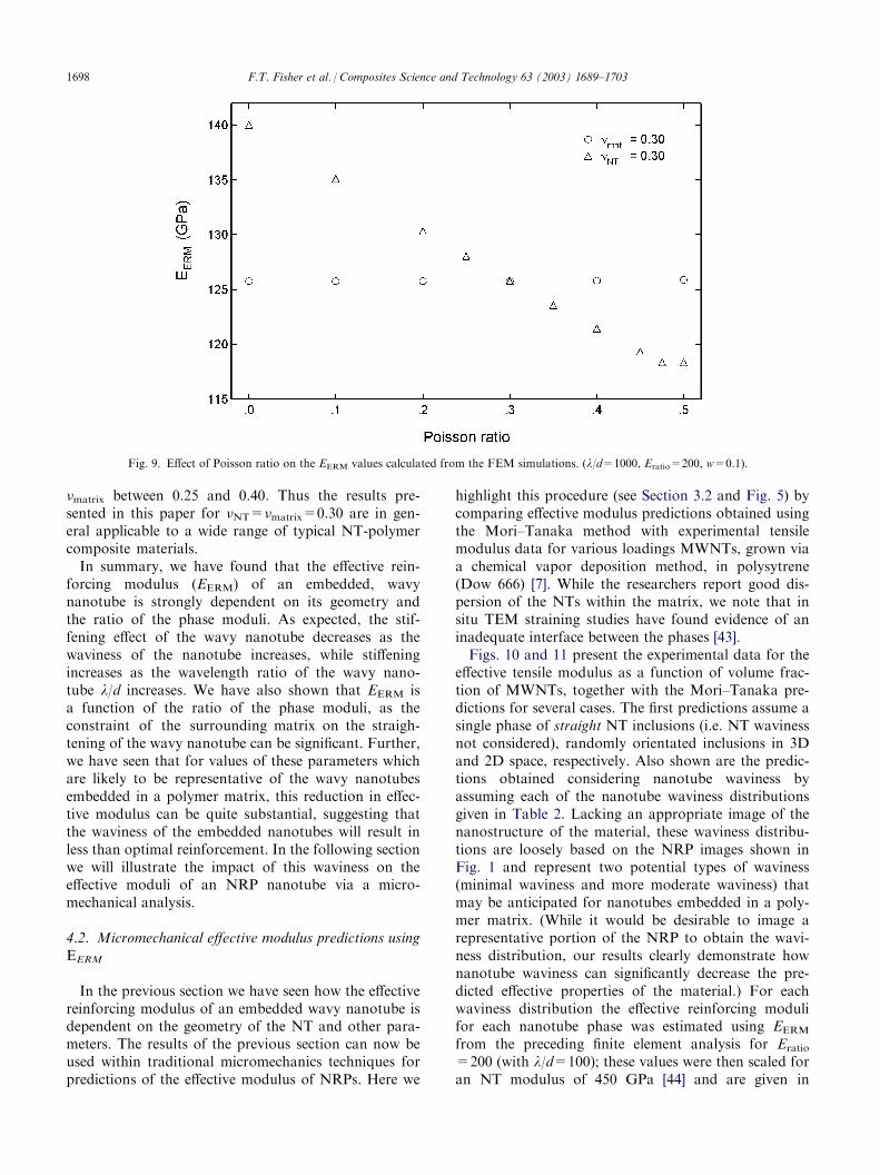
matrix between 0.25 and 0.40. Thus the results pre-sented in this paper for NT=matrix=0.30 are in gen-eral applicable to a wide range of typical NT-polymercomposite materials.In summary, we have found that the effective rein-
forcing modulus (EERM) of an embedded, wavynanotube is strongly dependent on its geometry andthe ratio of the phase moduli. As expected, the stif-fening effect of the wavy nanotube decreases as thewaviness of the nanotube increases, while stiffeningincreases as the wavelength ratio of the wavy nano-tube l/d increases. We have also shown that EERM isa function of the ratio of the phase moduli, as theconstraint of the surrounding matrix on the straigh-tening of the wavy nanotube can be significant. Further,we have seen that for values of these parameters whichare likely to be representative of the wavy nanotubesembedded in a polymer matrix, this reduction in effec-tive modulus can be quite substantial, suggesting thatthe waviness of the embedded nanotubes will result inless than optimal reinforcement. In the following sectionwe will illustrate the impact of this waviness on theeffective moduli of an NRP nanotube via a micro-mechanical analysis.
4.2. Micromechanical effective modulus predictions usingEERM
In the previous section we have seen how the effectivereinforcing modulus of an embedded wavy nanotube isdependent on the geometry of the NT and other para-meters. The results of the previous section can now beused within traditional micromechanics techniques forpredictions of the effective modulus of NRPs. Here we
highlight this procedure (see Section 3.2 and Fig. 5) bycomparing effective modulus predictions obtained usingthe Mori–Tanaka method with experimental tensilemodulus data for various loadings MWNTs, grown viaa chemical vapor deposition method, in polysytrene(Dow 666) [7]. While the researchers report good dis-persion of the NTs within the matrix, we note that insitu TEM straining studies have found evidence of aninadequate interface between the phases [43].Figs. 10 and 11 present the experimental data for the
effective tensile modulus as a function of volume frac-tion of MWNTs, together with the Mori–Tanaka pre-dictions for several cases. The first predictions assume asingle phase of straight NT inclusions (i.e. NT wavinessnot considered), randomly orientated inclusions in 3Dand 2D space, respectively. Also shown are the predic-tions obtained considering nanotube waviness byassuming each of the nanotube waviness distributionsgiven in Table 2. Lacking an appropriate image of thenanostructure of the material, these waviness distribu-tions are loosely based on the NRP images shown inFig. 1 and represent two potential types of waviness(minimal waviness and more moderate waviness) thatmay be anticipated for nanotubes embedded in a poly-mer matrix. (While it would be desirable to image arepresentative portion of the NRP to obtain the wavi-ness distribution, our results clearly demonstrate hownanotube waviness can significantly decrease the pre-dicted effective properties of the material.) For eachwaviness distribution the effective reinforcing modulifor each nanotube phase was estimated using EERMfrom the preceding finite element analysis for Eratio=200 (with l/d=100); these values were then scaled foran NT modulus of 450 GPa [44] and are given in
Fig. 9. Effect of Poisson ratio on the EERM values calculated from the FEM simulations. (l/d=1000, Eratio=200, w=0.1).
1698 F.T. Fisher et al. / Composites Science and Technology 63 (2003) 1689–1703
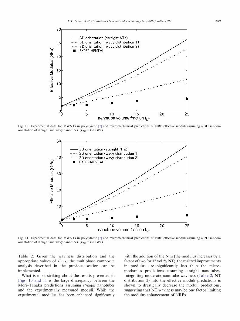
Table 2. Given the waviness distribution and theappropriate values of EERM the multiphase compositeanalysis described in the previous section can beimplemented.What is most striking about the results presented in
Figs. 10 and 11 is the large discrepancy between theMori–Tanaka predictions assuming straight nanotubesand the experimentally measured moduli. While theexperimental modulus has been enhanced significantly
with the addition of the NTs (the modulus increases by afactor of two for 15 vol.%NT), the realized improvementsin modulus are significantly less than the micro-mechanics predictions assuming straight nanotubes.Integrating moderate nanotube waviness (Table 2, NTdistribution 2) into the effective moduli predictions isshown to drastically decrease the moduli predictions,suggesting that NT waviness may be one factor limitingthe modulus enhancement of NRPs.
Fig. 11. Experimental data for MWNTs in polysytrene [7] and micromechanical predictions of NRP effective moduli assuming a 2D random
orientation of straight and wavy nanotubes. (ENT=450 GPa).
Fig. 10. Experimental data for MWNTs in polystyrene [7] and micromechanical predictions of NRP effective moduli assuming a 3D random
orientation of straight and wavy nanotubes. (ENT=450 GPa).
F.T. Fisher et al. / Composites Science and Technology 63 (2003) 1689–1703 1699
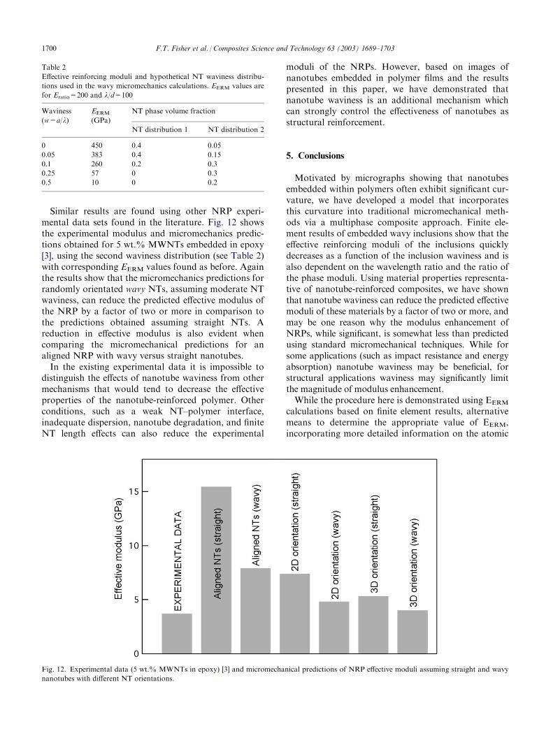
Similar results are found using other NRP experi-mental data sets found in the literature. Fig. 12 showsthe experimental modulus and micromechanics predic-tions obtained for 5 wt.% MWNTs embedded in epoxy[3], using the second waviness distribution (see Table 2)with corresponding EERM values found as before. Againthe results show that the micromechanics predictions forrandomly orientated wavy NTs, assuming moderate NTwaviness, can reduce the predicted effective modulus ofthe NRP by a factor of two or more in comparison tothe predictions obtained assuming straight NTs. Areduction in effective modulus is also evident whencomparing the micromechanical predictions for analigned NRP with wavy versus straight nanotubes.In the existing experimental data it is impossible to
distinguish the effects of nanotube waviness from othermechanisms that would tend to decrease the effectiveproperties of the nanotube-reinforced polymer. Otherconditions, such as a weak NT–polymer interface,inadequate dispersion, nanotube degradation, and finiteNT length effects can also reduce the experimental
moduli of the NRPs. However, based on images ofnanotubes embedded in polymer films and the resultspresented in this paper, we have demonstrated thatnanotube waviness is an additional mechanism whichcan strongly control the effectiveness of nanotubes asstructural reinforcement.
5. Conclusions
Motivated by micrographs showing that nanotubesembedded within polymers often exhibit significant cur-vature, we have developed a model that incorporatesthis curvature into traditional micromechanical meth-ods via a multiphase composite approach. Finite ele-ment results of embedded wavy inclusions show that theeffective reinforcing moduli of the inclusions quicklydecreases as a function of the inclusion waviness and isalso dependent on the wavelength ratio and the ratio ofthe phase moduli. Using material properties representa-tive of nanotube-reinforced composites, we have shownthat nanotube waviness can reduce the predicted effectivemoduli of these materials by a factor of two or more, andmay be one reason why the modulus enhancement ofNRPs, while significant, is somewhat less than predictedusing standard micromechanical techniques. While forsome applications (such as impact resistance and energyabsorption) nanotube waviness may be beneficial, forstructural applications waviness may significantly limitthe magnitude of modulus enhancement.While the procedure here is demonstrated using EERM
calculations based on finite element results, alternativemeans to determine the appropriate value of EERM,incorporating more detailed information on the atomic
Fig. 12. Experimental data (5 wt.% MWNTs in epoxy) [3] and micromechanical predictions of NRP effective moduli assuming straight and wavy
nanotubes with different NT orientations.
Table 2
Effective reinforcing moduli and hypothetical NT waviness distribu-
tions used in the wavy micromechanics calculations. EERM values are
for Eratio=200 and l/d=100
Waviness
(w=a/l)
EERM(GPa)NT phase volume fraction
NT distribution 1
NT distribution 20
450 0.4 0.050.05
383 0.4 0.150.1
260 0.2 0.30.25
57 0 0.30.5
10 0 0.21700 F.T. Fisher et al. / Composites Science and Technology 63 (2003) 1689–1703
level interactions in the material, could also be used in asimilar analysis. Adaptations of the current model toinclude transversely isotropic NT behavior, inter-layer(MWNTs) and inter-tube (NT bundles) sliding, finiteend effects, and imperfect bonding between the nano-tubes and the polymer, were not addressed here andwarrant further work. While at the moment it is impos-sible to isolate the effects of nanotube waviness fromother reinforcement-limiting mechanisms, these resultsdemonstrate that nanotube waviness can severely limitthe effective modulus of nanotube-reinforced polymers.Finally, our results suggest that methods of NRP fab-
rication that reduce the waviness of embedded NTswould allow the NTs to provide maximum structuralreinforcement. One may also hypothesize that nanotubewaviness may be one reason why NRP modulusenhancement has sometimes only been reported at highertemperatures [4]; if compressive stresses developed dur-ing the polymer cure introduce bending (and hence cur-vature) into the nanotubes, significant NT reinforcementmay only be realized as the NTs straighten due to poly-mer softening at elevated temperatures.
Acknowledgements
This work was supported by the NASA Langley Com-putationalMaterials Nanotechnology Program.Wewouldlike to thank Dr. Rodney Andrews of the University ofKentucky for advanced access to his experimental data andDr. Linda Schadler of RPI for fruitful discussions.
Appendix A. Convergence of EERM for a sufficiently
large matrix
In order to eliminate the size of the finite elementmodel as a parameter in the analysis, it is necessary toshow that EERM converges for a sufficiently largematrix. Consider a finite element cell of an embeddedwavy nanotube (see Fig. 3), where for simplicity weredefine the length of the cell as L (to eliminate carryinga factor of two in our analysis below). We assume thatthe matrix boundary at the top and bottom of the cell issuch that fields at these boundaries are undisturbed bythe presence of the nanotube, and denote the volumes ofthe NT, matrix, and total cell as VNT, Vmat, and V,respectively. We now apply an infinitesimally small uni-form strain "z in the fiber axial direction and measurethe total resultant force Ftot necessary to cause thisstrain. From (1) and (2), EERM for this particular cell is
EERM1¼
Ftot L
V "z�
Vmat
VEmat
VNT
V
¼Ftot L
VNT "z�
Vmat
VNTEmat: ð7Þ
Now consider a second finite element cell, identical tothe previous cell except that additional matrix material,with a volume Vmat2, has been evenly divided betweenthe top and bottom of the first cell. Due to the size ofthe first cell this additional matrix material is alsounaffected by the presence of the wavy nanotube, thusthe force necessary to produce a uniform strain "z in thisadditional material is F2 ¼
Emat Vmat2"z
L . Using the totalforce that must be applied to the second cell (Ftot + F2),one can show that the EERM1=EERM2. Thus for asufficiently large matrix EERM is independent of thesize of the finite element cell; all simulations met thiscondition (typically VNT <0.01% in the finite ele-ment cell).
Appendix B. Reduction of EERM parameters for the finite
element analysis
Because we have shown that EERM converges given asufficiently large cell, it is sufficient to consider themodel parameters that influence Ecell
FEA in the presentanalysis. Assuming isotropic behavior of the phasematerials, the model at first appears to the dependent onseven parameters, such that
EFEAcell ¼ f ENT;Emat; NT; mat; a; d; lð Þ: ð8Þ
To first simplify the analysis we assume that thePoisson ratios of the phases are identical and equal to0.30, an assumption that is discussed in more detail inthe text. We now use the Buckingham Pi theorem torewrite (8) asY
1¼ G1
Y2;Y
3;Y
4
�; ð9Þ
whereY1¼ Ea
NT lb Ecell;Y
2¼ E�c
NT ld EmatY3¼ Ee
NT lf a;Y
4¼ Eg
NT l�h daysð10Þ
Completing the dimensional analysis of (10) and sub-stituting into (9) yields
EFEAcell
ENT¼ G1
ENT
Emat;a
l;ld
� ; ð11Þ
where G1 is the determined via our finite elementanalysis.
Appendix C. Components of the Eshelby Sijkl tensor along
the x3 axis
Below are the components of the Eshelby tensorfor a circular, cylindrical inclusion with an infinitelength-to-diameter ratio (l/d !1) parallel to the 3-axis, where 0 is the Poisson ratio of the matrix,
F.T. Fisher et al. / Composites Science and Technology 63 (2003) 1689–1703 1701
and all other components of the Eshelby tensor arezero.
S3333 ¼ S3311 ¼ S3322 ¼ 0
S1111 ¼ S2222 ¼5� 4 08 1� 0ð Þ
S1122 ¼ S2211 ¼4 0 � 1
8 1� 0ð Þ
S1133 ¼ S2233 ¼0
2 1� 0ð Þ
S1212 ¼3� 4 08 1� 0ð Þ
S3131 ¼ S3232 ¼1
4ð12Þ
For the general form of the Eshelby tensor valid forellipsoidal inclusions, see [45].
References
[1] Collins PG, Avouris P. Nanotubes for electronics. Scientific
American 2000 [December].
[2] Jamieson V. Carbon nanotubes roll on. Physics World 2000;
13(6).
[3] Schadler LS, Giannaris SC, Ajayan PM. Load transfer in carbon
nanotube epoxy composites. Applied Physics Letters 1998;73(26):
3842.
[4] Shaffer MSP, Windle AH. Fabrication and characterization of
carbon nanotube/poly(vinyl alcohol) composites. Advanced
Materials 1999;11(11):937.
[5] Qian D, Dickey EC, Andrews R, Rantell T. Load transfer and
deformation mechanisms in carbon nanotube-polystyrene com-
posites. Applied Physics Letters 2000;76(20):2868.
[6] Gong X, Liu J, Baskaran S, Voise RD, Young JS. Surfactant-
assisted processing of carbon nanotube/polymer composites.
Chemistry of Materials 2000;12:1049.
[7] Andrews R, Jacques D, Minot M, Rantell T. Fabrication of car-
bon multiwalled nanotube/polymer composites by shear mixing.
Macromolecular Materials and Engineering 2002;287(6):395.
[8] Thess A, Lee R, Nikolaev P, Dia H, Petit P, Robert J, Xu C, Lee
YH, Kim SG, Rinzler AG, Colbert DT, Scuseria GE, Tomanek
D, Fischer JE, Smalley RE. Crystalline ropes of metallic carbon
nanotubes. Science 1996;273:483.
[9] Yu M-F, Yakobson BI, Ruoff RS. Controlled sliding and pullout
of nested shells in individual multiwalled carbon nanotubes.
Journal of Physical Chemistry B 2000;104:8764.
[10] Hernandez E, Goze C, Bernier P, Rubio A. Elastic properties of
C and BxCyNz composite nanotubes. Physical Review Letters
1998;80(20):4502.
[11] Sanchez-Portal S, Artacho E, Soler JM, Rubio A, Ordejon P. Ab
initio structural, elastic, and vibrational properties of carbon
nanotubes. Physical Review B 1999;59(19):12678.
[12] Yakobson BI, Campbell MP, Brabec CJ, Bernholc J. High strain
rate fracture and C-chain unraveling in carbon nanotubes. Com-
putational Materials Science 1997;8:341.
[13] Xin Z, Jianjun Z, Zhong-can O-Y. Strain energy and Young’s
modulus of single-wall carbon nanotubes calculated from elec-
tronic energy-band theory. Physical Review B 2000;62(20):13692.
[14] Lu JP. Elastic properties of carbon nanotubes and nanoropes.
Physical Review Letters 1997;79(7):1297.
[15] Salvetat J-P, Kulik AJ, Bonard J-M, Briggs GDA, Stockli T,
Meterier K, Bonnamy S, Beguin F, Burnham NA, Forro L.
Elastic modulus of ordered and disordered multiwalled carbon
nanotubes. Advanced Materials 1999;11(2):161.
[16] Krishnan A, Dujardin E, Ebbesen TW, Yianilos PN, Treacy
MMJ. Young’s modulus of single-walled nanotubes. Physical
Review B 1998;58(20):14103.
[17] Yu M-F, Files BS, Arepalli S, Ruoff RS. Tensile loading of ropes
of single wall carbon nanotubes and their mechanical properties.
Physical Review Letters 2000;84(24):5552.
[18] Salvetat J-P, Briggs G, Bonard J-M, Basca R, Kulik A, Stockli T,
Burnham N, Forro L. Elastic and shear moduli of single-walled
carbon nanotube ropes. Physical Review Letters 1999;82(5):944.
[19] Poncharal P, Wang ZL, Ugarte D, de Heer WA. Electrostatic
deflections and electromechanical resonances of carbon nano-
tubes. Science 1999;283:1513.
[20] Yu M-F, Lourie O, Dyer M, Moloni K, Kelly TF, Ruoff RS.
Strength and breaking mechanism of multiwalled carbon nano-
tubes under tensile load. Science 2000;287:637.
[21] Ajayan P, Stephan O, Colliex C, Trauth D. Aligned carbon
nanotube arrays formed by cutting a polymer resin-nanotube
composite. Science 1994;265:1212.
[22] Jin L, Bower C, Zhou O. Alignment of carbon nanotubes in a
polymer matrix by mechanical stretching. Applied Physics Letters
1998;73(9):1197.
[23] Haggenmueller R, Gommans HH, Rinzler AG, Fischer JE, Winey
KI. Aligned single-wall carbon nanotubes in composites by melt
processing methods. Chemical Physics Letters 2000;330:219.
[24] Bower C, Rosen R, Lin J, Han J, Zhou O. Deformation of car-
bon nanotubes in nanotube-polymer composites. Applied Physics
Letters 1999;74(22):3317.
[25] Jia Z, Wang Z, Xu C, Liang J, Wei B, Wu D, Zhu S. Study on
poly(methly methacrylate)/carbon nanotube composites. Materi-
als Science and Engineering A 1999;271:395.
[26] Ajayan PM, Schadler LS, Giannaris C, Rubio A. Single-walled
carbon nanotube-polymer composites: Strength and weakness.
Advanced Materials 2000;12(10):750.
[27] Lordi V, Yao N. Molecular mechanics of binding in carbon-
nanotube-polymer composites. Journal of Materials Research
2000;15(12):2770.
[28] Stephan C, Nguyen TP, de la Chapelle ML, Lefrant S, Journet C,
Bernier P. Characterization of singlewalled carbon nanotubes-
PMMA composites. Synthetic Metals 2000;108:139.
[29] Lourie O, Wagner HD. Transmission electron microscopy
observations of fracture of single-wall carbon nanotubes under
axial tension. Applied Physics Letters 1998;73(24):3527.
[30] Srivastava D, Brenner DW, Schall JD, Ausman KD, Yu M-F,
Ruoff RS. Predictions of enhanced chemistry reactivity at
regions of local conformational strain on carbon nanotubes:
Kinky chemistry. Journal of Physical Chemistry B 1999;103(21):
4330.
[31] Wagner HD, Lourie O, Feldman Y, Tenne R. Stress-induced
fragmentation of multiwall carbon nanotubes in a polymer
matrix. Applied Physics Letters 1998;72(2):188.
[32] Fisher FT, Bradshaw RD, Brinson LC. Effects of nanotube
waviness on the modulus of nanotube-reinforced polymers.
Applied Physics Letters 2002;80(24):4647.
[33] Yakobson BI, Smalley RE. Fullerene nanotubes: C1,000,000 and
beyond. American Scientist [July–August] 1997.
[34] Ruoff RS, Lorents DC. Mechanical and thermal properties of
carbon nanotubes. Carbon 1995;33(7):925.
[35] Govindjee S, Sackman J. On the use of continuum mechanics to
estimate the properties of nanotubes. Solid State Communi-
cations 1999;111:227.
[36] Bradshaw RD, Fisher FT, Brinson LC. Fiber waviness in nano-
tube-reinforced polymer composites: II. Modeling via numerical
approximation of the dilute strain concentration tensor. Compo-
sites Science and Technology 2003;63(9).
1702 F.T. Fisher et al. / Composites Science and Technology 63 (2003) 1689–1703
[37] Chou T-W, Takahashi K. Non-linear elastic behaviour of flexible
fibre composites. Composites 1987;18(1):25.
[38] Kuo C-M, Takahashi K, Chou T-S. Effect of fiber waviness on
the nonlinear elastic behavior of flexible composites. Journal of
Composite Materials 1988;22:1004.
[39] Fisher FT. Nanomechanics and the viscoelastic behavior of
carbon nanotube-reinforced polymers. PhD thesis, North-
western University, Department of Mechanical Engineering,
2002.
[40] Mori T, Tanaka K. Average stress in matrix and average elastic
energy of materials with misfitting inclusions. Acta Metallurgica
1973;21:571.
[41] Benveniste Y. A new approach to the application ofMori-Tanaka’s
theory in composite materials. Mechanics of Materials 1987;6:
147.
[42] Odegard GM, Gates TS, Nicholson LM, Wise KE. Equivalent-
continuum modeling of nano-structured materials. Composites
Science and Technology 2002;62(14):1869.
[43] Andrews R. Personal communication.
[44] Pan ZW, Xie SS, Lu L, Chang BH, Sun LF, Zhou WY, Wang G,
Zhang DL. Tensile tests of ropes of very long aligned multiwalled
carbon nanotubes. Applied Physics Letters 1999;74(21):3152.
[45] Mura T. Micromechanics of defects in solids. 2nd ed. Dordrecht:
Kluwer Academic Publishers; 1982.
F.T. Fisher et al. / Composites Science and Technology 63 (2003) 1689–1703 1703